EP4052997A1 - Vehicle control method, vehicle control system, and information processing device - Google Patents
Vehicle control method, vehicle control system, and information processing device Download PDFInfo
- Publication number
- EP4052997A1 EP4052997A1 EP22150495.4A EP22150495A EP4052997A1 EP 4052997 A1 EP4052997 A1 EP 4052997A1 EP 22150495 A EP22150495 A EP 22150495A EP 4052997 A1 EP4052997 A1 EP 4052997A1
- Authority
- EP
- European Patent Office
- Prior art keywords
- route
- vehicle
- retreating
- interfering
- parking
- Prior art date
- Legal status (The legal status is an assumption and is not a legal conclusion. Google has not performed a legal analysis and makes no representation as to the accuracy of the status listed.)
- Granted
Links
Images


Classifications
-
- B—PERFORMING OPERATIONS; TRANSPORTING
- B62—LAND VEHICLES FOR TRAVELLING OTHERWISE THAN ON RAILS
- B62D—MOTOR VEHICLES; TRAILERS
- B62D15/00—Steering not otherwise provided for
- B62D15/02—Steering position indicators ; Steering position determination; Steering aids
- B62D15/027—Parking aids, e.g. instruction means
- B62D15/0285—Parking performed automatically
-
- G—PHYSICS
- G08—SIGNALLING
- G08G—TRAFFIC CONTROL SYSTEMS
- G08G1/00—Traffic control systems for road vehicles
- G08G1/01—Detecting movement of traffic to be counted or controlled
- G08G1/0104—Measuring and analyzing of parameters relative to traffic conditions
- G08G1/0108—Measuring and analyzing of parameters relative to traffic conditions based on the source of data
-
- G—PHYSICS
- G08—SIGNALLING
- G08G—TRAFFIC CONTROL SYSTEMS
- G08G1/00—Traffic control systems for road vehicles
- G08G1/14—Traffic control systems for road vehicles indicating individual free spaces in parking areas
- G08G1/145—Traffic control systems for road vehicles indicating individual free spaces in parking areas where the indication depends on the parking areas
- G08G1/148—Management of a network of parking areas
-
- B—PERFORMING OPERATIONS; TRANSPORTING
- B60—VEHICLES IN GENERAL
- B60W—CONJOINT CONTROL OF VEHICLE SUB-UNITS OF DIFFERENT TYPE OR DIFFERENT FUNCTION; CONTROL SYSTEMS SPECIALLY ADAPTED FOR HYBRID VEHICLES; ROAD VEHICLE DRIVE CONTROL SYSTEMS FOR PURPOSES NOT RELATED TO THE CONTROL OF A PARTICULAR SUB-UNIT
- B60W30/00—Purposes of road vehicle drive control systems not related to the control of a particular sub-unit, e.g. of systems using conjoint control of vehicle sub-units
- B60W30/06—Automatic manoeuvring for parking
-
- B—PERFORMING OPERATIONS; TRANSPORTING
- B60—VEHICLES IN GENERAL
- B60W—CONJOINT CONTROL OF VEHICLE SUB-UNITS OF DIFFERENT TYPE OR DIFFERENT FUNCTION; CONTROL SYSTEMS SPECIALLY ADAPTED FOR HYBRID VEHICLES; ROAD VEHICLE DRIVE CONTROL SYSTEMS FOR PURPOSES NOT RELATED TO THE CONTROL OF A PARTICULAR SUB-UNIT
- B60W30/00—Purposes of road vehicle drive control systems not related to the control of a particular sub-unit, e.g. of systems using conjoint control of vehicle sub-units
- B60W30/08—Active safety systems predicting or avoiding probable or impending collision or attempting to minimise its consequences
- B60W30/095—Predicting travel path or likelihood of collision
-
- B—PERFORMING OPERATIONS; TRANSPORTING
- B60—VEHICLES IN GENERAL
- B60W—CONJOINT CONTROL OF VEHICLE SUB-UNITS OF DIFFERENT TYPE OR DIFFERENT FUNCTION; CONTROL SYSTEMS SPECIALLY ADAPTED FOR HYBRID VEHICLES; ROAD VEHICLE DRIVE CONTROL SYSTEMS FOR PURPOSES NOT RELATED TO THE CONTROL OF A PARTICULAR SUB-UNIT
- B60W40/00—Estimation or calculation of non-directly measurable driving parameters for road vehicle drive control systems not related to the control of a particular sub unit, e.g. by using mathematical models
- B60W40/02—Estimation or calculation of non-directly measurable driving parameters for road vehicle drive control systems not related to the control of a particular sub unit, e.g. by using mathematical models related to ambient conditions
-
- B—PERFORMING OPERATIONS; TRANSPORTING
- B60—VEHICLES IN GENERAL
- B60W—CONJOINT CONTROL OF VEHICLE SUB-UNITS OF DIFFERENT TYPE OR DIFFERENT FUNCTION; CONTROL SYSTEMS SPECIALLY ADAPTED FOR HYBRID VEHICLES; ROAD VEHICLE DRIVE CONTROL SYSTEMS FOR PURPOSES NOT RELATED TO THE CONTROL OF A PARTICULAR SUB-UNIT
- B60W50/00—Details of control systems for road vehicle drive control not related to the control of a particular sub-unit, e.g. process diagnostic or vehicle driver interfaces
-
- B—PERFORMING OPERATIONS; TRANSPORTING
- B60—VEHICLES IN GENERAL
- B60W—CONJOINT CONTROL OF VEHICLE SUB-UNITS OF DIFFERENT TYPE OR DIFFERENT FUNCTION; CONTROL SYSTEMS SPECIALLY ADAPTED FOR HYBRID VEHICLES; ROAD VEHICLE DRIVE CONTROL SYSTEMS FOR PURPOSES NOT RELATED TO THE CONTROL OF A PARTICULAR SUB-UNIT
- B60W60/00—Drive control systems specially adapted for autonomous road vehicles
- B60W60/001—Planning or execution of driving tasks
-
- G—PHYSICS
- G08—SIGNALLING
- G08G—TRAFFIC CONTROL SYSTEMS
- G08G1/00—Traffic control systems for road vehicles
- G08G1/01—Detecting movement of traffic to be counted or controlled
- G08G1/017—Detecting movement of traffic to be counted or controlled identifying vehicles
-
- G—PHYSICS
- G08—SIGNALLING
- G08G—TRAFFIC CONTROL SYSTEMS
- G08G1/00—Traffic control systems for road vehicles
- G08G1/01—Detecting movement of traffic to be counted or controlled
- G08G1/056—Detecting movement of traffic to be counted or controlled with provision for distinguishing direction of travel
-
- G—PHYSICS
- G08—SIGNALLING
- G08G—TRAFFIC CONTROL SYSTEMS
- G08G1/00—Traffic control systems for road vehicles
- G08G1/09—Arrangements for giving variable traffic instructions
- G08G1/0962—Arrangements for giving variable traffic instructions having an indicator mounted inside the vehicle, e.g. giving voice messages
- G08G1/0968—Systems involving transmission of navigation instructions to the vehicle
-
- G—PHYSICS
- G08—SIGNALLING
- G08G—TRAFFIC CONTROL SYSTEMS
- G08G1/00—Traffic control systems for road vehicles
- G08G1/14—Traffic control systems for road vehicles indicating individual free spaces in parking areas
- G08G1/145—Traffic control systems for road vehicles indicating individual free spaces in parking areas where the indication depends on the parking areas
- G08G1/146—Traffic control systems for road vehicles indicating individual free spaces in parking areas where the indication depends on the parking areas where the parking area is a limited parking space, e.g. parking garage, restricted space
-
- G—PHYSICS
- G08—SIGNALLING
- G08G—TRAFFIC CONTROL SYSTEMS
- G08G1/00—Traffic control systems for road vehicles
- G08G1/16—Anti-collision systems
- G08G1/166—Anti-collision systems for active traffic, e.g. moving vehicles, pedestrians, bikes
-
- B—PERFORMING OPERATIONS; TRANSPORTING
- B60—VEHICLES IN GENERAL
- B60W—CONJOINT CONTROL OF VEHICLE SUB-UNITS OF DIFFERENT TYPE OR DIFFERENT FUNCTION; CONTROL SYSTEMS SPECIALLY ADAPTED FOR HYBRID VEHICLES; ROAD VEHICLE DRIVE CONTROL SYSTEMS FOR PURPOSES NOT RELATED TO THE CONTROL OF A PARTICULAR SUB-UNIT
- B60W50/00—Details of control systems for road vehicle drive control not related to the control of a particular sub-unit, e.g. process diagnostic or vehicle driver interfaces
- B60W2050/0001—Details of the control system
- B60W2050/0002—Automatic control, details of type of controller or control system architecture
- B60W2050/0004—In digital systems, e.g. discrete-time systems involving sampling
- B60W2050/0005—Processor details or data handling, e.g. memory registers or chip architecture
-
- B—PERFORMING OPERATIONS; TRANSPORTING
- B60—VEHICLES IN GENERAL
- B60W—CONJOINT CONTROL OF VEHICLE SUB-UNITS OF DIFFERENT TYPE OR DIFFERENT FUNCTION; CONTROL SYSTEMS SPECIALLY ADAPTED FOR HYBRID VEHICLES; ROAD VEHICLE DRIVE CONTROL SYSTEMS FOR PURPOSES NOT RELATED TO THE CONTROL OF A PARTICULAR SUB-UNIT
- B60W2520/00—Input parameters relating to overall vehicle dynamics
- B60W2520/06—Direction of travel
-
- B—PERFORMING OPERATIONS; TRANSPORTING
- B60—VEHICLES IN GENERAL
- B60W—CONJOINT CONTROL OF VEHICLE SUB-UNITS OF DIFFERENT TYPE OR DIFFERENT FUNCTION; CONTROL SYSTEMS SPECIALLY ADAPTED FOR HYBRID VEHICLES; ROAD VEHICLE DRIVE CONTROL SYSTEMS FOR PURPOSES NOT RELATED TO THE CONTROL OF A PARTICULAR SUB-UNIT
- B60W2554/00—Input parameters relating to objects
- B60W2554/40—Dynamic objects, e.g. animals, windblown objects
- B60W2554/404—Characteristics
- B60W2554/4044—Direction of movement, e.g. backwards
Definitions
- the present disclosure relates to a vehicle control method, a vehicle control system, and an information processing device for controlling a vehicle adapted to automated valet parking (AVP) in a parking lot.
- AVP automated valet parking
- JP 2020-149537 A discloses a technology related to automated valet parking.
- a parking lot management device has a function of guiding a vehicle in a parking lot.
- a vehicle control device communicates with the parking lot management device.
- the vehicle control device performs driving control including at least one of speed control and steering control based on information received from the parking lot management device.
- the vehicle control device determines whether an abnormality has occurred in the parking lot management device. When determination is made that an abnormality has occurred in the parking lot management device, the vehicle control device limits the driving control guided by the parking lot management device.
- JP 2018-188027 A discloses an automated valet parking vehicle that voluntarily searches for an available parking slot. When the available parking slot cannot be found, the automated valet parking vehicle notifies a user terminal about the fact, and follows an instruction from a user.
- JP 2011-235816 A discloses a parking assistance device that assists automated parking of a vehicle by remote control.
- this parking assistance device the vehicle can be parked even in a garage having no sufficient space to open and close a door for a driver to get into and out of the vehicle.
- the parking assistance device prohibits the automated parking assistance.
- Automated valet parking in a parking lot is known.
- a vehicle adapted to the automated valet parking travels autonomously at least in the parking lot.
- drivers do not get into and out of vehicles after parking. Therefore, many vehicles can be parked at close intervals at front, back, right, and left ("packed parking”).
- Such a parking method is preferable from the viewpoint of efficient use of parking spaces.
- any other vehicle may be parked in a parking slot that is in front of an exiting vehicle scheduled to exit the parking lot. That is, a parked vehicle may hinder movement of the exiting vehicle. In that case, it is necessary to first move (retreat) the parked vehicle that is hindering the movement of the exiting vehicle before starting the movement of the exiting vehicle. However, the movement (retreat) of the parked vehicle may disturb or stagnate a traffic flow in the parking lot. This causes a decrease in processing efficiency associated with the automated valet parking.
- the present disclosure provides a vehicle control method, a vehicle control system, and an information processing device capable of suppressing influence of vehicle movement along with exit of an exiting vehicle on a traffic flow in a parking lot in relation to automated valet parking in the parking lot.
- a first aspect of the present disclosure relates to a vehicle control method for controlling vehicles adapted to automated valet parking in a parking lot.
- the vehicle control method includes acquiring map information of the parking lot and vehicle information indicating positions of the vehicles in the parking lot, determining whether a retreating vehicle is present based on the map information and the vehicle information, determining a retreating route through a retreating route determination process, and moving the retreating vehicle along the retreating route.
- the retreating vehicle is a vehicle that needs to move from a parking slot where the retreating vehicle is parked to move an exiting vehicle scheduled to exit the parking lot.
- the retreating route is a traveling route of the retreating vehicle when the retreating vehicle is moved to move the exiting vehicle.
- the retreating route determination process includes acquiring traveling route information indicating an exiting route that is a traveling route of the exiting vehicle, searching, through a non-interfering route search process, for a non-interfering route that does not interfere with the exiting route based on the map information, the vehicle information, and the traveling route information, and determining the non-interfering route as the retreating route.
- non-interference between the non-interfering route and the exiting route may include at least one of the following conditions: a traveling direction of the retreating vehicle and a traveling direction of the exiting vehicle coincide with each other at a position where the non-interfering route and the exiting route overlap each other, the non-interfering route and the exiting route do not intersect each other on a passageway except a vicinity of the parking slot where the retreating vehicle is parked, and the retreating vehicle moving along the non-interfering route and the exiting vehicle moving along the exiting route are separated by a predetermined distance or more at any time.
- the traveling route information may further indicate a peripheral vehicle route that is a traveling route of a peripheral vehicle traveling in the parking lot.
- the retreating route determination process may include searching for a first non-interfering route based on the map information, the vehicle information, and the traveling route information and determining the first non-interfering route as the retreating route when the first non-interfering route is found.
- the first non-interfering route may be the non-interfering route that interferes with neither the exiting route nor the peripheral vehicle route.
- non-interference between the non-interfering route and the peripheral vehicle route may include at least one of the following conditions: a traveling direction of the retreating vehicle and a traveling direction of the peripheral vehicle coincide with each other at a position where the non-interfering route and the peripheral vehicle route overlap each other, the non-interfering route and the peripheral vehicle route do not intersect each other, and the retreating vehicle moving along the non-interfering route and the peripheral vehicle moving along the peripheral vehicle route are separated by a predetermined distance or more at any time.
- the retreating route determination process may include determining a second non-interfering route as the retreating route when the first non-interfering route is not found.
- the second non-interfering may be the non-interfering route that does not interfere with the exiting route.
- the non-interfering route may be a circling route in which the retreating vehicle moves from an original parking slot and then returns to the original parking slot.
- the non-interfering route may be a relocation route in which the retreating vehicle moves from an original parking slot to another available parking slot.
- the non-interfering route search process may include searching for a circling route, setting the circling route as the non-interfering route when the circling route is found, searching, when the circling route is not found, for a relocation route based on parking status information indicating usage of each parking slot in the parking lot, and setting the relocation route as the non-interfering route when the relocation route is found.
- the circling route may be the non-interfering route in which the retreating vehicle moves from an original parking slot and then returns to the original parking slot.
- the relocation route may be the non-interfering route in which the retreating vehicle moves from the original parking slot to another available parking slot.
- the non-interfering route search process may include searching for a circling route, determining, when the circling route is found, whether a length of the circling route is less than a threshold, setting the circling route as the non-interfering route when the length of the circling route is less than the threshold, searching, when the circling route is not found or when the length of the circling route is equal to or more than the threshold, for a relocation route based on parking status information indicating usage of each parking slot in the parking lot, and setting the relocation route as the non-interfering route when the relocation route is found.
- the circling route may be the non-interfering route in which the retreating vehicle moves from an original parking slot and then returns to the original parking slot.
- the relocation route may be the non-interfering route in which the retreating vehicle moves from the original parking slot to another available parking slot.
- the non-interfering route search process may include searching for a circling route, determining, when the circling route is found, whether an expected return time is earlier than a scheduled exit start time of the retreating vehicle, setting the circling route as the non-interfering route when the expected return time is earlier than the scheduled exit start time, searching, when the circling route is not found or when the expected return time is later than the scheduled exit start time, for a relocation route based on parking status information indicating usage of each parking slot in the parking lot, and setting the relocation route as the non-interfering route when the relocation route is found.
- the circling route may be the non-interfering route in which the retreating vehicle moves from the original parking slot and then returns to the original parking slot.
- the expected return time may be a time when the retreating vehicle is expected to return to an original parking slot.
- the relocation route may be the non-interfering route in which the retreating vehicle moves from the original parking slot to another available parking slot.
- the non-interfering route search process may include searching for a relocation route based on parking status information indicating usage of each parking slot in the parking lot, setting the relocation route as the non-interfering route when the relocation route is found, searching for a circling route when the relocation route is not found, and setting the circling route as the non-interfering route when the circling route is found.
- the relocation route may be the non-interfering route in which the retreating vehicle moves from an original parking slot to another available parking slot.
- the circling route may be the non-interfering route in which the retreating vehicle moves from the original parking slot and then returns to the original parking slot.
- the vehicle control method may include moving the exiting vehicle along the exiting route after starting movement of the retreating vehicle.
- a second aspect of the present disclosure relates to a vehicle control system configured to control vehicles adapted to automated valet parking in a parking lot.
- the vehicle control system includes one or more storage devices configured to store map information of the parking lot and vehicle information indicating positions of the vehicles in the parking lot, and one or more processors.
- the processors are configured to determine whether a retreating vehicle is present based on the map information and the vehicle information, determine a retreating route through a retreating route determination process, and move the retreating vehicle along the retreating route.
- the retreating vehicle is a vehicle that needs to move from a parking slot where the retreating vehicle is parked to move an exiting vehicle scheduled to exit the parking lot.
- the retreating route is a traveling route of the retreating vehicle when the retreating vehicle is moved to move the exiting vehicle.
- the retreating route determination process includes acquiring traveling route information indicating an exiting route that is a traveling route of the exiting vehicle, searching for a non-interfering route that does not interfere with the exiting route based on the map information, the vehicle information, and the traveling route information, and determining the non-interfering route as the retreating route.
- a third aspect of the present disclosure relates to an information processing device configured to control vehicles adapted to automated valet parking in a parking lot.
- the information processing device includes one or more storage devices configured to store map information of the parking lot and vehicle information indicating positions of the vehicles in the parking lot, and one or more processors.
- the processors are configured to determine whether a retreating vehicle is present based on the map information and the vehicle information, determine a retreating route through a retreating route determination process, and move the retreating vehicle along the retreating route.
- the retreating vehicle is a vehicle that needs to move from a parking slot where the retreating vehicle is parked to move an exiting vehicle scheduled to exit the parking lot.
- the retreating route is a traveling route of the retreating vehicle when the retreating vehicle is moved to move the exiting vehicle.
- the retreating route determination process includes acquiring traveling route information indicating an exiting route that is a traveling route of the exiting vehicle, searching for a non-interfering route that does not interfere with the exiting route based on the map information, the vehicle information, and the traveling route information, and determining the non-interfering route as the retreating route.
- the retreating route of the retreating vehicle is determined.
- the determination of the retreating route at least the exiting route of the exiting vehicle is taken into consideration.
- the non-interfering route that does not interfere with at least the exiting route is determined as the retreating route of the retreating vehicle.
- FIG. 1 is a conceptual diagram illustrating an overview of an automated valet parking system 100 according to the present embodiment.
- the automated valet parking system 100 manages automated valet parking (AVP) in a parking lot 1.
- AVP automated valet parking
- a vehicle adapted to the automated valet parking will be hereinafter referred to as "AVP vehicle 10".
- the AVP vehicle 10 can communicate with the automated valet parking system 100.
- the AVP vehicle 10 can also travel without driving operation by a driver at least in the parking lot 1.
- the AVP vehicle 10 may be an autonomous driving vehicle.
- control on the AVP vehicle 10 means control on the autonomous traveling robot.
- the parking lot 1 is used by at least the AVP vehicle 10.
- the parking lot 1 may be used by a general vehicle other than the AVP vehicle 10.
- the parking lot 1 includes a boarding/alighting area 2, a passageway 3, and a plurality of parking slots (parking sections) 4.
- the AVP vehicle 10 entering the parking lot 1 or the AVP vehicle 10 exiting the parking lot 1 stops.
- the passageway 3 is an area in which vehicles such as the AVP vehicle 10 and a general vehicle travel.
- the parking slot 4 is a space for parking a vehicle such as the AVP vehicle 10 or a general vehicle. For example, the parking slots 4 are separated by demarcation lines.
- a plurality of marks 5 is provided in the parking lot 1.
- the marks 5 are used to guide the AVP vehicle 10 in the parking lot 1.
- Examples of the marks 5 include markers and pillars.
- the user X makes a reservation for automated valet parking.
- the user X operates a terminal device 200 to input identification (ID) information of the user X, a desired parking lot 1, a desired date of use, a desired period of use (desired entrance time and desired exit time), and the like.
- ID identification
- the terminal device 200 transmits reservation information including the input information to the automated valet parking system 100.
- the automated valet parking system 100 performs a reservation process based on the reservation information.
- the automated valet parking system 100 transmits a reservation completion notification to the terminal device 200.
- the automated valet parking system 100 also transmits authentication information associated with the reservation information to the terminal device 200.
- the terminal device 200 receives the authentication information and holds the received authentication information.
- the entrance (check-in) of the AVP vehicle 10 into the parking lot 1 is as follows.
- the AVP vehicle 10 carrying the user X arrives and stops at the boarding/alighting area 2 of the parking lot 1.
- the user X (and other occupants, if any) gets out of the AVP vehicle 10.
- the user X requests entrance of the AVP vehicle 10 by using the authentication information held in the terminal device 200.
- the automated valet parking system 100 authenticates the user X.
- operation authority of the AVP vehicle 10 is transferred from the user X to the automated valet parking system 100.
- the automated valet parking system 100 performs an entrance process for the AVP vehicle 10.
- the automated valet parking system 100 communicates with the AVP vehicle 10 and activates the AVP vehicle 10 (ignition ON).
- the automated valet parking system 100 allocates an available parking slot 4 to the AVP vehicle 10 with reference to usage of the parking lot 1. Then, the automated valet parking system 100 communicates with the AVP vehicle 10 and transmits an entrance instruction to the AVP vehicle 10.
- the entrance instruction includes information on the allocated parking slot 4 and map information of the parking lot 1.
- the automated valet parking system 100 may specify a traveling route from the boarding/alighting area 2 to the allocated parking slot 4. In that case, the entrance instruction includes information on the specified traveling route.
- the AVP vehicle 10 starts vehicle travel control. Specifically, the AVP vehicle 10 autonomously travels in the passageway 3 from the boarding/alighting area 2 to the allocated parking slot 4, and is autonomously parked in the allocated parking slot 4. At this time, the AVP vehicle 10 may travel along the traveling route specified by the automated valet parking system 100.
- the automated valet parking system 100 may communicate with the AVP vehicle 10 and remotely control the autonomous traveling of the AVP vehicle 10.
- the AVP vehicle 10 When parking is completed, the AVP vehicle 10 notifies the automated valet parking system 100 about the completion of parking.
- the automated valet parking system 100 may detect the completion of parking of the AVP vehicle 10 by using infrastructure sensors installed in the parking lot 1. After the parking is completed, the automated valet parking system 100 communicates with the AVP vehicle 10 and stops the operation of the AVP vehicle 10 (ignition OFF). The automated valet parking system 100 holds the information on the parking slot 4 of the AVP vehicle 10 in association with the user X.
- the exit (check-out) of the AVP vehicle 10 from the parking lot 1 is as follows.
- the user X requests exit of the AVP vehicle 10 by using the terminal device 200.
- the exit request includes the authentication information, information on the boarding/alighting area 2 specified by the user X, and the like.
- the automated valet parking system 100 authenticates the user X and performs an exit process for the AVP vehicle 10.
- the automated valet parking system 100 communicates with the AVP vehicle 10 and activates the AVP vehicle 10 (ignition ON).
- the automated valet parking system 100 communicates with the AVP vehicle 10 and transmits an exit instruction to the AVP vehicle 10.
- the exit instruction includes the information on the boarding/alighting area 2 specified by the user X and the map information of the parking lot 1.
- the automated valet parking system 100 may specify a traveling route from the parking slot 4 to the boarding/alighting area 2. In that case, the exit instruction includes information on the specified traveling route.
- the AVP vehicle 10 starts the vehicle travel control. Specifically, the AVP vehicle 10 autonomously travels in the passageway 3 from the parking slot 4 to the specified boarding/alighting area 2. At this time, the AVP vehicle 10 may travel along the traveling route specified by the automated valet parking system 100.
- the automated valet parking system 100 may communicate with the AVP vehicle 10 and remotely control the autonomous traveling of the AVP vehicle 10.
- the AVP vehicle 10 arrives and stops at the boarding/alighting area 2 specified by the user X.
- the operation authority of the AVP vehicle 10 is transferred from the automated valet parking system 100 to the user X.
- the user X (and other occupants, if any) gets into the AVP vehicle 10.
- the AVP vehicle 10 starts traveling toward the next destination.
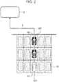
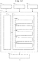
- FIG. 2 is a conceptual diagram illustrating an example of a parking method for the AVP vehicles 10.
- AVP vehicles 10 In the automated valet parking, drivers do not get into and out of vehicles after parking. Therefore, as illustrated in FIG. 2 , many AVP vehicles 10 can be parked at close intervals at front, back, right, and left. That is, a large number of parking slots 4 may be provided without clearances and the AVP vehicles 10 may be parked in those parking slots 4.
- This parking method may also be called "packed parking". The packed parking is preferable from the viewpoint of efficient use of parking spaces.
- exiting vehicle 10X The parked AVP vehicle 10 that is an exit target, that is, the AVP vehicle 10 scheduled to exit the parking lot 1 is hereinafter referred to as "exiting vehicle 10X".
- the exiting vehicle 10X appears in response to an exit request from the user. Alternatively, the exiting vehicle 10X automatically appears before a scheduled exit time specified in advance by the user.
- the exiting vehicle 10X is parked in a parking slot 4X. For the exit of the exiting vehicle 10X, the exiting vehicle 10X needs to move from the parking slot 4X to the boarding/alighting area 2 via the passageway 3.
- the retreating vehicles 10E When one or more retreating vehicles 10E are present, the retreating vehicles 10E first start moving from the parking slots 4E. Then, the exiting vehicle 10X starts moving from the parking slot 4X. The exiting vehicle 10X may start moving before the movement (retreat) of the retreating vehicles 10E is completed. Typically, the exiting vehicle 10X starts moving from the parking slot 4X immediately after the retreating vehicles 10E start moving.
- the traveling route is determined by at least a vehicle position and a traveling direction of the AVP vehicle 10.
- the vehicle position of the AVP vehicle 10 on the traveling route may be given as a function of time. That is, the traveling route may geometrically indicate only a passing position of the AVP vehicle 10, or may indicate a position of the AVP vehicle 10 at a specific timing.
- FIG. 3 is a conceptual diagram illustrating traveling routes of the AVP vehicles 10 in the parking lot 1.
- An “exiting route RX” is a traveling route when the exiting vehicle 10X exits the parking lot 1. That is, the exiting route RX is a traveling route when the exiting vehicle 10X moves from the parking slot 4X to the boarding/alighting area 2.
- a “retreating route RE” is a traveling route of the retreating vehicle 10E when the retreating vehicle 10E is moved in order to move the exiting vehicle 10X. That is, the retreating route RE is a traveling route when the retreating vehicle 10E retreats from the parking slot 4E.
- any other AVP vehicle 10 may be traveling in the passageway 3 in the parking lot 1.
- the other traveling AVP vehicle 10 is hereinafter referred to as "peripheral vehicle 10S".
- the peripheral vehicle 10S is under the entrance process.
- the peripheral vehicle 10S is under the exit process.
- a "peripheral vehicle route RS" is a traveling route of the peripheral vehicle 10S in the parking lot 1.
- the present embodiment proposes a technology for minimizing influence of the movement of the retreating vehicle 10E on the traffic flow in the parking lot 1. Therefore, the retreating route RE of the retreating vehicle 10E is set to minimize interference with the traveling route (exiting route RX or peripheral vehicle route RS) of the other AVP vehicle 10 (exiting vehicle 10X or peripheral vehicle 10S).
- the "interference” means hindrance to the movement of the other AVP vehicle 10. In other words, the "interference” means that the other AVP vehicle 10 is forced to decelerate unnecessarily.
- non-interfering route RN The retreating route RE preferable from the above viewpoint is hereinafter referred to as "non-interfering route RN".
- non-interfering route RN Various examples of the non-interfering route RN will be described below.
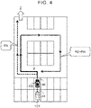
- FIG. 4 is a conceptual diagram illustrating an example of a non-interfering route RN that does not interfere with the exiting route RX.
- the retreating route RE non-interfering route RN
- the exiting route RX partially overlap each other.
- the traveling direction of the retreating vehicle 10E and the traveling direction of the exiting vehicle 10X coincide with each other. That is, the retreating vehicle 10E does not face the exiting vehicle 10X. Therefore, the movement of the retreating vehicle 10E does not hinder the exit of the exiting vehicle 10X.
- the exiting vehicle 10X and the retreating vehicle 10E travel in the same direction. Therefore, it is likely that an orderly traffic flow is made in the parking lot 1. This contributes to improvement in movement efficiency of the AVP vehicles 10 as a whole in the parking lot 1.
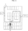
- FIG. 5 is a conceptual diagram illustrating another example of the non-interfering route RN that does not interfere with the exiting route RX.
- the retreating route RE non-interfering route RN
- the exiting route RX do not basically intersect each other on the passageway 3. Therefore, the movement of the retreating vehicle 10E does not hinder the exit of the exiting vehicle 10X.
- the retreating route RE non-interfering route RN
- the exiting route RX slightly overlap each other. Since the exiting vehicle 10X starts moving from the parking slot 4X after the retreating vehicle 10E has started moving from the parking slot 4E, the overlap in the vicinity of the parking slot 4E does not affect the exit of the exiting vehicle 10X.
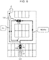
- FIG. 6 is a conceptual diagram illustrating still another example of the non-interfering route RN that does not interfere with the exiting route RX.
- the vehicle position on the traveling route is represented by a function of time, it is possible to grasp a position of the AVP vehicle 10 at a specific timing.
- the traveling direction of the retreating vehicle 10E and the traveling direction of the exiting vehicle 10X are opposite at the same position, no problem arises as long as the timings of the two vehicles passing through the position differ from each other by a predetermined amount or more.
- the retreating vehicle 10E moving along the retreating route RE non-interfering route RN
- the exiting vehicle 10X moving along the exiting route RX be separated by a predetermined distance or more at any time. Also in this case, the movement of the retreating vehicle 10E does not hinder the exit of the exiting vehicle 10X.
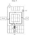
- FIG. 7 is a conceptual diagram illustrating an example of a non-interfering route RN that does not interfere with the peripheral vehicle route RS.
- the retreating route RE non-interfering route RN
- the peripheral vehicle route RS partially overlap each other.
- the traveling direction of the retreating vehicle 10E and the traveling direction of the peripheral vehicle 10S coincide with each other. That is, the retreating vehicle 10E does not face the peripheral vehicle 10S. Therefore, the movement of the retreating vehicle 10E does not hinder the traveling of the peripheral vehicle 10S.
- the peripheral vehicle 10S and the retreating vehicle 10E travel in the same direction. Therefore, it is likely that an orderly traffic flow is made in the parking lot 1. This contributes to improvement in movement efficiency of the AVP vehicles 10 as a whole in the parking lot 1.
- FIG. 8 is a conceptual diagram illustrating another example of the non-interfering route RN that does not interfere with the peripheral vehicle route RS.
- the retreating route RE non-interfering route RN
- the peripheral vehicle route RS do not intersect each other. Therefore, the movement of the retreating vehicle 10E does not hinder the traveling of the peripheral vehicle 10S.
- FIG. 9 is a conceptual diagram illustrating still another example of the non-interfering route RN that does not interfere with the peripheral vehicle route RS.
- the vehicle position on the traveling route is represented by a function of time, it is possible to grasp a position of the AVP vehicle 10 at a specific timing.
- the traveling direction of the retreating vehicle 10E and the traveling direction of the peripheral vehicle 10S are opposite at the same position, no problem arises as long as the timings of the two vehicles passing through the position differ from each other by a predetermined amount or more.
- the retreating vehicle 10E moving along the retreating route RE non-interfering route RN
- the peripheral vehicle 10S moving along the peripheral vehicle route RS be separated by a predetermined distance or more at any time. Also in this case, the movement of the retreating vehicle 10E does not hinder the traveling of the peripheral vehicle 10S.
- FIG. 10 is a conceptual diagram illustrating a "circling route Ra".
- the circling route Ra is a retreating route RE in which the retreating vehicle 10E moves from the original parking slot 4E and then returns to the original parking slot 4E without traveling in backward.
- the circling route Ra can be searched based on the map information of the parking lot 1.
- the non-interfering route RN may be determined to be the circling route Ra. In that case, there is no need to change allocation of the parking slot 4 for the retreating vehicle 10E. This is preferable from the viewpoint of management of the parking slots 4.
- FIG. 11 is a conceptual diagram illustrating a "relocation route Rm".
- the relocation route Rm is a retreating route RE in which the retreating vehicle 10E moves (relocates) from the original parking slot 4E to another available parking slot 4A.
- the relocation route Rm can be searched based on the map information of the parking lot 1 and usage (availability) of each parking slot 4.
- the non-interfering route RN may be determined to be the relocation route Rm. In that case, the moving distance of the retreating vehicle 10E is relatively short. This is preferable from the viewpoint of reduction in energy consumption of the retreating vehicle 10E.
- Priority may be set for either one of the circling route Ra and the relocation route Rm.
- the retreating routes RE of some retreating vehicles 10E may be set to be the circling routes Ra
- the retreating routes RE of the other retreating vehicles 10E may be set to be the relocation routes Rm.
- the non-interfering route RN that does not interfere with at least the exiting route RX is searched.
- the non-interfering route RN is determined as the retreating route RE of the retreating vehicle 10E.
- a "first non-interfering route RN1" and a "second non-interfering route RN2" described below are conceivable.
- the first non-interfering route RN1 is a retreating route RE that interferes with neither the exiting route RX nor the peripheral vehicle route RS. That is, the first non-interfering route RN1 is a combination of any one of the non-interfering routes RN exemplified in FIGS. 4 to 6 and any one of the non-interfering routes RN exemplified in FIGS. 7 to 9 . Any combination is possible.
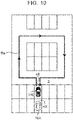
- FIG. 12 is a conceptual diagram illustrating an example of the first non-interfering route RN1.
- the first non-interfering route RN1 illustrated in FIG. 12 is a non-interfering route RN that does not interfere with the exiting route RX illustrated in FIG. 4 , and is also a non-interfering route RN that does not interfere with the peripheral vehicle route RS illustrated in FIG. 7 .
- the first non-interfering route RN1 illustrated in FIG. 12 is also the circling route Ra.
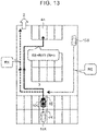
- FIG. 13 is a conceptual diagram illustrating another example of the first non-interfering route RN1.
- the first non-interfering route RN1 illustrated in FIG. 13 corresponds to a part of the first non-interfering route RN1 illustrated in FIG. 12 , and is the relocation route Rm.
- FIG. 14 is a conceptual diagram illustrating still another example of the first non-interfering route RN1.
- the first non-interfering route RN1 illustrated in FIG. 14 is a non-interfering route RN that does not interfere with the exiting route RX illustrated in FIG. 6 , and is also a non-interfering route RN that does not interfere with the peripheral vehicle route RS illustrated in FIG. 7 .
- the first non-interfering route RN1 illustrated in FIG. 14 is also the circling route Ra.
- the first non-interfering route RN1 is determined as the retreating route RE of the retreating vehicle 10E.
- the first non-interfering route RN1 is determined as the retreating route RE of the retreating vehicle 10E.
- the second non-interfering route RN2 is a retreating route RE that may interfere with the peripheral vehicle route RS but does not interfere with at least the exiting route RX. If the first non-interfering route RN1 is not present, the second non-interfering route RN2 is determined as the retreating route RE of the retreating vehicle 10E as the second best measure. Thus, it is possible to minimize at least the influence of the movement of the retreating vehicle 10E on the exit of the exiting vehicle 10X.
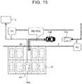
- FIG. 15 is a conceptual diagram illustrating an example of the second non-interfering route RN2.
- the retreating vehicle 10E moves slightly to the right and stops after exiting the parking slot 4E into the passageway 3.
- the exiting vehicle 10X moves to the left toward the boarding/alighting area 2 after exiting the parking slot 4X into the passageway 3.
- the retreating vehicle 10E travels in backward and returns to the original parking slot 4E.
- the peripheral vehicle 10S waits on the passageway 3.
- FIG. 16 is a conceptual diagram illustrating another example of the second non-interfering route RN2.
- the second non-interfering route RN2 illustrated in FIG. 16 is a non-interfering route RN that does not interfere with the exiting route RX illustrated in FIG. 4 , and is the relocation route Rm.
- This second non-interfering route RN2 interferes with the peripheral vehicle route RS of the peripheral vehicle 10S. Therefore, the peripheral vehicle 10S may decelerate or stop on the passageway 3.
- the retreating route RE is determined for each of one or more retreating vehicles 10E.
- the retreating routes RE of some retreating vehicles 10E may be the first non-interfering routes RN1
- the retreating routes RE of the other retreating vehicles 10E may be the second non-interfering routes RN2.
- the retreating route RE of the retreating vehicle 10E is determined.
- the exiting route RX of the exiting vehicle 10X is taken into consideration.
- the non-interfering route RN that does not interfere with at least the exiting route RX is determined as the retreating route RE of the retreating vehicle 10E.
- the first non-interfering route RN1 When there is a first non-interfering route RN1 that interferes with neither the exiting route RX nor the peripheral vehicle route RS, the first non-interfering route RN1 is determined as the retreating route RE of the retreating vehicle 10E. As a result, it is possible to suppress the influence of the movement of the retreating vehicle 10E on the other AVP vehicles 10 and the traffic flow in the parking lot 1. As a result, the decrease in processing efficiency associated with the automated valet parking is suppressed.
- the AVP vehicle 10 and the automated valet parking system 100 according to the present embodiment will be described below in more detail.
- FIG. 17 is a block diagram illustrating a configuration example of the AVP vehicle 10 according to the present embodiment.
- the AVP vehicle 10 includes a vehicle condition sensor 20, a recognition sensor 30, a communication device 40, a travel device 50, and a control device 60.
- the vehicle condition sensor 20 detects conditions of the AVP vehicle 10.
- Examples of the vehicle condition sensor 20 include a vehicle speed sensor (wheel speed sensor), a steering angle sensor, a yaw rate sensor, and a lateral acceleration sensor.
- the recognition sensor 30 recognizes (detects) a situation around the AVP vehicle 10.
- Examples of the recognition sensor 30 include a camera, a laser imaging, detection, and ranging (LIDAR) sensor, and a radar.
- LIDAR laser imaging, detection, and ranging
- the communication device 40 communicates with the outside of the AVP vehicle 10.
- the communication device 40 communicates with the automated valet parking system 100.
- the travel device 50 includes a steering device, a driving device, and a braking device.
- the steering device steers wheels of the AVP vehicle 10.
- the steering device includes an electric power steering (EPS) system.
- the driving device is a driving power source that generates a driving force. Examples of the driving device include an engine, an electric motor, and an in-wheel motor.
- the braking device generates a braking force.
- the control device 60 controls the AVP vehicle 10.
- the control device 60 includes one or more processors 70 (hereinafter referred to simply as “processor 70") and one or more storage devices 80 (hereinafter referred to simply as “storage device 80").
- the processor 70 executes various processes.
- the storage device 80 stores various kinds of information. Examples of the storage device 80 include a volatile memory, a non-volatile memory, a hard disk drive (HDD), and a solid state drive (SSD).
- the control device 60 implements various processes by the processor 70 executing a control program that is a computer program.
- the control program is stored in the storage device 80 or recorded on a computer-readable recording medium.
- the processor 70 executes an information acquisition process for acquiring various kinds of information.
- Various kinds of information include parking lot map information MAP, vehicle condition information VST, surrounding situation information SUR, and the like.
- the acquired information is stored in the storage device 80.
- the parking lot map information MAP is the map information of the parking lot 1. Specifically, the parking lot map information MAP indicates arrangement of the boarding/alighting area 2, the passageway 3, the parking slots 4, the marks 5, and the like in the parking lot 1.
- the parking lot map information MAP is provided by the automated valet parking system 100.
- the processor 70 acquires the parking lot map information MAP from the automated valet parking system 100 via the communication device 40.
- the vehicle condition information VST indicates conditions of the AVP vehicle 10, and indicates detection results from the vehicle condition sensor 20.
- Examples of the conditions of the AVP vehicle 10 include a vehicle speed (wheel speed), a steering angle (wheel steered angle), a yaw rate, and a lateral acceleration.
- the processor 70 acquires the vehicle condition information VST from the vehicle condition sensor 20.
- the surrounding situation information SUR indicates a situation around the AVP vehicle 10, and indicates a recognition result from the recognition sensor 30.
- the surrounding situation information SUR includes information on an image captured by a camera.
- the surrounding situation information SUR includes measurement information indicating a measurement result from the LIDAR sensor or the radar.
- the surrounding situation information SUR includes object information related to objects around the AVP vehicle 10. Examples of the objects around the AVP vehicle 10 include the passageway 3, the parking slots 4, the marks 5, lane marking lines, and other vehicles.
- the object information includes relative positions and relative speeds of the objects to the AVP vehicle 10 (recognition sensor 30).
- the processor 70 can recognize objects around the AVP vehicle 10 and calculate relative positions and relative speeds of the recognized objects. In this way, the processor 70 acquires the surrounding situation information SUR based on the recognition result from the recognition sensor 30. 3-3. Localization Process
- the processor 70 (control device 60) performs a "localization process (self-position estimation process)" for estimating a vehicle position of the AVP vehicle 10 in the parking lot 1.
- the vehicle condition sensor 20 and the recognition sensor 30 are used.
- the processor 70 calculates the amount of movement of the AVP vehicle 10 based on the vehicle condition information VST (vehicle speed, steering angle) obtained by the vehicle condition sensor 20, thereby roughly calculating the vehicle position.
- the processor 70 corrects the vehicle position by comparing an installation position of the mark 5 indicated by the parking lot map information MAP with a recognition position of the mark 5 indicated by the surrounding situation information SUR. As a result, the vehicle position can be estimated (determined) with high accuracy. By repeating the calculation of the movement amount and the correction of the vehicle position, a highly accurate vehicle position can be obtained continuously.
- Localization information LOC indicates a vehicle position estimated by the localization process.
- the processor 70 acquires the localization information LOC by executing the localization process based on the parking lot map information MAP, the vehicle condition information VST, and the surrounding situation information SUR.
- the localization information LOC is stored in the storage device 80.
- the processor 70 communicates with the automated valet parking system 100 via the communication device 40.
- the processor 70 receives an entrance instruction, an exit instruction, and the like from the automated valet parking system 100.
- the processor 70 periodically transmits the vehicle condition information VST, the localization information LOC, and the like to the automated valet parking system 100.
- the processor 70 executes the "vehicle travel control" for controlling the traveling of the AVP vehicle 10 without a driving operation of the driver.
- the vehicle travel control includes steering control, acceleration control, and braking control.
- the processor 70 executes the vehicle travel control by controlling the travel device 50. Specifically, the processor 70 executes the steering control by controlling the steering device.
- the processor 70 also executes the acceleration control by controlling the driving device.
- the processor 70 also executes the braking control by controlling the braking device.
- the processor 70 executes the vehicle travel control in order to cause the AVP vehicle 10 to travel autonomously. Specifically, the processor 70 grasps a map of the parking lot 1 and a vehicle position in the parking lot 1 based on the parking lot map information MAP and the localization information LOC. Then, the processor 70 executes the vehicle travel control such that the AVP vehicle 10 autonomously travels toward a destination.
- the departure place In the case of the entrance process, the departure place is the boarding/alighting area 2 and the destination is an allocated parking slot 4. In the case of the exit process, the departure place is the allocated parking slot 4 (parking slot 4X) and the destination is the boarding/alighting area 2. In the case of the retreating vehicle 10E, the departure place is the parking slot 4E and the destination is the original parking slot 4E (see FIG. 10 ) or another available parking slot 4A (see FIG. 11 ). The positions of the boarding/alighting area 2 and the parking slots 4 are obtained from the parking lot map information MAP.
- Traveling route information RTE indicates a traveling route of the AVP vehicle 10 in the parking lot 1.
- the traveling route is determined by at least a vehicle position and a traveling direction of the AVP vehicle 10.
- the vehicle position of the AVP vehicle 10 on the traveling route may be given as a function of time. That is, the traveling route may geometrically indicate only a passing position of the AVP vehicle 10, or may indicate a position of the AVP vehicle 10 at a specific timing.
- the traveling route information RTE is generated by the automated valet parking system 100 and provided to each AVP vehicle 10.
- the exiting vehicle 10X is provided with traveling route information RTE indicating the exiting route RX.
- the retreating vehicle 10E is provided with traveling route information RTE indicating the retreating route RE.
- the peripheral vehicle 10S is provided with traveling route information RTE indicating the peripheral vehicle route RS (entering route or exiting route).
- the processor 70 of each AVP vehicle 10 acquires the traveling route information RTE from the automated valet parking system 100 via the communication device 40.
- the traveling route information RTE is stored in the storage device 80.
- the traveling route information RTE may be generated by the processor 70 of the AVP vehicle 10.
- the processor 70 communicates with the automated valet parking system 100 via the communication device 40, and acquires information necessary to determine the traveling route. Then, the processor 70 determines the traveling route based on the acquired information and generates the traveling route information RTE.
- the traveling route information RTE is stored in the storage device 80.
- the processor 70 executes the vehicle travel control based on the parking lot map information MAP, the localization information LOC, and the traveling route information RTE so that the AVP vehicle 10 travels along the traveling route.
- the processor 70 may execute the vehicle travel control to avoid a collision with another vehicle by referring to the surrounding situation information SUR.
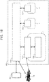
- FIG. 18 is a schematic diagram illustrating a configuration example of the automated valet parking system 100 according to the present embodiment.
- the automated valet parking system 100 includes a vehicle management center 110, a control center 120, and an infrastructure sensor 130.
- the control center 120 is provided for each parking lot 1. Therefore, there are the same number of control centers 120 as the parking lots 1.
- the vehicle management center 110 controls all the control centers 120.
- the infrastructure sensor 130 is installed in the parking lot 1 and recognizes a situation in the parking lot 1.
- the infrastructure sensor 130 includes an infrastructure camera that captures an image of a situation in the parking lot 1.
- FIG. 19 is a block diagram illustrating a configuration example of the control center 120 according to the present embodiment.
- the control center 120 includes an information processing device 121 (controller).
- the information processing device 121 manages the AVP vehicles 10 in the parking lot 1 and also controls the AVP vehicles 10 in the parking lot 1.
- the information processing device 121 includes one or more processors 122 (hereinafter referred to simply as “processor 122") and one or more storage devices 123 (hereinafter referred to simply as “storage device 123").
- the processor 122 executes various processes.
- the storage device 123 stores various kinds of information. Examples of the storage device 123 include a volatile memory, a non-volatile memory, an HDD, and an SSD.
- the information processing device 121 implements various processes by the processor 122 executing a control program that is a computer program.
- the control program is stored in the storage device 123 or recorded on a computer-readable recording medium.
- the information processing device 121 further includes a communication device 124.
- the communication device 124 communicates with the vehicle management center 110, the AVP vehicles 10, and the infrastructure sensor 130 via a communication network.
- the parking lot map information MAP is created in advance and stored in the storage device 123 of the control center 120.
- the processor 122 communicates with the AVP vehicle 10 via the communication device 124, and provides the parking lot map information MAP to the AVP vehicle 10.
- Parking status information PST indicates usage (availability) of each parking slot 4 of the parking lot 1.
- the parking status information PST is stored in the storage device 123.
- the processor 122 manages the usage of each parking slot 4, and updates the parking status information PST every time the entrance process or the exit process is performed.
- Vehicle information VCL is related to each AVP vehicle 10 in the parking lot 1.
- the vehicle information VCL indicates the vehicle position of each AVP vehicle 10 in the parking lot 1.
- the processor 122 communicates with each AVP vehicle 10 via the communication device 124, and acquires the localization information LOC from each AVP vehicle 10.
- the localization information LOC indicates a current vehicle position of each AVP vehicle 10.
- the vehicle information VCL may indicate the parking slot 4 as the vehicle position.
- the vehicle information VCL may include the vehicle condition information VST transmitted from each AVP vehicle 10.
- the vehicle information VCL is stored in the storage device 123.
- the processor 122 allocates an available parking slot 4 to the AVP vehicle 10 scheduled to enter the parking lot 1 based on the parking status information PST.
- the processor 122 determines a traveling route from the boarding/alighting area 2 to the allocated parking slot 4, that is, an entering route based on the parking lot map information MAP.
- the traveling route information RTE indicates the determined entering route.
- the processor 122 communicates with the AVP vehicle 10 via the communication device 124, and transmits an entrance instruction to the AVP vehicle 10.
- the entrance instruction includes the parking lot map information MAP and the traveling route information RTE indicating the entering route, and is an instruction to move along the entering route.
- the processor 122 changes the status of the allocated parking slot 4 to "in use" and updates the parking status information PST.
- the processor 122 determines a traveling route from the parking slot 4X to the boarding/alighting area 2, that is, the exiting route RX based on the parking lot map information MAP.
- the traveling route information RTE indicates the determined exiting route RX.
- the processor 122 communicates with the exiting vehicle 10X via the communication device 124, and transmits an exit instruction to the exiting vehicle 10X.
- the exit instruction includes the parking lot map information MAP and the traveling route information RTE indicating the exiting route RX, and is an instruction to move along the exiting route RX.
- the processor 122 changes the status of the parking slot 4X to "available" and updates the parking status information PST.
- the peripheral vehicle 10S is an AVP vehicle 10 traveling in the parking lot 1, that is, an AVP vehicle 10 entering or exiting the parking lot 1.
- the peripheral vehicle route RS is the entering route or the exiting route RX.
- the traveling route information RTE stored in the storage device 123 of the control center 120 is a set of pieces of traveling route information RTE related to the AVP vehicles 10 in the parking lot 1. That is, the traveling route information RTE indicates the exiting route RX of the exiting vehicle 10X, the peripheral vehicle route RS of the peripheral vehicle 10S, and the retreating route RE of the retreating vehicle 10E.
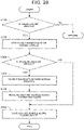
- FIG. 20 is a flowchart illustrating the vehicle control process during exit according to the present embodiment.
- Step S100 the processor 122 of the control center 120 determines whether the exiting vehicle 10X is present. For example, the exiting vehicle 10X appears in response to an exit request from a user. The exit request is transmitted from the user's terminal device 200 to the vehicle management center 110. The exit request is further transmitted from the vehicle management center 110 to the control center 120. As another example, the exiting vehicle 10X automatically appears before a scheduled exit time specified in advance by the user. When the exiting vehicle 10X is not present (Step S100; NO), the process in this cycle is terminated. When the exiting vehicle 10X is present (Step S100; YES), the process proceeds to Step S200.
- Step S200 the processor 122 of the control center 120 determines the exiting route RX of the exiting vehicle 10X.
- the exiting route RX is a traveling route from the parking slot 4X to the boarding/alighting area 2.
- the processor 122 can determine the exiting route RX based on the parking lot map information MAP.
- the peripheral vehicle route RS of the peripheral vehicle 10S traveling in the parking lot 1 has already been determined.
- the processor 122 may determine the exiting route RX by referring to the traveling route information RTE so that the exiting route RX does not interfere with the peripheral vehicle route RS.
- the traveling route information RTE indicating the determined exiting route RX is stored in the storage device 123.
- Step S300 the processor 122 of the control center 120 determines whether the retreating vehicle 10E is present.
- the retreating vehicle 10E is an AVP vehicle 10 parked in the parking slot 4E that is in front of the exiting vehicle 10X to hinder the movement of the exiting vehicle 10X.
- the arrangement of the parking slots 4 is obtained from the parking lot map information MAP.
- the vehicle position of each AVP vehicle 10 in the parking lot 1 is obtained from the vehicle information VCL.
- the processor 122 acquires the parking lot map information MAP and the vehicle information VCL from the storage device 123.
- the processor 122 determines whether the retreating vehicle 10E is present based on the parking lot map information MAP and the vehicle information VCL.
- Step S400 the processor 122 of the control center 120 executes the "retreating route determination process" for determining the retreating route RE of the retreating vehicle 10E.
- the processor 122 searches for a non-interfering route RN that does not interfere with at least the exiting route RX of the exiting vehicle 10X. Then, the processor 122 determines the non-interfering route RN as the retreating route RE. Various examples of this retreating route determination process will be described later.
- the process proceeds to Step S500.
- Step S500 the processor 122 of the control center 120 moves the retreating vehicle 10E along the retreating route RE.
- the processor 122 communicates with the retreating vehicle 10E via the communication device 124, and transmits a retreat instruction to the retreating vehicle 10E.
- the retreat instruction includes the parking lot map information MAP and the traveling route information RTE indicating the retreating route RE, and is an instruction to move along the retreating route RE.
- the processor 70 of the retreating vehicle 10E receives the retreat instruction from the control center 120 via the communication device 40. In response to the retreat instruction, the processor 70 of the retreating vehicle 10E executes the vehicle travel control.
- the processor 70 executes the vehicle travel control based on the parking lot map information MAP, the localization information LOC, and the traveling route information RTE so that the retreating vehicle 10E travels along the retreating route RE.
- the process proceeds to Step S600.
- Step S600 the processor 122 of the control center 120 moves the exiting vehicle 10X along the exiting route RX.
- the processor 122 communicates with the exiting vehicle 10X via the communication device 124, and transmits an exit instruction to the exiting vehicle 10X.
- the exit instruction includes the parking lot map information MAP and the traveling route information RTE indicating the exiting route RX, and is an instruction to move along the exiting route RX.
- the processor 70 of the exiting vehicle 10X receives the exit instruction from the control center 120 via the communication device 40.
- the processor 70 of the exiting vehicle 10X executes the vehicle travel control. Specifically, the processor 70 executes the vehicle travel control based on the parking lot map information MAP, the localization information LOC, and the traveling route information RTE so that the exiting vehicle 10X travels along the exiting route RX.
- FIG. 21 is a flowchart illustrating the retreating route determination process (Step S400).
- Step S410 the processor 122 of the control center 120 searches for the first non-interfering route RN1. In other words, the processor 122 determines whether the first non-interfering route RN1 is present.
- the first non-interfering route RN1 is a retreating route RE that interferes with neither the exiting route RX of the exiting vehicle 10X nor the peripheral vehicle route RS of the peripheral vehicle 10S (see FIGS. 12 to 14 ).
- the processor 122 acquires the parking lot map information MAP, the traveling route information RTE, and the vehicle information VCL from the storage device 123.
- the traveling route information RTE indicates the exiting route RX of the exiting vehicle 10X and the peripheral vehicle route RS of the peripheral vehicle 10S.
- the current position of the peripheral vehicle 10S is obtained from the vehicle information VCL.
- the processor 122 searches for the first non-interfering route RN1 based on the parking lot map information MAP, the traveling route information RTE, and the vehicle information VCL.
- the parking status information PST is also used.
- Step S410 When the first non-interfering route RN1 is found, that is, when the first non-interfering route RN1 is present (Step S410; YES), the process proceeds to Step S420.
- Step S420 the processor 122 determines the first non-interfering route RN1 as the retreating route RE of the retreating vehicle 10E.
- Step S410 the process proceeds to Step S430.
- the processor 122 searches for the second non-interfering route RN2 that does not interfere with the exiting route RX based on the parking lot map information MAP and the exiting route RX (see FIGS. 15 and 16 ).
- the parking status information PST is also used.
- the processor 122 determines the second non-interfering route RN2 as the retreating route RE of the retreating vehicle 10E.
- Step S400 is performed for each of one or more retreating vehicles 10E.
- the retreating routes RE of some retreating vehicles 10E may be the first non-interfering routes RN1
- the retreating routes RE of the other retreating vehicles 10E may be the second non-interfering routes RN2.
- Step S410 Various examples of Step S410 will be described below.
- FIG. 22 is a flowchart illustrating a first example of Step S410.
- the two types of retreating route RE that are the circling route Ra (see FIG. 10 ) and the relocation route Rm ( FIG. 11 ) are conceivable.
- a search is made for the circling route Ra with priority.
- Step S411 the processor 122 first searches for the circling route Ra as the first non-interfering route RN1.
- the circling route Ra is a first non-interfering route RN1 in which the retreating vehicle 10E moves from the original parking slot 4E and then returns to the original parking slot 4E without traveling in backward (see FIG. 10 ).
- the processor 122 searches for the circling route Ra serving as the first non-interfering route RN1 based on the parking lot map information MAP, the traveling route information RTE, and the vehicle information VCL.
- Step S411; YES the process proceeds to Step S417. In other cases (Step S411; NO), the process proceeds to Step S414.
- Step S414 the processor 122 searches for the relocation route Rm as the first non-interfering route RN1.
- the relocation route Rm is a first non-interfering route RN1 in which the retreating vehicle 10E moves (relocates) from the original parking slot 4E to another available parking slot 4A (see FIG. 11 ).
- the available parking slot 4A is obtained from the parking status information PST.
- the processor 122 searches for the relocation route Rm serving as the first non-interfering route RN1 based on the parking lot map information MAP, the traveling route information RTE, the vehicle information VCL, and the parking status information PST.
- Step S417 the processor 122 sets the circling route Ra as the first non-interfering route RN1.
- Step S418, the processor 122 sets the relocation route Rm as the first non-interfering route RN1.
- the processor 122 changes the parking slot 4 allocated to the retreating vehicle 10E to the parking slot 4A, and updates the parking status information PST.
- Step S410 is performed for each of one or more retreating vehicles 10E.
- the retreating routes RE of some retreating vehicles 10E may be set as the circling routes Ra, and the retreating routes RE of the other retreating vehicles 10E may be set as the relocation routes Rm.
- a search is made for the circling route Ra with priority.
- the circling route Ra is adopted as the retreating route RE, there is no need to change the allocation of the parking slot 4 to the retreating vehicle 10E and to update the parking status information PST. This is preferable from the viewpoint of management of the parking slots 4.
- FIG. 23 is a flowchart illustrating a second example of Step S410.
- the second example is a modification of the first example. Description overlapping that of the first example will be omitted as appropriate.
- Step S412 the processor 122 determines whether the length of the circling route Ra is less than a predetermined threshold.
- the length of the circling route Ra can be calculated based on the parking lot map information MAP.
- Step S412; YES the process proceeds to Step S417.
- Step S412; NO the process proceeds to Step S414.
- selection of an excessively long circling route Ra is avoided. This eliminates the need to move the retreating vehicle 10E over a long distance in the parking lot 1. This is preferable from the viewpoint of reduction in energy consumption of the retreating vehicle 10E.
- FIG. 24 is a flowchart illustrating a third example of Step S410.
- the third example is a modification of the first example. Description overlapping that of the first example will be omitted as appropriate.
- Step S413 the processor 122 calculates an expected return time when the retreating vehicle 10E is expected to travel along the circling route Ra and return to the original parking slot 4E.
- the vehicle speed in the parking lot 1 is set to a constant speed.
- the length of the circling route Ra can be calculated based on the parking lot map information MAP. Therefore, the processor 122 can calculate the expected return time based on the constant speed and the length of the circling route Ra.
- the processor 122 determines whether the expected return time is earlier than a scheduled exit start time of the retreating vehicle 10E. In other words, the processor 122 determines whether the expected return time has a margin before the exit of the retreating vehicle 10E.
- the scheduled exit start time of the retreating vehicle 10E is managed by the vehicle management center 110 or the control center 120.
- the processor 122 acquires information on the scheduled exit start time of the retreating vehicle 10E from the vehicle management center 110 via the communication device 124.
- the process proceeds to Step S417.
- the process proceeds to Step S414.
- a delay in the exit of the retreating vehicle 10E due to the circling route Ra is suppressed.
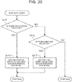
- FIG. 25 is a flowchart illustrating a fourth example of Step S410.
- a search is made for the relocation route Rm with priority.
- Step S415 the processor 122 first searches for the relocation route Rm as the first non-interfering route RN1. Step S415 is performed similarly to Step S414. When the relocation route Rm is found (Step S415; YES), the process proceeds to Step S418. In other cases (Step S415; NO), the process proceeds to Step S416.
- Step S416 the processor 122 searches for the circling route Ra as the first non-interfering route RN1.
- Step S416 is performed similarly to Step S411.
- the process proceeds to Step S417.
- Step S416; NO the process proceeds to Step S430.
- a search is made for the relocation route Rm with priority.
- the relocation route Rm is adopted as the retreating route RE, the moving distance of the retreating vehicle 10E is relatively short. This is preferable from the viewpoint of reduction in energy consumption of the retreating vehicle 10E.
- the traveling route in the parking lot 1 may be determined by the AVP vehicle 10.
- the exiting route RX may be determined by the exiting vehicle 10X (Step S200).
- the retreating route RE may be determined by the retreating vehicle 10E (Step S400).
- the processor 70 of the AVP vehicle 10 communicates with the control center 120 via the communication device 40, and acquires information necessary to determine the traveling route. Then, the processor 70 determines the traveling route based on the acquired information and generates the traveling route information RTE.
- the control device 60 of the AVP vehicle 10 (see FIG. 17 ) and the information processing device 121 of the control center 120 (see FIG. 19 ) constitute a "vehicle control system" that controls the AVP vehicle 10.
- the vehicle control system includes one or more processors (70, 122) and one or more storage devices (80, 123).
- the one or more processors perform the processes illustrated in FIGS. 20 to 25 .
- the one or more storage devices store various kinds of information necessary for the processes to be performed by the one or more processors.
Landscapes
- Engineering & Computer Science (AREA)
- Physics & Mathematics (AREA)
- Transportation (AREA)
- Mechanical Engineering (AREA)
- Automation & Control Theory (AREA)
- General Physics & Mathematics (AREA)
- Human Computer Interaction (AREA)
- Chemical & Material Sciences (AREA)
- Mathematical Physics (AREA)
- Remote Sensing (AREA)
- Analytical Chemistry (AREA)
- Radar, Positioning & Navigation (AREA)
- Combustion & Propulsion (AREA)
- Traffic Control Systems (AREA)
- Navigation (AREA)
- Control Of Driving Devices And Active Controlling Of Vehicle (AREA)
- Train Traffic Observation, Control, And Security (AREA)
Abstract
Description
- The present disclosure relates to a vehicle control method, a vehicle control system, and an information processing device for controlling a vehicle adapted to automated valet parking (AVP) in a parking lot.
-
Japanese Unexamined Patent Application Publication No. 2020-149537 JP 2020-149537 A -
Japanese Unexamined Patent Application Publication No. 2018-188027 JP 2018-188027 A -
Japanese Unexamined Patent Application Publication No. 2011-235816 JP 2011-235816 A - Automated valet parking in a parking lot is known. A vehicle adapted to the automated valet parking travels autonomously at least in the parking lot. In the automated valet parking, drivers do not get into and out of vehicles after parking. Therefore, many vehicles can be parked at close intervals at front, back, right, and left ("packed parking"). Such a parking method is preferable from the viewpoint of efficient use of parking spaces.
- However, any other vehicle may be parked in a parking slot that is in front of an exiting vehicle scheduled to exit the parking lot. That is, a parked vehicle may hinder movement of the exiting vehicle. In that case, it is necessary to first move (retreat) the parked vehicle that is hindering the movement of the exiting vehicle before starting the movement of the exiting vehicle. However, the movement (retreat) of the parked vehicle may disturb or stagnate a traffic flow in the parking lot. This causes a decrease in processing efficiency associated with the automated valet parking.
- The present disclosure provides a vehicle control method, a vehicle control system, and an information processing device capable of suppressing influence of vehicle movement along with exit of an exiting vehicle on a traffic flow in a parking lot in relation to automated valet parking in the parking lot.
- A first aspect of the present disclosure relates to a vehicle control method for controlling vehicles adapted to automated valet parking in a parking lot. The vehicle control method includes acquiring map information of the parking lot and vehicle information indicating positions of the vehicles in the parking lot, determining whether a retreating vehicle is present based on the map information and the vehicle information, determining a retreating route through a retreating route determination process, and moving the retreating vehicle along the retreating route. The retreating vehicle is a vehicle that needs to move from a parking slot where the retreating vehicle is parked to move an exiting vehicle scheduled to exit the parking lot. The retreating route is a traveling route of the retreating vehicle when the retreating vehicle is moved to move the exiting vehicle. The retreating route determination process includes acquiring traveling route information indicating an exiting route that is a traveling route of the exiting vehicle, searching, through a non-interfering route search process, for a non-interfering route that does not interfere with the exiting route based on the map information, the vehicle information, and the traveling route information, and determining the non-interfering route as the retreating route.
- In the vehicle control method according to the first aspect of the present disclosure, non-interference between the non-interfering route and the exiting route may include at least one of the following conditions: a traveling direction of the retreating vehicle and a traveling direction of the exiting vehicle coincide with each other at a position where the non-interfering route and the exiting route overlap each other, the non-interfering route and the exiting route do not intersect each other on a passageway except a vicinity of the parking slot where the retreating vehicle is parked, and the retreating vehicle moving along the non-interfering route and the exiting vehicle moving along the exiting route are separated by a predetermined distance or more at any time.
- In the vehicle control method according to the first aspect of the present disclosure, the traveling route information may further indicate a peripheral vehicle route that is a traveling route of a peripheral vehicle traveling in the parking lot. The retreating route determination process may include searching for a first non-interfering route based on the map information, the vehicle information, and the traveling route information and determining the first non-interfering route as the retreating route when the first non-interfering route is found. The first non-interfering route may be the non-interfering route that interferes with neither the exiting route nor the peripheral vehicle route.
- In the vehicle control method according to the first aspect of the present disclosure, non-interference between the non-interfering route and the peripheral vehicle route may include at least one of the following conditions: a traveling direction of the retreating vehicle and a traveling direction of the peripheral vehicle coincide with each other at a position where the non-interfering route and the peripheral vehicle route overlap each other, the non-interfering route and the peripheral vehicle route do not intersect each other, and the retreating vehicle moving along the non-interfering route and the peripheral vehicle moving along the peripheral vehicle route are separated by a predetermined distance or more at any time.
- In the vehicle control method according to the first aspect of the present disclosure, the retreating route determination process may include determining a second non-interfering route as the retreating route when the first non-interfering route is not found. The second non-interfering may be the non-interfering route that does not interfere with the exiting route.
- In the vehicle control method according to the first aspect of the present disclosure, the non-interfering route may be a circling route in which the retreating vehicle moves from an original parking slot and then returns to the original parking slot.
- In the vehicle control method according to the first aspect of the present disclosure, the non-interfering route may be a relocation route in which the retreating vehicle moves from an original parking slot to another available parking slot.
- In the vehicle control method according to the first aspect of the present disclosure, the non-interfering route search process may include searching for a circling route, setting the circling route as the non-interfering route when the circling route is found, searching, when the circling route is not found, for a relocation route based on parking status information indicating usage of each parking slot in the parking lot, and setting the relocation route as the non-interfering route when the relocation route is found. The circling route may be the non-interfering route in which the retreating vehicle moves from an original parking slot and then returns to the original parking slot. The relocation route may be the non-interfering route in which the retreating vehicle moves from the original parking slot to another available parking slot.
- In the vehicle control method according to the first aspect of the present disclosure, the non-interfering route search process may include searching for a circling route, determining, when the circling route is found, whether a length of the circling route is less than a threshold, setting the circling route as the non-interfering route when the length of the circling route is less than the threshold, searching, when the circling route is not found or when the length of the circling route is equal to or more than the threshold, for a relocation route based on parking status information indicating usage of each parking slot in the parking lot, and setting the relocation route as the non-interfering route when the relocation route is found. The circling route may be the non-interfering route in which the retreating vehicle moves from an original parking slot and then returns to the original parking slot. The relocation route may be the non-interfering route in which the retreating vehicle moves from the original parking slot to another available parking slot.
- In the vehicle control method according to the first aspect of the present disclosure, the non-interfering route search process may include searching for a circling route, determining, when the circling route is found, whether an expected return time is earlier than a scheduled exit start time of the retreating vehicle, setting the circling route as the non-interfering route when the expected return time is earlier than the scheduled exit start time, searching, when the circling route is not found or when the expected return time is later than the scheduled exit start time, for a relocation route based on parking status information indicating usage of each parking slot in the parking lot, and setting the relocation route as the non-interfering route when the relocation route is found. The circling route may be the non-interfering route in which the retreating vehicle moves from the original parking slot and then returns to the original parking slot. The expected return time may be a time when the retreating vehicle is expected to return to an original parking slot. The relocation route may be the non-interfering route in which the retreating vehicle moves from the original parking slot to another available parking slot.
- In the vehicle control method according to the first aspect of the present disclosure, the non-interfering route search process may include searching for a relocation route based on parking status information indicating usage of each parking slot in the parking lot, setting the relocation route as the non-interfering route when the relocation route is found, searching for a circling route when the relocation route is not found, and setting the circling route as the non-interfering route when the circling route is found. The relocation route may be the non-interfering route in which the retreating vehicle moves from an original parking slot to another available parking slot. The circling route may be the non-interfering route in which the retreating vehicle moves from the original parking slot and then returns to the original parking slot.
- The vehicle control method according to the first aspect of the present disclosure may include moving the exiting vehicle along the exiting route after starting movement of the retreating vehicle.
- A second aspect of the present disclosure relates to a vehicle control system configured to control vehicles adapted to automated valet parking in a parking lot. The vehicle control system includes one or more storage devices configured to store map information of the parking lot and vehicle information indicating positions of the vehicles in the parking lot, and one or more processors. The processors are configured to determine whether a retreating vehicle is present based on the map information and the vehicle information, determine a retreating route through a retreating route determination process, and move the retreating vehicle along the retreating route. The retreating vehicle is a vehicle that needs to move from a parking slot where the retreating vehicle is parked to move an exiting vehicle scheduled to exit the parking lot. The retreating route is a traveling route of the retreating vehicle when the retreating vehicle is moved to move the exiting vehicle. The retreating route determination process includes acquiring traveling route information indicating an exiting route that is a traveling route of the exiting vehicle, searching for a non-interfering route that does not interfere with the exiting route based on the map information, the vehicle information, and the traveling route information, and determining the non-interfering route as the retreating route.
- A third aspect of the present disclosure relates to an information processing device configured to control vehicles adapted to automated valet parking in a parking lot. The information processing device includes one or more storage devices configured to store map information of the parking lot and vehicle information indicating positions of the vehicles in the parking lot, and one or more processors. The processors are configured to determine whether a retreating vehicle is present based on the map information and the vehicle information, determine a retreating route through a retreating route determination process, and move the retreating vehicle along the retreating route. The retreating vehicle is a vehicle that needs to move from a parking slot where the retreating vehicle is parked to move an exiting vehicle scheduled to exit the parking lot. The retreating route is a traveling route of the retreating vehicle when the retreating vehicle is moved to move the exiting vehicle. The retreating route determination process includes acquiring traveling route information indicating an exiting route that is a traveling route of the exiting vehicle, searching for a non-interfering route that does not interfere with the exiting route based on the map information, the vehicle information, and the traveling route information, and determining the non-interfering route as the retreating route.
- According to the present disclosure, when any retreating vehicle needs to move for the exit of the exiting vehicle, the retreating route of the retreating vehicle is determined. In the determination of the retreating route, at least the exiting route of the exiting vehicle is taken into consideration. The non-interfering route that does not interfere with at least the exiting route is determined as the retreating route of the retreating vehicle. As a result, it is possible to suppress influence of the movement of the retreating vehicle on a traffic flow in the parking lot. As a result, the decrease in processing efficiency associated with the automated valet parking is suppressed.
- Features, advantages, and technical and industrial significance of exemplary embodiments of the invention will be described below with reference to the accompanying drawings, in which like signs denote like elements, and wherein:
-
FIG. 1 is a conceptual diagram illustrating an overview of an automated valet parking system according to an embodiment of the present disclosure; -
FIG. 2 is a conceptual diagram illustrating an example of a parking method for AVP vehicles according to the embodiment of the present disclosure; -
FIG. 3 is a conceptual diagram illustrating the AVP vehicles and traveling routes according to the embodiment of the present disclosure; -
FIG. 4 is a conceptual diagram illustrating an example of a non-interfering route that does not interfere with an exiting route according to the embodiment of the present disclosure; -
FIG. 5 is a conceptual diagram illustrating another example of the non-interfering route that does not interfere with the exiting route according to the embodiment of the present disclosure; -
FIG. 6 is a conceptual diagram illustrating still another example of the non-interfering route that does not interfere with the exiting route according to the embodiment of the present disclosure; -
FIG. 7 is a conceptual diagram illustrating an example of a non-interfering route that does not interfere with a peripheral vehicle route according to the embodiment of the present disclosure; -
FIG. 8 is a conceptual diagram illustrating another example of the non-interfering route that does not interfere with the peripheral vehicle route according to the embodiment of the present disclosure; -
FIG. 9 is a conceptual diagram illustrating still another example of the non-interfering route that does not interfere with the peripheral vehicle route according to the embodiment of the present disclosure; -
FIG. 10 is a conceptual diagram illustrating an example of a circling route according to the embodiment of the present disclosure; -
FIG. 11 is a conceptual diagram illustrating an example of a relocation route according to the embodiment of the present disclosure; -
FIG. 12 is a conceptual diagram illustrating an example of a first non-interfering route according to the embodiment of the present disclosure; -
FIG. 13 is a conceptual diagram illustrating another example of the first non-interfering route according to the embodiment of the present disclosure; -
FIG. 14 is a conceptual diagram illustrating still another example of the first non-interfering route according to the embodiment of the present disclosure; -
FIG. 15 is a conceptual diagram illustrating an example of a second non-interfering route according to the embodiment of the present disclosure; -
FIG. 16 is a conceptual diagram illustrating another example of the second non-interfering route according to the embodiment of the present disclosure; -
FIG. 17 is a block diagram illustrating a configuration example of the AVP vehicle according to the embodiment of the present disclosure; -
FIG. 18 is a schematic diagram illustrating a configuration example of the automated valet parking system according to the embodiment of the present disclosure; -
FIG. 19 is a block diagram illustrating a configuration example of a control center according to the embodiment of the present disclosure; -
FIG. 20 is a flowchart illustrating a vehicle control process during exit according to the embodiment of the present disclosure; -
FIG. 21 is a flowchart illustrating a retreating route determination process (Step S400) according to the embodiment of the present disclosure; -
FIG. 22 is a flowchart illustrating a first example of Step S410 according to the embodiment of the present disclosure; -
FIG. 23 is a flowchart illustrating a second example of Step S410 according to the embodiment of the present disclosure; -
FIG. 24 is a flowchart illustrating a third example of Step S410 according to the embodiment of the present disclosure; and -
FIG. 25 is a flowchart illustrating a fourth example of Step S410 according to the embodiment of the present disclosure. - An embodiment of the present disclosure will be described with reference to the accompanying drawings.
-
FIG. 1 is a conceptual diagram illustrating an overview of an automatedvalet parking system 100 according to the present embodiment. The automatedvalet parking system 100 manages automated valet parking (AVP) in aparking lot 1. - A vehicle adapted to the automated valet parking will be hereinafter referred to as "
AVP vehicle 10". TheAVP vehicle 10 can communicate with the automatedvalet parking system 100. TheAVP vehicle 10 can also travel without driving operation by a driver at least in theparking lot 1. TheAVP vehicle 10 may be an autonomous driving vehicle. When an autonomous traveling robot tows a vehicle that does not have an autonomous driving function to realize the automated valet parking, the combination of the vehicle and the autonomous traveling robot corresponds to the "AVP vehicle 10". In this case, control on theAVP vehicle 10 means control on the autonomous traveling robot. - The
parking lot 1 is used by at least theAVP vehicle 10. Theparking lot 1 may be used by a general vehicle other than theAVP vehicle 10. - The
parking lot 1 includes a boarding/alighting area 2, apassageway 3, and a plurality of parking slots (parking sections) 4. In the boarding/alighting area 2, theAVP vehicle 10 entering theparking lot 1 or theAVP vehicle 10 exiting theparking lot 1 stops. In the boarding/alighting area 2, an occupant gets out of theAVP vehicle 10 and also gets into theAVP vehicle 10. Thepassageway 3 is an area in which vehicles such as theAVP vehicle 10 and a general vehicle travel. The parking slot 4 is a space for parking a vehicle such as theAVP vehicle 10 or a general vehicle. For example, the parking slots 4 are separated by demarcation lines. - In addition, a plurality of marks 5 is provided in the
parking lot 1. The marks 5 are used to guide theAVP vehicle 10 in theparking lot 1. Examples of the marks 5 include markers and pillars. - An example of a flow in which a user X uses the automated valet parking service will be described below. It is assumed that member information of the user X is preregistered in the automated
valet parking system 100. - First, the user X makes a reservation for automated valet parking. For example, the user X operates a
terminal device 200 to input identification (ID) information of the user X, a desiredparking lot 1, a desired date of use, a desired period of use (desired entrance time and desired exit time), and the like. Theterminal device 200 transmits reservation information including the input information to the automatedvalet parking system 100. The automatedvalet parking system 100 performs a reservation process based on the reservation information. The automatedvalet parking system 100 transmits a reservation completion notification to theterminal device 200. The automatedvalet parking system 100 also transmits authentication information associated with the reservation information to theterminal device 200. Theterminal device 200 receives the authentication information and holds the received authentication information. - The entrance (check-in) of the
AVP vehicle 10 into theparking lot 1 is as follows. - The
AVP vehicle 10 carrying the user X arrives and stops at the boarding/alighting area 2 of theparking lot 1. In the boarding/alighting area 2, the user X (and other occupants, if any) gets out of theAVP vehicle 10. Then, the user X requests entrance of theAVP vehicle 10 by using the authentication information held in theterminal device 200. In response to the entrance request, the automatedvalet parking system 100 authenticates the user X. When the authentication is completed, operation authority of theAVP vehicle 10 is transferred from the user X to the automatedvalet parking system 100. The automatedvalet parking system 100 performs an entrance process for theAVP vehicle 10. - In the entrance process, the automated
valet parking system 100 communicates with theAVP vehicle 10 and activates the AVP vehicle 10 (ignition ON). - The automated
valet parking system 100 allocates an available parking slot 4 to theAVP vehicle 10 with reference to usage of theparking lot 1. Then, the automatedvalet parking system 100 communicates with theAVP vehicle 10 and transmits an entrance instruction to theAVP vehicle 10. The entrance instruction includes information on the allocated parking slot 4 and map information of theparking lot 1. The automatedvalet parking system 100 may specify a traveling route from the boarding/alighting area 2 to the allocated parking slot 4. In that case, the entrance instruction includes information on the specified traveling route. - In response to the entrance instruction, the
AVP vehicle 10 starts vehicle travel control. Specifically, theAVP vehicle 10 autonomously travels in thepassageway 3 from the boarding/alighting area 2 to the allocated parking slot 4, and is autonomously parked in the allocated parking slot 4. At this time, theAVP vehicle 10 may travel along the traveling route specified by the automatedvalet parking system 100. The automatedvalet parking system 100 may communicate with theAVP vehicle 10 and remotely control the autonomous traveling of theAVP vehicle 10. - When parking is completed, the
AVP vehicle 10 notifies the automatedvalet parking system 100 about the completion of parking. Alternatively, the automatedvalet parking system 100 may detect the completion of parking of theAVP vehicle 10 by using infrastructure sensors installed in theparking lot 1. After the parking is completed, the automatedvalet parking system 100 communicates with theAVP vehicle 10 and stops the operation of the AVP vehicle 10 (ignition OFF). The automatedvalet parking system 100 holds the information on the parking slot 4 of theAVP vehicle 10 in association with the user X. - The exit (check-out) of the
AVP vehicle 10 from theparking lot 1 is as follows. - The user X requests exit of the
AVP vehicle 10 by using theterminal device 200. The exit request includes the authentication information, information on the boarding/alighting area 2 specified by the user X, and the like. In response to the exit request, the automatedvalet parking system 100 authenticates the user X and performs an exit process for theAVP vehicle 10. - In the exit process, the automated
valet parking system 100 communicates with theAVP vehicle 10 and activates the AVP vehicle 10 (ignition ON). - The automated
valet parking system 100 communicates with theAVP vehicle 10 and transmits an exit instruction to theAVP vehicle 10. The exit instruction includes the information on the boarding/alighting area 2 specified by the user X and the map information of theparking lot 1. The automatedvalet parking system 100 may specify a traveling route from the parking slot 4 to the boarding/alighting area 2. In that case, the exit instruction includes information on the specified traveling route. - In response to the exit instruction, the
AVP vehicle 10 starts the vehicle travel control. Specifically, theAVP vehicle 10 autonomously travels in thepassageway 3 from the parking slot 4 to the specified boarding/alighting area 2. At this time, theAVP vehicle 10 may travel along the traveling route specified by the automatedvalet parking system 100. The automatedvalet parking system 100 may communicate with theAVP vehicle 10 and remotely control the autonomous traveling of theAVP vehicle 10. - The
AVP vehicle 10 arrives and stops at the boarding/alighting area 2 specified by the user X. The operation authority of theAVP vehicle 10 is transferred from the automatedvalet parking system 100 to the user X. The user X (and other occupants, if any) gets into theAVP vehicle 10. TheAVP vehicle 10 starts traveling toward the next destination. -
FIG. 2 is a conceptual diagram illustrating an example of a parking method for theAVP vehicles 10. In the automated valet parking, drivers do not get into and out of vehicles after parking. Therefore, as illustrated inFIG. 2 ,many AVP vehicles 10 can be parked at close intervals at front, back, right, and left. That is, a large number of parking slots 4 may be provided without clearances and theAVP vehicles 10 may be parked in those parking slots 4. This parking method may also be called "packed parking". The packed parking is preferable from the viewpoint of efficient use of parking spaces. - It is assumed that a certain parked
AVP vehicle 10 is caused to exit theparking lot 1. The parkedAVP vehicle 10 that is an exit target, that is, theAVP vehicle 10 scheduled to exit theparking lot 1 is hereinafter referred to as "exitingvehicle 10X". The exitingvehicle 10X appears in response to an exit request from the user. Alternatively, the exitingvehicle 10X automatically appears before a scheduled exit time specified in advance by the user. The exitingvehicle 10X is parked in aparking slot 4X. For the exit of the exitingvehicle 10X, the exitingvehicle 10X needs to move from theparking slot 4X to the boarding/alighting area 2 via thepassageway 3. - In the situation illustrated in
FIG. 2 ,other parking slots 4E are present between theparking slot 4X and thepassageway 3, andother AVP vehicles 10E are parked in theparking slots 4E. That is, theother AVP vehicles 10E are parked to obstruct a space that is in front of the exitingvehicle 10X. TheAVP vehicles 10E hinder (block) the exit movement of the exitingvehicle 10X. Before moving the exitingvehicle 10X, it is necessary to temporarily move (retreat) theAVP vehicles 10E from theparking slots 4E. In that sense, theAVP vehicle 10E that needs to move (retreat) in order to move the exitingvehicle 10X is hereinafter referred to as "retreatingvehicle 10E". - When one or more retreating
vehicles 10E are present, the retreatingvehicles 10E first start moving from theparking slots 4E. Then, the exitingvehicle 10X starts moving from theparking slot 4X. The exitingvehicle 10X may start moving before the movement (retreat) of the retreatingvehicles 10E is completed. Typically, the exitingvehicle 10X starts moving from theparking slot 4X immediately after the retreatingvehicles 10E start moving. - Next, consideration is made about traveling routes of the
AVP vehicles 10 in theparking lot 1. The traveling route is determined by at least a vehicle position and a traveling direction of theAVP vehicle 10. The vehicle position of theAVP vehicle 10 on the traveling route may be given as a function of time. That is, the traveling route may geometrically indicate only a passing position of theAVP vehicle 10, or may indicate a position of theAVP vehicle 10 at a specific timing. -
FIG. 3 is a conceptual diagram illustrating traveling routes of theAVP vehicles 10 in theparking lot 1. An "exiting route RX" is a traveling route when the exitingvehicle 10X exits theparking lot 1. That is, the exiting route RX is a traveling route when the exitingvehicle 10X moves from theparking slot 4X to the boarding/alighting area 2. A "retreating route RE" is a traveling route of the retreatingvehicle 10E when the retreatingvehicle 10E is moved in order to move the exitingvehicle 10X. That is, the retreating route RE is a traveling route when the retreatingvehicle 10E retreats from theparking slot 4E. - When the retreating
vehicle 10E moves, anyother AVP vehicle 10 may be traveling in thepassageway 3 in theparking lot 1. The other travelingAVP vehicle 10 is hereinafter referred to as "peripheral vehicle 10S". For example, theperipheral vehicle 10S is under the entrance process. Alternatively, theperipheral vehicle 10S is under the exit process. A "peripheral vehicle route RS" is a traveling route of theperipheral vehicle 10S in theparking lot 1. - By the movement of the retreating
vehicle 10E hindering the traveling of another AVP vehicle 10 (exitingvehicle 10X orperipheral vehicle 10S), a traffic flow in theparking lot 1 is disturbed or stagnated. Particularly when the movement of the retreatingvehicle 10E hinders the exit of the exitingvehicle 10X, the period required for the exit process increases. This causes a decrease in processing efficiency associated with the automated valet parking. - The present embodiment proposes a technology for minimizing influence of the movement of the retreating
vehicle 10E on the traffic flow in theparking lot 1. Therefore, the retreating route RE of the retreatingvehicle 10E is set to minimize interference with the traveling route (exiting route RX or peripheral vehicle route RS) of the other AVP vehicle 10 (exitingvehicle 10X orperipheral vehicle 10S). The "interference" means hindrance to the movement of theother AVP vehicle 10. In other words, the "interference" means that theother AVP vehicle 10 is forced to decelerate unnecessarily. - The retreating route RE preferable from the above viewpoint is hereinafter referred to as "non-interfering route RN". Various examples of the non-interfering route RN will be described below.
-
FIG. 4 is a conceptual diagram illustrating an example of a non-interfering route RN that does not interfere with the exiting route RX. In the example illustrated inFIG. 4 , the retreating route RE (non-interfering route RN) and the exiting route RX partially overlap each other. At a position where the retreating route RE (non-interfering route RN) and the exiting route RX overlap each other, the traveling direction of the retreatingvehicle 10E and the traveling direction of the exitingvehicle 10X coincide with each other. That is, the retreatingvehicle 10E does not face the exitingvehicle 10X. Therefore, the movement of the retreatingvehicle 10E does not hinder the exit of the exitingvehicle 10X. - In the example illustrated in
FIG. 4 , the exitingvehicle 10X and the retreatingvehicle 10E travel in the same direction. Therefore, it is likely that an orderly traffic flow is made in theparking lot 1. This contributes to improvement in movement efficiency of theAVP vehicles 10 as a whole in theparking lot 1. -
FIG. 5 is a conceptual diagram illustrating another example of the non-interfering route RN that does not interfere with the exiting route RX. In the example illustrated inFIG. 5 , the retreating route RE (non-interfering route RN) and the exiting route RX do not basically intersect each other on thepassageway 3. Therefore, the movement of the retreatingvehicle 10E does not hinder the exit of the exitingvehicle 10X. In the vicinity of theparking slot 4E where the retreatingvehicle 10E is parked, the retreating route RE (non-interfering route RN) and the exiting route RX slightly overlap each other. Since the exitingvehicle 10X starts moving from theparking slot 4X after the retreatingvehicle 10E has started moving from theparking slot 4E, the overlap in the vicinity of theparking slot 4E does not affect the exit of the exitingvehicle 10X. -
FIG. 6 is a conceptual diagram illustrating still another example of the non-interfering route RN that does not interfere with the exiting route RX. When the vehicle position on the traveling route is represented by a function of time, it is possible to grasp a position of theAVP vehicle 10 at a specific timing. As illustrated inFIG. 6 , even if the traveling direction of the retreatingvehicle 10E and the traveling direction of the exitingvehicle 10X are opposite at the same position, no problem arises as long as the timings of the two vehicles passing through the position differ from each other by a predetermined amount or more. To generalize, it is appropriate that the retreatingvehicle 10E moving along the retreating route RE (non-interfering route RN) and the exitingvehicle 10X moving along the exiting route RX be separated by a predetermined distance or more at any time. Also in this case, the movement of the retreatingvehicle 10E does not hinder the exit of the exitingvehicle 10X. -
FIG. 7 is a conceptual diagram illustrating an example of a non-interfering route RN that does not interfere with the peripheral vehicle route RS. In the example illustrated inFIG. 7 , the retreating route RE (non-interfering route RN) and the peripheral vehicle route RS partially overlap each other. At a position where the retreating route RE (non-interfering route RN) and the peripheral vehicle route RS overlap each other, the traveling direction of the retreatingvehicle 10E and the traveling direction of theperipheral vehicle 10S coincide with each other. That is, the retreatingvehicle 10E does not face theperipheral vehicle 10S. Therefore, the movement of the retreatingvehicle 10E does not hinder the traveling of theperipheral vehicle 10S. - In the example illustrated in
FIG. 7 , theperipheral vehicle 10S and the retreatingvehicle 10E travel in the same direction. Therefore, it is likely that an orderly traffic flow is made in theparking lot 1. This contributes to improvement in movement efficiency of theAVP vehicles 10 as a whole in theparking lot 1. -
FIG. 8 is a conceptual diagram illustrating another example of the non-interfering route RN that does not interfere with the peripheral vehicle route RS. In the example illustrated inFIG. 8 , the retreating route RE (non-interfering route RN) and the peripheral vehicle route RS do not intersect each other. Therefore, the movement of the retreatingvehicle 10E does not hinder the traveling of theperipheral vehicle 10S. -
FIG. 9 is a conceptual diagram illustrating still another example of the non-interfering route RN that does not interfere with the peripheral vehicle route RS. When the vehicle position on the traveling route is represented by a function of time, it is possible to grasp a position of theAVP vehicle 10 at a specific timing. As illustrated inFIG. 9 , even if the traveling direction of the retreatingvehicle 10E and the traveling direction of theperipheral vehicle 10S are opposite at the same position, no problem arises as long as the timings of the two vehicles passing through the position differ from each other by a predetermined amount or more. To generalize, it is appropriate that the retreatingvehicle 10E moving along the retreating route RE (non-interfering route RN) and theperipheral vehicle 10S moving along the peripheral vehicle route RS be separated by a predetermined distance or more at any time. Also in this case, the movement of the retreatingvehicle 10E does not hinder the traveling of theperipheral vehicle 10S. -
FIG. 10 is a conceptual diagram illustrating a "circling route Ra". The circling route Ra is a retreating route RE in which the retreatingvehicle 10E moves from theoriginal parking slot 4E and then returns to theoriginal parking slot 4E without traveling in backward. The circling route Ra can be searched based on the map information of theparking lot 1. The non-interfering route RN may be determined to be the circling route Ra. In that case, there is no need to change allocation of the parking slot 4 for the retreatingvehicle 10E. This is preferable from the viewpoint of management of the parking slots 4. -
FIG. 11 is a conceptual diagram illustrating a "relocation route Rm". The relocation route Rm is a retreating route RE in which the retreatingvehicle 10E moves (relocates) from theoriginal parking slot 4E to anotheravailable parking slot 4A. The relocation route Rm can be searched based on the map information of theparking lot 1 and usage (availability) of each parking slot 4. The non-interfering route RN may be determined to be the relocation route Rm. In that case, the moving distance of the retreatingvehicle 10E is relatively short. This is preferable from the viewpoint of reduction in energy consumption of the retreatingvehicle 10E. - Priority may be set for either one of the circling route Ra and the relocation route Rm. When a plurality of retreating
vehicles 10E is present, the retreating routes RE of some retreatingvehicles 10E may be set to be the circling routes Ra, and the retreating routes RE of the other retreatingvehicles 10E may be set to be the relocation routes Rm. - According to this embodiment, the non-interfering route RN that does not interfere with at least the exiting route RX is searched. The non-interfering route RN is determined as the retreating route RE of the retreating
vehicle 10E. As the non-interfering route RN that does not interfere with at least the exiting route RX, a "first non-interfering route RN1" and a "second non-interfering route RN2" described below are conceivable. - The first non-interfering route RN1 is a retreating route RE that interferes with neither the exiting route RX nor the peripheral vehicle route RS. That is, the first non-interfering route RN1 is a combination of any one of the non-interfering routes RN exemplified in
FIGS. 4 to 6 and any one of the non-interfering routes RN exemplified inFIGS. 7 to 9 . Any combination is possible. -
FIG. 12 is a conceptual diagram illustrating an example of the first non-interfering route RN1. The first non-interfering route RN1 illustrated inFIG. 12 is a non-interfering route RN that does not interfere with the exiting route RX illustrated inFIG. 4 , and is also a non-interfering route RN that does not interfere with the peripheral vehicle route RS illustrated inFIG. 7 . The first non-interfering route RN1 illustrated inFIG. 12 is also the circling route Ra. -
FIG. 13 is a conceptual diagram illustrating another example of the first non-interfering route RN1. The first non-interfering route RN1 illustrated inFIG. 13 corresponds to a part of the first non-interfering route RN1 illustrated inFIG. 12 , and is the relocation route Rm. -
FIG. 14 is a conceptual diagram illustrating still another example of the first non-interfering route RN1. The first non-interfering route RN1 illustrated inFIG. 14 is a non-interfering route RN that does not interfere with the exiting route RX illustrated inFIG. 6 , and is also a non-interfering route RN that does not interfere with the peripheral vehicle route RS illustrated inFIG. 7 . The first non-interfering route RN1 illustrated inFIG. 14 is also the circling route Ra. - When the first non-interfering route RN1 is present, the first non-interfering route RN1 is determined as the retreating route RE of the retreating
vehicle 10E. As a result, it is possible to suppress the influence of the movement of the retreatingvehicle 10E on theother AVP vehicles 10 and the traffic flow in theparking lot 1. That is, it is possible to suppress the disturbance or stagnation of the traffic flow in theparking lot 1. Therefore, the decrease in processing efficiency associated with the automated valet parking is suppressed. - In the case of the first non-interfering routes RN1 exemplified in
FIGS. 12 and13 , all the exitingvehicle 10X, the retreatingvehicle 10E, and theperipheral vehicle 10S travel in the same direction. Therefore, it is likely that an orderly traffic flow is made in theparking lot 1. This contributes to improvement in movement efficiency of theAVP vehicles 10 as a whole in theparking lot 1. - The second non-interfering route RN2 is a retreating route RE that may interfere with the peripheral vehicle route RS but does not interfere with at least the exiting route RX. If the first non-interfering route RN1 is not present, the second non-interfering route RN2 is determined as the retreating route RE of the retreating
vehicle 10E as the second best measure. Thus, it is possible to minimize at least the influence of the movement of the retreatingvehicle 10E on the exit of the exitingvehicle 10X. -
FIG. 15 is a conceptual diagram illustrating an example of the second non-interfering route RN2. In the example illustrated inFIG. 15 , the retreatingvehicle 10E moves slightly to the right and stops after exiting theparking slot 4E into thepassageway 3. Subsequently, the exitingvehicle 10X moves to the left toward the boarding/alighting area 2 after exiting theparking slot 4X into thepassageway 3. Then, the retreatingvehicle 10E travels in backward and returns to theoriginal parking slot 4E. Meanwhile, theperipheral vehicle 10S waits on thepassageway 3. -
FIG. 16 is a conceptual diagram illustrating another example of the second non-interfering route RN2. The second non-interfering route RN2 illustrated inFIG. 16 is a non-interfering route RN that does not interfere with the exiting route RX illustrated inFIG. 4 , and is the relocation route Rm. This second non-interfering route RN2 interferes with the peripheral vehicle route RS of theperipheral vehicle 10S. Therefore, theperipheral vehicle 10S may decelerate or stop on thepassageway 3. - The retreating route RE is determined for each of one or more retreating
vehicles 10E. When a plurality of retreatingvehicles 10E is present, the retreating routes RE of some retreatingvehicles 10E may be the first non-interfering routes RN1, and the retreating routes RE of the other retreatingvehicles 10E may be the second non-interfering routes RN2. - As described above, according to the present embodiment, when any retreating
vehicle 10E needs to move for the exit of the exitingvehicle 10X, the retreating route RE of the retreatingvehicle 10E is determined. In the determination of the retreating route RE, at least the exiting route RX of the exitingvehicle 10X is taken into consideration. The non-interfering route RN that does not interfere with at least the exiting route RX is determined as the retreating route RE of the retreatingvehicle 10E. As a result, it is possible to suppress the influence of the movement of the retreatingvehicle 10E on the traffic flow in theparking lot 1. That is, it is possible to suppress the disturbance or stagnation of the traffic flow in theparking lot 1. As a result, the decrease in processing efficiency associated with the automated valet parking is suppressed. - When there is a first non-interfering route RN1 that interferes with neither the exiting route RX nor the peripheral vehicle route RS, the first non-interfering route RN1 is determined as the retreating route RE of the retreating
vehicle 10E. As a result, it is possible to suppress the influence of the movement of the retreatingvehicle 10E on theother AVP vehicles 10 and the traffic flow in theparking lot 1. As a result, the decrease in processing efficiency associated with the automated valet parking is suppressed. - The
AVP vehicle 10 and the automatedvalet parking system 100 according to the present embodiment will be described below in more detail. -
FIG. 17 is a block diagram illustrating a configuration example of theAVP vehicle 10 according to the present embodiment. TheAVP vehicle 10 includes avehicle condition sensor 20, arecognition sensor 30, acommunication device 40, atravel device 50, and acontrol device 60. - The
vehicle condition sensor 20 detects conditions of theAVP vehicle 10. Examples of thevehicle condition sensor 20 include a vehicle speed sensor (wheel speed sensor), a steering angle sensor, a yaw rate sensor, and a lateral acceleration sensor. - The
recognition sensor 30 recognizes (detects) a situation around theAVP vehicle 10. Examples of therecognition sensor 30 include a camera, a laser imaging, detection, and ranging (LIDAR) sensor, and a radar. - The
communication device 40 communicates with the outside of theAVP vehicle 10. For example, thecommunication device 40 communicates with the automatedvalet parking system 100. - The
travel device 50 includes a steering device, a driving device, and a braking device. The steering device steers wheels of theAVP vehicle 10. For example, the steering device includes an electric power steering (EPS) system. The driving device is a driving power source that generates a driving force. Examples of the driving device include an engine, an electric motor, and an in-wheel motor. The braking device generates a braking force. - The
control device 60 controls theAVP vehicle 10. Specifically, thecontrol device 60 includes one or more processors 70 (hereinafter referred to simply as "processor 70") and one or more storage devices 80 (hereinafter referred to simply as "storage device 80"). Theprocessor 70 executes various processes. Thestorage device 80 stores various kinds of information. Examples of thestorage device 80 include a volatile memory, a non-volatile memory, a hard disk drive (HDD), and a solid state drive (SSD). Thecontrol device 60 implements various processes by theprocessor 70 executing a control program that is a computer program. The control program is stored in thestorage device 80 or recorded on a computer-readable recording medium. - The processor 70 (control device 60) executes an information acquisition process for acquiring various kinds of information. Various kinds of information include parking lot map information MAP, vehicle condition information VST, surrounding situation information SUR, and the like. The acquired information is stored in the
storage device 80. - The parking lot map information MAP is the map information of the
parking lot 1. Specifically, the parking lot map information MAP indicates arrangement of the boarding/alighting area 2, thepassageway 3, the parking slots 4, the marks 5, and the like in theparking lot 1. The parking lot map information MAP is provided by the automatedvalet parking system 100. Theprocessor 70 acquires the parking lot map information MAP from the automatedvalet parking system 100 via thecommunication device 40. - The vehicle condition information VST indicates conditions of the
AVP vehicle 10, and indicates detection results from thevehicle condition sensor 20. Examples of the conditions of theAVP vehicle 10 include a vehicle speed (wheel speed), a steering angle (wheel steered angle), a yaw rate, and a lateral acceleration. Theprocessor 70 acquires the vehicle condition information VST from thevehicle condition sensor 20. - The surrounding situation information SUR indicates a situation around the
AVP vehicle 10, and indicates a recognition result from therecognition sensor 30. For example, the surrounding situation information SUR includes information on an image captured by a camera. As another example, the surrounding situation information SUR includes measurement information indicating a measurement result from the LIDAR sensor or the radar. Further, the surrounding situation information SUR includes object information related to objects around theAVP vehicle 10. Examples of the objects around theAVP vehicle 10 include thepassageway 3, the parking slots 4, the marks 5, lane marking lines, and other vehicles. The object information includes relative positions and relative speeds of the objects to the AVP vehicle 10 (recognition sensor 30). Based on at least one of the image information and the measurement information, theprocessor 70 can recognize objects around theAVP vehicle 10 and calculate relative positions and relative speeds of the recognized objects. In this way, theprocessor 70 acquires the surrounding situation information SUR based on the recognition result from therecognition sensor 30. 3-3. Localization Process - The processor 70 (control device 60) performs a "localization process (self-position estimation process)" for estimating a vehicle position of the
AVP vehicle 10 in theparking lot 1. In the localization process, thevehicle condition sensor 20 and therecognition sensor 30 are used. Specifically, theprocessor 70 calculates the amount of movement of theAVP vehicle 10 based on the vehicle condition information VST (vehicle speed, steering angle) obtained by thevehicle condition sensor 20, thereby roughly calculating the vehicle position. Theprocessor 70 corrects the vehicle position by comparing an installation position of the mark 5 indicated by the parking lot map information MAP with a recognition position of the mark 5 indicated by the surrounding situation information SUR. As a result, the vehicle position can be estimated (determined) with high accuracy. By repeating the calculation of the movement amount and the correction of the vehicle position, a highly accurate vehicle position can be obtained continuously. - Localization information LOC indicates a vehicle position estimated by the localization process. As described above, the
processor 70 acquires the localization information LOC by executing the localization process based on the parking lot map information MAP, the vehicle condition information VST, and the surrounding situation information SUR. The localization information LOC is stored in thestorage device 80. - The processor 70 (control device 60) communicates with the automated
valet parking system 100 via thecommunication device 40. For example, theprocessor 70 receives an entrance instruction, an exit instruction, and the like from the automatedvalet parking system 100. Theprocessor 70 periodically transmits the vehicle condition information VST, the localization information LOC, and the like to the automatedvalet parking system 100. - The processor 70 (control device 60) executes the "vehicle travel control" for controlling the traveling of the
AVP vehicle 10 without a driving operation of the driver. The vehicle travel control includes steering control, acceleration control, and braking control. Theprocessor 70 executes the vehicle travel control by controlling thetravel device 50. Specifically, theprocessor 70 executes the steering control by controlling the steering device. Theprocessor 70 also executes the acceleration control by controlling the driving device. Theprocessor 70 also executes the braking control by controlling the braking device. - In the
parking lot 1, theprocessor 70 executes the vehicle travel control in order to cause theAVP vehicle 10 to travel autonomously. Specifically, theprocessor 70 grasps a map of theparking lot 1 and a vehicle position in theparking lot 1 based on the parking lot map information MAP and the localization information LOC. Then, theprocessor 70 executes the vehicle travel control such that theAVP vehicle 10 autonomously travels toward a destination. - In the case of the entrance process, the departure place is the boarding/
alighting area 2 and the destination is an allocated parking slot 4. In the case of the exit process, the departure place is the allocated parking slot 4 (parking slot 4X) and the destination is the boarding/alighting area 2. In the case of the retreatingvehicle 10E, the departure place is theparking slot 4E and the destination is theoriginal parking slot 4E (seeFIG. 10 ) or anotheravailable parking slot 4A (seeFIG. 11 ). The positions of the boarding/alighting area 2 and the parking slots 4 are obtained from the parking lot map information MAP. - Traveling route information RTE indicates a traveling route of the
AVP vehicle 10 in theparking lot 1. The traveling route is determined by at least a vehicle position and a traveling direction of theAVP vehicle 10. The vehicle position of theAVP vehicle 10 on the traveling route may be given as a function of time. That is, the traveling route may geometrically indicate only a passing position of theAVP vehicle 10, or may indicate a position of theAVP vehicle 10 at a specific timing. - For example, the traveling route information RTE is generated by the automated
valet parking system 100 and provided to eachAVP vehicle 10. The exitingvehicle 10X is provided with traveling route information RTE indicating the exiting route RX. The retreatingvehicle 10E is provided with traveling route information RTE indicating the retreating route RE. Theperipheral vehicle 10S is provided with traveling route information RTE indicating the peripheral vehicle route RS (entering route or exiting route). Theprocessor 70 of eachAVP vehicle 10 acquires the traveling route information RTE from the automatedvalet parking system 100 via thecommunication device 40. The traveling route information RTE is stored in thestorage device 80. - As another example, the traveling route information RTE may be generated by the
processor 70 of theAVP vehicle 10. In that case, theprocessor 70 communicates with the automatedvalet parking system 100 via thecommunication device 40, and acquires information necessary to determine the traveling route. Then, theprocessor 70 determines the traveling route based on the acquired information and generates the traveling route information RTE. The traveling route information RTE is stored in thestorage device 80. - The
processor 70 executes the vehicle travel control based on the parking lot map information MAP, the localization information LOC, and the traveling route information RTE so that theAVP vehicle 10 travels along the traveling route. Theprocessor 70 may execute the vehicle travel control to avoid a collision with another vehicle by referring to the surrounding situation information SUR. -
FIG. 18 is a schematic diagram illustrating a configuration example of the automatedvalet parking system 100 according to the present embodiment. The automatedvalet parking system 100 includes avehicle management center 110, acontrol center 120, and aninfrastructure sensor 130. Thecontrol center 120 is provided for eachparking lot 1. Therefore, there are the same number ofcontrol centers 120 as theparking lots 1. Thevehicle management center 110 controls all the control centers 120. Theinfrastructure sensor 130 is installed in theparking lot 1 and recognizes a situation in theparking lot 1. For example, theinfrastructure sensor 130 includes an infrastructure camera that captures an image of a situation in theparking lot 1. -
FIG. 19 is a block diagram illustrating a configuration example of thecontrol center 120 according to the present embodiment. Thecontrol center 120 includes an information processing device 121 (controller). Theinformation processing device 121 manages theAVP vehicles 10 in theparking lot 1 and also controls theAVP vehicles 10 in theparking lot 1. - The
information processing device 121 includes one or more processors 122 (hereinafter referred to simply as "processor 122") and one or more storage devices 123 (hereinafter referred to simply as "storage device 123"). Theprocessor 122 executes various processes. Thestorage device 123 stores various kinds of information. Examples of thestorage device 123 include a volatile memory, a non-volatile memory, an HDD, and an SSD. Theinformation processing device 121 implements various processes by theprocessor 122 executing a control program that is a computer program. The control program is stored in thestorage device 123 or recorded on a computer-readable recording medium. - The
information processing device 121 further includes acommunication device 124. Thecommunication device 124 communicates with thevehicle management center 110, theAVP vehicles 10, and theinfrastructure sensor 130 via a communication network. - The parking lot map information MAP is created in advance and stored in the
storage device 123 of thecontrol center 120. Theprocessor 122 communicates with theAVP vehicle 10 via thecommunication device 124, and provides the parking lot map information MAP to theAVP vehicle 10. - Parking status information PST indicates usage (availability) of each parking slot 4 of the
parking lot 1. The parking status information PST is stored in thestorage device 123. Theprocessor 122 manages the usage of each parking slot 4, and updates the parking status information PST every time the entrance process or the exit process is performed. - Vehicle information VCL is related to each
AVP vehicle 10 in theparking lot 1. For example, the vehicle information VCL indicates the vehicle position of eachAVP vehicle 10 in theparking lot 1. Theprocessor 122 communicates with eachAVP vehicle 10 via thecommunication device 124, and acquires the localization information LOC from eachAVP vehicle 10. The localization information LOC indicates a current vehicle position of eachAVP vehicle 10. Regarding theAVP vehicle 10 parked in the parking slot 4, the vehicle information VCL may indicate the parking slot 4 as the vehicle position. The vehicle information VCL may include the vehicle condition information VST transmitted from eachAVP vehicle 10. The vehicle information VCL is stored in thestorage device 123. - In the entrance process, the
processor 122 allocates an available parking slot 4 to theAVP vehicle 10 scheduled to enter theparking lot 1 based on the parking status information PST. Theprocessor 122 determines a traveling route from the boarding/alighting area 2 to the allocated parking slot 4, that is, an entering route based on the parking lot map information MAP. The traveling route information RTE indicates the determined entering route. Theprocessor 122 communicates with theAVP vehicle 10 via thecommunication device 124, and transmits an entrance instruction to theAVP vehicle 10. The entrance instruction includes the parking lot map information MAP and the traveling route information RTE indicating the entering route, and is an instruction to move along the entering route. After the entrance process, theprocessor 122 changes the status of the allocated parking slot 4 to "in use" and updates the parking status information PST. - In the exit process, the
processor 122 determines a traveling route from theparking slot 4X to the boarding/alighting area 2, that is, the exiting route RX based on the parking lot map information MAP. The traveling route information RTE indicates the determined exiting route RX. Theprocessor 122 communicates with the exitingvehicle 10X via thecommunication device 124, and transmits an exit instruction to the exitingvehicle 10X. The exit instruction includes the parking lot map information MAP and the traveling route information RTE indicating the exiting route RX, and is an instruction to move along the exiting route RX. After the exit process, theprocessor 122 changes the status of theparking slot 4X to "available" and updates the parking status information PST. - The determination of the retreating route RE of the retreating
vehicle 10E will be described later. - The
peripheral vehicle 10S is anAVP vehicle 10 traveling in theparking lot 1, that is, anAVP vehicle 10 entering or exiting theparking lot 1. The peripheral vehicle route RS is the entering route or the exiting route RX. - The traveling route information RTE stored in the
storage device 123 of thecontrol center 120 is a set of pieces of traveling route information RTE related to theAVP vehicles 10 in theparking lot 1. That is, the traveling route information RTE indicates the exiting route RX of the exitingvehicle 10X, the peripheral vehicle route RS of theperipheral vehicle 10S, and the retreating route RE of the retreatingvehicle 10E. -
FIG. 20 is a flowchart illustrating the vehicle control process during exit according to the present embodiment. - In Step S100, the
processor 122 of thecontrol center 120 determines whether the exitingvehicle 10X is present. For example, the exitingvehicle 10X appears in response to an exit request from a user. The exit request is transmitted from the user'sterminal device 200 to thevehicle management center 110. The exit request is further transmitted from thevehicle management center 110 to thecontrol center 120. As another example, the exitingvehicle 10X automatically appears before a scheduled exit time specified in advance by the user. When the exitingvehicle 10X is not present (Step S100; NO), the process in this cycle is terminated. When the exitingvehicle 10X is present (Step S100; YES), the process proceeds to Step S200. - In Step S200, the
processor 122 of thecontrol center 120 determines the exiting route RX of the exitingvehicle 10X. The exiting route RX is a traveling route from theparking slot 4X to the boarding/alighting area 2. Theprocessor 122 can determine the exiting route RX based on the parking lot map information MAP. At this stage, the peripheral vehicle route RS of theperipheral vehicle 10S traveling in theparking lot 1 has already been determined. Theprocessor 122 may determine the exiting route RX by referring to the traveling route information RTE so that the exiting route RX does not interfere with the peripheral vehicle route RS. The traveling route information RTE indicating the determined exiting route RX is stored in thestorage device 123. When the exiting route RX of the exitingvehicle 10X is determined, the process proceeds to Step S300. - In Step S300, the
processor 122 of thecontrol center 120 determines whether the retreatingvehicle 10E is present. The retreatingvehicle 10E is anAVP vehicle 10 parked in theparking slot 4E that is in front of the exitingvehicle 10X to hinder the movement of the exitingvehicle 10X. The arrangement of the parking slots 4 is obtained from the parking lot map information MAP. The vehicle position of eachAVP vehicle 10 in theparking lot 1 is obtained from the vehicle information VCL. Theprocessor 122 acquires the parking lot map information MAP and the vehicle information VCL from thestorage device 123. Theprocessor 122 determines whether the retreatingvehicle 10E is present based on the parking lot map information MAP and the vehicle information VCL. When the retreatingvehicle 10E is not present (Step S300; NO), the process proceeds to Step S600. When the retreatingvehicle 10E is present (Step S300; YES), the process proceeds to Step S400. - In Step S400, the
processor 122 of thecontrol center 120 executes the "retreating route determination process" for determining the retreating route RE of the retreatingvehicle 10E. Theprocessor 122 searches for a non-interfering route RN that does not interfere with at least the exiting route RX of the exitingvehicle 10X. Then, theprocessor 122 determines the non-interfering route RN as the retreating route RE. Various examples of this retreating route determination process will be described later. When the retreating route determination process is completed, the process proceeds to Step S500. - In Step S500, the
processor 122 of thecontrol center 120 moves the retreatingvehicle 10E along the retreating route RE. Specifically, theprocessor 122 communicates with the retreatingvehicle 10E via thecommunication device 124, and transmits a retreat instruction to the retreatingvehicle 10E. The retreat instruction includes the parking lot map information MAP and the traveling route information RTE indicating the retreating route RE, and is an instruction to move along the retreating route RE. Theprocessor 70 of the retreatingvehicle 10E receives the retreat instruction from thecontrol center 120 via thecommunication device 40. In response to the retreat instruction, theprocessor 70 of the retreatingvehicle 10E executes the vehicle travel control. Specifically, theprocessor 70 executes the vehicle travel control based on the parking lot map information MAP, the localization information LOC, and the traveling route information RTE so that the retreatingvehicle 10E travels along the retreating route RE. When the retreating vehicle is moved, the process proceeds to Step S600. - In Step S600, the
processor 122 of thecontrol center 120 moves the exitingvehicle 10X along the exiting route RX. Specifically, theprocessor 122 communicates with the exitingvehicle 10X via thecommunication device 124, and transmits an exit instruction to the exitingvehicle 10X. The exit instruction includes the parking lot map information MAP and the traveling route information RTE indicating the exiting route RX, and is an instruction to move along the exiting route RX. Theprocessor 70 of the exitingvehicle 10X receives the exit instruction from thecontrol center 120 via thecommunication device 40. In response to the exit instruction, theprocessor 70 of the exitingvehicle 10X executes the vehicle travel control. Specifically, theprocessor 70 executes the vehicle travel control based on the parking lot map information MAP, the localization information LOC, and the traveling route information RTE so that the exitingvehicle 10X travels along the exiting route RX. -
FIG. 21 is a flowchart illustrating the retreating route determination process (Step S400). - In Step S410, the
processor 122 of thecontrol center 120 searches for the first non-interfering route RN1. In other words, theprocessor 122 determines whether the first non-interfering route RN1 is present. The first non-interfering route RN1 is a retreating route RE that interferes with neither the exiting route RX of the exitingvehicle 10X nor the peripheral vehicle route RS of theperipheral vehicle 10S (seeFIGS. 12 to 14 ). - More specifically, the
processor 122 acquires the parking lot map information MAP, the traveling route information RTE, and the vehicle information VCL from thestorage device 123. The traveling route information RTE indicates the exiting route RX of the exitingvehicle 10X and the peripheral vehicle route RS of theperipheral vehicle 10S. The current position of theperipheral vehicle 10S is obtained from the vehicle information VCL. Theprocessor 122 searches for the first non-interfering route RN1 based on the parking lot map information MAP, the traveling route information RTE, and the vehicle information VCL. When theavailable parking slot 4A is necessary, the parking status information PST is also used. - When the first non-interfering route RN1 is found, that is, when the first non-interfering route RN1 is present (Step S410; YES), the process proceeds to Step S420. In Step S420, the
processor 122 determines the first non-interfering route RN1 as the retreating route RE of the retreatingvehicle 10E. - When the first non-interfering route RN1 is not found, that is, when the first non-interfering route RN1 is not present (Step S410; NO), the process proceeds to Step S430. In Step S430, the
processor 122 searches for the second non-interfering route RN2 that does not interfere with the exiting route RX based on the parking lot map information MAP and the exiting route RX (seeFIGS. 15 and16 ). When theavailable parking slot 4A is necessary, the parking status information PST is also used. Theprocessor 122 determines the second non-interfering route RN2 as the retreating route RE of the retreatingvehicle 10E. - Step S400 is performed for each of one or more retreating
vehicles 10E. When a plurality of retreatingvehicles 10E is present, the retreating routes RE of some retreatingvehicles 10E may be the first non-interfering routes RN1, and the retreating routes RE of the other retreatingvehicles 10E may be the second non-interfering routes RN2. - Various examples of Step S410 will be described below.
-
FIG. 22 is a flowchart illustrating a first example of Step S410. As described above, the two types of retreating route RE that are the circling route Ra (seeFIG. 10 ) and the relocation route Rm (FIG. 11 ) are conceivable. In the first example, a search is made for the circling route Ra with priority. - In Step S411, the
processor 122 first searches for the circling route Ra as the first non-interfering route RN1. The circling route Ra is a first non-interfering route RN1 in which the retreatingvehicle 10E moves from theoriginal parking slot 4E and then returns to theoriginal parking slot 4E without traveling in backward (seeFIG. 10 ). Theprocessor 122 searches for the circling route Ra serving as the first non-interfering route RN1 based on the parking lot map information MAP, the traveling route information RTE, and the vehicle information VCL. When the circling route Ra is found (Step S411; YES), the process proceeds to Step S417. In other cases (Step S411; NO), the process proceeds to Step S414. - In Step S414, the
processor 122 searches for the relocation route Rm as the first non-interfering route RN1. The relocation route Rm is a first non-interfering route RN1 in which the retreatingvehicle 10E moves (relocates) from theoriginal parking slot 4E to anotheravailable parking slot 4A (seeFIG. 11 ). Theavailable parking slot 4A is obtained from the parking status information PST. Theprocessor 122 searches for the relocation route Rm serving as the first non-interfering route RN1 based on the parking lot map information MAP, the traveling route information RTE, the vehicle information VCL, and the parking status information PST. When the relocation route Rm is found (Step S414; YES), the process proceeds to Step S418. In other cases (Step S414; NO), the process proceeds to Step S430. - In Step S417, the
processor 122 sets the circling route Ra as the first non-interfering route RN1. - In Step S418, the
processor 122 sets the relocation route Rm as the first non-interfering route RN1. Theprocessor 122 changes the parking slot 4 allocated to the retreatingvehicle 10E to theparking slot 4A, and updates the parking status information PST. - Step S410 is performed for each of one or more retreating
vehicles 10E. When a plurality of retreatingvehicles 10E is present, the retreating routes RE of some retreatingvehicles 10E may be set as the circling routes Ra, and the retreating routes RE of the other retreatingvehicles 10E may be set as the relocation routes Rm. - According to the first example described above, a search is made for the circling route Ra with priority. When the circling route Ra is adopted as the retreating route RE, there is no need to change the allocation of the parking slot 4 to the retreating
vehicle 10E and to update the parking status information PST. This is preferable from the viewpoint of management of the parking slots 4. -
FIG. 23 is a flowchart illustrating a second example of Step S410. The second example is a modification of the first example. Description overlapping that of the first example will be omitted as appropriate. When the circling route Ra is found in Step S411 (Step S411; YES), the process proceeds to Step S412. - In Step S412, the
processor 122 determines whether the length of the circling route Ra is less than a predetermined threshold. The length of the circling route Ra can be calculated based on the parking lot map information MAP. When the length of the circling route Ra is less than the predetermined threshold (Step S412; YES), the process proceeds to Step S417. When the length of the circling route Ra is equal to or more than the predetermined threshold (Step S412; NO), the process proceeds to Step S414. - According to the second example, selection of an excessively long circling route Ra is avoided. This eliminates the need to move the retreating
vehicle 10E over a long distance in theparking lot 1. This is preferable from the viewpoint of reduction in energy consumption of the retreatingvehicle 10E. -
FIG. 24 is a flowchart illustrating a third example of Step S410. The third example is a modification of the first example. Description overlapping that of the first example will be omitted as appropriate. When the circling route Ra is found in Step S411 (Step S411; YES), the process proceeds to Step S413. - In Step S413, the
processor 122 calculates an expected return time when the retreatingvehicle 10E is expected to travel along the circling route Ra and return to theoriginal parking slot 4E. For example, the vehicle speed in theparking lot 1 is set to a constant speed. The length of the circling route Ra can be calculated based on the parking lot map information MAP. Therefore, theprocessor 122 can calculate the expected return time based on the constant speed and the length of the circling route Ra. - The
processor 122 determines whether the expected return time is earlier than a scheduled exit start time of the retreatingvehicle 10E. In other words, theprocessor 122 determines whether the expected return time has a margin before the exit of the retreatingvehicle 10E. The scheduled exit start time of the retreatingvehicle 10E is managed by thevehicle management center 110 or thecontrol center 120. When the scheduled exit start time of the retreatingvehicle 10E is managed by thevehicle management center 110, theprocessor 122 acquires information on the scheduled exit start time of the retreatingvehicle 10E from thevehicle management center 110 via thecommunication device 124. When the expected return time of the retreatingvehicle 10E is earlier than the scheduled exit start time (Step S413; YES), the process proceeds to Step S417. When the expected return time of the retreatingvehicle 10E is later than the scheduled exit start time (Step S413; NO), the process proceeds to Step S414. - According to the third example, a delay in the exit of the retreating
vehicle 10E due to the circling route Ra is suppressed. -
FIG. 25 is a flowchart illustrating a fourth example of Step S410. In the fourth example, a search is made for the relocation route Rm with priority. - In Step S415, the
processor 122 first searches for the relocation route Rm as the first non-interfering route RN1. Step S415 is performed similarly to Step S414. When the relocation route Rm is found (Step S415; YES), the process proceeds to Step S418. In other cases (Step S415; NO), the process proceeds to Step S416. - In Step S416, the
processor 122 searches for the circling route Ra as the first non-interfering route RN1. Step S416 is performed similarly to Step S411. When the circling route Ra is found (Step S416; YES), the process proceeds to Step S417. In other cases (Step S416; NO), the process proceeds to Step S430. - According to the fourth example described above, a search is made for the relocation route Rm with priority. When the relocation route Rm is adopted as the retreating route RE, the moving distance of the retreating
vehicle 10E is relatively short. This is preferable from the viewpoint of reduction in energy consumption of the retreatingvehicle 10E. - The traveling route in the
parking lot 1 may be determined by theAVP vehicle 10. For example, the exiting route RX may be determined by the exitingvehicle 10X (Step S200). As another example, the retreating route RE may be determined by the retreatingvehicle 10E (Step S400). Theprocessor 70 of theAVP vehicle 10 communicates with thecontrol center 120 via thecommunication device 40, and acquires information necessary to determine the traveling route. Then, theprocessor 70 determines the traveling route based on the acquired information and generates the traveling route information RTE. - The
control device 60 of the AVP vehicle 10 (seeFIG. 17 ) and theinformation processing device 121 of the control center 120 (seeFIG. 19 ) constitute a "vehicle control system" that controls theAVP vehicle 10. The vehicle control system includes one or more processors (70, 122) and one or more storage devices (80, 123). The one or more processors perform the processes illustrated inFIGS. 20 to 25 . The one or more storage devices store various kinds of information necessary for the processes to be performed by the one or more processors.
Claims (14)
- A vehicle control method for controlling vehicles (10) adapted to automated valet parking in a parking lot (1), the vehicle control method comprising:acquiring map information (MAP) of the parking lot (1) and vehicle information (VCL) indicating positions of the vehicles (10) in the parking lot (1);determining (S300) whether a retreating vehicle (10E) is present based on the map information and the vehicle information, the retreating vehicle (10E) being a vehicle that needs to move from a parking slot (4E) where the retreating vehicle is parked to move an exiting vehicle (10X) scheduled to exit the parking lot;determining a retreating route (RE) through a retreating route determination process (S400), the retreating route (RE) being a traveling route of the retreating vehicle (10E) when the retreating vehicle is moved to move the exiting vehicle (10X), the retreating route determination process (S400) includingacquiring traveling route information (RTE) indicating an exiting route (RX) that is a traveling route of the exiting vehicle (10X),searching, through a non-interfering route search process, for a non-interfering route (RN) that does not interfere with the exiting route (RX) based on the map information (MAP), the vehicle information (VCL), and the traveling route information (RTE), anddetermining the non-interfering route (RN) as the retreating route (RE); and moving (S500) the retreating vehicle (10E) along the retreating route (RE).
- The vehicle control method according to claim 1, wherein non-interference between the non-interfering route (RN) and the exiting route (RX) includes at least one of the following conditions:a traveling direction of the retreating vehicle (10E) and a traveling direction of the exiting vehicle (10X) coincide with each other at a position where the non-interfering route (RN) and the exiting route (RX) overlap each other;the non-interfering route (RN) and the exiting route (RX) do not intersect each other on a passageway (3) except a vicinity of the parking slot (4E) where the retreating vehicle (10E) is parked; andthe retreating vehicle (10E) moving along the non-interfering route (RN) and the exiting vehicle (10X) moving along the exiting route (RX) are separated by a predetermined distance or more at any time.
- The vehicle control method according to claim 1 or 2, wherein:the traveling route information (RTE) further indicates a peripheral vehicle route (RS) that is a traveling route of a peripheral vehicle (10S) traveling in the parking lot (1); andthe retreating route determination process (S400) includessearching (S410) for a first non-interfering route (RN1) based on the map information (MAP), the vehicle information (VCL), and the traveling route information (RTE), the first non-interfering route (RN1) being the non-interfering route that interferes with neither the exiting route (RX) nor the peripheral vehicle route (RS), anddetermining (S420) the first non-interfering route (RN1) as the retreating route (RE) when the first non-interfering route (RN1) is found.
- The vehicle control method according to claim 3, wherein non-interference between the non-interfering route (RN) and the peripheral vehicle route (RS) includes at least one of the following conditions:a traveling direction of the retreating vehicle (10E) and a traveling direction of the peripheral vehicle (10S) coincide with each other at a position where the non-interfering route (RN) and the peripheral vehicle route (RS) overlap each other;the non-interfering route (RN) and the peripheral vehicle route (RS) do not intersect each other; andthe retreating vehicle (10E) moving along the non-interfering route (RN) and the peripheral vehicle (10S) moving along the peripheral vehicle route (RS) are separated by a predetermined distance or more at any time.
- The vehicle control method according to claim 3 or 4, wherein the retreating route determination process (S400) includes determining (S430) a second non-interfering route (RN2) as the retreating route (RN) when the first non-interfering route (RN1) is not found, the second non-interfering route (RN2) being the non-interfering route that does not interfere with the exiting route (RX).
- The vehicle control method according to any one of claims 1 to 5, wherein the non-interfering route (RN) is a circling route (Ra) in which the retreating vehicle (10E) moves from an original parking slot (4E) and then returns to the original parking slot (4E).
- The vehicle control method according to any one of claims 1 to 5, wherein the non-interfering route (RN) is a relocation route (Rm) in which the retreating vehicle (10E) moves from an original parking slot (4E) to another available parking slot (4A).
- The vehicle control method according to any one of claims 1 to 5, wherein the non-interfering route search process includes:searching (S411) for a circling route (Ra), the circling route (Ra) being the non-interfering route (RN) in which the retreating vehicle (10E) moves from an original parking slot (4E) and then returns to the original parking slot (4E);setting (S417) the circling route (Ra) as the non-interfering route (RN) when the circling route (Ra) is found;searching (S414) for a relocation route (Rm) based on parking status information (PST) indicating usage of each parking slot in the parking lot when the circling route (Ra) is not found, the relocation route (Rm) being the non-interfering route (RN) in which the retreating vehicle (10E) moves from the original parking slot (4E) to another available parking slot (4A); andsetting (S418) the relocation route (Rm) as the non-interfering route (RN) when the relocation route (Rm) is found.
- The vehicle control method according to any one of claims 1 to 5, wherein the non-interfering route search process includes:searching (S411) for a circling route (Ra), the circling route (Ra) being the non-interfering route (RN) in which the retreating vehicle (10E) moves from an original parking slot (4E) and then returns to the original parking slot (4E);determining (S412) whether a length of the circling route (Ra) is less than a threshold when the circling route is found;setting (S417) the circling route (Ra) as the non-interfering route (RN) when the length of the circling route (Ra) is less than the threshold;searching (S414), when the circling route (Ra) is not found or when the length of the circling route (Ra) is equal to or more than the threshold, for a relocation route (Rm) based on parking status information (PST) indicating usage of each parking slot in the parking lot, the relocation route (Rm) being the non-interfering route (RN) in which the retreating vehicle (10E) moves from the original parking slot (4E) to another available parking slot (4A); andsetting (S418) the relocation route (Rm) as the non-interfering route (RN) when the relocation route (Rm) is found.
- The vehicle control method according to any one of claims 1 to 5, wherein the non-interfering route search process includes:searching (S411) for a circling route (Ra), the circling route (Ra) being the non-interfering route (RN) in which the retreating vehicle (10E) moves from an original parking slot (4E) and then returns to the original parking slot (4E);determining (S413) whether an expected return time is earlier than a scheduled exit start time of the retreating vehicle (10E) when the circling route (Ra) is found, the expected return time being a time when the retreating vehicle (10E) is expected to return to the original parking slot;setting (S417) the circling route (Ra) as the non-interfering route (RN) when the expected return time is earlier than the scheduled exit start time;searching (S414), when the circling route (Ra) is not found or when the expected return time is later than the scheduled exit start time, for a relocation route (Rm) based on parking status information (PST) indicating usage of each parking slot in the parking lot, the relocation route (Rm) being the non-interfering route (RN) in which the retreating vehicle (10E) moves from the original parking slot (4E) to another available parking slot (4A); andsetting (S418) the relocation route (Rm) as the non-interfering route (RN) when the relocation route (Rm) is found.
- The vehicle control method according to any one of claims 1 to 5, wherein the non-interfering route search process includes:searching (S415) for a relocation route (Rm) based on parking status information (PST) indicating usage of each parking slot in the parking lot, the relocation route (Rm) being the non-interfering route (RN) in which the retreating vehicle (10E) moves from an original parking slot (4E) to another available parking slot (4A);setting (S418) the relocation route (Rm) as the non-interfering route (RN) when the relocation route (Rm) is found;searching (S416) for a circling route (Ra) when the relocation route (Rm) is not found, the circling route (Ra) being the non-interfering route (RN) in which the retreating vehicle (10E) moves from the original parking slot (4E) and then returns to the original parking slot (4E); andsetting (S417) the circling route (Ra) as the non-interfering route (RN) when the circling route (Ra) is found.
- The vehicle control method according to any one of claims 1 to 11, further comprising moving (S600) the exiting vehicle (10X) along the exiting route (RX) after starting movement of the retreating vehicle (10E).
- A vehicle control system configured to control vehicles (10) adapted to automated valet parking in a parking lot (1), the vehicle control system comprising:one or more storage devices (80, 123) configured to store map information (MAP) of the parking lot and vehicle information (VCL) indicating positions of the vehicles (10) in the parking lot (1); andone or more processors (70, 122) configured todetermine whether a retreating vehicle (10E) is present based on the map information and the vehicle information, the retreating vehicle (10E) being a vehicle that needs to move from a parking slot (4E) where the retreating vehicle is parked to move an exiting vehicle (10X) scheduled to exit the parking lot,determine a retreating route (RE) through a retreating route determination process (S400), the retreating route (RE) being a traveling route of the retreating vehicle (10E) when the retreating vehicle is moved to move the exiting vehicle (10X), the retreating route determination process (S400) includingacquiring traveling route information (RTE) indicating an exiting route (RX) that is a traveling route of the exiting vehicle (10X),searching for a non-interfering route (RN) that does not interfere with the exiting route (RX) based on the map information (MAP), the vehicle information (VCL), and the traveling route information (RTE), anddetermining the non-interfering route (RN) as the retreating route (RE), andmove the retreating vehicle (10E) along the retreating route (RE).
- An information processing device configured to control vehicles (10) adapted to automated valet parking in a parking lot (1), the information processing device comprising:one or more storage devices (80, 123) configured to store map information (MAP) of the parking lot and vehicle information (VCL) indicating positions of the vehicles (10) in the parking lot (1); andone or more processors (70, 122) configured todetermine whether a retreating vehicle (10E) is present based on the map information and the vehicle information, the retreating vehicle (10E) being a vehicle that needs to move from a parking slot (4E) where the retreating vehicle is parked to move an exiting vehicle (10X) scheduled to exit the parking lot,determine a retreating route (RE) through a retreating route determination process (S400), the retreating route (RE) being a traveling route of the retreating vehicle (10E) when the retreating vehicle is moved to move the exiting vehicle (10X), the retreating route determination process (S400) includingacquiring traveling route information (RTE) indicating an exiting route (RX) that is a traveling route of the exiting vehicle (10X),searching for a non-interfering route (RN) that does not interfere with the exiting route (RX) based on the map information (MAP), the vehicle information (VCL), and the traveling route information (RTE), anddetermining the non-interfering route (RN) as the retreating route (RE), andmove the retreating vehicle (10E) along the retreating route (RE).
Applications Claiming Priority (1)
| Application Number | Priority Date | Filing Date | Title |
|---|---|---|---|
| JP2021033878A JP7355049B2 (en) | 2021-03-03 | 2021-03-03 | Vehicle control method, vehicle control system, and information processing device |
Publications (2)
| Publication Number | Publication Date |
|---|---|
| EP4052997A1 true EP4052997A1 (en) | 2022-09-07 |
| EP4052997B1 EP4052997B1 (en) | 2025-03-12 |
Family
ID=79283005
Family Applications (1)
| Application Number | Title | Priority Date | Filing Date |
|---|---|---|---|
| EP22150495.4A Active EP4052997B1 (en) | 2021-03-03 | 2022-01-06 | Vehicle control method, vehicle control system, and information processing device |
Country Status (5)
| Country | Link |
|---|---|
| US (1) | US11620904B2 (en) |
| EP (1) | EP4052997B1 (en) |
| JP (1) | JP7355049B2 (en) |
| KR (1) | KR102673070B1 (en) |
| CN (1) | CN115035706B (en) |
Cited By (1)
| Publication number | Priority date | Publication date | Assignee | Title |
|---|---|---|---|---|
| US12315372B2 (en) * | 2022-03-25 | 2025-05-27 | Toyota Jidosha Kabushiki Kaisha | Parking position adjustment device and parking position adjustment method |
Families Citing this family (3)
| Publication number | Priority date | Publication date | Assignee | Title |
|---|---|---|---|---|
| JP7663085B2 (en) * | 2022-03-17 | 2025-04-16 | トヨタ自動車株式会社 | Parking assistance device and mobile terminal |
| CN116798263A (en) * | 2023-03-31 | 2023-09-22 | 广东科陆智泊信息科技有限公司 | Autonomous valet parking and retrieval system and method based on driverless driving |
| KR20250143194A (en) * | 2024-03-21 | 2025-10-01 | 현대자동차주식회사 | Autonomous driving vehicle and Control method thereof |
Citations (7)
| Publication number | Priority date | Publication date | Assignee | Title |
|---|---|---|---|---|
| JP2011235816A (en) | 2010-05-12 | 2011-11-24 | Toyota Motor Corp | Parking support device |
| EP3261074A1 (en) * | 2016-06-20 | 2017-12-27 | Volvo Car Corporation | Method for autonomous vehicle parking |
| US20180261092A1 (en) * | 2017-03-13 | 2018-09-13 | Denso Ten Limited | In-vehicle device |
| DE102017204162A1 (en) * | 2017-03-14 | 2018-09-20 | Robert Bosch Gmbh | Method for the optimized use of a parking area |
| JP2018188027A (en) | 2017-05-09 | 2018-11-29 | 株式会社デンソー | Automatic valet parking system, automatic valet vehicle and automatic valet parking method |
| US20200125120A1 (en) * | 2015-02-01 | 2020-04-23 | Lyft, Inc. | Coordinating Movements of Autonomous Vehicles for Autonomous Vehicle Relocation |
| JP2020149537A (en) | 2019-03-15 | 2020-09-17 | 本田技研工業株式会社 | Vehicle control devices, vehicle control methods, and programs |
Family Cites Families (48)
| Publication number | Priority date | Publication date | Assignee | Title |
|---|---|---|---|---|
| JPH08137972A (en) * | 1994-11-14 | 1996-05-31 | Toshiba Corp | Shortest shipping route determination device |
| JP5125400B2 (en) | 2007-10-19 | 2013-01-23 | トヨタ自動車株式会社 | Vehicle travel control device |
| CN102722999B (en) * | 2012-06-14 | 2014-08-27 | 北京万集科技股份有限公司 | Method, device and system for guiding parking of vehicle |
| JP6136714B2 (en) | 2013-07-30 | 2017-05-31 | トヨタ自動車株式会社 | Vehicle control device |
| CN105096636A (en) * | 2015-06-23 | 2015-11-25 | 中国联合网络通信集团有限公司 | Parking lot dynamic selection method and system |
| CN106504574A (en) * | 2016-10-31 | 2017-03-15 | 陕西科技大学 | An intelligent parking guidance system and method |
| JP2018097536A (en) * | 2016-12-12 | 2018-06-21 | 株式会社デンソーテン | Parking management device, parking management system and parking management method |
| JP2018150757A (en) * | 2017-03-14 | 2018-09-27 | パナソニックIpマネジメント株式会社 | Parking management system, self-propelled parking prevention device, and management server |
| JP6665831B2 (en) | 2017-05-19 | 2020-03-13 | トヨタ自動車株式会社 | Evacuation driving support device |
| US10429842B2 (en) | 2017-07-10 | 2019-10-01 | Toyota Research Institute, Inc. | Providing user assistance in a vehicle based on traffic behavior models |
| EP3652721A1 (en) * | 2017-09-04 | 2020-05-20 | NNG Software Developing and Commercial LLC | A method and apparatus for collecting and using sensor data from a vehicle |
| JP2019043509A (en) * | 2017-09-07 | 2019-03-22 | アイシン・エィ・ダブリュ株式会社 | Parking support device and computer program |
| CN107798915A (en) * | 2017-09-21 | 2018-03-13 | 苏州大学 | A kind of intelligent evaluation system for being used to predict route or travel by vehicle and anticollision |
| JP6805105B2 (en) | 2017-09-28 | 2020-12-23 | 株式会社デンソー | Control target vehicle setting device, control target vehicle setting system, and control target vehicle setting method |
| JP6939376B2 (en) | 2017-10-10 | 2021-09-22 | トヨタ自動車株式会社 | Autonomous driving system |
| US11001263B2 (en) | 2018-03-07 | 2021-05-11 | Toyota Jidosha Kabushiki Kaisha | Braking force control system, device, and method |
| US10328947B1 (en) | 2018-04-20 | 2019-06-25 | Lyft, Inc. | Transmission schedule segmentation and prioritization |
| US11041957B2 (en) | 2018-06-25 | 2021-06-22 | Toyota Motor Engineering & Manufacturing North America, Inc. | Systems and methods for mitigating effects of high-reflectivity objects in LiDAR data |
| KR101884232B1 (en) * | 2018-07-02 | 2018-08-30 | 국무상 | A logistics system including automatic driving truck and truck elevation system |
| JPWO2020012552A1 (en) * | 2018-07-10 | 2021-02-15 | 三菱電機株式会社 | Vehicle control device and control method |
| JP2020021221A (en) * | 2018-07-31 | 2020-02-06 | クラリオン株式会社 | Parking lot management device and parking lot management method |
| KR20200056495A (en) * | 2018-11-09 | 2020-05-25 | 현대자동차주식회사 | Automated Valet Parking System, and infrastructure and vehicle thereof |
| US10768307B2 (en) | 2018-12-31 | 2020-09-08 | Lyft, Inc. | Systems and methods for estimating vehicle speed based on radar |
| JP7139964B2 (en) | 2019-01-15 | 2022-09-21 | トヨタ自動車株式会社 | Vehicle control device and vehicle control method |
| JP7147585B2 (en) | 2019-01-23 | 2022-10-05 | トヨタ自動車株式会社 | vehicle controller |
| CN109741622A (en) * | 2019-01-24 | 2019-05-10 | 浙江合众新能源汽车有限公司 | A kind of rapid parking method based on pilotless automobile |
| JP7151526B2 (en) | 2019-02-08 | 2022-10-12 | トヨタ自動車株式会社 | Automatic parking management device |
| JP7107245B2 (en) | 2019-02-14 | 2022-07-27 | トヨタ自動車株式会社 | vehicle control system |
| US11214254B2 (en) | 2019-05-01 | 2022-01-04 | Toyota Motor Engineering & Manufacturing North America, Inc. | Reutilization of regenerative braking energy for delaying an engine start event |
| JP7139284B2 (en) * | 2019-05-14 | 2022-09-20 | 本田技研工業株式会社 | Vehicle control device, parking lot management device, vehicle control method, and program |
| US11279372B2 (en) | 2019-08-23 | 2022-03-22 | Toyota Research Institute, Inc. | System and method for controlling a vehicle having an autonomous mode and a semi-autonomous mode |
| JP7136054B2 (en) | 2019-08-29 | 2022-09-13 | トヨタ自動車株式会社 | vehicle control system |
| US11531892B2 (en) | 2019-09-24 | 2022-12-20 | Toyota Research Institute, Inc. | Systems and methods for detecting and matching keypoints between different views of a scene |
| US11030863B2 (en) | 2019-10-02 | 2021-06-08 | Toyota Motor Engineering & Manufacturing North America, Inc. | Systems and methods for providing audio information in a vehicle |
| US11390300B2 (en) * | 2019-10-18 | 2022-07-19 | Uatc, Llc | Method for using lateral motion to optimize trajectories for autonomous vehicles |
| CN110667576B (en) * | 2019-10-18 | 2021-04-20 | 北京百度网讯科技有限公司 | Curve traffic control method, device, device and medium for autonomous vehicle |
| US11274936B2 (en) * | 2019-11-14 | 2022-03-15 | Nissan North America, Inc. | Safety-assured remote driving for autonomous vehicles |
| US11447129B2 (en) | 2020-02-11 | 2022-09-20 | Toyota Research Institute, Inc. | System and method for predicting the movement of pedestrians |
| US11325603B2 (en) | 2020-02-28 | 2022-05-10 | Toyota Research Institute, Inc. | Systems and methods for estimating lane geometry |
| US11008018B1 (en) | 2020-03-25 | 2021-05-18 | Toyota Research Institute, Inc. | Risk prediction on a peer-to-peer network |
| US11407432B2 (en) | 2020-04-30 | 2022-08-09 | Toyota Motor Engineering & Manufacturing North America, Inc. | Connectivity-enabled traffic-aware supplemental sensor control for informed driving |
| US11433924B2 (en) | 2020-04-30 | 2022-09-06 | Toyota Motor Engineering & Manufacturing North America, Inc. | System and method for controlling one or more vehicles with one or more controlled vehicles |
| US11410356B2 (en) | 2020-05-14 | 2022-08-09 | Toyota Research Institute, Inc. | Systems and methods for representing objects using a six-point bounding box |
| US11341866B2 (en) | 2020-06-30 | 2022-05-24 | Toyota Research Institute, Inc. | Systems and methods for training a driver about automated driving operation |
| US11292489B2 (en) | 2020-07-29 | 2022-04-05 | Toyota Motor Engineering & Manufacturing North America, Inc. | Systems and methods for information aggregation and event management in a vehicle |
| US11418597B2 (en) | 2020-10-08 | 2022-08-16 | Toyota Motor Engineering & Manufacturing North America, Inc. | System and method for value-anticipating task offloading |
| US11827240B2 (en) * | 2020-12-09 | 2023-11-28 | Uatc, Llc | Systems and methods for costing autonomous vehicle maneuvers |
| US12162517B2 (en) * | 2020-12-29 | 2024-12-10 | Here Global B.V. | Autonomous driving pattern profile |
-
2021
- 2021-03-03 JP JP2021033878A patent/JP7355049B2/en active Active
-
2022
- 2022-01-05 US US17/568,900 patent/US11620904B2/en active Active
- 2022-01-06 EP EP22150495.4A patent/EP4052997B1/en active Active
- 2022-01-07 KR KR1020220002543A patent/KR102673070B1/en active Active
- 2022-03-01 CN CN202210193534.5A patent/CN115035706B/en active Active
Patent Citations (7)
| Publication number | Priority date | Publication date | Assignee | Title |
|---|---|---|---|---|
| JP2011235816A (en) | 2010-05-12 | 2011-11-24 | Toyota Motor Corp | Parking support device |
| US20200125120A1 (en) * | 2015-02-01 | 2020-04-23 | Lyft, Inc. | Coordinating Movements of Autonomous Vehicles for Autonomous Vehicle Relocation |
| EP3261074A1 (en) * | 2016-06-20 | 2017-12-27 | Volvo Car Corporation | Method for autonomous vehicle parking |
| US20180261092A1 (en) * | 2017-03-13 | 2018-09-13 | Denso Ten Limited | In-vehicle device |
| DE102017204162A1 (en) * | 2017-03-14 | 2018-09-20 | Robert Bosch Gmbh | Method for the optimized use of a parking area |
| JP2018188027A (en) | 2017-05-09 | 2018-11-29 | 株式会社デンソー | Automatic valet parking system, automatic valet vehicle and automatic valet parking method |
| JP2020149537A (en) | 2019-03-15 | 2020-09-17 | 本田技研工業株式会社 | Vehicle control devices, vehicle control methods, and programs |
Cited By (1)
| Publication number | Priority date | Publication date | Assignee | Title |
|---|---|---|---|---|
| US12315372B2 (en) * | 2022-03-25 | 2025-05-27 | Toyota Jidosha Kabushiki Kaisha | Parking position adjustment device and parking position adjustment method |
Also Published As
| Publication number | Publication date |
|---|---|
| JP7355049B2 (en) | 2023-10-03 |
| JP2022134623A (en) | 2022-09-15 |
| CN115035706B (en) | 2024-01-16 |
| KR20220124618A (en) | 2022-09-14 |
| US11620904B2 (en) | 2023-04-04 |
| CN115035706A (en) | 2022-09-09 |
| EP4052997B1 (en) | 2025-03-12 |
| US20220284813A1 (en) | 2022-09-08 |
| KR102673070B1 (en) | 2024-06-11 |
| BR102022003069A2 (en) | 2023-05-09 |
Similar Documents
| Publication | Publication Date | Title |
|---|---|---|
| EP4052997B1 (en) | Vehicle control method, vehicle control system, and information processing device | |
| US11651687B2 (en) | Automated valet parking system | |
| US20210248386A1 (en) | Automated valet parking system and service providing method | |
| JP7188338B2 (en) | automatic parking system | |
| US11640588B2 (en) | Automated valet parking system and service providing method | |
| CN107003673B (en) | Method and device for operating a plurality of vehicles | |
| CN112519763A (en) | Automatic parking system | |
| WO2009155228A1 (en) | Path generation algorithm for automated lane centering and lane changing control system | |
| US11661053B2 (en) | Vehicle and vehicle control method | |
| US12030483B2 (en) | Automated valet parking system, control method of automated valet parking system, and autonomous driving vehicle | |
| US11590965B2 (en) | Automated valet parking system | |
| EP3855408B1 (en) | Vehicle behavior prediction method and vehicle behavior prediction device | |
| US10377383B2 (en) | Vehicle lane change | |
| JP7662087B2 (en) | Vehicle control device, location notification method, and location notification computer program | |
| EP3604065A1 (en) | Vehicle travelling control apparatus | |
| US20220266818A1 (en) | Vehicle control method, vehicle control system, and vehicle control program | |
| US11858534B2 (en) | Automated driving system | |
| US20230087852A1 (en) | Automated valet parking system, control method for automated valet parking system, and autonomous driving vehicle | |
| US11679782B2 (en) | Method, system and vehicle for assisting an operator of the vehicle in assessing a traffic situation with shared traffic space | |
| KR102384462B1 (en) | Apparatus for controlling vehicle and method thereof | |
| US20210300406A1 (en) | Automated driving system | |
| CN116901960A (en) | Vehicle control method and device, vehicle and storage medium | |
| BR102022003069B1 (en) | VEHICLE CONTROL METHOD, VEHICLE CONTROL SYSTEM AND INFORMATION PROCESSING DEVICE | |
| US12420841B2 (en) | Vehicle controller, vehicle control method, and vehicle control computer program for vehicle control | |
| JP2019067326A (en) | Automatic driving system |
Legal Events
| Date | Code | Title | Description |
|---|---|---|---|
| PUAI | Public reference made under article 153(3) epc to a published international application that has entered the european phase |
Free format text: ORIGINAL CODE: 0009012 |
|
| STAA | Information on the status of an ep patent application or granted ep patent |
Free format text: STATUS: REQUEST FOR EXAMINATION WAS MADE |
|
| 17P | Request for examination filed |
Effective date: 20220106 |
|
| AK | Designated contracting states |
Kind code of ref document: A1 Designated state(s): AL AT BE BG CH CY CZ DE DK EE ES FI FR GB GR HR HU IE IS IT LI LT LU LV MC MK MT NL NO PL PT RO RS SE SI SK SM TR |
|
| GRAP | Despatch of communication of intention to grant a patent |
Free format text: ORIGINAL CODE: EPIDOSNIGR1 |
|
| STAA | Information on the status of an ep patent application or granted ep patent |
Free format text: STATUS: GRANT OF PATENT IS INTENDED |
|
| INTG | Intention to grant announced |
Effective date: 20241017 |
|
| GRAS | Grant fee paid |
Free format text: ORIGINAL CODE: EPIDOSNIGR3 |
|
| GRAA | (expected) grant |
Free format text: ORIGINAL CODE: 0009210 |
|
| STAA | Information on the status of an ep patent application or granted ep patent |
Free format text: STATUS: THE PATENT HAS BEEN GRANTED |
|
| AK | Designated contracting states |
Kind code of ref document: B1 Designated state(s): AL AT BE BG CH CY CZ DE DK EE ES FI FR GB GR HR HU IE IS IT LI LT LU LV MC MK MT NL NO PL PT RO RS SE SI SK SM TR |
|
| REG | Reference to a national code |
Ref country code: GB Ref legal event code: FG4D |
|
| REG | Reference to a national code |
Ref country code: CH Ref legal event code: EP |
|
| REG | Reference to a national code |
Ref country code: DE Ref legal event code: R096 Ref document number: 602022011559 Country of ref document: DE |
|
| REG | Reference to a national code |
Ref country code: IE Ref legal event code: FG4D |
|
| P01 | Opt-out of the competence of the unified patent court (upc) registered |
Free format text: CASE NUMBER: APP_20536/2025 Effective date: 20250430 |
|
| PG25 | Lapsed in a contracting state [announced via postgrant information from national office to epo] |
Ref country code: RS Free format text: LAPSE BECAUSE OF FAILURE TO SUBMIT A TRANSLATION OF THE DESCRIPTION OR TO PAY THE FEE WITHIN THE PRESCRIBED TIME-LIMIT Effective date: 20250612 |
|
| PG25 | Lapsed in a contracting state [announced via postgrant information from national office to epo] |
Ref country code: FI Free format text: LAPSE BECAUSE OF FAILURE TO SUBMIT A TRANSLATION OF THE DESCRIPTION OR TO PAY THE FEE WITHIN THE PRESCRIBED TIME-LIMIT Effective date: 20250312 |
|
| PG25 | Lapsed in a contracting state [announced via postgrant information from national office to epo] |
Ref country code: ES Free format text: LAPSE BECAUSE OF FAILURE TO SUBMIT A TRANSLATION OF THE DESCRIPTION OR TO PAY THE FEE WITHIN THE PRESCRIBED TIME-LIMIT Effective date: 20250312 |
|
| REG | Reference to a national code |
Ref country code: LT Ref legal event code: MG9D |
|
| PG25 | Lapsed in a contracting state [announced via postgrant information from national office to epo] |
Ref country code: NO Free format text: LAPSE BECAUSE OF FAILURE TO SUBMIT A TRANSLATION OF THE DESCRIPTION OR TO PAY THE FEE WITHIN THE PRESCRIBED TIME-LIMIT Effective date: 20250612 |
|
| PG25 | Lapsed in a contracting state [announced via postgrant information from national office to epo] |
Ref country code: HR Free format text: LAPSE BECAUSE OF FAILURE TO SUBMIT A TRANSLATION OF THE DESCRIPTION OR TO PAY THE FEE WITHIN THE PRESCRIBED TIME-LIMIT Effective date: 20250312 |
|
| REG | Reference to a national code |
Ref country code: NL Ref legal event code: MP Effective date: 20250312 |
|
| PG25 | Lapsed in a contracting state [announced via postgrant information from national office to epo] |
Ref country code: LV Free format text: LAPSE BECAUSE OF FAILURE TO SUBMIT A TRANSLATION OF THE DESCRIPTION OR TO PAY THE FEE WITHIN THE PRESCRIBED TIME-LIMIT Effective date: 20250312 |
|
| PG25 | Lapsed in a contracting state [announced via postgrant information from national office to epo] |
Ref country code: GR Free format text: LAPSE BECAUSE OF FAILURE TO SUBMIT A TRANSLATION OF THE DESCRIPTION OR TO PAY THE FEE WITHIN THE PRESCRIBED TIME-LIMIT Effective date: 20250613 Ref country code: BG Free format text: LAPSE BECAUSE OF FAILURE TO SUBMIT A TRANSLATION OF THE DESCRIPTION OR TO PAY THE FEE WITHIN THE PRESCRIBED TIME-LIMIT Effective date: 20250312 |
|
| REG | Reference to a national code |
Ref country code: AT Ref legal event code: MK05 Ref document number: 1774817 Country of ref document: AT Kind code of ref document: T Effective date: 20250312 |
|
| PG25 | Lapsed in a contracting state [announced via postgrant information from national office to epo] |
Ref country code: NL Free format text: LAPSE BECAUSE OF FAILURE TO SUBMIT A TRANSLATION OF THE DESCRIPTION OR TO PAY THE FEE WITHIN THE PRESCRIBED TIME-LIMIT Effective date: 20250312 |
|
| PG25 | Lapsed in a contracting state [announced via postgrant information from national office to epo] |
Ref country code: SE Free format text: LAPSE BECAUSE OF FAILURE TO SUBMIT A TRANSLATION OF THE DESCRIPTION OR TO PAY THE FEE WITHIN THE PRESCRIBED TIME-LIMIT Effective date: 20250312 |
|
| REG | Reference to a national code |
Ref country code: DE Ref legal event code: R084 Ref document number: 602022011559 Country of ref document: DE |
|
| PG25 | Lapsed in a contracting state [announced via postgrant information from national office to epo] |
Ref country code: SM Free format text: LAPSE BECAUSE OF FAILURE TO SUBMIT A TRANSLATION OF THE DESCRIPTION OR TO PAY THE FEE WITHIN THE PRESCRIBED TIME-LIMIT Effective date: 20250312 |
|
| PG25 | Lapsed in a contracting state [announced via postgrant information from national office to epo] |
Ref country code: PT Free format text: LAPSE BECAUSE OF FAILURE TO SUBMIT A TRANSLATION OF THE DESCRIPTION OR TO PAY THE FEE WITHIN THE PRESCRIBED TIME-LIMIT Effective date: 20250714 |
|
| PG25 | Lapsed in a contracting state [announced via postgrant information from national office to epo] |
Ref country code: IT Free format text: LAPSE BECAUSE OF FAILURE TO SUBMIT A TRANSLATION OF THE DESCRIPTION OR TO PAY THE FEE WITHIN THE PRESCRIBED TIME-LIMIT Effective date: 20250312 Ref country code: PL Free format text: LAPSE BECAUSE OF FAILURE TO SUBMIT A TRANSLATION OF THE DESCRIPTION OR TO PAY THE FEE WITHIN THE PRESCRIBED TIME-LIMIT Effective date: 20250312 |
|
| PG25 | Lapsed in a contracting state [announced via postgrant information from national office to epo] |
Ref country code: AT Free format text: LAPSE BECAUSE OF FAILURE TO SUBMIT A TRANSLATION OF THE DESCRIPTION OR TO PAY THE FEE WITHIN THE PRESCRIBED TIME-LIMIT Effective date: 20250312 |
|
| PG25 | Lapsed in a contracting state [announced via postgrant information from national office to epo] |
Ref country code: CZ Free format text: LAPSE BECAUSE OF FAILURE TO SUBMIT A TRANSLATION OF THE DESCRIPTION OR TO PAY THE FEE WITHIN THE PRESCRIBED TIME-LIMIT Effective date: 20250312 Ref country code: EE Free format text: LAPSE BECAUSE OF FAILURE TO SUBMIT A TRANSLATION OF THE DESCRIPTION OR TO PAY THE FEE WITHIN THE PRESCRIBED TIME-LIMIT Effective date: 20250312 |
|
| PG25 | Lapsed in a contracting state [announced via postgrant information from national office to epo] |
Ref country code: RO Free format text: LAPSE BECAUSE OF FAILURE TO SUBMIT A TRANSLATION OF THE DESCRIPTION OR TO PAY THE FEE WITHIN THE PRESCRIBED TIME-LIMIT Effective date: 20250312 |
|
| PG25 | Lapsed in a contracting state [announced via postgrant information from national office to epo] |
Ref country code: SK Free format text: LAPSE BECAUSE OF FAILURE TO SUBMIT A TRANSLATION OF THE DESCRIPTION OR TO PAY THE FEE WITHIN THE PRESCRIBED TIME-LIMIT Effective date: 20250312 |
|
| PG25 | Lapsed in a contracting state [announced via postgrant information from national office to epo] |
Ref country code: IS Free format text: LAPSE BECAUSE OF FAILURE TO SUBMIT A TRANSLATION OF THE DESCRIPTION OR TO PAY THE FEE WITHIN THE PRESCRIBED TIME-LIMIT Effective date: 20250712 |
|
| REG | Reference to a national code |
Ref country code: DE Ref legal event code: R097 Ref document number: 602022011559 Country of ref document: DE |
|
| PGFP | Annual fee paid to national office [announced via postgrant information from national office to epo] |
Ref country code: GB Payment date: 20251127 Year of fee payment: 5 |
|
| PG25 | Lapsed in a contracting state [announced via postgrant information from national office to epo] |
Ref country code: DK Free format text: LAPSE BECAUSE OF FAILURE TO SUBMIT A TRANSLATION OF THE DESCRIPTION OR TO PAY THE FEE WITHIN THE PRESCRIBED TIME-LIMIT Effective date: 20250312 |
|
| PGFP | Annual fee paid to national office [announced via postgrant information from national office to epo] |
Ref country code: FR Payment date: 20251128 Year of fee payment: 5 |
|
| PLBE | No opposition filed within time limit |
Free format text: ORIGINAL CODE: 0009261 |
|
| STAA | Information on the status of an ep patent application or granted ep patent |
Free format text: STATUS: NO OPPOSITION FILED WITHIN TIME LIMIT |
|
| REG | Reference to a national code |
Ref country code: CH Ref legal event code: L10 Free format text: ST27 STATUS EVENT CODE: U-0-0-L10-L00 (AS PROVIDED BY THE NATIONAL OFFICE) Effective date: 20260121 |
|
| REG | Reference to a national code |
Ref country code: GB Ref legal event code: 746 Effective date: 20260106 |
|
| 26N | No opposition filed |
Effective date: 20251215 |
|
| PGFP | Annual fee paid to national office [announced via postgrant information from national office to epo] |
Ref country code: DE Payment date: 20251203 Year of fee payment: 5 |