EP4052995A1 - Assistive torque calculation method and system, program, storage medium, and vehicle - Google Patents
Assistive torque calculation method and system, program, storage medium, and vehicle Download PDFInfo
- Publication number
- EP4052995A1 EP4052995A1 EP21161076.1A EP21161076A EP4052995A1 EP 4052995 A1 EP4052995 A1 EP 4052995A1 EP 21161076 A EP21161076 A EP 21161076A EP 4052995 A1 EP4052995 A1 EP 4052995A1
- Authority
- EP
- European Patent Office
- Prior art keywords
- driver
- vehicle
- torque
- assistive
- unit
- Prior art date
- Legal status (The legal status is an assumption and is not a legal conclusion. Google has not performed a legal analysis and makes no representation as to the accuracy of the status listed.)
- Granted
Links
Images


Classifications
-
- B—PERFORMING OPERATIONS; TRANSPORTING
- B62—LAND VEHICLES FOR TRAVELLING OTHERWISE THAN ON RAILS
- B62D—MOTOR VEHICLES; TRAILERS
- B62D15/00—Steering not otherwise provided for
- B62D15/02—Steering position indicators ; Steering position determination; Steering aids
- B62D15/025—Active steering aids, e.g. helping the driver by actively influencing the steering system after environment evaluation
-
- B—PERFORMING OPERATIONS; TRANSPORTING
- B62—LAND VEHICLES FOR TRAVELLING OTHERWISE THAN ON RAILS
- B62D—MOTOR VEHICLES; TRAILERS
- B62D15/00—Steering not otherwise provided for
- B62D15/02—Steering position indicators ; Steering position determination; Steering aids
- B62D15/025—Active steering aids, e.g. helping the driver by actively influencing the steering system after environment evaluation
- B62D15/0265—Automatic obstacle avoidance by steering
Definitions
- the present disclosure concerns the calculation of the value of an assistive torque applied to the steering column of a vehicle by an Advanced Driver Assistance System (ADAS), in addition to the torque applied by the driver of the vehicle him- or herself during driving.
- ADAS Advanced Driver Assistance System
- An ADAS refers herein to an Advanced Driver Assistance System. Such systems aim to increase safety and to reduce the mental workload of the driver during driving.
- some systems include a function of applying an additional torque to the steering column during driving, to facilitate driving.
- the driving authority is shared between the driver and the ADAS. Since the torque applied by the driver is unknown, it is difficult to determine the optimal or even a proper value for the assistive torque. In some embodiments, the assistive torque applied by the ADAS has been found to be too weak; in others, too strong; the value of the assistive torque has also been found to be inconsistent.
- This method is a computer-implemented assistive torque calculation method for calculating an assistive torque to be applied to a steering unit of a vehicle by a driver assistance system (ADAS) of the vehicle, in addition to a driver torque applied to the steering unit by a driver of the vehicle.
- ADAS driver assistance system
- This method comprises the steps of:
- the vehicle-driver system is the system composed of the driver and the vehicle, when the driver is driving the vehicle.
- the MPC solver determines the optimal values based on the system state, which describes this system.
- the system state is composed of variables calculated by the prediction unit, i.e., by the driver torque prediction unit DTP and the vehicle behaviour prediction unit.
- the system state includes at least variable(s) related to the tracking (the successive positions over time) of the vehicle. These positions may include for instance the lateral position of the vehicle relative to the centerline of the lane on which it is moving, and the yaw angle of the vehicle.
- the system state may further also include variable(s) related to the driver, such as the driver torque, to capture the intention of the driver.
- driver-steering-vehicle variables are the main variables which describe the physics of the vehicle-driver system.
- the driver-steering-vehicle state xdsv may include at least variable(s) related to the position of the vehicle (and derivatives thereof), (e.g. the lateral position and yaw angle of the vehicle), as well as variable(s) related to the steering system coupled to the driver arms (e.g., the steering wheel angle).
- the system state comprises at least the driver-steering-vehicle state.
- vehicle state xv is a vector comprising variable(s) related to the vehicle dynamics: Its position, yaw angle, lateral acceleration, etc.
- the yaw angle of the vehicle is herein the angle between the longitudinal direction of the vehicle and a global x-axis (respectively noted F X and X G below).
- the perceived state x perceived may comprise a lateral position of the vehicle relative to a centerline of the lane or road on which it is moving and/or a lateral error between an actual lateral position of the vehicle and a desired reference lateral position of the vehicle.
- the perceived state x perceived may comprise at least one of the yaw angle of the vehicle, and variable(s) related to the driver, such as a muscle angle of arms of the driver.
- an accurate prediction of the future system states of the vehicle-driver system can be made by the MPC solver.
- a variety of controls can be performed, making it possible to finely adapt the magnitude of the assistive torque to the individual characteristics of the driver. Consequently, a smooth cooperation between the driver and the driver assistance system (ADAS) can be achieved.
- ADAS driver assistance system
- the muscle angle of the arms of the driver has the usual meaning in driver-vehicle dynamics, namely a mathematical one degree-of-freedom representation of the human arms (lumped) pivoting at the shoulder (as used for instance in References [1] and [2]).
- the cost function comprises terms that tends to minimize a difference, over a time horizon, between component(s) of the system state and reference values for said component(s).
- the terms of the cost function are based on at least one of the following component(s) of the system state:
- the cost function can be based on the value of the variable, its magnitude and/or its rate of change.
- the driver steering effort can be reduced; and by minimizing a calculated reflex torque, an intuitive, comfortable assistance can be provided by the driver assistance system, since the reflex torque is directly linked to the presence of uncertainties and discomfort.
- the driver torque prediction unit comprises a sensory unit, a cognition unit and a neuromuscular response unit;
- the sensory unit is configured to calculate the perceived state x perceived of the vehicle.
- the cognition unit is configured, based on the perceived state of the vehicle x perceived , to calculate a value ⁇ representative of an expected driver torque and a value ⁇ representative of an expected muscle angle of the arms of the driver, for the current time point.
- the neuromuscular response unit is configured, based on said values ⁇ and ⁇ , and on the current value of the muscle angle ( ⁇ a) of the arms of the driver, to calculate the predicted driver torque at the next time point.
- the role of the cognition unit is to predict the value ⁇ representative of the expected driver torque which corresponds to the driver behaviour.
- the neuromuscular response unit accounts for the muscle dynamics of the arms, and the sensory unit takes into account the perception faculties of the driver.
- the cognition unit comprises a Kalman filter and an optimal controller.
- the Kalman filter is configured, based on the perceived state x perceived of the vehicle at the current time point and on the value ⁇ representative of a driver torque expected at a prior time point, to calculate an estimate x ⁇ KF of a state of the vehicle.
- the optimal controller is configured, based on the state estimate x ⁇ KF,k at the current time point calculated by the Kalman filter, to calculate a value of the variable ⁇ representative of the expected driver torque for the current time point by minimizing a cost function.
- the optimal controller may be a linear quadratic regulator or a model predictive control.
- the Kalman filter calculates an estimate x ⁇ KF of the states of the arms-steering-vehicle model, represented in an internal mental representation that the driver has based on experience.
- the neuromuscular response unit is configured to calculate a value ⁇ r representative of a reflex torque based on the value ⁇ representative of an expected muscle angle of the arms of the driver and on the current value of the muscle angle; and to calculate the driver torque at the current time point based on the values ⁇ and ⁇ r representative respectively of the expected driver torque and of the reflex torque.
- the cost function is an adaptive cost function with varying weights
- the assistive torque calculation method further comprises:
- the torque conflicts between the driver torque and the assist torque that may arise can be smoothly tackled by the driver assistance system, and in most cases avoided.
- These adaptive characteristics of the cost function enhance collaboration and allow for dynamic allocation of the level of control authority between the driver and the driver assistance system.
- the present disclosure further encompasses a driver assistance method for assisting a driver of a vehicle, wherein the method comprises iteratively, while the vehicle is being driven by the driver:
- the proposed driver assistance method is preferably executed continuously while the vehicle is being driven by the driver.
- the proposed method is determined by computer program instructions.
- the present disclosure is to propose one or more computer program(s) comprising instructions which, when the instructions are executed by a computer, cause the computer to carry out the steps of one of the above-defined methods, in accordance with the present disclosure.
- the computer program(s) may use any programming language, and be in the form of source code, object code, or code intermediate between source code and object code, such as in a partially compiled form, or in any other desirable form.
- the computer may be any data processing means, for instance one or more personal computer(s), one or more processors, one or more remote servers, etc. It can be made up of a single machine or a plurality of machines, for instance spread over different locations.
- the present disclosure also includes a non-transitory computer readable medium, having the one or more above-defined computer program(s) stored thereon.
- the computer-readable medium may be an entity or device capable of storing the program.
- the computer-readable medium may comprise storage means, such as a read only memory (ROM), e.g. a compact disk (CD) ROM, or a microelectronic circuit ROM, or indeed magnetic recording means, e.g. a floppy disk or a hard disk.
- ROM read only memory
- CD compact disk
- microelectronic circuit ROM indeed magnetic recording means, e.g. a floppy disk or a hard disk.
- the present disclosure also includes a computer-implemented assistive torque calculation system for calculating an assistive torque to be applied to a steering unit of a vehicle by a driver assistance system of the vehicle; the assistive torque calculation system comprising one or more processors and a computer-readable medium; the computer-readable medium comprising computer instructions stored therein, wherein the instructions, when executed by the one or more processors, cause the one or more processors to carry out the steps of any one of the above-defined assistive torque calculation methods.
- the present disclosure also includes an advanced driver assistance system, comprising one or more processors and a computer-readable medium; the computer-readable medium comprising computer instructions stored therein, wherein the instructions, when executed by the one or more processors, cause the one or more processors to carry out the steps of any one of the above-mentioned driver assistance methods.
- the present disclosure can be implemented in any kind of human-driven vehicle. It therefore further includes a vehicle comprising the above-defined assistive torque calculation system or the above-defined advanced driver assistance system.
- ADAS advanced driver assistance system
- ATCS assistive torque calculation system
- ADAS is presented in operation, mounted on a vehicle 1.
- vehicle 1 is a car, which represents a non-limiting example of a vehicle on which a system according to the present disclosure can be mounted.
- vehicle 1 is represented in Fig.3 moving on a road, more precisely moving on the right lane of the road.
- CL centerline of the lane on which vehicle 1 is moving.
- the vehicle 1 includes the advanced driver assistance system ADAS.
- the ADAS system comprises a central driving computer 110 ('computer 110'), a set of sensors 120, each sensor being connected to computer 110, a steering unit 130, front wheels 140, rear wheels 150, and various other components.
- the ADAS system includes in particular, as mentioned above, an assistive torque calculation system ATCS according to the present disclosure, which is essentially constituted by the computer 110.
- computer 110 is represented on Fig.1 in a single box, it may comprise one or more processors, and can therefore be a distributed calculation system, distributed over a plurality of processors, possibly physically arranged on different locations.
- the steering unit 130 comprises a steering wheel 131, an actuator 132 and a steering column 133.
- the set of sensors 120 comprises in particular sensors configured to perceive an external environment of car 1. In this purpose, it comprises several cameras. One of these cameras, the front camera 121 is represented on Fig.1 .
- the set of sensors 120 further comprises a steering wheel orientation-meter 122, which measures the orientation or angle ⁇ sw of the steering wheel 131, and a torque meter 123 which measures the driver torque DTk applied by the driver to the steering wheel.
- a steering wheel orientation-meter 122 which measures the orientation or angle ⁇ sw of the steering wheel 131
- a torque meter 123 which measures the driver torque DTk applied by the driver to the steering wheel.
- other variables may be measured, in particular the steering column angle ⁇ sc .
- the values outputted by the wheel orientation meter 122 and by the torque meter 123 are transmitted in real time to computer 110.
- the driver D of car 1 applies a driver torque DTk (at a time point tk) to the steering wheel 131.
- the ATCS transmits the next desired value of the assistive torque control Tc(k+1) to the actuator 132.
- the actuator 132 applies an additional assistive torque having the desired value Tc(k+1) to the steering column 133.
- the steering column 133 which is also submitted to its own self-aligning torque Tw(k), rotates (or not) to orient the wheels of the vehicle under the cumulated torque resulting from the driver torque DT, the assistive torque Tc and the self-aligning torque Tw, and orients the front wheels 140 accordingly.
- the functions (the functional units) of the ADAS system, and in particular of the ACST system, are implemented on the computer 110.
- Computer 110 comprises a non-transitory storage medium 111 and one or more processor(s) 112.
- the computer 110 in particular in its storage medium 111, stores instructions which when executed by the one or more processor(s) 112 cause the one or more processor(s) 112 to implement the different functional units or functions of the ADAS system, and in particular of the ACST system.
- the one or more processors 112 are intended to be representative of the presence of any one or more processors or processing devices, of any of a variety of forms.
- a computer program P1 to perform driver assistance tasks and/or driving tasks which includes in particular a sub-program P11 to calculate an assistive torque, according to the present disclosure, is stored in storage medium 111.
- This program, and the storage medium 111 are examples respectively of a computer program and a computer-readable recording medium pursuant to the present disclosure.
- the storage medium 111 of the computer 110 indeed constitutes a recording medium according to the invention, readable by the one or more processor(s) 112 and on which said program is recorded.
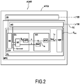
- the ADAS system comprises a central driving unit CD and the ATCS system.
- the central driving unit CD issues the main driving controls of the vehicle, in particular to control acceleration and/or braking, etc, while the ATCS system calculates the assistive torque controls Tc(k).
- Both units are configured to execute programs (in particular programs P1 and P11, for the ATCS system) iteratively at successive loops indexed by an index i.
- the controls Tc(k) issued by the ATCS system are calculated not only based on the behavior of the vehicle itself, but rather based on the behavior of the vehicle altogether with its driver. For this reason, the ATCS system includes a model of the 'vehicle-driver', which represents the physics of the vehicle driven by the driver.
- the MPC solver of the ATCS system can use any dynamic model of the 'vehicle-driver system'.
- this model is represented by two dynamic models: The vehicle model and the steering model.
- model of the vehicle is the simplified model known as the single-track bicycle model.
- the position of the vehicle in particular its lateral position y, is determined with respect to a first, fixed coordinate systems (axes X G and Y G shown on Fig.3 ).
- a second coordinate system (X L , Y L ) is defined. This coordinate system is local and is aligned with the lane on which the vehicle is moving.
- the origin of this local coordinate system is defined based on the position of the vehicle.
- this origin can be the point P of the centreline CL which is closest to the center of mass CoG of the vehicle at the considered time point.
- the orientation of this local coordinate system is based on the orientation of the road at a point defined based on the position of the vehicle.
- the axes (X L , Y L ) are oriented based on the orientation of the lane on which the vehicle is moving at point P, so that vector X L be tangent to the centreline CL at point P.
- a third coordinate system (F x ,F y ) is defined, which is attached to the vehicle: Fx is the vector aligned with the longitudinal, forward direction of the vehicle.
- the motion V and the acceleration a of the vehicle are evaluated relative to this third coordinate system (F x ,F y ).
- the vehicle model also can be the vehicle model disclosed by Reference [5].
- a method or system according to the present disclosure preferably includes a detailed steering model, in which the dynamics of the steering takes into account not only the interaction of the driver when he/she steers the vehicle, but also the dynamics of the steering unit itself.
- the orientation of the front wheels 140 is the result of the different torques applied to the steering column 133: the driver torque DT, the assistive torque Tc and the self-aligning torque Tw.
- the steering dynamics is represented by a two-degree-of-freedom model in which the two degrees of freedom are the steering wheel angle ⁇ sw and the steering column angle, ⁇ sc.
- the steering model based on Ref.[1] is represented on the left part of Fig.4 .
- ⁇ sc ⁇ sw - ⁇ c .
- I arms is the inertia of the arms
- I sw is the inertia of the steering wheel
- Ic is the inertia of the steering transmission (for instance, it represents the inertia of the rack and the front wheels with respect to the pinion, in the case of a rack- and-pinion steering
- T w dF y , f
- the central driving unit (CD) The central driving unit (CD)
- the central driving unit CD is the core data processing unit of the ADAS system.
- it is configured to acquire iteratively the values acquired by the different sensors of the set of sensors 120.
- the central driving unit CD outputs different values, including a number of controls for vehicle 1.
- the central driving unit CD outputs a vector of one or more future reference vehicle state(s) xv r (k+i) of vehicle 1.
- vehicle reference state(s) represent desired vehicle states xv(k+i) of vehicle 1 at successive time point(s) tk+i in the future.
- the prediction horizon of the MPC solver (described in more detail below) is Np, at a time point tk, the future time points at which the future system states are calculated are thus tk+1... tk+Np.
- the vehicle state xv(k) may comprise different variables. For instance, it may comprise the values of the position of the vehicle (longitudinal and lateral deviations x, y), of the heading angle ⁇ , and of the first and second derivatives thereof.
- the ATCS system is implemented by a Model-Predictive Control solver MPC.
- the MPC solver comprises an adaptative optimization unit AO and a Model-Predictive Control Prediction Unit PU.
- the MPC solver is configured to execute the program P iteratively at successive control loops, which will be described below.
- the control loops are executed at successive time points tk, so as to output an assistive torque control value Tc at each time point tk.
- the value Tc calculated at a time point tk is transmitted to the steering actuator 132 so as to apply the calculated desired assistive torque to the steering unit 130 during or at the next time step.
- the prediction unit PU The prediction unit PU
- the adaptative optimization unit AO controls the prediction unit PU to predict a system state xs of the whole vehicle-driver system at the next time point tk+1.
- xs(k) denotes the system state
- ⁇ c(k) is the assist torque rate at time tk, which is the control input of the MPC solver.
- the function f is implemented by the driver torque prediction unit DTP and the vehicle behavior prediction unit VBP.
- the system state xs(k) is a vector of values which represents a state of the vehicle-driver system at a considered time point tk.
- the system state xs may comprise more or fewer values, depending on the vehicle-driver model chosen.
- the above-mentioned global system of coordinates is defined by axes X G and Y G .
- the local, road-aligned coordinate system is defined by axes X L and Y L .
- Reference variables (reference positions, etc.) are denoted by the subscript r .
- the successive lateral positions along the reference trajectory of the vehicle are noted e y,r .
- system state xs comprises the following variables (these variables are relative to the vehicle or to the driver, depending on the context):
- the driver-steering-vehicle state xdsv is the vector composed of the above driver-steering-vehicle variables.
- the driver-steering-vehicle state xdsv may include more of fewer variables than the variables listed above.
- control variable of the MPC solver comprises the assistive torque control rate ⁇ c(k).
- additional control variable(s) may be taken into account as control variable(s) of the MPC solver.
- the prediction function f realized by the prediction unit PU is a compound function realized by the driver torque prediction unit DTP and the vehicle behavior prediction unit VBP, combined within the MPC solver, which will now be described.
- the driver torque prediction unit DTP is configured, based on the perceived state x perceived of the vehicle at a considered time point tk, to predict the driver torque Tact.
- This value Tact of the predicted driver torque is an estimated value of the torque applied by the driver to the steering wheel 131 at the considered time point tk.
- the driver torque prediction unit DTP predicts the driver torque Tact not only on the basis of x perceived , but also on the basis of future reference vehicle state(s) xv r of the vehicle at least at the next time point, or possibly at the next subsequent time points over a time horizon, depending on the implementation.
- a description of a driver torque prediction unit which can be used as a basis to implement a driver torque prediction unit according to the present disclosure can be found in Ref. [1].
- the driver torque prediction unit DTP comprises a sensory unit SU, a cognition unit CU and a neuromuscular response unit NR.
- the sensory unit SU The sensory unit SU
- the function of the sensory unit is to calculate perceived values of variables perceived by the driver, so as to take into account the perception delays caused by his or her sensory organs. These variables include in particular the variables of the perceived state x perceived of the vehicle.
- the calculated delayed values are transmitted to the cognition unit CU.
- the function of the cognition unit CU is to calculate variables ⁇ and ⁇ representative of the intentions of the driver at the considered time point, on the basis of the information (s)he has, that is, the delayed vehicle state value x perceived outputted by the sensory unit SU.
- ⁇ is a variable representative of the driver torque that the driver intends to apply to the steering wheel, while ⁇ is a variable representative of the expected muscle angle that the driver intends to apply to his or her arms, at the current time point tk.
- ⁇ and ⁇ are calculated with a Linear-Quadratic Regulator LQR on the basis predicted values x KF of the state of the vehicle, output by a Kalman filter KF.
- a cognition unit capable of calculating such values ⁇ and ⁇ is for instance disclosed by Ref. [1].
- the cost function of the LQR regulator tends to minimize the differences between the vehicle state xv and the upcoming reference states xv r of the vehicle, over a chosen preview time.
- the cost function may minimize the lateral deviation ey of the vehicle with respect to the 'p' future points of upcoming reference trajectory y r,p of the vehicle on its lane.
- variable ⁇ ⁇ K LQR . x KF y r , p
- K LQR is the LQR gain
- x KF is a vector comprising the estimated variables derived from Ref. [1]
- y r,p a vector containing the lateral position y r of the vehicle at the next 'p' time points, as predicted by the central driving unit CD.
- the estimated variables of vector x KF accordingly include driver-steering-vehicle variables (including in particular the lateral reference target path), driver activation dynamics variables, and reflex dynamics related variables.
- variable ⁇ representative of the expected muscle angle is calculated based on the internal mental model of the driver and the estimated states by the Kalman filter KF.
- the function of the neuromuscular response unit NR is, based on the variables ⁇ and ⁇ outputted by the cognition unit CU, and based on the actual muscle angle of the ⁇ a, to predict the driver torque Tact(k) at the current time point tk.
- the neuro-muscular response unit NR is the same as the neuro-muscular response unit proposed by Ref.[1].
- Tact is calculated by an activation dynamics calculation unit ADC based on the sum of the variable ⁇ and of a value ⁇ r representative of the reflex torque and output by a reflex action calculation unit RAC on the basis of ⁇ .
- the neuromuscular response unit NR can be implemented on the basis of Ref. [1].
- VBP vehicle behavior prediction unit
- the vehicle behavior prediction unit VBP predicts the behavior of the vehicle when the driver torque is applied to its steering wheel.
- the total torque applied to the steering wheel results from the combination of the driver torque DT(k), the assistive torque Tc(k) and the self-aligning torque Tw(k).
- the way these torques add up can be modelled differently depending how it is considered the torques are applied to the steering unit (in particular, in the present model, it is considered that the assistive torque Tc is applied to the steering column, not to the steering wheel).
- the vehicle behavior prediction unit VBP predicts the state xv(k+1) of the vehicle at the next time step based on the total torque applied to the steering wheel and the current state xv(k) of the vehicle.
- the adaptive optimization unit AO The adaptive optimization unit AO
- the adaptive optimization unit AO is configured, at each time point tk, to calculate optimal values of the assistive control torque to be applied by the actuator 132 to the steering column 133, so that the vehicle 1 follows the desired trajectory (as defined by the future reference system states xs r (tk+i) over the period tk+1... tk+Np, where Np is the prediction horizon).
- the optimal future values of the assistive torque are calculated so as to optimize the steering of the vehicle, by minimizing a cost function subject to constraints.
- the optimization takes into account the system state xs(tk) at the start of the considered time window.
- MPC is a finite-horizon optimal control approach that iteratively minimizes a cost function defined for a plant model (the vehicle-driver model) subject to constraints.
- a plant model the vehicle-driver model
- an optimal control sequence composed of system states xs(tk+1)... xs(tNp) within a horizon of Np time steps is computed, subject to constraints.
- only the first element of this sequence is applied to control the plant at the current time and this process will be repeated at the next time step tk+1 , leading to a receding horizon control strategy.
- the length of this finite-time window is called the prediction horizon, Np.
- the control horizon of the control input sequence is set equal to the prediction horizon.
- the MPC solver computes the optimal values in real-time, making it possible to integrate the driver's torque control behavior in the loop, thereby capturing the haptic interaction.
- the MPC solver comprises a driver torque prediction unit, configured to accurately predict the driver torque, it is possible to optimize the control predicted by the MPC solver so as to determine optimal values optimized not only for safety, but also for the comfort of the driver.
- the cost function J MPC comprises terms that tend to minimize a difference, over a time horizon (tk+1...tk+Np), between the vehicle state of the vehicle xv and the reference vehicle state xv r .
- the cost function J may further be based on part or on all of the following additional terms:
- the system state reference vector xs r which, for each variable, defines the desired value of the variable, is defined based on the systems requirements and the goal of the assistive torque calculation method.
- the tracking performance objective is usually to minimize the lateral deviation e y with respect to the reference trajectory y r .
- This reference trajectory is normally defined as the lane centerline CL of the driving vehicle lane, which means that the reference position y r of the vehicle is at the center of the lane.
- the optimization performed by the MPC solver is preferably performed (depending on the considered variables) only within a look-ahead distance from the vehicle, for instance depending on the vehicle velocity and the heading angle ⁇ .
- the optimal torque calculated by the MPC solver results in a vehicle lateral position y which is very often at the center of lane, but in some cases is only close to it, because the MPC solver also takes into account other variables, e.g. the driver intention etc.
- the reference assistive torque can be either zero or the real driver torque DT(k).
- the driving comfort is enhanced through weights which bear on the lateral velocity Vy and the yaw rate ⁇ .
- the cost function J MPC can also include terms related to the driver's effort or discomfort so as to reduce the activation of the muscle spindles' torque or the total driver steering torque and consequently, so as to improve the driver's comfort during driving.
- the cost function is adaptative.
- the algorithm indeed is tuned to the driver by changing the above-mentioned weights of the cost function.
- This dynamic adaptation aims at minimising conflicts between the applied driver torque DT and the assistive torque Tc, as well as dynamically sharing the control authority.
- the calculation method is performed as follows (In reference to Fig.5 ).
- step S10 the algorithm starts back at step S10 at the next time step.
- step S50 the weights of the cost function J MPC are adapted, in order to find a more appropriate level of authority between the driver and the ATCS system.
- step S50 is triggered at step S40 when a difference between the two torques is detected only if said difference is above a threshold.
- the weights are adapted based on the sign difference and/or based on the difference between the actual driver torque (DTk) and the assistive torque.
- the new weights can be found using a predetermined look-up table in which possible values of the weights of the cost function J MPC are recorded.
- the adaptation of the weights is preferably carried out in a smooth way to avoid any abrupt torque feedback to the driver.
Landscapes
- Engineering & Computer Science (AREA)
- Chemical & Material Sciences (AREA)
- Combustion & Propulsion (AREA)
- Transportation (AREA)
- Mechanical Engineering (AREA)
- Steering Control In Accordance With Driving Conditions (AREA)
Abstract
Description
- The present disclosure concerns the calculation of the value of an assistive torque applied to the steering column of a vehicle by an Advanced Driver Assistance System (ADAS), in addition to the torque applied by the driver of the vehicle him- or herself during driving.
- An ADAS refers herein to an Advanced Driver Assistance System. Such systems aim to increase safety and to reduce the mental workload of the driver during driving.
- Among ADAS, some systems include a function of applying an additional torque to the steering column during driving, to facilitate driving.
- In this case, the driving authority is shared between the driver and the ADAS. Since the torque applied by the driver is unknown, it is difficult to determine the optimal or even a proper value for the assistive torque. In some embodiments, the assistive torque applied by the ADAS has been found to be too weak; in others, too strong; the value of the assistive torque has also been found to be inconsistent.
- In addition, it can sometimes oppose the driver intention, and this conflict can be perceived as intrusive and unnatural, which results in sub-optimal guidance and reduced driver comfort.
- Accordingly, there is still a need for a calculation method which would provide consistently proper values for the assistive torque applied by an ADAS to the steering column of the vehicle, thereby significantly increasing tracking performance and safety as well as increasing the pleasure of driving for the driver.
- The references below disclose systems and methods that have been developed in the field of assistive torque calculation or merely driver torque estimation or modelling.
-
- [1] T. Niu and D. Cole, "A model of driver steering control incorporating steering torque feedback and state estimation" Department of Engineering, University Cambridge, Tech. Rep., 2020, Technical Report ENG-TR 005.
- [2] C. J. Nash and D. J. Cole, "Identification and validation of a driver steering control model incorporating human sensory dynamics" Vehicle System Dynamics, vol. 58, no. 4, pp. 495-517, 2020. Report ENG-TR 005.
- [3] R. S. Sharp and V. Valtetsiotis, "Optimal preview car steering control" Vehicle System Dynamics, vol. 35, pp. 101-117, 2001.
- [4] Wang, L. "Model Predictive Control System Design and Implementation Using MATLAB®". Springer, London, 2009.
- [5] Rajamani, R. "Vehicle dynamics and control". New York: Springer, 2012.
- In order to address the above-described problems of existing assistive torque calculation methods, the following method is proposed. This method is a computer-implemented assistive torque calculation method for calculating an assistive torque to be applied to a steering unit of a vehicle by a driver assistance system (ADAS) of the vehicle, in addition to a driver torque applied to the steering unit by a driver of the vehicle.
- This method comprises the steps of:
- S12) determining optimal values of the assistive torque over a time horizon by minimizing a cost function, based on desired reference system states of the vehicle-driver system at future time point(s), using an MPC solver (Model Predictive Control solver); and
- S14) outputting the optimal value determined for the next time point; wherein
- the steering torque for orienting wheel(s) of the vehicle results at least from the driver torque and the assistive torque;
- the MPC solver determines the optimal values using a prediction unit comprising a driver torque prediction unit and a vehicle behaviour prediction unit;
- the driver torque prediction unit being configured to calculate a predicted driver torque based at least on a perceived state xperceived of the vehicle related to a position of the vehicle, and on one or more reference vehicle state(s) of the vehicle at one or more future time points;
- the vehicle behaviour prediction unit being configured, based on the predicted driver torque, on a measured driver-steering-vehicle state of the vehicle-driver system for a current time point, and optionally on future reference vehicle state(s) at one or more future time points, to output an estimated driver-steering-vehicle state of the vehicle at the next time point.
- In the present document:
- When a noun is written followed by '(s)', it means that the considered object or item can be in the singular or plural form. For instance, the expression 'object(s)' means 'at least one object'. Accordingly, a sentence like 'Object(s) are present' includes the singular form, that is, it encompasses the case where a single object is present.
- a variable X at a time point tk may be interchangeably noted Xk or X(k)
- a function or variable 'based on a value' or 'calculated from a value' means that at least said value is used to calculate the variable or the output of the function (the variable or the output of the function is often also a function of other values).
- a state is a vector.
- a vector 'related' to a variable means that component(s) of the vector are based on the value of said variable. For instance, in the above method, component(s) of the perceived state xperceived are variable(s) based on the position of the vehicle.
- 'minimizing a variable' means minimizing a norm of the variable. It further means either minimizing, or also maximizing the norm of the variable, depending on the context or the implementation.
- In the above-defined method, the vehicle-driver system is the system composed of the driver and the vehicle, when the driver is driving the vehicle.
- The MPC solver determines the optimal values based on the system state, which describes this system.
- The system state is composed of variables calculated by the prediction unit, i.e., by the driver torque prediction unit DTP and the vehicle behaviour prediction unit.
- The system state includes at least variable(s) related to the tracking (the successive positions over time) of the vehicle. These positions may include for instance the lateral position of the vehicle relative to the centerline of the lane on which it is moving, and the yaw angle of the vehicle.
- The system state may further also include variable(s) related to the driver, such as the driver torque, to capture the intention of the driver.
- The driver-steering-vehicle variables are the main variables which describe the physics of the vehicle-driver system.
- In the general context of the present disclosure, the driver-steering-vehicle state xdsv may include at least variable(s) related to the position of the vehicle (and derivatives thereof), (e.g. the lateral position and yaw angle of the vehicle), as well as variable(s) related to the steering system coupled to the driver arms (e.g., the steering wheel angle).
- The system state comprises at least the driver-steering-vehicle state.
- In addition, the vehicle state xv is a vector comprising variable(s) related to the vehicle dynamics: Its position, yaw angle, lateral acceleration, etc.
- The yaw angle of the vehicle is herein the angle between the longitudinal direction of the vehicle and a global x-axis (respectively noted FX and XG below).
- In some embodiments, as component(s) based on the position of the vehicle, the perceived state xperceived may comprise a lateral position of the vehicle relative to a centerline of the lane or road on which it is moving and/or a lateral error between an actual lateral position of the vehicle and a desired reference lateral position of the vehicle.
- In some embodiments, the perceived state xperceived may comprise at least one of the yaw angle of the vehicle, and variable(s) related to the driver, such as a muscle angle of arms of the driver.
- Advantageously, thanks to the presence of the driver torque prediction unit and the vehicle behavior unit, an accurate prediction of the future system states of the vehicle-driver system can be made by the MPC solver. On this basis, a variety of controls can be performed, making it possible to finely adapt the magnitude of the assistive torque to the individual characteristics of the driver. Consequently, a smooth cooperation between the driver and the driver assistance system (ADAS) can be achieved.
- The muscle angle of the arms of the driver has the usual meaning in driver-vehicle dynamics, namely a mathematical one degree-of-freedom representation of the human arms (lumped) pivoting at the shoulder (as used for instance in References [1] and [2]).
- In some embodiments, the cost function comprises terms that tends to minimize a difference, over a time horizon, between component(s) of the system state and reference values for said component(s).
- In some variants of the above embodiments, the terms of the cost function are based on at least one of the following component(s) of the system state:
- vehicle-related component(s), such as a lateral deviation or a yaw angle of the vehicle,
- driver-comfort related component(s), such as a lateral velocity or a yaw rate of the vehicle,
- driver-activity related component(s), such as the driver predicted torque or a reflex torque applied by the driver to the steering unit, and
- assistive-torque-related component(s).
- For each of the component(s) that are taken into account in the cost function, the cost function can be based on the value of the variable, its magnitude and/or its rate of change.
- In particular, by taking into account, in the cost function of the MPC solver, terms related to the torque applied by the driver, it is possible to calculate values of the assistive torque which advantageously not only ensure that the vehicle is driven safely, but also to provide an improved driving feeling for the driver, and consequently a better driving experience.
- For instance, by minimizing the predicted driver torque, the driver steering effort can be reduced; and by minimizing a calculated reflex torque, an intuitive, comfortable assistance can be provided by the driver assistance system, since the reflex torque is directly linked to the presence of uncertainties and discomfort.
- In some embodiments, the driver torque prediction unit comprises a sensory unit, a cognition unit and a neuromuscular response unit;
- The sensory unit is configured to calculate the perceived state xperceived of the vehicle.
- The cognition unit is configured, based on the perceived state of the vehicle xperceived, to calculate a value α representative of an expected driver torque and a value γ representative of an expected muscle angle of the arms of the driver, for the current time point.
- The neuromuscular response unit is configured, based on said values α and γ, and on the current value of the muscle angle (θa) of the arms of the driver, to calculate the predicted driver torque at the next time point.
- The role of the cognition unit is to predict the value α representative of the expected driver torque which corresponds to the driver behaviour. The neuromuscular response unit accounts for the muscle dynamics of the arms, and the sensory unit takes into account the perception faculties of the driver.
- In some variants of the above embodiments, the cognition unit comprises a Kalman filter and an optimal controller.
- The Kalman filter is configured, based on the perceived state xperceived of the vehicle at the current time point and on the value α representative of a driver torque expected at a prior time point, to calculate an estimate x̂KF of a state of the vehicle.
- The optimal controller is configured, based on the state estimate x̂KF,k at the current time point calculated by the Kalman filter, to calculate a value of the variable α representative of the expected driver torque for the current time point by minimizing a cost function.
- In these variants, the optimal controller may be a linear quadratic regulator or a model predictive control.
- In these variants, based on the perceived state xperceived of the vehicle, the Kalman filter calculates an estimate x̂KF of the states of the arms-steering-vehicle model, represented in an internal mental representation that the driver has based on experience.
- In some embodiments comprising a neuromuscular response unit, the neuromuscular response unit is configured to calculate a value α r representative of a reflex torque based on the value γ representative of an expected muscle angle of the arms of the driver and on the current value of the muscle angle; and to calculate the driver torque at the current time point based on the values α and α r representative respectively of the expected driver torque and of the reflex torque.
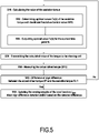
- In some embodiments, the cost function is an adaptive cost function with varying weights, and the assistive torque calculation method further comprises:
- S30) measuring the actual driver torque;
- S40) detecting a difference and/or a sign difference between the actual driver torque and the assistive torque;
- S50) updating the varying weights of the cost function when the sign difference has been detected and/or based on the difference between the actual driver torque and the assistive torque.
- Thanks to the adaptive cost function defined above, the torque conflicts between the driver torque and the assist torque that may arise can be smoothly tackled by the driver assistance system, and in most cases avoided. These adaptive characteristics of the cost function enhance collaboration and allow for dynamic allocation of the level of control authority between the driver and the driver assistance system.
- The present disclosure further encompasses a driver assistance method for assisting a driver of a vehicle, wherein the method comprises iteratively, while the vehicle is being driven by the driver:
- S10) calculating a value of an assistive torque by the above-proposed assistive torque calculation method; and
- S20) transmitting the calculated value of the assistive torque to a steering unit of the vehicle; and wherein,
- The proposed driver assistance method is preferably executed continuously while the vehicle is being driven by the driver.
- It can be executed in particular during whole trips, regardless of any alarm signals that are possibly emitted and regardless of the driving circumstances (for instance, regardless of whether the vehicle is moving along a same lane or is performing a lane change).
- In a particular implementation, the proposed method is determined by computer program instructions.
- Accordingly, another purpose the present disclosure is to propose one or more computer program(s) comprising instructions which, when the instructions are executed by a computer, cause the computer to carry out the steps of one of the above-defined methods, in accordance with the present disclosure. The computer program(s) may use any programming language, and be in the form of source code, object code, or code intermediate between source code and object code, such as in a partially compiled form, or in any other desirable form. The computer may be any data processing means, for instance one or more personal computer(s), one or more processors, one or more remote servers, etc. It can be made up of a single machine or a plurality of machines, for instance spread over different locations.
- The present disclosure also includes a non-transitory computer readable medium, having the one or more above-defined computer program(s) stored thereon. The computer-readable medium may be an entity or device capable of storing the program. For example, the computer-readable medium may comprise storage means, such as a read only memory (ROM), e.g. a compact disk (CD) ROM, or a microelectronic circuit ROM, or indeed magnetic recording means, e.g. a floppy disk or a hard disk.
- The present disclosure also includes a computer-implemented assistive torque calculation system for calculating an assistive torque to be applied to a steering unit of a vehicle by a driver assistance system of the vehicle; the assistive torque calculation system comprising one or more processors and a computer-readable medium; the computer-readable medium comprising computer instructions stored therein, wherein the instructions, when executed by the one or more processors, cause the one or more processors to carry out the steps of any one of the above-defined assistive torque calculation methods.
- The present disclosure also includes an advanced driver assistance system, comprising one or more processors and a computer-readable medium;
the computer-readable medium comprising computer instructions stored therein, wherein the instructions, when executed by the one or more processors, cause the one or more processors to carry out the steps of any one of the above-mentioned driver assistance methods. - The present disclosure can be implemented in any kind of human-driven vehicle. It therefore further includes a vehicle comprising the above-defined assistive torque calculation system or the above-defined advanced driver assistance system.
- The present invention may be better understood and its numerous other objects and advantages will become apparent to those skilled in the art by reference to the accompanying drawing wherein like reference numerals refer to like elements in the several figures and in which:
-
Fig.1 is a schematic representation in top view of a vehicle equipped with an assistive torque calculation system according to the present disclosure; -
Fig.2 is a schematic functional representation of the assistive torque calculation system mounted in the vehicle ofFig.1 ; -
Fig.3 is a schematic representation in top view of a scene in which the vehicle ofFig.1 is moving; -
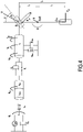
Fig.4 is a schematic representation of the assistive torque calculation system mounted in the vehicle ofFig.1 ; and -
Fig.5 is a block diagram representing an embodiment of a driver assistance method for assisting a driver to drive a vehicle according to the present disclosure. - An advanced driver assistance system ADAS (hereafter, 'ADAS') comprising an assistive torque calculation system ATCS according to the present disclosure will now be presented.
- The structure of the ADAS system is illustrated by
Fig.1 , while its functional units are illustrated byFig.2 . On these figures, ADAS is presented in operation, mounted on a vehicle 1. The vehicle 1 is a car, which represents a non-limiting example of a vehicle on which a system according to the present disclosure can be mounted. The vehicle 1 is represented inFig.3 moving on a road, more precisely moving on the right lane of the road. The centerline of the lane on which vehicle 1 is moving is noted CL. - The vehicle 1 includes the advanced driver assistance system ADAS.
- The ADAS system comprises a central driving computer 110 ('computer 110'), a set of
sensors 120, each sensor being connected tocomputer 110, asteering unit 130,front wheels 140,rear wheels 150, and various other components. - Most components of the ADAS system are shared components, which are used to perform multiple tasks. That is, the components of the ADAS system perform the functions of the ADAS system, but may also perform other functions in vehicle 1. The ADAS system includes in particular, as mentioned above, an assistive torque calculation system ATCS according to the present disclosure, which is essentially constituted by the
computer 110. - Although
computer 110 is represented onFig.1 in a single box, it may comprise one or more processors, and can therefore be a distributed calculation system, distributed over a plurality of processors, possibly physically arranged on different locations. - The
steering unit 130 comprises asteering wheel 131, anactuator 132 and asteering column 133. - The set of
sensors 120 comprises in particular sensors configured to perceive an external environment of car 1. In this purpose, it comprises several cameras. One of these cameras, thefront camera 121 is represented onFig.1 . - The set of
sensors 120 further comprises a steering wheel orientation-meter 122, which measures the orientation or angle θsw of thesteering wheel 131, and atorque meter 123 which measures the driver torque DTk applied by the driver to the steering wheel. In some embodiments, other variables may be measured, in particular the steering column angle θsc. The values outputted by thewheel orientation meter 122 and by thetorque meter 123 are transmitted in real time tocomputer 110. - During driving, in order to steer car 1, the driver D of car 1 applies a driver torque DTk (at a time point tk) to the
steering wheel 131. At the same time, the ATCS transmits the next desired value of the assistive torque control Tc(k+1) to theactuator 132. - Based on this control, the
actuator 132 applies an additional assistive torque having the desired value Tc(k+1) to thesteering column 133. Thesteering column 133, which is also submitted to its own self-aligning torque Tw(k), rotates (or not) to orient the wheels of the vehicle under the cumulated torque resulting from the driver torque DT, the assistive torque Tc and the self-aligning torque Tw, and orients thefront wheels 140 accordingly. - The functions (the functional units) of the ADAS system, and in particular of the ACST system, are implemented on the
computer 110. -
Computer 110 comprises anon-transitory storage medium 111 and one or more processor(s) 112. - The
computer 110, in particular in itsstorage medium 111, stores instructions which when executed by the one or more processor(s) 112 cause the one or more processor(s) 112 to implement the different functional units or functions of the ADAS system, and in particular of the ACST system. - The one or
more processors 112 are intended to be representative of the presence of any one or more processors or processing devices, of any of a variety of forms. - A computer program P1 to perform driver assistance tasks and/or driving tasks, which includes in particular a sub-program P11 to calculate an assistive torque, according to the present disclosure, is stored in
storage medium 111. This program, and thestorage medium 111, are examples respectively of a computer program and a computer-readable recording medium pursuant to the present disclosure. - The
storage medium 111 of thecomputer 110 indeed constitutes a recording medium according to the invention, readable by the one or more processor(s) 112 and on which said program is recorded. - The ADAS system comprises a central driving unit CD and the ATCS system. The central driving unit CD issues the main driving controls of the vehicle, in particular to control acceleration and/or braking, etc, while the ATCS system calculates the assistive torque controls Tc(k).
- Both units are configured to execute programs (in particular programs P1 and P11, for the ATCS system) iteratively at successive loops indexed by an index i. The successive loops i are executed at successive time points ti (i=1.... i=k).
- The controls Tc(k) issued by the ATCS system are calculated not only based on the behavior of the vehicle itself, but rather based on the behavior of the vehicle altogether with its driver. For this reason, the ATCS system includes a model of the 'vehicle-driver', which represents the physics of the vehicle driven by the driver.
- While remaining within the scope of the present disclosure, the MPC solver of the ATCS system can use any dynamic model of the 'vehicle-driver system'.
- In the present embodiment, this model is represented by two dynamic models: The vehicle model and the steering model.
- In the present embodiment the model of the vehicle is the simplified model known as the single-track bicycle model.
- The position of the vehicle, in particular its lateral position y, is determined with respect to a first, fixed coordinate systems (axes XG and YG shown on
Fig.3 ). - A second coordinate system (XL, YL) is defined. This coordinate system is local and is aligned with the lane on which the vehicle is moving.
- The origin of this local coordinate system is defined based on the position of the vehicle. For instance, as in the present embodiment, this origin can be the point P of the centreline CL which is closest to the center of mass CoG of the vehicle at the considered time point.
- The orientation of this local coordinate system (XL, YL) is based on the orientation of the road at a point defined based on the position of the vehicle. For instance, as in the present embodiment, the axes (XL, YL) are oriented based on the orientation of the lane on which the vehicle is moving at point P, so that vector XL be tangent to the centreline CL at point P.
- A third coordinate system (Fx,Fy) is defined, which is attached to the vehicle: Fx is the vector aligned with the longitudinal, forward direction of the vehicle.
- The motion V and the acceleration a of the vehicle are evaluated relative to this third coordinate system (Fx,Fy).
- The vehicle model is based on the equations below, which represent the linearised motion of the vehicle:


front wheels 140 and the rear wheels 150 (i standing for f or r, respectively for the front and the rear axle), in the direction FY perpendicular to the hubs of the wheels; Izz is the inertia with respect to the centre of mass; ψ is the heading angle and ψ̈ is its second derivative; and lf and lr are the front and rear distance from the centre of gravity CoG. - In addition, in the model, the lateral axle forces Fy,i have a linear relation with respect to the slip angles αi, and are calculated as:


- In these equations, αf and αr represent the lateral tire slip angle and are obtained by:


- The vehicle model also can be the vehicle model disclosed by Reference [5].
- In order to accurately calculate the predicted driver torque Tact, a method or system according to the present disclosure preferably includes a detailed steering model, in which the dynamics of the steering takes into account not only the interaction of the driver when he/she steers the vehicle, but also the dynamics of the steering unit itself.
- In the vehicle 1 of the present embodiment, the orientation of the
front wheels 140 is the result of the different torques applied to the steering column 133: the driver torque DT, the assistive torque Tc and the self-aligning torque Tw. - In embodiments of the proposed methods, and in particular in this embodiment, the steering dynamics is represented by a two-degree-of-freedom model in which the two degrees of freedom are the steering wheel angle θsw and the steering column angle, θsc.
- In the present embodiment, the steering model, based on Ref.[1], is represented on the left part of
Fig.4 . - The difference of the angles of the steering wheel and the steering column at the steering column is defined as Δθsc = θsw - θc.
- Its derivative is calculated as:

- The interaction of the driver is taken into account through the introduction of the muscle angle θa of the arms of the driver, interacting with the
steering wheel 121. The dynamic behaviour of the driver steering the steering unit is defined by the equations:

- Based on the predicted driver torque Tact, the muscle angle θa is calculated using the equation:

- Moreover, the road wheel angle is calculated proportionally to the steering angle column, with a steering gear ratio G:

- The torque generated about the king-pin axes is (d being the pneumatic trail):

- A similar steering model is proposed by Ref.[1].
- The central driving unit CD is the core data processing unit of the ADAS system.
- As in input, it is configured to acquire iteratively the values acquired by the different sensors of the set of
sensors 120. - On this basis, at each time point tk, the central driving unit CD outputs different values, including a number of controls for vehicle 1.
- Among the outputted values, at a time point tk, the central driving unit CD outputs a vector of one or more future reference vehicle state(s) xvr(k+i) of vehicle 1. These vehicle reference state(s) represent desired vehicle states xv(k+i) of vehicle 1 at successive time point(s) tk+i in the future.
- Based on these values, if the prediction horizon of the MPC solver (described in more detail below) is Np, at a time point tk, the future time points at which the future system states are calculated are thus tk+1... tk+Np.
- Depending on the implementation, the vehicle state xv(k) may comprise different variables. For instance, it may comprise the values of the position of the vehicle (longitudinal and lateral deviations x, y), of the heading angle ψ, and of the first and second derivatives thereof.
- The ATCS system is implemented by a Model-Predictive Control solver MPC.
- The MPC solver comprises an adaptative optimization unit AO and a Model-Predictive Control Prediction Unit PU.
- The MPC solver is configured to execute the program P iteratively at successive control loops, which will be described below. The control loops are executed at successive time points tk, so as to output an assistive torque control value Tc at each time point tk. The value Tc calculated at a time point tk is transmitted to the
steering actuator 132 so as to apply the calculated desired assistive torque to thesteering unit 130 during or at the next time step. - At each control loop, the adaptative optimization unit AO controls the prediction unit PU to predict a system state xs of the whole vehicle-driver system at the next time point tk+1.
- As known per se, the general structure of the prediction model is:

- Where xs(k) denotes the system state, and Ṫc(k) is the assist torque rate at time tk, which is the control input of the MPC solver. By using the torque rate as a control input of the MPC solver, the value of the assistive torque Tc can be controlled.
- In the present embodiment, the function f is implemented by the driver torque prediction unit DTP and the vehicle behavior prediction unit VBP.
- The system state xs(k) is a vector of values which represents a state of the vehicle-driver system at a considered time point tk. The system state xs may comprise more or fewer values, depending on the vehicle-driver model chosen.
- In the present embodiment, the above-mentioned global system of coordinates is defined by axes XG and YG.
- The local, road-aligned coordinate system is defined by axes XL and YL.
- Reference variables (reference positions, etc.) are denoted by the subscript r. For instance, the successive lateral positions along the reference trajectory of the vehicle are noted ey,r.
- The system state xs is the vector:

- That is, the system state xs comprises the following variables (these variables are relative to the vehicle or to the driver, depending on the context):
- 1) Driver-steering-vehicle variables:
- y
- Lateral position (m) of the vehicle along axis YG;
- Vy
- Lateral velocity (m/s) (along lateral direction FY)
- ψ
- Yaw angle (or Heading angle) of the vehicle (rad)
- ψ̇
- Yaw rate (rad/s)
- θsw
- Steering wheel angle (rad)
- θ̇sw
- Steering wheel rate of rotation (rad/s)
- θsc
- Steering column angle (rad)
- θ̇sc
- Steering column rate of rotation (rad/s)
- θα
- Muscle angle of the arms of the driver (lumped) (rad)
- In this embodiment, the driver-steering-vehicle state xdsv is the vector composed of the above driver-steering-vehicle variables.
- The driver-steering-vehicle state xdsv may include more of fewer variables than the variables listed above.
- 2) Driver activation dynamics variables:
- TAct
- Predicted driver torque (Nm)
- 3) Sensory-organs-delayed variables:
- ey
- Lateral error (m): the difference (vector) between the lateral position y and the reference lateral position yr, perceived by the driver
- eyd
- Delayed lateral error (m)
- ψd
- Delayed yaw angle (rad)
- θad
- Delayed muscle angle (rad)
- 4) Kalman filter variables:
- xKF
- Vector of variables constituting the Kalman Filter state, estimated by the Kalman filter of the cognition unit CU.
- 5) Expected (or ideal) Muscle angle-related variables:
- γ
- variable representative of the expected muscle angle of the driver (rad)
- 6) LQR - Driver control input-related variable:
- α
- Variable representative of the expected driver torque (Nm)
- 7) Reflex Dynamics related variables:
- αr
- Variable representative of the expected reflex torque, that is, the reflex torque applied by the muscle spindles of the driver's arms (Nm)
- 8) Control input relative variables:
- Tc
- the assistive torque (Nm)
- In embodiments of the present method, an in particular in the present embodiment, the control variable of the MPC solver comprises the assistive torque control rate Ṫc(k).
- In some embodiments, additional control variable(s) may be taken into account as control variable(s) of the MPC solver.
- The prediction function f realized by the prediction unit PU is a compound function realized by the driver torque prediction unit DTP and the vehicle behavior prediction unit VBP, combined within the MPC solver, which will now be described.
- A more comprehensive description of the general background of the MPC framework, which can be used to implement the MPC solver of the present disclosure, can be found in Ref.[4] .
- The driver torque prediction unit DTP is configured, based on the perceived state xperceived of the vehicle at a considered time point tk, to predict the driver torque Tact. This value Tact of the predicted driver torque is an estimated value of the torque applied by the driver to the
steering wheel 131 at the considered time point tk. - In this embodiment, the driver torque prediction unit DTP predicts the driver torque Tact not only on the basis of xperceived, but also on the basis of future reference vehicle state(s) xvr of the vehicle at least at the next time point, or possibly at the next subsequent time points over a time horizon, depending on the implementation.
- A description of a driver torque prediction unit which can be used as a basis to implement a driver torque prediction unit according to the present disclosure can be found in Ref. [1].
- In the present embodiment, in order to predict the driver torque, the driver torque prediction unit DTP comprises a sensory unit SU, a cognition unit CU and a neuromuscular response unit NR.
- The function of the sensory unit is to calculate perceived values of variables perceived by the driver, so as to take into account the perception delays caused by his or her sensory organs. These variables include in particular the variables of the perceived state xperceived of the vehicle.
- The calculated delayed values are transmitted to the cognition unit CU.
- The function of the cognition unit CU is to calculate variables α and γ representative of the intentions of the driver at the considered time point, on the basis of the information (s)he has, that is, the delayed vehicle state value xperceived outputted by the sensory unit SU.
- α is a variable representative of the driver torque that the driver intends to apply to the steering wheel, while γ is a variable representative of the expected muscle angle that the driver intends to apply to his or her arms, at the current time point tk.
- The values of α and γ are calculated with a Linear-Quadratic Regulator LQR on the basis predicted values xKF of the state of the vehicle, output by a Kalman filter KF.
- A cognition unit capable of calculating such values α and γ is for instance disclosed by Ref. [1].
- However, in contrast with the cognition unit disclosed by Ref. [1], the cost function of the LQR regulator tends to minimize the differences between the vehicle state xv and the upcoming reference states xvr of the vehicle, over a chosen preview time. For instance, the cost function may minimize the lateral deviation ey of the vehicle with respect to the 'p' future points of upcoming reference trajectory yr,p of the vehicle on its lane.
- Examples of cost functions that can be used by the Linear-Quadratic Regulator LQR are proposed by Ref. [2] and [3].
- Finally, the variable α is calculated as:

- The estimated variables of vector xKF accordingly include driver-steering-vehicle variables (including in particular the lateral reference target path), driver activation dynamics variables, and reflex dynamics related variables.
- In addition, the variable γ representative of the expected muscle angle is calculated based on the internal mental model of the driver and the estimated states by the Kalman filter KF.
- The function of the neuromuscular response unit NR is, based on the variables α and γ outputted by the cognition unit CU, and based on the actual muscle angle of the θa, to predict the driver torque Tact(k) at the current time point tk.
- The neuro-muscular response unit NR is the same as the neuro-muscular response unit proposed by Ref.[1]. Tact is calculated by an activation dynamics calculation unit ADC based on the sum of the variable α and of a value αr representative of the reflex torque and output by a reflex action calculation unit RAC on the basis of γ.
- The neuromuscular response unit NR can be implemented on the basis of Ref. [1].
- In the prediction unit PU, after the driver torque prediction unit has predicted a driver torque Tact for the current step, the vehicle behavior prediction unit VBP predicts the behavior of the vehicle when the driver torque is applied to its steering wheel. The total torque applied to the steering wheel results from the combination of the driver torque DT(k), the assistive torque Tc(k) and the self-aligning torque Tw(k). The way these torques add up can be modelled differently depending how it is considered the torques are applied to the steering unit (in particular, in the present model, it is considered that the assistive torque Tc is applied to the steering column, not to the steering wheel).
- Based on the vehicle model presented above, the vehicle behavior prediction unit VBP predicts the state xv(k+1) of the vehicle at the next time step based on the total torque applied to the steering wheel and the current state xv(k) of the vehicle.
- In the MPC solver, the adaptive optimization unit AO is configured, at each time point tk, to calculate optimal values of the assistive control torque to be applied by the
actuator 132 to thesteering column 133, so that the vehicle 1 follows the desired trajectory (as defined by the future reference system states xsr(tk+i) over the period tk+1... tk+Np, where Np is the prediction horizon). - These optimal values are calculated using a Model-Predictive Control algorithm.
- According to such algorithm, the optimal future values of the assistive torque are calculated so as to optimize the steering of the vehicle, by minimizing a cost function subject to constraints. The optimization takes into account the system state xs(tk) at the start of the considered time window.
- MPC is a finite-horizon optimal control approach that iteratively minimizes a cost function defined for a plant model (the vehicle-driver model) subject to constraints. At each time point tk, an optimal control sequence composed of system states xs(tk+1)... xs(tNp) within a horizon of Np time steps is computed, subject to constraints. However, only the first element of this sequence is applied to control the plant at the current time and this process will be repeated at the next time step tk+1 , leading to a receding horizon control strategy.
- The length of this finite-time window is called the prediction horizon, Np. The control horizon of the control input sequence is set equal to the prediction horizon.
- The MPC solver computes the optimal values in real-time, making it possible to integrate the driver's torque control behavior in the loop, thereby capturing the haptic interaction.
- Since the MPC solver comprises a driver torque prediction unit, configured to accurately predict the driver torque, it is possible to optimize the control predicted by the MPC solver so as to determine optimal values optimized not only for safety, but also for the comfort of the driver.
- In order to optimize safety, the cost function JMPC comprises terms that tend to minimize a difference, over a time horizon (tk+1...tk+Np), between the vehicle state of the vehicle xv and the reference vehicle state xvr.
- In addition, in order to optimize the comfort of the driver during driving, the cost function J may further be based on part or on all of the following additional terms:
- terms that tend to minimize, over the time horizon (tNp), a magnitude and/or a rate of change of the assistive torque Tc(k);
- terms that tend to minimize, over the time horizon (tNp), the magnitude of the predicted driver torque Tact(k) and/or of the predicted driver steering angle θd ;
- terms that tend to minimize, over the time horizon (tNp), the difference between the assistive torque Tc(k) and the driver torque DT(k).
- For instance, in the assistive torque calculation system ATCS of the present embodiment, the cost function for instance is defined as:

- Wx, WxN are the weighting matrices of the stage and terminal cost for the states, which give more or less relative importance to the terms of the cost function.
- WTc is the stage cost for the input, that is, for the rate of the assistive torque Tc.
- xsr,k is the system state reference vector at time tk
- Tc (k) is the rate of the assistive torque at time point tk and Ṫc r (k) is the corresponding reference value.
- The system state reference vector xsr which, for each variable, defines the desired value of the variable, is defined based on the systems requirements and the goal of the assistive torque calculation method.
- In the above cost function JMPC, first of all, the tracking performance objective is usually to minimize the lateral deviation ey with respect to the reference trajectory yr. This reference trajectory is normally defined as the lane centerline CL of the driving vehicle lane, which means that the reference position yr of the vehicle is at the center of the lane.
- The optimization performed by the MPC solver is preferably performed (depending on the considered variables) only within a look-ahead distance from the vehicle, for instance depending on the vehicle velocity and the heading angle ψ.
- Since the optimization performed by the MPC solver is based on many variables (the variables taken into account in the cost function JMPC) and not just the lateral deviation, the optimal torque calculated by the MPC solver results in a vehicle lateral position y which is very often at the center of lane, but in some cases is only close to it, because the MPC solver also takes into account other variables, e.g. the driver intention etc.
- In practice, most variables of the reference system state xsr are often set to 0, in order to minimize the magnitude of these variables.
- Regarding the assistive torque Tc, the reference assistive torque can be either zero or the real driver torque DT(k).
- Moreover, the driving comfort is enhanced through weights which bear on the lateral velocity Vy and the yaw rate ψ̇.
- The cost function JMPC can also include terms related to the driver's effort or discomfort so as to reduce the activation of the muscle spindles' torque or the total driver steering torque and consequently, so as to improve the driver's comfort during driving.
- In addition, in order to better capture the specific needs or specific driving features of each driver, the cost function is adaptative. The algorithm indeed is tuned to the driver by changing the above-mentioned weights of the cost function. This dynamic adaptation aims at minimising conflicts between the applied driver torque DT and the assistive torque Tc, as well as dynamically sharing the control authority.
- In this purpose, the calculation method is performed as follows (In reference to
Fig.5 ). - During normal driving of the vehicle by the driver, the following steps are carried out iteratively:
- S10) calculating a value of an assistive torque by the assistive torque calculation method described above. This includes, in the present embodiment:
- S12) determining optimal values (Tc(k)) of the assistive torque over a time horizon (Np) by minimizing the cost function (JMPC), based on desired reference states xsr,k of the vehicle at future time point(s) (tk+1...tk+Np), using the Model Predictive Control solver MPC;
- S14) outputting the optimal value (Tc) determined for the next time point (tk+1).
- S20) transmitting the calculated value Tc(k+1) of the assistive torque to the steering unit of the vehicle; upon receiving the calculated value of the assistive torque, the
steering unit 130 controls itsactuator 132 to apply the assistive torque having the calculated value Tc to thesteering column 133. Thesteering unit 130 is further configured so that the driver receives via the steering wheel 131 a haptic feedback on the assistive torque Tc applied by theactuator 132. - S30) the actual driver torque (DTk) is measured by the
torque meter 123; - S40) it is detected whether there is a sign difference between the actual driver torque DTk and the assistive torque Tck, and/or detecting the difference between these two torques values ("detecting a difference' means herein measuring the value of the difference).
- If no difference is detected, the algorithm starts back at step S10 at the next time step.
- Conversely, if a difference and/or a sign difference is detected, it is concluded that some conflict exists between the assistive torque and the torque applied by the driver has been detected; consequently, a step S50 is executed:
S50) the weights of the cost function JMPC are adapted, in order to find a more appropriate level of authority between the driver and the ATCS system. - In most embodiments, step S50 is triggered at step S40 when a difference between the two torques is detected only if said difference is above a threshold.
- At step S50, the weights are adapted based on the sign difference and/or based on the difference between the actual driver torque (DTk) and the assistive torque.
- The new weights can be found using a predetermined look-up table in which possible values of the weights of the cost function JMPC are recorded. The adaptation of the weights is preferably carried out in a smooth way to avoid any abrupt torque feedback to the driver.
- Those skilled in the art will recognize that the present invention may be manifested in a variety of forms other than the specific embodiments described and contemplated herein. Accordingly, departure in form and detail may be made without departing from the scope of the present invention as described in the appended claims.
Claims (15)
- A computer-implemented assistive torque calculation method for calculating an assistive torque (Tc) to be applied to a steering unit (130) of a vehicle by a driver assistance system (ADAS) of the vehicle, in addition to a driver torque (DTk) applied to the steering unit by a driver (D) of the vehicle (1),
the method comprising steps of:S12) determining optimal values (Tc(k)) of the assistive torque over a time horizon (Np) by minimizing a cost function (JMPC), based on desired reference system states (xsr,k(j)) of the vehicle-driver system at future time point(s) (tk+1...tk+Np), using a Model Predictive Control solver (MPC); andS14) outputting the optimal value (Tc(k+1)) determined for the next time point (tk+1); whereinthe steering torque (ST(k)) for orienting wheel(s) of the vehicle results at least from the driver torque (DT(k)) and the assistive torque (Tc(k));
the MPC solver (MPC) determines the optimal values using a prediction unit (PU) comprising a driver torque prediction unit (DTP) and a vehicle behaviour prediction unit (VBP);
the driver torque prediction unit (DTP) being configured to calculate a predicted driver torque (Tact) based at least on a perceived state (xperceived) of the vehicle related to a position of the vehicle, and on one or more reference vehicle state(s) (xvr(i+1)...) of the vehicle at one or more future time points (ti+1...);
the vehicle behaviour prediction unit (VBP) being configured, based on the predicted driver torque (Tact) and on a measured driver-steering-vehicle state (xdsv(i)...xdsv(k)) of the vehicle for a current time point (tk), to output an estimated driver-steering-vehicle state (xdsv(k+1)) of the driver-vehicle system at the next time point (tk+1). - The assistive torque calculation method according to claim 1, wherein the cost function (JMPC) comprises terms that tends to minimize a difference, over a time horizon (tNp), between component(s) of the system state (xs) and reference values (xsr) for said component(s).
- The assistive torque calculation method according to claim 2, wherein the terms of the cost function (JMPC) are based on at least one of vehicle-related component(s), driver-comfort related component(s), driver-activity related component(s), and assistive-torque-related component(s), of the system state (xs).
- An assistive torque calculation method according to any one of claims 1 to 3, wherein the driver torque prediction unit (DTP) comprises a sensory unit (SU), a cognition unit (CU) and a neuromuscular response unit (NR);
the sensory unit (SU) is configured to calculate the perceived state xperceived of the vehicle;
the cognition unit is configured, based on the perceived state of the vehicle xperceived, to calculate a value α representative of an expected driver torque and a value γ representative of an expected muscle angle of the arms of the driver, for the current time point (tk);
the neuromuscular response unit (NR) is configured, based on said values α and γ, and on the current value of the muscle angle (θa) of the arms of the driver, to calculate the predicted driver torque (Tact(k+1)) at the next time point (tk+1). - An assistive torque calculation method according to claim 4, wherein
the cognition unit (CU) comprises a Kalman filter (KF) and an optimal controller (LQR);
the Kalman filter (KF) is configured, based on the perceived state xperceived of the vehicle at the current time point (tk) and on the value α representative of a driver torque expected at a prior time point (tk-1), to calculate an estimate x̂KF of a state of the vehicle;
the optimal controller (LQR) is configured, based on the state estimate x̂KF,k at the current time point (tk) calculated by the Kalman filter (KF), to calculate a value of the variable α representative of the expected driver torque for the current time point (tk) by minimizing a cost function (JLQR). - An assistive torque calculation method according to claim 5, wherein
the optimal controller (OC) is a linear quadratic regulator (LQR) or a model predictive control (MPC). - An assistive torque calculation method according to any one of claims 4 to 6, wherein the neuromuscular response unit (NR) is configured:to calculate a value α r representative of a reflex torque based on the value γ representative of an expected muscle angle of the arms of the driver and on the current value of the muscle angle (θa); andto calculate the driver torque (Tact) at the current time point (tk) based on the values α and α r representative respectively of the expected driver torque and of the reflex torque.
- An assistive torque calculation method according to any one of claims 1 to 7, wherein
the cost function (JMPC) is an adaptive cost function with varying weights, and
the assistive torque calculation method further comprises:S30) measuring the actual driver torque (DTk);S40) detecting a difference and/or a sign difference between the actual driver torque (DTk) and the assistive torque (Tck);S50) updating the varying weights of the cost function (JMPC) when the sign difference has been detected and/or based on the difference between the actual driver torque (DTk) and the assistive torque (Tck). - A driver assistance method for assisting a driver of a vehicle, wherein the method comprises iteratively, while the vehicle is being driven by the driver:S10) calculating a value of an assistive torque (Tc) by an assistive torque calculation method according to any one of claims 1 to 8; andS20) transmitting the calculated value of the assistive torque to a steering unit (130) of the vehicle; and wherein,upon receiving the calculated value of the assistive torque, the steering unit controls an actuator (132) of the steering unit (130) to apply a torque having the calculated value to the steering column (133) of the vehicle, the steering unit being configured so that the driver receives a haptic feedback on the torque applied by the actuator (132).
- A driver assistance method according to claim 9 or 10, wherein the method is executed continuously while the vehicle is being driven by the driver.
- One or more computer program(s) comprising instructions which, when the instructions are executed by a computer, cause the computer to carry out the steps of a method according to any one of claims 1 to 9.
- A non-transitory computer readable medium, having the one or more computer program(s) according to claim 11 stored thereon.
- A computer-implemented assistive torque calculation system (ATCS) for calculating an assistive torque (Tc(k)) to be applied to a steering unit of a vehicle by a driver assistance system (ADAS) of the vehicle; the assistive torque calculation system (ATCS) comprising one or more processors and a computer-readable medium;
the computer-readable medium comprising computer instructions stored therein, wherein the instructions, when executed by the one or more processors, cause the one or more processors to carry out the steps of an assistive torque calculation method according to any one of claims 1 to 8. - An advanced driver assistance system (ADAS), comprising one or more processors and a computer-readable medium;
the computer-readable medium comprising computer instructions stored therein, wherein the instructions, when executed by the one or more processors, cause the one or more processors to carry out the steps of the driver assistance method according to claim 9 or 10. - A vehicle (1) comprising an assistive torque calculation system according to claim 13 or an advanced driver assistance system (ADAS) according to claim 14.
Priority Applications (1)
| Application Number | Priority Date | Filing Date | Title |
|---|---|---|---|
| EP21161076.1A EP4052995B1 (en) | 2021-03-05 | 2021-03-05 | Assistive torque calculation method and system, program, storage medium, and vehicle |
Applications Claiming Priority (1)
| Application Number | Priority Date | Filing Date | Title |
|---|---|---|---|
| EP21161076.1A EP4052995B1 (en) | 2021-03-05 | 2021-03-05 | Assistive torque calculation method and system, program, storage medium, and vehicle |
Publications (2)
| Publication Number | Publication Date |
|---|---|
| EP4052995A1 true EP4052995A1 (en) | 2022-09-07 |
| EP4052995B1 EP4052995B1 (en) | 2024-01-10 |
Family
ID=74859371
Family Applications (1)
| Application Number | Title | Priority Date | Filing Date |
|---|---|---|---|
| EP21161076.1A Active EP4052995B1 (en) | 2021-03-05 | 2021-03-05 | Assistive torque calculation method and system, program, storage medium, and vehicle |
Country Status (1)
| Country | Link |
|---|---|
| EP (1) | EP4052995B1 (en) |
Cited By (2)
| Publication number | Priority date | Publication date | Assignee | Title |
|---|---|---|---|---|
| CN116749789A (en) * | 2023-07-13 | 2023-09-15 | 格陆博科技有限公司 | An AVH torque unlocking optimization control method under multi-channel conditions |
| WO2024160453A1 (en) * | 2023-02-01 | 2024-08-08 | Volkswagen Aktiengesellschaft | Method and device for determining the interaction of a driver with an electromechanical steering system |
Citations (1)
| Publication number | Priority date | Publication date | Assignee | Title |
|---|---|---|---|---|
| US9278713B2 (en) * | 2013-12-11 | 2016-03-08 | GM Global Technology Operations LLC | Collision avoidance control integrated with EPS controller |
-
2021
- 2021-03-05 EP EP21161076.1A patent/EP4052995B1/en active Active
Patent Citations (1)
| Publication number | Priority date | Publication date | Assignee | Title |
|---|---|---|---|---|
| US9278713B2 (en) * | 2013-12-11 | 2016-03-08 | GM Global Technology Operations LLC | Collision avoidance control integrated with EPS controller |
Non-Patent Citations (4)
| Title |
|---|
| C. J. NASHD. J. COLE: "Identification and validation of a driver steering control model incorporating human sensory dynamics", VEHICLE SYSTEM DYNAMICS, vol. 58, no. 4, 2020, pages 495 - 517 |
| OKAMOTO KAZUHIDE ET AL: "A Comparative Study of Data-Driven Human Driver Lateral Control Models", 2018 ANNUAL AMERICAN CONTROL CONFERENCE (ACC), AACC, 27 June 2018 (2018-06-27), pages 3988 - 3993, XP033387603, DOI: 10.23919/ACC.2018.8431446 * |
| R. S. SHARPV. VALTETSIOTIS: "Optimal preview car steering control", VEHICLE SYSTEM DYNAMICS, vol. 35, 2001, pages 101 - 117 |
| T. NIUD. COLE: "Technical Report ENG-TR 005", 2020, DEPARTMENT OF ENGINEERING, UNIVERSITY CAMBRIDGE, TECH. REP., article "A model of driver steering control incorporating steering torque feedback and state estimation" |
Cited By (2)
| Publication number | Priority date | Publication date | Assignee | Title |
|---|---|---|---|---|
| WO2024160453A1 (en) * | 2023-02-01 | 2024-08-08 | Volkswagen Aktiengesellschaft | Method and device for determining the interaction of a driver with an electromechanical steering system |
| CN116749789A (en) * | 2023-07-13 | 2023-09-15 | 格陆博科技有限公司 | An AVH torque unlocking optimization control method under multi-channel conditions |
Also Published As
| Publication number | Publication date |
|---|---|
| EP4052995B1 (en) | 2024-01-10 |
Similar Documents
| Publication | Publication Date | Title |
|---|---|---|
| US9278713B2 (en) | Collision avoidance control integrated with EPS controller | |
| Vázquez et al. | Optimization-based hierarchical motion planning for autonomous racing | |
| DE102014118120B4 (en) | Integrated collision avoidance control with EPS controller | |
| US9731755B1 (en) | Preview lateral control for automated driving | |
| US20220144249A1 (en) | Method for generating a setpoint for the combined control of a wheel-steering system and of a differential braking system of a motor vehicle | |
| Soualmi et al. | Automation-driver cooperative driving in presence of undetected obstacles | |
| Ercan et al. | Modeling, identification, and predictive control of a driver steering assistance system | |
| US9090285B2 (en) | Method for providing a lanekeeping assistance based on modifying mechanical sources of steering torques | |
| CN101641250B (en) | Method for adjusting a steering system in a vehicle | |
| EP1977925B1 (en) | Driving Intention Estimation System, Vehicle Operation Assistance System and Vehicle Equipped Therewith | |
| CN111873991B (en) | Vehicle steering control method, device, terminal and storage medium | |
| US5703775A (en) | Vehicle steering control system | |
| EP4052995B1 (en) | Assistive torque calculation method and system, program, storage medium, and vehicle | |
| JP5282590B2 (en) | Vehicle driving support device and vehicle driving support method | |
| Hima et al. | Trajectory tracking for highly automated passenger vehicles | |
| JP2020032949A (en) | Automatic operation system | |
| US20160031321A1 (en) | Predicted arrival point presentation device and computer readable medium | |
| GB2583898A (en) | Control system for driver monitoring and steering control | |
| JP5239947B2 (en) | Driving operation support device and driving operation support method | |
| EP2210797B1 (en) | Vehicle steerability controller | |
| Salt Ducajú | Salt Llobregat, JJ; Cuenca, Á.; Tomizuka, M. Autonomous ground vehicle lane-keeping LPV model-based control: Dual-rate state estimation and comparison of different real-time control strategies | |
| Flad et al. | Experimental validation of a driver steering model based on switching of driver specific primitives | |
| EP1213204A2 (en) | Steering unit and internal drag calculation apparatus used therein | |
| Guo et al. | Data-learning game output regulation approach for human-machine cooperative driving toward varied drivers and vehicles | |
| CN113518741A (en) | System and method for controlling speed and heading of vehicle based on preview information |
Legal Events
| Date | Code | Title | Description |
|---|---|---|---|
| PUAI | Public reference made under article 153(3) epc to a published international application that has entered the european phase |
Free format text: ORIGINAL CODE: 0009012 |
|
| STAA | Information on the status of an ep patent application or granted ep patent |
Free format text: STATUS: REQUEST FOR EXAMINATION WAS MADE |
|
| 17P | Request for examination filed |
Effective date: 20210305 |
|
| AK | Designated contracting states |
Kind code of ref document: A1 Designated state(s): AL AT BE BG CH CY CZ DE DK EE ES FI FR GB GR HR HU IE IS IT LI LT LU LV MC MK MT NL NO PL PT RO RS SE SI SK SM TR |
|
| GRAP | Despatch of communication of intention to grant a patent |
Free format text: ORIGINAL CODE: EPIDOSNIGR1 |
|
| STAA | Information on the status of an ep patent application or granted ep patent |
Free format text: STATUS: GRANT OF PATENT IS INTENDED |
|
| INTG | Intention to grant announced |
Effective date: 20230803 |
|
| GRAS | Grant fee paid |
Free format text: ORIGINAL CODE: EPIDOSNIGR3 |
|
| GRAA | (expected) grant |
Free format text: ORIGINAL CODE: 0009210 |
|
| STAA | Information on the status of an ep patent application or granted ep patent |
Free format text: STATUS: THE PATENT HAS BEEN GRANTED |
|
| AK | Designated contracting states |
Kind code of ref document: B1 Designated state(s): AL AT BE BG CH CY CZ DE DK EE ES FI FR GB GR HR HU IE IS IT LI LT LU LV MC MK MT NL NO PL PT RO RS SE SI SK SM TR |
|
| REG | Reference to a national code |
Ref country code: GB Ref legal event code: FG4D |
|
| REG | Reference to a national code |
Ref country code: CH Ref legal event code: EP |
|
| REG | Reference to a national code |
Ref country code: DE Ref legal event code: R096 Ref document number: 602021008415 Country of ref document: DE |
|
| REG | Reference to a national code |
Ref country code: IE Ref legal event code: FG4D |
|
| REG | Reference to a national code |
Ref country code: LT Ref legal event code: MG9D |
|
| REG | Reference to a national code |
Ref country code: NL Ref legal event code: MP Effective date: 20240110 |
|
| P01 | Opt-out of the competence of the unified patent court (upc) registered |
Effective date: 20240419 |
|
| REG | Reference to a national code |
Ref country code: DE Ref legal event code: R084 Ref document number: 602021008415 Country of ref document: DE |
|
| REG | Reference to a national code |
Ref country code: AT Ref legal event code: MK05 Ref document number: 1648711 Country of ref document: AT Kind code of ref document: T Effective date: 20240110 |
|
| PG25 | Lapsed in a contracting state [announced via postgrant information from national office to epo] |
Ref country code: NL Free format text: LAPSE BECAUSE OF FAILURE TO SUBMIT A TRANSLATION OF THE DESCRIPTION OR TO PAY THE FEE WITHIN THE PRESCRIBED TIME-LIMIT Effective date: 20240110 |
|
| PG25 | Lapsed in a contracting state [announced via postgrant information from national office to epo] |
Ref country code: NL Free format text: LAPSE BECAUSE OF FAILURE TO SUBMIT A TRANSLATION OF THE DESCRIPTION OR TO PAY THE FEE WITHIN THE PRESCRIBED TIME-LIMIT Effective date: 20240110 |
|
| PG25 | Lapsed in a contracting state [announced via postgrant information from national office to epo] |
Ref country code: IS Free format text: LAPSE BECAUSE OF FAILURE TO SUBMIT A TRANSLATION OF THE DESCRIPTION OR TO PAY THE FEE WITHIN THE PRESCRIBED TIME-LIMIT Effective date: 20240510 |
|
| PG25 | Lapsed in a contracting state [announced via postgrant information from national office to epo] |
Ref country code: LT Free format text: LAPSE BECAUSE OF FAILURE TO SUBMIT A TRANSLATION OF THE DESCRIPTION OR TO PAY THE FEE WITHIN THE PRESCRIBED TIME-LIMIT Effective date: 20240110 |
|
| PG25 | Lapsed in a contracting state [announced via postgrant information from national office to epo] |
Ref country code: GR Free format text: LAPSE BECAUSE OF FAILURE TO SUBMIT A TRANSLATION OF THE DESCRIPTION OR TO PAY THE FEE WITHIN THE PRESCRIBED TIME-LIMIT Effective date: 20240411 |
|
| PG25 | Lapsed in a contracting state [announced via postgrant information from national office to epo] |
Ref country code: RS Free format text: LAPSE BECAUSE OF FAILURE TO SUBMIT A TRANSLATION OF THE DESCRIPTION OR TO PAY THE FEE WITHIN THE PRESCRIBED TIME-LIMIT Effective date: 20240410 Ref country code: HR Free format text: LAPSE BECAUSE OF FAILURE TO SUBMIT A TRANSLATION OF THE DESCRIPTION OR TO PAY THE FEE WITHIN THE PRESCRIBED TIME-LIMIT Effective date: 20240110 |
|
| PG25 | Lapsed in a contracting state [announced via postgrant information from national office to epo] |
Ref country code: ES Free format text: LAPSE BECAUSE OF FAILURE TO SUBMIT A TRANSLATION OF THE DESCRIPTION OR TO PAY THE FEE WITHIN THE PRESCRIBED TIME-LIMIT Effective date: 20240110 |
|
| PG25 | Lapsed in a contracting state [announced via postgrant information from national office to epo] |
Ref country code: AT Free format text: LAPSE BECAUSE OF FAILURE TO SUBMIT A TRANSLATION OF THE DESCRIPTION OR TO PAY THE FEE WITHIN THE PRESCRIBED TIME-LIMIT Effective date: 20240110 |
|
| PG25 | Lapsed in a contracting state [announced via postgrant information from national office to epo] |
Ref country code: RS Free format text: LAPSE BECAUSE OF FAILURE TO SUBMIT A TRANSLATION OF THE DESCRIPTION OR TO PAY THE FEE WITHIN THE PRESCRIBED TIME-LIMIT Effective date: 20240410 Ref country code: NO Free format text: LAPSE BECAUSE OF FAILURE TO SUBMIT A TRANSLATION OF THE DESCRIPTION OR TO PAY THE FEE WITHIN THE PRESCRIBED TIME-LIMIT Effective date: 20240410 Ref country code: LT Free format text: LAPSE BECAUSE OF FAILURE TO SUBMIT A TRANSLATION OF THE DESCRIPTION OR TO PAY THE FEE WITHIN THE PRESCRIBED TIME-LIMIT Effective date: 20240110 Ref country code: IS Free format text: LAPSE BECAUSE OF FAILURE TO SUBMIT A TRANSLATION OF THE DESCRIPTION OR TO PAY THE FEE WITHIN THE PRESCRIBED TIME-LIMIT Effective date: 20240510 Ref country code: HR Free format text: LAPSE BECAUSE OF FAILURE TO SUBMIT A TRANSLATION OF THE DESCRIPTION OR TO PAY THE FEE WITHIN THE PRESCRIBED TIME-LIMIT Effective date: 20240110 Ref country code: GR Free format text: LAPSE BECAUSE OF FAILURE TO SUBMIT A TRANSLATION OF THE DESCRIPTION OR TO PAY THE FEE WITHIN THE PRESCRIBED TIME-LIMIT Effective date: 20240411 Ref country code: ES Free format text: LAPSE BECAUSE OF FAILURE TO SUBMIT A TRANSLATION OF THE DESCRIPTION OR TO PAY THE FEE WITHIN THE PRESCRIBED TIME-LIMIT Effective date: 20240110 Ref country code: BG Free format text: LAPSE BECAUSE OF FAILURE TO SUBMIT A TRANSLATION OF THE DESCRIPTION OR TO PAY THE FEE WITHIN THE PRESCRIBED TIME-LIMIT Effective date: 20240110 Ref country code: AT Free format text: LAPSE BECAUSE OF FAILURE TO SUBMIT A TRANSLATION OF THE DESCRIPTION OR TO PAY THE FEE WITHIN THE PRESCRIBED TIME-LIMIT Effective date: 20240110 |
|
| PG25 | Lapsed in a contracting state [announced via postgrant information from national office to epo] |
Ref country code: PL Free format text: LAPSE BECAUSE OF FAILURE TO SUBMIT A TRANSLATION OF THE DESCRIPTION OR TO PAY THE FEE WITHIN THE PRESCRIBED TIME-LIMIT Effective date: 20240110 Ref country code: PT Free format text: LAPSE BECAUSE OF FAILURE TO SUBMIT A TRANSLATION OF THE DESCRIPTION OR TO PAY THE FEE WITHIN THE PRESCRIBED TIME-LIMIT Effective date: 20240510 |
|
| PG25 | Lapsed in a contracting state [announced via postgrant information from national office to epo] |
Ref country code: SE Free format text: LAPSE BECAUSE OF FAILURE TO SUBMIT A TRANSLATION OF THE DESCRIPTION OR TO PAY THE FEE WITHIN THE PRESCRIBED TIME-LIMIT Effective date: 20240110 Ref country code: PT Free format text: LAPSE BECAUSE OF FAILURE TO SUBMIT A TRANSLATION OF THE DESCRIPTION OR TO PAY THE FEE WITHIN THE PRESCRIBED TIME-LIMIT Effective date: 20240510 Ref country code: PL Free format text: LAPSE BECAUSE OF FAILURE TO SUBMIT A TRANSLATION OF THE DESCRIPTION OR TO PAY THE FEE WITHIN THE PRESCRIBED TIME-LIMIT Effective date: 20240110 Ref country code: LV Free format text: LAPSE BECAUSE OF FAILURE TO SUBMIT A TRANSLATION OF THE DESCRIPTION OR TO PAY THE FEE WITHIN THE PRESCRIBED TIME-LIMIT Effective date: 20240110 |
|
| PG25 | Lapsed in a contracting state [announced via postgrant information from national office to epo] |
Ref country code: DK Free format text: LAPSE BECAUSE OF FAILURE TO SUBMIT A TRANSLATION OF THE DESCRIPTION OR TO PAY THE FEE WITHIN THE PRESCRIBED TIME-LIMIT Effective date: 20240110 |
|
| REG | Reference to a national code |
Ref country code: DE Ref legal event code: R097 Ref document number: 602021008415 Country of ref document: DE |
|
| PG25 | Lapsed in a contracting state [announced via postgrant information from national office to epo] |
Ref country code: SM Free format text: LAPSE BECAUSE OF FAILURE TO SUBMIT A TRANSLATION OF THE DESCRIPTION OR TO PAY THE FEE WITHIN THE PRESCRIBED TIME-LIMIT Effective date: 20240110 |
|
| PG25 | Lapsed in a contracting state [announced via postgrant information from national office to epo] |
Ref country code: EE Free format text: LAPSE BECAUSE OF FAILURE TO SUBMIT A TRANSLATION OF THE DESCRIPTION OR TO PAY THE FEE WITHIN THE PRESCRIBED TIME-LIMIT Effective date: 20240110 Ref country code: CZ Free format text: LAPSE BECAUSE OF FAILURE TO SUBMIT A TRANSLATION OF THE DESCRIPTION OR TO PAY THE FEE WITHIN THE PRESCRIBED TIME-LIMIT Effective date: 20240110 |
|
| PG25 | Lapsed in a contracting state [announced via postgrant information from national office to epo] |
Ref country code: SK Free format text: LAPSE BECAUSE OF FAILURE TO SUBMIT A TRANSLATION OF THE DESCRIPTION OR TO PAY THE FEE WITHIN THE PRESCRIBED TIME-LIMIT Effective date: 20240110 |
|
| PG25 | Lapsed in a contracting state [announced via postgrant information from national office to epo] |
Ref country code: SM Free format text: LAPSE BECAUSE OF FAILURE TO SUBMIT A TRANSLATION OF THE DESCRIPTION OR TO PAY THE FEE WITHIN THE PRESCRIBED TIME-LIMIT Effective date: 20240110 Ref country code: SK Free format text: LAPSE BECAUSE OF FAILURE TO SUBMIT A TRANSLATION OF THE DESCRIPTION OR TO PAY THE FEE WITHIN THE PRESCRIBED TIME-LIMIT Effective date: 20240110 Ref country code: RO Free format text: LAPSE BECAUSE OF FAILURE TO SUBMIT A TRANSLATION OF THE DESCRIPTION OR TO PAY THE FEE WITHIN THE PRESCRIBED TIME-LIMIT Effective date: 20240110 Ref country code: EE Free format text: LAPSE BECAUSE OF FAILURE TO SUBMIT A TRANSLATION OF THE DESCRIPTION OR TO PAY THE FEE WITHIN THE PRESCRIBED TIME-LIMIT Effective date: 20240110 Ref country code: DK Free format text: LAPSE BECAUSE OF FAILURE TO SUBMIT A TRANSLATION OF THE DESCRIPTION OR TO PAY THE FEE WITHIN THE PRESCRIBED TIME-LIMIT Effective date: 20240110 Ref country code: CZ Free format text: LAPSE BECAUSE OF FAILURE TO SUBMIT A TRANSLATION OF THE DESCRIPTION OR TO PAY THE FEE WITHIN THE PRESCRIBED TIME-LIMIT Effective date: 20240110 |
|
| REG | Reference to a national code |
Ref country code: CH Ref legal event code: PL |
|
| PLBE | No opposition filed within time limit |
Free format text: ORIGINAL CODE: 0009261 |
|
| STAA | Information on the status of an ep patent application or granted ep patent |
Free format text: STATUS: NO OPPOSITION FILED WITHIN TIME LIMIT |
|
| PG25 | Lapsed in a contracting state [announced via postgrant information from national office to epo] |
Ref country code: LU Free format text: LAPSE BECAUSE OF NON-PAYMENT OF DUE FEES Effective date: 20240305 |
|
| PG25 | Lapsed in a contracting state [announced via postgrant information from national office to epo] |
Ref country code: MC Free format text: LAPSE BECAUSE OF FAILURE TO SUBMIT A TRANSLATION OF THE DESCRIPTION OR TO PAY THE FEE WITHIN THE PRESCRIBED TIME-LIMIT Effective date: 20240110 |
|
| PG25 | Lapsed in a contracting state [announced via postgrant information from national office to epo] |
Ref country code: MC Free format text: LAPSE BECAUSE OF FAILURE TO SUBMIT A TRANSLATION OF THE DESCRIPTION OR TO PAY THE FEE WITHIN THE PRESCRIBED TIME-LIMIT Effective date: 20240110 Ref country code: LU Free format text: LAPSE BECAUSE OF NON-PAYMENT OF DUE FEES Effective date: 20240305 |
|
| PG25 | Lapsed in a contracting state [announced via postgrant information from national office to epo] |
Ref country code: IT Free format text: LAPSE BECAUSE OF FAILURE TO SUBMIT A TRANSLATION OF THE DESCRIPTION OR TO PAY THE FEE WITHIN THE PRESCRIBED TIME-LIMIT Effective date: 20240110 |
|
| REG | Reference to a national code |
Ref country code: BE Ref legal event code: MM Effective date: 20240331 |
|
| 26N | No opposition filed |
Effective date: 20241011 |
|
| PG25 | Lapsed in a contracting state [announced via postgrant information from national office to epo] |
Ref country code: IT Free format text: LAPSE BECAUSE OF FAILURE TO SUBMIT A TRANSLATION OF THE DESCRIPTION OR TO PAY THE FEE WITHIN THE PRESCRIBED TIME-LIMIT Effective date: 20240110 |
|
| PG25 | Lapsed in a contracting state [announced via postgrant information from national office to epo] |
Ref country code: BE Free format text: LAPSE BECAUSE OF NON-PAYMENT OF DUE FEES Effective date: 20240331 |
|
| PG25 | Lapsed in a contracting state [announced via postgrant information from national office to epo] |
Ref country code: FR Free format text: LAPSE BECAUSE OF NON-PAYMENT OF DUE FEES Effective date: 20240310 |
|
| PG25 | Lapsed in a contracting state [announced via postgrant information from national office to epo] |
Ref country code: IE Free format text: LAPSE BECAUSE OF NON-PAYMENT OF DUE FEES Effective date: 20240305 |
|
| PG25 | Lapsed in a contracting state [announced via postgrant information from national office to epo] |
Ref country code: IE Free format text: LAPSE BECAUSE OF NON-PAYMENT OF DUE FEES Effective date: 20240305 Ref country code: FR Free format text: LAPSE BECAUSE OF NON-PAYMENT OF DUE FEES Effective date: 20240310 Ref country code: BE Free format text: LAPSE BECAUSE OF NON-PAYMENT OF DUE FEES Effective date: 20240331 Ref country code: CH Free format text: LAPSE BECAUSE OF NON-PAYMENT OF DUE FEES Effective date: 20240331 |
|
| PG25 | Lapsed in a contracting state [announced via postgrant information from national office to epo] |
Ref country code: SI Free format text: LAPSE BECAUSE OF FAILURE TO SUBMIT A TRANSLATION OF THE DESCRIPTION OR TO PAY THE FEE WITHIN THE PRESCRIBED TIME-LIMIT Effective date: 20240110 |
|
| PG25 | Lapsed in a contracting state [announced via postgrant information from national office to epo] |
Ref country code: CY Free format text: LAPSE BECAUSE OF FAILURE TO SUBMIT A TRANSLATION OF THE DESCRIPTION OR TO PAY THE FEE WITHIN THE PRESCRIBED TIME-LIMIT; INVALID AB INITIO Effective date: 20210305 |
|
| PG25 | Lapsed in a contracting state [announced via postgrant information from national office to epo] |
Ref country code: HU Free format text: LAPSE BECAUSE OF FAILURE TO SUBMIT A TRANSLATION OF THE DESCRIPTION OR TO PAY THE FEE WITHIN THE PRESCRIBED TIME-LIMIT; INVALID AB INITIO Effective date: 20210305 |
|
| PG25 | Lapsed in a contracting state [announced via postgrant information from national office to epo] |
Ref country code: FI Free format text: LAPSE BECAUSE OF FAILURE TO SUBMIT A TRANSLATION OF THE DESCRIPTION OR TO PAY THE FEE WITHIN THE PRESCRIBED TIME-LIMIT Effective date: 20240110 |
|
| GBPC | Gb: european patent ceased through non-payment of renewal fee |
Effective date: 20250305 |
|
| PG25 | Lapsed in a contracting state [announced via postgrant information from national office to epo] |
Ref country code: TR Free format text: LAPSE BECAUSE OF FAILURE TO SUBMIT A TRANSLATION OF THE DESCRIPTION OR TO PAY THE FEE WITHIN THE PRESCRIBED TIME-LIMIT Effective date: 20240110 |
|
| PG25 | Lapsed in a contracting state [announced via postgrant information from national office to epo] |
Ref country code: GB Free format text: LAPSE BECAUSE OF NON-PAYMENT OF DUE FEES Effective date: 20250305 |
|
| PGFP | Annual fee paid to national office [announced via postgrant information from national office to epo] |
Ref country code: DE Payment date: 20260128 Year of fee payment: 6 |