EP4052880A1 - Resin-made thin sheet member and method for manufacturing same - Google Patents
Resin-made thin sheet member and method for manufacturing same Download PDFInfo
- Publication number
- EP4052880A1 EP4052880A1 EP20881537.3A EP20881537A EP4052880A1 EP 4052880 A1 EP4052880 A1 EP 4052880A1 EP 20881537 A EP20881537 A EP 20881537A EP 4052880 A1 EP4052880 A1 EP 4052880A1
- Authority
- EP
- European Patent Office
- Prior art keywords
- sheet member
- edge portion
- product
- peripheral edge
- land
- Prior art date
- Legal status (The legal status is an assumption and is not a legal conclusion. Google has not performed a legal analysis and makes no representation as to the accuracy of the status listed.)
- Pending
Links
Images


Classifications
-
- F—MECHANICAL ENGINEERING; LIGHTING; HEATING; WEAPONS; BLASTING
- F16—ENGINEERING ELEMENTS AND UNITS; GENERAL MEASURES FOR PRODUCING AND MAINTAINING EFFECTIVE FUNCTIONING OF MACHINES OR INSTALLATIONS; THERMAL INSULATION IN GENERAL
- F16J—PISTONS; CYLINDERS; SEALINGS
- F16J15/00—Sealings
- F16J15/02—Sealings between relatively-stationary surfaces
- F16J15/06—Sealings between relatively-stationary surfaces with solid packing compressed between sealing surfaces
- F16J15/10—Sealings between relatively-stationary surfaces with solid packing compressed between sealing surfaces with non-metallic packing
- F16J15/102—Sealings between relatively-stationary surfaces with solid packing compressed between sealing surfaces with non-metallic packing characterised by material
-
- H—ELECTRICITY
- H01—ELECTRIC ELEMENTS
- H01M—PROCESSES OR MEANS, e.g. BATTERIES, FOR THE DIRECT CONVERSION OF CHEMICAL ENERGY INTO ELECTRICAL ENERGY
- H01M8/00—Fuel cells; Manufacture thereof
- H01M8/02—Details
- H01M8/0271—Sealing or supporting means around electrodes, matrices or membranes
- H01M8/028—Sealing means characterised by their material
- H01M8/0284—Organic resins; Organic polymers
-
- B—PERFORMING OPERATIONS; TRANSPORTING
- B29—WORKING OF PLASTICS; WORKING OF SUBSTANCES IN A PLASTIC STATE IN GENERAL
- B29C—SHAPING OR JOINING OF PLASTICS; SHAPING OF MATERIAL IN A PLASTIC STATE, NOT OTHERWISE PROVIDED FOR; AFTER-TREATMENT OF THE SHAPED PRODUCTS, e.g. REPAIRING
- B29C45/00—Injection moulding, i.e. forcing the required volume of moulding material through a nozzle into a closed mould; Apparatus therefor
- B29C45/0001—Injection moulding, i.e. forcing the required volume of moulding material through a nozzle into a closed mould; Apparatus therefor characterised by the choice of material
-
- B—PERFORMING OPERATIONS; TRANSPORTING
- B29—WORKING OF PLASTICS; WORKING OF SUBSTANCES IN A PLASTIC STATE IN GENERAL
- B29C—SHAPING OR JOINING OF PLASTICS; SHAPING OF MATERIAL IN A PLASTIC STATE, NOT OTHERWISE PROVIDED FOR; AFTER-TREATMENT OF THE SHAPED PRODUCTS, e.g. REPAIRING
- B29C45/00—Injection moulding, i.e. forcing the required volume of moulding material through a nozzle into a closed mould; Apparatus therefor
- B29C45/17—Component parts, details or accessories; Auxiliary operations
- B29C45/26—Moulds
- B29C45/27—Sprue channels ; Runner channels or runner nozzles
- B29C45/2701—Details not specific to hot or cold runner channels
- B29C45/2708—Gates
-
- B—PERFORMING OPERATIONS; TRANSPORTING
- B29—WORKING OF PLASTICS; WORKING OF SUBSTANCES IN A PLASTIC STATE IN GENERAL
- B29C—SHAPING OR JOINING OF PLASTICS; SHAPING OF MATERIAL IN A PLASTIC STATE, NOT OTHERWISE PROVIDED FOR; AFTER-TREATMENT OF THE SHAPED PRODUCTS, e.g. REPAIRING
- B29C45/00—Injection moulding, i.e. forcing the required volume of moulding material through a nozzle into a closed mould; Apparatus therefor
- B29C45/17—Component parts, details or accessories; Auxiliary operations
- B29C45/26—Moulds
- B29C45/37—Mould cavity walls, i.e. the inner surface forming the mould cavity, e.g. linings
-
- B—PERFORMING OPERATIONS; TRANSPORTING
- B29—WORKING OF PLASTICS; WORKING OF SUBSTANCES IN A PLASTIC STATE IN GENERAL
- B29D—PRODUCING PARTICULAR ARTICLES FROM PLASTICS OR FROM SUBSTANCES IN A PLASTIC STATE
- B29D7/00—Producing flat articles, e.g. films or sheets
- B29D7/01—Films or sheets
-
- F—MECHANICAL ENGINEERING; LIGHTING; HEATING; WEAPONS; BLASTING
- F16—ENGINEERING ELEMENTS AND UNITS; GENERAL MEASURES FOR PRODUCING AND MAINTAINING EFFECTIVE FUNCTIONING OF MACHINES OR INSTALLATIONS; THERMAL INSULATION IN GENERAL
- F16J—PISTONS; CYLINDERS; SEALINGS
- F16J15/00—Sealings
- F16J15/02—Sealings between relatively-stationary surfaces
- F16J15/06—Sealings between relatively-stationary surfaces with solid packing compressed between sealing surfaces
- F16J15/10—Sealings between relatively-stationary surfaces with solid packing compressed between sealing surfaces with non-metallic packing
- F16J15/104—Sealings between relatively-stationary surfaces with solid packing compressed between sealing surfaces with non-metallic packing characterised by structure
- F16J15/106—Sealings between relatively-stationary surfaces with solid packing compressed between sealing surfaces with non-metallic packing characterised by structure homogeneous
-
- H—ELECTRICITY
- H01—ELECTRIC ELEMENTS
- H01M—PROCESSES OR MEANS, e.g. BATTERIES, FOR THE DIRECT CONVERSION OF CHEMICAL ENERGY INTO ELECTRICAL ENERGY
- H01M8/00—Fuel cells; Manufacture thereof
- H01M8/02—Details
- H01M8/0271—Sealing or supporting means around electrodes, matrices or membranes
- H01M8/0273—Sealing or supporting means around electrodes, matrices or membranes with sealing or supporting means in the form of a frame
-
- H—ELECTRICITY
- H01—ELECTRIC ELEMENTS
- H01M—PROCESSES OR MEANS, e.g. BATTERIES, FOR THE DIRECT CONVERSION OF CHEMICAL ENERGY INTO ELECTRICAL ENERGY
- H01M8/00—Fuel cells; Manufacture thereof
- H01M8/02—Details
- H01M8/0271—Sealing or supporting means around electrodes, matrices or membranes
- H01M8/0276—Sealing means characterised by their form
- H01M8/0278—O-rings
-
- H—ELECTRICITY
- H01—ELECTRIC ELEMENTS
- H01M—PROCESSES OR MEANS, e.g. BATTERIES, FOR THE DIRECT CONVERSION OF CHEMICAL ENERGY INTO ELECTRICAL ENERGY
- H01M8/00—Fuel cells; Manufacture thereof
- H01M8/02—Details
- H01M8/0271—Sealing or supporting means around electrodes, matrices or membranes
- H01M8/0286—Processes for forming seals
-
- B—PERFORMING OPERATIONS; TRANSPORTING
- B29—WORKING OF PLASTICS; WORKING OF SUBSTANCES IN A PLASTIC STATE IN GENERAL
- B29C—SHAPING OR JOINING OF PLASTICS; SHAPING OF MATERIAL IN A PLASTIC STATE, NOT OTHERWISE PROVIDED FOR; AFTER-TREATMENT OF THE SHAPED PRODUCTS, e.g. REPAIRING
- B29C45/00—Injection moulding, i.e. forcing the required volume of moulding material through a nozzle into a closed mould; Apparatus therefor
- B29C45/17—Component parts, details or accessories; Auxiliary operations
- B29C45/26—Moulds
- B29C45/2669—Moulds with means for removing excess material, e.g. with overflow cavities
-
- B—PERFORMING OPERATIONS; TRANSPORTING
- B29—WORKING OF PLASTICS; WORKING OF SUBSTANCES IN A PLASTIC STATE IN GENERAL
- B29K—INDEXING SCHEME ASSOCIATED WITH SUBCLASSES B29B, B29C OR B29D, RELATING TO MOULDING MATERIALS OR TO MATERIALS FOR MOULDS, REINFORCEMENTS, FILLERS OR PREFORMED PARTS, e.g. INSERTS
- B29K2101/00—Use of unspecified macromolecular compounds as moulding material
- B29K2101/12—Thermoplastic materials
-
- B—PERFORMING OPERATIONS; TRANSPORTING
- B29—WORKING OF PLASTICS; WORKING OF SUBSTANCES IN A PLASTIC STATE IN GENERAL
- B29L—INDEXING SCHEME ASSOCIATED WITH SUBCLASS B29C, RELATING TO PARTICULAR ARTICLES
- B29L2007/00—Flat articles, e.g. films or sheets
- B29L2007/008—Wide strips, e.g. films, webs
-
- B—PERFORMING OPERATIONS; TRANSPORTING
- B29—WORKING OF PLASTICS; WORKING OF SUBSTANCES IN A PLASTIC STATE IN GENERAL
- B29L—INDEXING SCHEME ASSOCIATED WITH SUBCLASS B29C, RELATING TO PARTICULAR ARTICLES
- B29L2031/00—Other particular articles
- B29L2031/26—Sealing devices, e.g. packaging for pistons or pipe joints
- B29L2031/265—Packings, Gaskets
-
- B—PERFORMING OPERATIONS; TRANSPORTING
- B29—WORKING OF PLASTICS; WORKING OF SUBSTANCES IN A PLASTIC STATE IN GENERAL
- B29L—INDEXING SCHEME ASSOCIATED WITH SUBCLASS B29C, RELATING TO PARTICULAR ARTICLES
- B29L2031/00—Other particular articles
- B29L2031/34—Electrical apparatus, e.g. sparking plugs or parts thereof
- B29L2031/3468—Batteries, accumulators or fuel cells
-
- Y—GENERAL TAGGING OF NEW TECHNOLOGICAL DEVELOPMENTS; GENERAL TAGGING OF CROSS-SECTIONAL TECHNOLOGIES SPANNING OVER SEVERAL SECTIONS OF THE IPC; TECHNICAL SUBJECTS COVERED BY FORMER USPC CROSS-REFERENCE ART COLLECTIONS [XRACs] AND DIGESTS
- Y02—TECHNOLOGIES OR APPLICATIONS FOR MITIGATION OR ADAPTATION AGAINST CLIMATE CHANGE
- Y02E—REDUCTION OF GREENHOUSE GAS [GHG] EMISSIONS, RELATED TO ENERGY GENERATION, TRANSMISSION OR DISTRIBUTION
- Y02E60/00—Enabling technologies; Technologies with a potential or indirect contribution to GHG emissions mitigation
- Y02E60/30—Hydrogen technology
- Y02E60/50—Fuel cells
-
- Y—GENERAL TAGGING OF NEW TECHNOLOGICAL DEVELOPMENTS; GENERAL TAGGING OF CROSS-SECTIONAL TECHNOLOGIES SPANNING OVER SEVERAL SECTIONS OF THE IPC; TECHNICAL SUBJECTS COVERED BY FORMER USPC CROSS-REFERENCE ART COLLECTIONS [XRACs] AND DIGESTS
- Y02—TECHNOLOGIES OR APPLICATIONS FOR MITIGATION OR ADAPTATION AGAINST CLIMATE CHANGE
- Y02P—CLIMATE CHANGE MITIGATION TECHNOLOGIES IN THE PRODUCTION OR PROCESSING OF GOODS
- Y02P70/00—Climate change mitigation technologies in the production process for final industrial or consumer products
- Y02P70/50—Manufacturing or production processes characterised by the final manufactured product
Definitions
- the present invention relates to a thin resin sheet member and a method for manufacturing the same.
- Patent Document 1 discloses a manufacture of a fuel cell gasket by injection molding.
- Patent Document 1 JP 2016-207445 A
- a fuel cell gasket manufactured by press working on a thin resin film obtained by extrusion molding is inferior in dimensional stability.
- a fuel cell gasket preferably has a small thickness from the viewpoint of downsizing a fuel cell.
- the fuel cell gasket manufactured by injection molding disclosed in Patent Document 1 has a minimum thickness of 0.2 mm, and there is room for further reducing the thickness.
- An object of the present invention is to provide a thin resin sheet member made of thin resin having good dimensional stability.
- a first aspect of the present invention is a thin resin sheet member including a pair of main surfaces opposing each other, wherein the thin resin sheet member has a maximum thickness of 40 ⁇ m or more and 450 ⁇ m or less, the maximum thickness being a maximum interval between the pair of main surfaces, and the thin resin sheet member has a region in which a plurality of coherent pattern lines appear when viewed from a direction facing the pair of main surfaces, the plurality of coherent pattern lines being arranged at intervals in a direction in which one edge portion and another edge portion opposing the one edge portion oppose each other, and a pair in the plurality of coherent pattern lines adjacent to each other do not intersect.
- the region is 50% or more of a total area of the pair of main surfaces.
- the thin resin sheet member having a region in which the regular coherent pattern lines appear as described above is not attributed to a manufacture by press working on an extruded thin resin film but attributed to a manufacture by injection molding of an aspect as described later, that is, by the injection molding according to the manufacturing method of the second aspect.
- the thin resin sheet member of the present invention manufactured by such injection molding has excellent dimensional stability as compared with a thin resin sheet member made of extruded thin resin film.
- the thin resin sheet member according to the present invention has a maximum thickness of 40 ⁇ m or more and 450 ⁇ m or less, that is, the sheet member is further thinned than a thin resin sheet member manufactured by conventional injection molding. Therefore, the thin resin sheet member according to the present invention can contribute to downsizing of a fuel cell when the sheet member is used as a fuel cell gasket.
- a second aspect of the present invention is a method for manufacturing a thin resin sheet member, the method including preparing a forming mold defining a cavity including a product portion in which a thin resin sheet member is molded, a gate/runner portion communicating with a molding machine injection unit, and a land portion communicating with the gate/runner portion and communicating with one edge portion of the product portion, wherein the land portion has a thickness larger than a thickness of the product portion, and supplying a molten resin from the molding machine injection unit to the gate/runner portion, wherein after the molten resin fills the land portion, the molten resin flows from the one edge portion into the product portion and flows toward another edge portion opposing the one edge portion of the product portion.
- the molten resin After the molten resin fills the land portion, the molten resin flows from one edge portion of the product portion into the product portion, and flows toward another edge portion opposing the one edge portion of the product portion. As a result, the resin flows in one direction from one edge portion to the other edge portion in the product portion, and the orientation of the resin is aligned in this flow direction. With the orientation of the resin being aligned like this, a thin resin sheet member having excellent dimensional stability is obtained as compared with a thin resin sheet member made of extruded thin resin film.
- the orientation of the resin is aligned in one direction as described above. Therefore, the thin resin sheet member has a region in which a plurality of coherent pattern lines arranged at intervals in the direction in which the resin is oriented, that is, in the direction in which one edge portion of the product portion and another edge portion opposing the one edge portion oppose each other (direction in which one edge portion of the thin resin sheet member and another edge portion opposing the one edge portion oppose each other) appear, and a pair in the coherent pattern lines adjacent to each other do not intersect.
- the thickness of the land portion may be set to 1.3 times or more and 24 times or less the thickness of the product portion.
- the average thickness of the land portion may be set to 300 ⁇ m or more and 1200 ⁇ m or less.
- the land portion may communicate with an entire region of an inner peripheral edge portion of the product portion, and after the molten resin fills the land portion, the molten resin may flow from the inner peripheral edge portion into the product portion and flow toward an outer peripheral edge portion of the product portion.
- the land portion may communicate with an entire region of an outer peripheral edge portion of the product portion, and after the molten resin fills the land portion, the molten resin may flow from the outer peripheral edge portion into the product portion and flow toward an inner peripheral edge portion of the product portion.
- the product portion may have an outer peripheral edge portion including a plurality of edge portions, the land portion may communicate with one edge portion constituting a part of the outer peripheral edge portion of the product portion, and after the molten resin fills the land portion, the molten resin may flow from the one edge portion toward another edge portion opposing the one edge portion constituting a part of the outer peripheral edge portion.
- the resin may be a thermoplastic resin having a melt mass flow rate of 10 g/10 min or more and 300 g/10 min or less and a heat of fusion of 0 mj/mg or more and 150 mj/mg or less.
- a thin resin sheet member having good dimensional stability that is thinned to have a maximum thickness of 40 ⁇ m or more and 450 ⁇ m or less is obtained.
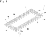
- Fig. 1 shows a thin resin sheet member 1 (hereinafter, simply referred to as sheet member 1) according to a first embodiment of the present invention.
- the sheet member 1 of the present embodiment is a fuel cell gasket.
- the sheet member 1 is manufactured by injection molding of a thermoplastic resin.
- the sheet member 1 has two opposing surfaces having an area sufficiently larger than the other surfaces, that is, a pair of main surfaces 1a and 1b.
- the interval between the main surfaces 1a and 1b, that is, a thickness THm of the sheet member 1 is constant or uniform.
- the sheet member 1 (gasket) is thinner than a gasket manufactured by conventional injection molding. That is, the thickness THm of the sheet member 1 is set to 40 ⁇ m or more and 450 ⁇ m or less.
- the thickness THm of the sheet member 1 is preferably set to 50 ⁇ m or more and 350 ⁇ m or less, and more preferably 100 ⁇ m or more and less than 200 ⁇ m.
- the thickness THm of the sheet member 1 is not necessarily uniform.
- the maximum thickness that is, the maximum value (maximum interval between main surfaces 1a and 1b) of the thickness THm is set to 40 ⁇ m or more and 450 ⁇ m or less, preferably 50 ⁇ m or more and 350 ⁇ m or less, and more preferably 100 ⁇ m or more and less than 200 ⁇ m.
- the overall shape of the sheet member 1 of the present embodiment is a flat rectangular frame shape and includes a pair of longer portions 2A and 2B extending in the longer direction of the sheet member 1 and a pair of shorter portions 3A and 3B extending in the shorter direction of the sheet member 1 and connecting end portions of the longer portions 2A and 2B, respectively.
- the sheet member 1 of the present embodiment includes an inner peripheral edge portion 4 and an outer peripheral edge portion 5 each having a rectangular shape when viewed from a direction facing the main surfaces 2a and 2b.
- a forming mold 100 for injection molding the sheet member 1 includes an upper mold 101 and a lower mold 102.
- a cavity 103 defined by the upper mold 101 and the lower mold 102 includes one product portion 104, a plurality (10) of gate/runner portions 105, and one land portion 106.
- the product portion 104 is a portion where the sheet member 1 is to be molded and has substantially the same size and shape as those of the sheet member 1.
- the product portion 104 has an inner peripheral edge portion 104a and an outer peripheral edge portion 104b corresponding to the inner peripheral edge portion 4 and the outer peripheral edge portion 5 of the sheet member 1, respectively. Both the inner peripheral edge portion 104a and the outer peripheral edge portion have a rectangular shape in plan view.
- a thickness THp of the product portion 104 is substantially the same as the thickness THm of the sheet member 1.
- the maximum value of the thickness THp of the product portion 104 is set to 40 ⁇ m or more and 450 ⁇ m or less, preferably 50 ⁇ m or more and 350 ⁇ m or less, and more preferably 100 ⁇ m or more and less than 200 ⁇ m.
- the gate/runner portions 105 are arranged inside the product portion 104 in plan view.
- Each gate/runner portion 105 fluidically communicates with a molding machine injection unit (not shown) via a spool mechanism 107 provided in the upper mold 101.
- a molten thermoplastic resin is supplied from the molding machine injection unit to the gate/runner portion 105.
- the spool mechanism 107 supplies the thermoplastic resin to the gate/runner portion 105 only when the upper mold 101 and the lower mold 102 are clamped. Therefore, a trace corresponding to the shape of an outlet hole of the spool mechanism 107 remains in a second non-product portion 109 described later.
- Each gate/runner portion 105 fluidically communicates with the land portion 106.
- the land portion 106 is arranged inside the product portion 104 in plan view.
- the land portion 106 is interposed between the gate/runner portions 105 and the product portion 104.
- the land portion 106 has a rectangular shape in plan view and communicates with the entire region of the inner peripheral edge portion of the product portion 104.
- the thickness THz of the land portion 106 is larger than the thickness THp of the product portion 104.
- the thickness THz of the land portion 106 is set to 1.3 times or more and 24 times or less, preferably 2.5 times or more and 10 times or less the thickness THp of the product portion 104.
- the thickness THz of the land portion 106 is set to be equal to or less than the thickness THgr of the gate/runner portion 105.
- the thickness TH of the land portion 106 is set to 0.12 times or more and 1.0 times or less the thickness THgr of the gate/runner portion 105.
- the thickness THp of the product portion 104, the thickness THz of the land portion 106, and the thickness THgr (average thickness) of the gate/runner portion 105 are set to satisfy the relationship of the following Formula (1). THp ⁇ THz ⁇ THgr
- the thickness THz of the land portion 106 satisfies the above conditions and is set to 300 ⁇ m or more and 1200 ⁇ m or less, preferably 500 ⁇ m or more and 1000 ⁇ m or less in terms of an average thickness.
- the thickness THz of the land portion 106 is constant, and the average thickness is set to 500 ⁇ m.
- the thickness THz of the land portion 106 is three times the thickness THp of the product portion 104.
- the molten thermoplastic resin supplied from the molding machine injection unit to the gate/runner portion 105 flows into the land portion 106, but the thermoplastic resin does not substantially flow into the product portion 104 until the land portion 106 is filled with the thermoplastic resin, that is, until the entire volume of the land portion 106 is occupied by the thermoplastic resin.
- the molten thermoplastic resin is further supplied from the gate/runner portion 105 to the land portion 106 in a state where the entire volume of the land portion 106 is occupied by the thermoplastic resin, the molten thermoplastic resin simultaneously flows from the land portion 106 into the product portion 104 as indicated by broken line arrows in Fig. 5 . More specifically, as indicated by broken line arrows in Fig. 5 , the molten thermoplastic resin flows in one direction from the inner peripheral edge portion 104a toward the outer peripheral edge portion 104b of the product portion 104.
- the land portion 106 functions as a portion for storing the molten thermoplastic resin in order to uniformly flow the required resin in one direction into the product portion 104.
- the thermoplastic resin needs to flow into the entire land portion 106 in preference to the inflow into the product portion 104.
- the inflow of the thermoplastic resin of such an aspect is realized.
- the temperature of the forming mold 100 is preferably maintained at 20°C or more and 80°C or less, and preferably 40°C or more and 80°C or less. In the present embodiment, the temperature of the forming mold 100 is maintained at 40°C or more and 50°C or less.
- a cooling hole may be provided in the forming mold 100 (upper mold 101, lower mold 102) to maintain an appropriate temperature.
- the thermoplastic resin preferably has a melt mass flow rate (measurement conditions: JIS K 7210 230°C, 2.16 kg) of 10 g/10 min or more and 300 g/10 min or less and a heat of fusion of 0 mj/mg or more and 150 mj/mg or less, preferably 50 mj/mg or more and 110 mj/mg or less.
- a melt mass flow rate (measurement conditions: JIS K 7210 230°C, 2.16 kg) of 10 g/10 min or more and 300 g/10 min or less and a heat of fusion of 0 mj/mg or more and 150 mj/mg or less, preferably 50 mj/mg or more and 110 mj/mg or less.
- thermoplastic resins that can be employed.
- the orientation of the thermoplastic resin is aligned in the flow direction of the thermoplastic resin as described above (broken line arrows in Fig. 5 ). With the orientation of the thermoplastic resin being aligned like this, the sheet member 1 having excellent dimensional stability is obtained as compared with a thin resin sheet member made of extruded thin resin film.
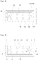
- Figs. 6 and 7 show the sheet member 1 taken out from the forming mold 100 after completion of injection molding.
- a first non-product portion 108 having a rectangular frame shape and corresponding to the land portion 106 is formed inside the sheet member 1, and a second non-product portion 109 corresponding to the gate/runner portion 105 is formed further inside the first non-product portion 108.
- the first non-product portion 108 has a thickness THn1 corresponding to the thickness THz of the land portion 106
- the second non-product portion 109 has a thickness THn2 corresponding to the thickness THgr of the gate/runner portion 105.
- a plurality of coherent pattern lines CL arranged at intervals in the direction in which the inner peripheral edge portion 4 and the outer peripheral edge portion 5 oppose each other appear in both the longer portions 2A and 2B and the shorter portions 3A and 3B.
- a pair in the coherent pattern lines CL adjacent to each other do not intersect.
- the sheet member 1 of the present embodiment having a region in which the regular coherent pattern lines CL appear as described above is not attributed to the manufacture by press working on an extruded thin resin film but attributed to the manufacture by injection molding as described above. That is, it can be said that the appearance of the regular coherent pattern lines CL as described above indirectly indicates that the orientation of the thermoplastic resin is aligned and the sheet member 1 manufactured by injection molding as described above has excellent dimensional stability as compared with a thin resin sheet member made of extruded thin resin film.
- the sheet member 1 (gasket) is manufactured by injection molding such that the orientation direction of the thermoplastic resin is aligned as described above, the sheet member 1 has excellent dimensional stability as compared with a gasket made of extruded thin resin film.
- the thickness THm of the sheet member 1 (gasket) is 40 ⁇ m or more and 450 ⁇ m or less, preferably 50 ⁇ m or more and 350 ⁇ m or less, and more preferably 100 ⁇ m or more and less than 200 ⁇ m, which is further thinned than a gasket manufactured by conventional injection molding. Therefore, using the sheet member 1 of the present embodiment as a gasket enables downsizing of a fuel cell.
- the sheet member 1 of the present embodiment has excellent dimensional stability because the orientation direction of the thermoplastic resin is aligned.
- the orientation direction of the thermoplastic resin is not necessarily aligned in the entire region of the sheet member 1.
- the entire main surfaces 1a and 1b are not necessarily the regions in which the plurality of coherent pattern lines CL are arranged at intervals in the direction in which the inner peripheral edge portion 4 and the outer peripheral edge portion 5 oppose each other as described above, and the adjacent coherent pattern lines CL do not intersect each other.
- a region is 50% or more, preferably 70% or more of the total area of the main surfaces 1a and 1b, the dimensional stability because of the alignment of the orientation direction of the thermoplastic resin can improve.
- Figs. 8 to 18 show modifications of the first embodiment. These embodiments can also be applied to second to eighth embodiments described later.
- a spool bush 110 in which a spool 110a is formed is attached to the upper mold 101. That is, the forming mold 100 in this modification is a so-called direct spool mold. In the present modification, an elongated conical trace corresponding to the spool 110a remains in the second non-product portion 109.
- the cavity 103 defined by the forming mold 100 includes the land portion 106 arranged outside the product portion 104 and a plurality of gate/runner portions 105 arranged outside the land portion 106.
- the molten thermoplastic resin flows in one direction from the outer peripheral edge portion 104a toward the inner peripheral edge portion 104b of the product portion 104 as indicated by broken line arrows in Fig. 9 .
- Figs. 9 As shown in Figs.
- the first non-product portion 108 corresponding to the land portion 106 is formed outside the product portion 104
- the second non-product portion 109 corresponding to the gate/runner portion 105 is formed outside the first non-product portion 108.
- the gate/runner portion 105 includes a portion opposing the spool mechanism 107 or the spool bush 110, that is, one gate portion 105a into which a molten thermoplastic resin flows, inside the land portion 106.
- the gate/runner portion 105 in the present embodiment includes a plurality of runner portions 105b branched from the gate portion 105a and connected to the land portion 106.
- an overflow portion 112 is provided in the cavity 103 in such a manner as to surround the entire region of the outer side of the product portion 106. Therefore, as shown in Figs. 15 and 16 , in a state of being taken out from the forming mold 100 after injection molding, a third non-product portion 113 is formed in such a manner as to surround the entire region of the outer side of the product portion 104. The third non-product portion 113 is removed from the sheet member 1 by means such as cutting similarly to the first and second non-product portions 108 and 109.
- a thickness THo of the overflow portion 112 is set to be the same as the thickness THp of the product portion 106.
- the thickness THz is constant in the portion on the gate/runner portion 105 side of the land portion 106, but the thickness THz gradually decreases toward the product portion 104 in the portion of the land portion 106 connected to the product portion 104.
- the thickness THz of the land portion 106 gradually decreases from the portion connected to the gate/runner portion 105 toward the portion connected to the product portion 104.
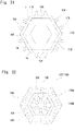
- Fig. 19 shows a sheet member 1 according to a second embodiment of the present invention.
- the sheet member 1 of the present embodiment has a hexagonal shape as its overall shape, and includes six straight side portions 11A, 11B, 11C, 11D, 11E, and 11F.
- the forming mold 100 is provided with the land portion 106 having a hexagonal shape outside the product portion 104 having a hexagonal shape in plan view.
- Two gate/runner portions 105 are provided outside each portion corresponding to the side portions 11A to 11F of the land portion 106.
- the molten thermoplastic resin supplied from the molding machine injection unit to the gate/runner portion 105 fills the land portion 106, and then simultaneously flows from the land portion 106 into the product portion 104 as indicated by broken line arrows in Fig. 20 . More specifically, as indicated by broken line arrows in Fig. 20 , the molten thermoplastic resin flows in one direction from the outer peripheral edge portion 104b toward the inner peripheral edge portion 104a of the product portion 104.
- Fig. 21 shows the sheet member 1 taken out from the forming mold 100 after completion of injection molding.
- the first non-product portion 108 having a hexagonal shape and corresponding to the land portion 106 is formed outside the sheet member 1, and the second non-product portion 109 corresponding to the gate/runner portion 105 is formed further outside the first non-product portion 108.
- a plurality of coherent pattern lines CL conceptually indicated by two-dot chain lines in Fig. 19 appear in the sheet member 1.
- a plurality of coherent pattern lines CL arranged at intervals in a direction in which the inner peripheral edge portion 4 and the outer peripheral edge portion 5 oppose each other appear.
- a pair in the coherent pattern lines CL adjacent to each other do not intersect.
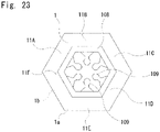
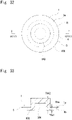
- Figs. 22 and 23 show a modification of the second embodiment.
- the cavity 103 defined by the forming mold 100 includes the land portion 106 arranged inside the product portion 104 and a plurality of gate/runner portions 105 arranged inside the land portion 106.
- the molten thermoplastic resin flows in one direction from the inner peripheral edge portion 104a toward the outer peripheral edge portion 104b of the product portion 104 as indicated by broken line arrows in Fig. 22 .
- Fig. 22 show a modification of the second embodiment.
- the cavity 103 defined by the forming mold 100 includes the land portion 106 arranged inside the product portion 104 and a plurality of gate/runner portions 105 arranged inside the land portion 106.
- the molten thermoplastic resin flows in one direction from the inner peripheral edge portion 104a toward the outer peripheral edge portion 104b of the product portion 104 as indicated by broken line arrows in Fig. 22 .
- Fig. 22 shows a modification of the second embodiment.
- the first non-product portion 108 corresponding to the land portion 106 is formed inside the product portion 104, and the second non-product portion 109 corresponding to the gate/runner portion 105 is formed inside the first non-product portion 108.
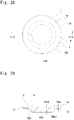
- Fig. 24 shows the sheet member 1 according to a third embodiment of the present invention.
- the sheet member 1 of the present embodiment has an annular shape.
- the sheet member 1 has a substantially perfect circular shape in plan view, but it may have an elliptical shape in plan view.
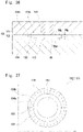
- the forming mold 100 is provided with the land portion 106 having an annular shape inside the product portion 104 having an annular shape in plan view.
- a single gate/runner portion 105 having a cylindrical shape is provided inside the land portion 106.
- the entire region of the inside of the land portion 106 communicates with the gate/runner portion 105.
- the molten thermoplastic resin supplied from the molding machine injection unit to the gate/runner portion 105 fills the land portion 106, and then simultaneously flows from the land portion 106 into the product portion 104 as indicated by broken line arrows in Fig. 27 .
- Figs. 28 and 29 show the sheet member 1 taken out from the forming mold 100 after completion of injection molding.
- the first non-product portion 108 having an annular shape and corresponding to the land portion 106 is formed outside the sheet member 1
- the second non-product portion 109 having a cylindrical shape and corresponding to the gate/runner portion 105 is formed further outside the first non-product portion 108.
- manufacturing of the sheet member 1 is completed.
- the sheet member 1 may be used as a finished product without removing the first non-product portion 108 and the second non-product portion 109.
- first non-product portion 108 and the second non-product portion 109 are not removed from the sheet member 1, these portions become thick portions having thicknesses THn 1 and THn2 larger than the interval (thickness THm) between the main surfaces 1a and 1b.
- Such thick portions are preferably 50% or less of the total area of the sheet member 1 in view of ensuring dimensional stability by aligning the orientation of the thermoplastic resin in the portion other than the thick portions of the sheet member 1.
- the sheet member 1 from which the first non-product portion 108 and the second non-product portion 109 are not removed can be used as a finished product in a modification of the present embodiment described later, as well as other embodiments other than the present embodiment and modifications thereof.
- the second non-product portion 109 is removed from the sheet member 1, but the sheet member 1 may be used as a finished product without removing the first non-product portion 108.
- a plurality of coherent pattern lines CL appear in the sheet member 1 as conceptually indicated by two-dot chain lines in Fig. 24 .
- a plurality of coherent pattern lines CL arranged at intervals in a direction in which the inner peripheral edge portion 4 and the outer peripheral edge portion 5 oppose each other appear.
- a pair in the coherent pattern lines CL adjacent to each other do not intersect.
- Figs. 30 to 33 show modifications of the present embodiment.
- the gate/runner portion 105 protrudes upward from the product portion 104 and the land portion 106 in the drawings.
- the lower mold 102 includes a cylindrical portion 102a protruding upward in the drawings in a portion defining the gate/runner portion 105. Therefore, as shown in Figs. 32 and 33 , the second non-product portion 109 in this modification protrudes upward from the sheet member 1 and the first non-product portion 108 in the drawings and has a shape in which a cylindrical recess is formed at the lower end.
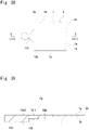
- Fig. 34 shows the sheet member 1 according to a fourth embodiment of the present invention.
- the sheet member 1 of the present embodiment has a flat rectangular shape.
- the outer peripheral edge portion 5 of the sheet member 1 includes a pair of straight edge portions 5a and 5b opposing each other and a pair of straight edge portions 5c and 5d opposing each other and connecting end portions of the straight edge portions 5a and 5b.
- the forming mold 100 is provided with the land portion 106 having an elongated rectangular shape of a constant width at a portion corresponding to the straight edge portion 5a of the product portion 104.
- a single gate/runner portion 105 is provided on the opposite side of the land portion 106 from the product portion 104.
- the molten thermoplastic resin supplied from the molding machine injection unit to the gate/runner portion 105 fills the land portion 106, and then simultaneously flows from the land portion 106 into the product portion 104 as indicated by broken line arrows in Fig. 37 . More specifically, as indicated by the broken line arrows in Fig. 37 , the molten thermoplastic resin flows in one direction from the portion corresponding to the straight edge portion 5a toward the portion corresponding to the straight edge portion 5b of the outer peripheral edge portion 104b of the product portion 104.
- Figs. 38 and 39 show the sheet member 1 taken out from the forming mold 100 after completion of injection molding.
- the first non-product portion 108 having an elongated rectangular shape and corresponding to the land portion 106 is formed on the straight edge portion 5a side of the sheet member 1, and the second non-product portion 109 corresponding to the gate/runner portion 105 is formed on the opposite side of the first non-product portion 108 from the sheet member 1.
- a plurality of coherent pattern lines CL conceptually indicated by two-dot chain lines in Fig. 34 appear in the sheet member 1. Specifically, a plurality of coherent pattern lines CL arranged at intervals in a direction in which the straight edge portion 5a and the straight edge portion 5b oppose each other appear. A pair in the coherent pattern lines CL adjacent to each other do not intersect.
- Figs. 40 and 41 show a modification of the fourth embodiment.
- a plurality of through holes 1c are formed in the sheet member 1 of the modification shown in Fig. 40 .
- a through hole as shown in Fig. 40 and a notch as shown in Fig. 41 may be provided in the sheet member 1 according to an embodiment other than the fourth embodiment.
- Fig. 42 shows the sheet member 1 according to a fifth embodiment of the present invention.
- the sheet member 1 of the present embodiment has a flat rectangular shape as in the fourth embodiment ( Fig. 34 ) but is longer than the sheet member 1 of the fourth embodiment. That is, the straight edge portions 5a and 5b which are parts of the outer peripheral edge portion 5 are sufficiently longer than the straight edge portions 5c and 5d which are also parts of the outer peripheral edge portion 5.
- the forming mold 100 is provided with the land portion 106 having an elongated rectangular shape of a constant width at a portion corresponding to the straight edge portion 5a of the product portion 104.
- a plurality of gate/runner portions 105 are provided on the opposite side of the land portion 106 from the product portion 104.
- the molten thermoplastic resin supplied from the molding machine injection unit to the gate/runner portion 105 fills the land portion 106, and then simultaneously flows from the land portion 106 into the product portion 104 as indicated by the broken line arrows. More specifically, the molten thermoplastic resin flows in one direction from the portion corresponding to the straight edge portion 5c toward the portion corresponding to the straight edge portion 5b of the outer peripheral edge portion 104b of the product portion 104.
- Fig. 44 shows the sheet member 1 taken out from the forming mold 100 after completion of injection molding.
- the first non-product portion 108 having an elongated rectangular shape and corresponding to the land portion 106 is formed on the straight edge portion 5a side of the sheet member 1, and the second non-product portion 109 corresponding to the gate/runner portion 105 is formed on the opposite side of the first non-product portion 108 from the sheet member 1.
- Fig. 45 shows the sheet member 1 according to a modification of the present embodiment.
- a semicircular notch 1e and a rectangular notch 1f are formed in the straight edge portion 5c of the sheet member 1.
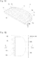
- Fig. 46 shows the sheet member 1 according to a sixth embodiment of the present invention.
- the sheet member 1 of the present embodiment has a semicircular arc shape.
- the outer peripheral edge portion 5 of the sheet member 1 includes a pair of arcuate edge portions 5e and 5f opposing each other and a pair of straight edge portions 5g and 5h connecting end portions of the arcuate edge portions 5e and 5f.
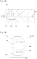
- the forming mold 100 is provided with the land portion 106 having a semicircular arc shape of a constant width in a portion corresponding to the arcuate edge portion 5e of the product portion 104.
- a single gate/runner portion 105 having a semi-cylindrical shape is provided on the opposite side of the land portion 106 from the product portion 104.
- the molten thermoplastic resin supplied from the molding machine injection unit to the gate/runner portion 105 fills the land portion 106, then simultaneously flows from the land portion 106 into the product portion 104, and then flows in one direction from the portion corresponding to the arcuate edge portion 5e toward the portion corresponding to the arcuate edge portion 5f of the outer peripheral edge portion 104b of the product portion 104.
- Figs. 49 and 50 show the sheet member 1 taken out from the forming mold 100 after completion of injection molding.
- the first non-product portion 108 having an annular shape and corresponding to the land portion 106 is formed on the arcuate edge portion 5e side of the sheet member 1
- the second non-product portion 109 having a semi-cylindrical shape and corresponding to the gate/runner portion 105 is formed on the opposite side of the first non-product portion 108 from the sheet member 1.
- a plurality of coherent pattern lines CL conceptually indicated by two-dot chain lines in Fig. 46 appear in the sheet member 1. Specifically, a plurality of coherent pattern lines CL arranged at intervals in a direction in which the straight edge portion 5a and the straight edge portion 5b oppose each other appear. A pair in the coherent pattern lines CL adjacent to each other do not intersect.
- Fig. 51 shows the sheet member 1 according to a seventh embodiment of the present invention.
- the outer peripheral edge portion 5 of the sheet member 1 of the present embodiment includes four edge portions similarly to the fourth and fifth embodiments. Specifically, the outer peripheral edge portion 5 of the sheet member 1 includes a pair of relatively short straight edge portions 5i and 5j opposing each other, a relatively long straight edge portion 5k connecting the straight edge portions 5i and 5j, and a curved edge portion 5m opposing the straight edge portion 5k.
- the forming mold 100 is provided with the land portion 106 having an elongated rectangular shape at a portion corresponding to the straight edge portion 5k of the product portion 104.
- a plurality of gate/runner portions 105 are provided on the opposite side of the land portion 106 from the product portion 104.
- the molten thermoplastic resin supplied from the molding machine injection unit to the gate/runner portion 105 fills the land portion 106, and then simultaneously flows from the land portion 106 into the product portion 104 as indicated by broken line arrows in Fig. 54 . More specifically, the molten thermoplastic resin flows in one direction from the portion corresponding to the straight edge portion 5k toward the portion corresponding to the curved edge portion 5m of the outer peripheral edge portion 104b of the product portion 104.
- Fig. 55 shows the sheet member 1 taken out from the forming mold 100 after completion of injection molding.
- the first non-product portion 108 having an elongated rectangular shape and corresponding to the land portion 106 is formed on the straight edge portion 5k side of the sheet member 1, and the second non-product portion 109 corresponding to the gate/runner portion 105 is formed on the opposite side of the first non-product portion 108 from the sheet member 1.
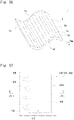
- Fig. 56 shows the sheet member 1 according to an eighth embodiment of the present invention.
- the sheet member 1 of the present embodiment has a rectangular shape as in the fourth and fifth embodiments ( Figs. 34 and 42 ) when viewed from the opposing direction of the main surfaces 1a and 1b, and the outer peripheral edge portion 5 includes a pair of straight edge portions 5a and 5b and another pair of straight edge portions 5c and 5d connecting the pair of straight edge portions 5a and 5b. While the sheet member 1 of the fourth and fifth embodiments ( Figs. 34 and 42 ) is flat, the sheet member 1 of the present embodiment is curved and has a curved surface shape. In the present embodiment, the sheet member 1 has a curve only in a direction in which the straight edge portions 5a and 5b oppose each other. However, the sheet member 1 may have a three-dimensional curved surface shape.
- the forming mold 100 is provided with the land portion 106 having an elongated rectangular shape of a constant width at a portion corresponding to the straight edge portion 5a of the product portion 104.
- a plurality of gate/runner portions 105 are provided on the opposite side of the land portion 106 from the product portion 104.
- the molten thermoplastic resin supplied from the molding machine injection unit to the gate/runner portion 105 fills the land portion 106, and then simultaneously flows from the land portion 106 into the product portion 104 as indicated by broken line arrows in Fig. 59 . More specifically, as indicated by broken line arrows in Fig. 59 , the molten thermoplastic resin flows in one direction from the portion corresponding to the straight edge portion 5a toward the portion corresponding to the straight edge portion 5b of the outer peripheral edge portion 104b of the product portion 104.
- Fig. 60 shows the sheet member 1 taken out from the forming mold 100 after completion of injection molding.
- the first non-product portion 108 having an elongated rectangular shape and corresponding to the land portion 106 is formed on the straight edge portion 5a side of the sheet member 1, and the second non-product portion 109 corresponding to the gate/runner portion 105 is formed on the opposite side of the first non-product portion 108 from the sheet member 1.
- a plurality of coherent pattern lines CL conceptually indicated by two-dot chain lines in Fig. 56 appear in the sheet member 1. Specifically, a plurality of coherent pattern lines CL arranged at intervals in a direction in which the straight edge portion 5a and the straight edge portion 5b oppose each other appear. A pair in the coherent pattern lines CL adjacent to each other do not intersect.
- samples S1 and S2 are cut out from the longer portion 2A of the gasket 1 according to an embodiment (Example).
- samples S3 to S6 are cut out from a thin resin film 200 that has been extruded (Comparative Example).
- the samples S3 and S4 are elongated in the flow direction (MD direction) of the resin in the extrusion molding, and the samples S5 and S6 are elongated in the direction (TD direction) orthogonal to the MD direction.
- the shrinkage ratio is less than 0.6% in both the longer direction and the shorter direction, whereas in the samples S3 and S4 of Comparative Example, the shrinkage ratio is more than 0.8% in both the MD direction and the TD direction.
- the test results indicate that the gasket 1 of the present embodiment manufactured by injection molding has excellent dimensional stability as compared with a gasket made of extruded thin resin film.
- the present invention can also be applied to other thin resin sheet members such as gaskets and separators for other batteries such as nickel hydrogen batteries in addition to a fuel cell gasket.
- 1 Thin resin sheet member (sheet member), 1a; 1b: Main surface, 1c: Through hole, 1d; 1e; 1f: Notch, 2A; 2B: Longer portion, 3A; 3B: Shorter portion, 4: Inner peripheral edge portion, 5: Outer peripheral edge portion, 5a, 5b, 5c, 5d: Straight edge portion, 5e, 5f: Arcuate edge portion, 5g; 5h: Straight edge portion, 5i; 5j; 5k: Straight edge portion, 5m: Curved edge portion, 11A; 11B; 11C; 11D; 11E; 11F: Side portion, 100: Forming mold, 101: Upper mold, 102: Lower mold, 102a: Cylindrical portion, 103: Cavity, 104: Product portion, 104a: Inner peripheral edge portion, 104b: Outer peripheral edge portion, 105: Gate/runner portion, 105a: Gate portion, 105b: Runner portion, 106: Land portion, 107: Spool, 108: First non-product portion
Landscapes
- Engineering & Computer Science (AREA)
- Manufacturing & Machinery (AREA)
- Mechanical Engineering (AREA)
- Sustainable Development (AREA)
- Sustainable Energy (AREA)
- Chemical & Material Sciences (AREA)
- Chemical Kinetics & Catalysis (AREA)
- Electrochemistry (AREA)
- General Chemical & Material Sciences (AREA)
- Life Sciences & Earth Sciences (AREA)
- General Engineering & Computer Science (AREA)
- Moulds For Moulding Plastics Or The Like (AREA)
- Fuel Cell (AREA)
- Injection Moulding Of Plastics Or The Like (AREA)
Abstract
Description
- The present invention relates to a thin resin sheet member and a method for manufacturing the same.
- As a method for manufacturing a fuel cell gasket which is an example of a thin resin sheet member, it is known that an extruded thin resin film is formed into a desired shape by press working.
Patent Document 1 discloses a manufacture of a fuel cell gasket by injection molding. - Patent Document 1:
JP 2016-207445 A - A fuel cell gasket manufactured by press working on a thin resin film obtained by extrusion molding is inferior in dimensional stability.
- A fuel cell gasket preferably has a small thickness from the viewpoint of downsizing a fuel cell. However, the fuel cell gasket manufactured by injection molding disclosed in
Patent Document 1 has a minimum thickness of 0.2 mm, and there is room for further reducing the thickness. - An object of the present invention is to provide a thin resin sheet member made of thin resin having good dimensional stability.
- A first aspect of the present invention is a thin resin sheet member including a pair of main surfaces opposing each other, wherein the thin resin sheet member has a maximum thickness of 40 µm or more and 450 µm or less, the maximum thickness being a maximum interval between the pair of main surfaces, and the thin resin sheet member has a region in which a plurality of coherent pattern lines appear when viewed from a direction facing the pair of main surfaces, the plurality of coherent pattern lines being arranged at intervals in a direction in which one edge portion and another edge portion opposing the one edge portion oppose each other, and a pair in the plurality of coherent pattern lines adjacent to each other do not intersect.
- Specifically, the region is 50% or more of a total area of the pair of main surfaces.
- The thin resin sheet member having a region in which the regular coherent pattern lines appear as described above is not attributed to a manufacture by press working on an extruded thin resin film but attributed to a manufacture by injection molding of an aspect as described later, that is, by the injection molding according to the manufacturing method of the second aspect. The thin resin sheet member of the present invention manufactured by such injection molding has excellent dimensional stability as compared with a thin resin sheet member made of extruded thin resin film.
- The thin resin sheet member according to the present invention has a maximum thickness of 40 µm or more and 450 µm or less, that is, the sheet member is further thinned than a thin resin sheet member manufactured by conventional injection molding. Therefore, the thin resin sheet member according to the present invention can contribute to downsizing of a fuel cell when the sheet member is used as a fuel cell gasket.
- A second aspect of the present invention is a method for manufacturing a thin resin sheet member, the method including preparing a forming mold defining a cavity including a product portion in which a thin resin sheet member is molded, a gate/runner portion communicating with a molding machine injection unit, and a land portion communicating with the gate/runner portion and communicating with one edge portion of the product portion, wherein the land portion has a thickness larger than a thickness of the product portion, and supplying a molten resin from the molding machine injection unit to the gate/runner portion, wherein after the molten resin fills the land portion, the molten resin flows from the one edge portion into the product portion and flows toward another edge portion opposing the one edge portion of the product portion.
- After the molten resin fills the land portion, the molten resin flows from one edge portion of the product portion into the product portion, and flows toward another edge portion opposing the one edge portion of the product portion. As a result, the resin flows in one direction from one edge portion to the other edge portion in the product portion, and the orientation of the resin is aligned in this flow direction. With the orientation of the resin being aligned like this, a thin resin sheet member having excellent dimensional stability is obtained as compared with a thin resin sheet member made of extruded thin resin film.
- In the thin resin sheet member obtained by the manufacturing method of the second aspect of the present invention, the orientation of the resin is aligned in one direction as described above. Therefore, the thin resin sheet member has a region in which a plurality of coherent pattern lines arranged at intervals in the direction in which the resin is oriented, that is, in the direction in which one edge portion of the product portion and another edge portion opposing the one edge portion oppose each other (direction in which one edge portion of the thin resin sheet member and another edge portion opposing the one edge portion oppose each other) appear, and a pair in the coherent pattern lines adjacent to each other do not intersect.
- The thickness of the land portion may be set to 1.3 times or more and 24 times or less the thickness of the product portion.
- The average thickness of the land portion may be set to 300 µm or more and 1200 µm or less.
- The land portion may communicate with an entire region of an inner peripheral edge portion of the product portion, and after the molten resin fills the land portion, the molten resin may flow from the inner peripheral edge portion into the product portion and flow toward an outer peripheral edge portion of the product portion.
- The land portion may communicate with an entire region of an outer peripheral edge portion of the product portion, and after the molten resin fills the land portion, the molten resin may flow from the outer peripheral edge portion into the product portion and flow toward an inner peripheral edge portion of the product portion.
- The product portion may have an outer peripheral edge portion including a plurality of edge portions, the land portion may communicate with one edge portion constituting a part of the outer peripheral edge portion of the product portion, and after the molten resin fills the land portion, the molten resin may flow from the one edge portion toward another edge portion opposing the one edge portion constituting a part of the outer peripheral edge portion.
- The resin may be a thermoplastic resin having a melt mass flow rate of 10 g/10 min or more and 300 g/10 min or less and a heat of fusion of 0 mj/mg or more and 150 mj/mg or less.
- According to the present invention, a thin resin sheet member having good dimensional stability that is thinned to have a maximum thickness of 40 µm or more and 450 µm or less is obtained.
-
-
Fig. 1 is a schematic perspective view of a sheet member (fuel cell gasket) according to a first embodiment of the present invention; -
Fig. 2 is a photograph of a part ofFig. 1 ; -
Fig. 3 is a schematic plan view of a forming mold for manufacturing the sheet member according to the first embodiment; -
Fig. 4 is a cross-sectional view taken along the line IV-IV inFig. 3 ; -
Fig. 5 is a schematic plan view of a lower mold for explaining an orientation of a resin in injection molding; -
Fig. 6 is a schematic plan view of a sheet member when taken out from a forming mold; -
Fig. 7 is a cross-sectional view taken along the line VII-VII inFig. 6 ; -
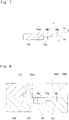
Fig. 8 is a cross-sectional view similar toFig. 4 , of another example of a forming mold that can be used for manufacturing the sheet member of the first embodiment; -
Fig. 9 is a schematic plan view similar toFig. 5 , of another forming mold (lower mold) that can be used for manufacturing the sheet member of the first embodiment; -
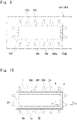
Fig. 10 is a schematic plan view of a sheet member when taken out from the forming mold ofFig. 9 ; -
Fig. 11 is a cross-sectional view taken along the line XI-XI inFig. 10 ; -
Fig. 12 is a schematic plan view similar toFig. 5 , of another forming mold (lower mold) that can be used for manufacturing the sheet member of the first embodiment; -
Fig. 13 is a schematic plan view of the sheet member when taken out from the forming mold ofFig. 12 ; -
Fig. 14 is a cross-sectional view similar toFig. 4 , of another example of a forming mold that can be used for manufacturing the sheet member of the first embodiment; -
Fig. 15 is a schematic plan view of the sheet member when taken out from the forming mold ofFig. 14 ; -
Fig. 16 is a cross-sectional view taken along the line XVI-XVI inFig. 14 ; -
Fig. 17 is a cross-sectional view similar toFig. 14 showing an alternative of a land portion; -
Fig. 18 is a cross-sectional view similar toFig. 14 showing an alternative of a land portion; -
Fig. 19 is a schematic perspective view of a sheet member according to a second embodiment of the present invention; -
Fig. 20 is a schematic plan view similar toFig. 5 , of a forming mold (lower mold) that can be used for manufacturing the sheet member of the second embodiment; -
Fig. 21 is a schematic plan view of the sheet member when taken out from the forming mold ofFig. 20 ; -
Fig. 22 is a schematic plan view similar toFig. 5 , of another forming mold (lower mold) that can be used for manufacturing the sheet member of the second embodiment; -
Fig. 23 is a schematic plan view of the sheet member when taken out from the forming mold ofFig. 22 ; -
Fig. 24 is a schematic perspective view of a sheet member according to a third embodiment of the present invention; -
Fig. 25 is a schematic plan view of a forming mold for manufacturing the sheet member according to the third embodiment; -
Fig. 26 is a cross-sectional view taken along the line XXVI-XXVI inFig. 25 ; -
Fig. 27 is a schematic plan view similar toFig. 5 , of a forming mold (lower mold) that can be used for manufacturing the sheet member of the third embodiment; -
Fig. 28 is a schematic plan view of the sheet member when taken out from the forming mold ofFig. 27 ; -
Fig. 29 is a cross-sectional view taken along the line XXIX-XXIX inFig. 28 ; -
Fig. 30 is a schematic plan view of another forming mold for manufacturing the sheet member according to the third embodiment; -
Fig. 31 is a cross-sectional view taken along the line XXXI-XXXI inFig. 30 ; -
Fig. 32 is a schematic plan view of the sheet member when taken out from the forming mold ofFig. 31 ; -
Fig. 33 is a cross-sectional view taken along the line XXXIII-XXXIII inFig. 32 ; -
Fig. 34 is a schematic perspective view of a sheet member according to a fourth embodiment of the present invention; -
Fig. 35 is a schematic plan view of a forming mold for manufacturing the sheet member according to the fourth embodiment; -
Fig. 36 is a cross-sectional view taken along the line XXXVI-XXXVI inFig. 35 ; -
Fig. 37 is a schematic plan view similar toFig. 5 , of a forming mold (lower mold) that can be used for manufacturing the sheet member of the fourth embodiment; -
Fig. 38 is a schematic plan view of the sheet member when taken out from the forming mold ofFig. 37 ; -
Fig. 39 is a cross-sectional view taken along the line XXXIX-XXXIX inFig. 38 ; -
Fig. 40 is a schematic plan view of a sheet member according to a modification of the fourth embodiment; -
Fig. 41 is a schematic plan view of a sheet member according to another modification of the fourth embodiment; -
Fig. 42 is a schematic perspective view of a sheet member according to a fifth embodiment of the present invention; -
Fig. 43 is a schematic plan view similar toFig. 5 , of a forming mold (lower mold) that can be used for manufacturing the sheet member of the fifth embodiment; -
Fig. 44 is a schematic plan view of the sheet member when taken out from the forming mold ofFig. 43 ; -
Fig. 45 is a schematic perspective view of a sheet member according to a modification of the fifth embodiment; -
Fig. 46 is a schematic perspective view of a sheet member according to a sixth embodiment of the present invention; -
Fig. 47 is a schematic plan view of a forming mold for manufacturing a sheet member according to a sixth embodiment; -
Fig. 48 is a cross-sectional view taken along the line XXXXVIII-XXXXVIII inFig. 47 ; -
Fig. 49 is a schematic plan view of the sheet member when taken out from the forming mold ofFig. 48 ; -
Fig. 50 is a cross-sectional view taken along the line L-L inFig. 49 ; -
Fig. 51 is a schematic perspective view of a sheet member according to a seventh embodiment of the present invention; -
Fig. 52 is a schematic plan view of a forming mold for manufacturing the sheet member according to the seventh embodiment; -
Fig. 53 is a cross-sectional view taken along the line LIII-LIII inFig. 42 ; -
Fig. 54 is a schematic plan view similar toFig. 5 , of a forming mold (lower mold) that can be used for manufacturing the sheet member of the seventh embodiment; -
Fig. 55 is a schematic plan view of the sheet member when taken out from the forming mold ofFig. 49 ; -
Fig. 56 is a schematic perspective view of a sheet member according to an eighth embodiment of the present invention; -
Fig. 57 is a schematic plan view of a forming mold for manufacturing the sheet member according to the eighth embodiment; -
Fig. 58 is a cross-sectional view taken along the line LVII-LVII inFig. 57 ; -
Fig. 59 is a schematic plan view similar toFig. 5 , of a forming mold (lower mold) that can be used for manufacturing the sheet member of the eighth embodiment; -
Fig. 60 is a schematic plan view of the sheet member when taken out from the forming mold ofFig. 59 ; -
Fig. 61 is a schematic plan view of a gasket used in an evaluation test; -
Fig. 62 is a schematic plan view of a comparative example used in an evaluation test. - Hereinafter, embodiments of the present invention will be described with reference to the accompanying drawings.
-
Fig. 1 shows a thin resin sheet member 1 (hereinafter, simply referred to as sheet member 1) according to a first embodiment of the present invention. Thesheet member 1 of the present embodiment is a fuel cell gasket. - As described later, the
sheet member 1 is manufactured by injection molding of a thermoplastic resin. - The
sheet member 1 has two opposing surfaces having an area sufficiently larger than the other surfaces, that is, a pair ofmain surfaces main surfaces sheet member 1 is constant or uniform. The sheet member 1 (gasket) is thinner than a gasket manufactured by conventional injection molding. That is, the thickness THm of thesheet member 1 is set to 40 µm or more and 450 µm or less. The thickness THm of thesheet member 1 is preferably set to 50 µm or more and 350 µm or less, and more preferably 100 µm or more and less than 200 µm. The thickness THm of thesheet member 1 is not necessarily uniform. That is, different portions of thesheet member 1 may have different thicknesses THm. When the thickness THm of thesheet member 1 is not uniform, the maximum thickness, that is, the maximum value (maximum interval betweenmain surfaces - The overall shape of the
sheet member 1 of the present embodiment is a flat rectangular frame shape and includes a pair oflonger portions sheet member 1 and a pair ofshorter portions sheet member 1 and connecting end portions of thelonger portions sheet member 1 of the present embodiment includes an innerperipheral edge portion 4 and an outerperipheral edge portion 5 each having a rectangular shape when viewed from a direction facing the main surfaces 2a and 2b. - Next, a method for manufacturing the
sheet member 1 of the present embodiment (injection molding method) will be described. - In
Figs. 3 to 5 , in the present embodiment, a formingmold 100 for injection molding thesheet member 1 includes anupper mold 101 and alower mold 102. In the present embodiment, acavity 103 defined by theupper mold 101 and thelower mold 102 includes oneproduct portion 104, a plurality (10) of gate/runner portions 105, and oneland portion 106. - The
product portion 104 is a portion where thesheet member 1 is to be molded and has substantially the same size and shape as those of thesheet member 1. In particular, theproduct portion 104 has an innerperipheral edge portion 104a and an outerperipheral edge portion 104b corresponding to the innerperipheral edge portion 4 and the outerperipheral edge portion 5 of thesheet member 1, respectively. Both the innerperipheral edge portion 104a and the outer peripheral edge portion have a rectangular shape in plan view. A thickness THp of theproduct portion 104 is substantially the same as the thickness THm of thesheet member 1. That is, the maximum value of the thickness THp of theproduct portion 104 is set to 40 µm or more and 450 µm or less, preferably 50 µm or more and 350 µm or less, and more preferably 100 µm or more and less than 200 µm. - In the present embodiment, the gate/
runner portions 105 are arranged inside theproduct portion 104 in plan view. - Each gate/
runner portion 105 fluidically communicates with a molding machine injection unit (not shown) via aspool mechanism 107 provided in theupper mold 101. A molten thermoplastic resin is supplied from the molding machine injection unit to the gate/runner portion 105. Thespool mechanism 107 supplies the thermoplastic resin to the gate/runner portion 105 only when theupper mold 101 and thelower mold 102 are clamped. Therefore, a trace corresponding to the shape of an outlet hole of thespool mechanism 107 remains in a secondnon-product portion 109 described later. - Each gate/
runner portion 105 fluidically communicates with theland portion 106. - In the present embodiment, the
land portion 106 is arranged inside theproduct portion 104 in plan view. Theland portion 106 is interposed between the gate/runner portions 105 and theproduct portion 104. Theland portion 106 has a rectangular shape in plan view and communicates with the entire region of the inner peripheral edge portion of theproduct portion 104. - The thickness THz of the
land portion 106 is larger than the thickness THp of theproduct portion 104. For example, the thickness THz of theland portion 106 is set to 1.3 times or more and 24 times or less, preferably 2.5 times or more and 10 times or less the thickness THp of theproduct portion 104. The thickness THz of theland portion 106 is set to be equal to or less than the thickness THgr of the gate/runner portion 105. For example, the thickness TH of theland portion 106 is set to 0.12 times or more and 1.0 times or less the thickness THgr of the gate/runner portion 105. The thickness THp of theproduct portion 104, the thickness THz of theland portion 106, and the thickness THgr (average thickness) of the gate/runner portion 105 are set to satisfy the relationship of the following Formula (1).

- The thickness THz of the
land portion 106 satisfies the above conditions and is set to 300 µm or more and 1200 µm or less, preferably 500 µm or more and 1000 µm or less in terms of an average thickness. In the present embodiment, the thickness THz of theland portion 106 is constant, and the average thickness is set to 500 µm. In the present embodiment, the thickness THz of theland portion 106 is three times the thickness THp of theproduct portion 104. - The molten thermoplastic resin supplied from the molding machine injection unit to the gate/
runner portion 105 flows into theland portion 106, but the thermoplastic resin does not substantially flow into theproduct portion 104 until theland portion 106 is filled with the thermoplastic resin, that is, until the entire volume of theland portion 106 is occupied by the thermoplastic resin. When the molten thermoplastic resin is further supplied from the gate/runner portion 105 to theland portion 106 in a state where the entire volume of theland portion 106 is occupied by the thermoplastic resin, the molten thermoplastic resin simultaneously flows from theland portion 106 into theproduct portion 104 as indicated by broken line arrows inFig. 5 . More specifically, as indicated by broken line arrows inFig. 5 , the molten thermoplastic resin flows in one direction from the innerperipheral edge portion 104a toward the outerperipheral edge portion 104b of theproduct portion 104. - The
land portion 106 functions as a portion for storing the molten thermoplastic resin in order to uniformly flow the required resin in one direction into theproduct portion 104. The thermoplastic resin needs to flow into theentire land portion 106 in preference to the inflow into theproduct portion 104. By setting the thickness THz of theland portion 106 to be thicker than the thickness THp of theproduct portion 104 as described above, the inflow of the thermoplastic resin of such an aspect is realized. When the inflow of the thermoplastic resin into theland portion 106 is completed, the internal pressure of the formingmold 100 increases, and the thermoplastic resin can flow from theland portion 106 into theproduct portion 104 having a smaller thickness. To realize such a uniform molten resin inflow state, the temperature of the formingmold 100 is preferably maintained at 20°C or more and 80°C or less, and preferably 40°C or more and 80°C or less. In the present embodiment, the temperature of the formingmold 100 is maintained at 40°C or more and 50°C or less. A cooling hole may be provided in the forming mold 100 (upper mold 101, lower mold 102) to maintain an appropriate temperature. - To realize the inflow state as described above, the thermoplastic resin preferably has a melt mass flow rate (measurement conditions: JIS K 7210 230°C, 2.16 kg) of 10 g/10 min or more and 300 g/10 min or less and a heat of fusion of 0 mj/mg or more and 150 mj/mg or less, preferably 50 mj/mg or more and 110 mj/mg or less.
- Table 1 below shows examples of thermoplastic resins that can be employed.
[Table 1] Thermoplastic resin Melting temperature (°C) Mold temperature (°C) Polypropylene (PP) 140-220 20-80 Polyethylene (PE) 140-200 20-70 Polybutylene terephthalate (PBT) 250 80 Polyethylene terephthalate (PET) 250-290 90-120 Polycarbonate (PC) 270-370 50-130 Polyamide (PA) 240-300 50-140 Polyacetal (POM) 180-240 60-140 Polyketone (POK) 240-250 60-80 Polysulfone (PSU) 360-390 138-163 Polyphenyl sulfone (PPSU) 350-380 105-160 Polyether sulfone (PES) 345-385 138-160 Polyphenylene sulfide (PPS) 300-350 135-180 Polyetherimide (PEI) 355-390 130-160 Polyetheretherketone (PEEK) 365-380 175-205 Modified polyphenyleneether (m-PPE) 250-300 50-110 Ethylene-vinyl acetate copolymer (EVA resin) 130-190 20-55 Cyclic olefin copolymer (COC) 260-280 80-90 - The orientation of the thermoplastic resin is aligned in the flow direction of the thermoplastic resin as described above (broken line arrows in
Fig. 5 ). With the orientation of the thermoplastic resin being aligned like this, thesheet member 1 having excellent dimensional stability is obtained as compared with a thin resin sheet member made of extruded thin resin film. -
Figs. 6 and7 show thesheet member 1 taken out from the formingmold 100 after completion of injection molding. A firstnon-product portion 108 having a rectangular frame shape and corresponding to theland portion 106 is formed inside thesheet member 1, and a secondnon-product portion 109 corresponding to the gate/runner portion 105 is formed further inside the firstnon-product portion 108. The firstnon-product portion 108 has a thickness THn1 corresponding to the thickness THz of theland portion 106, and the secondnon-product portion 109 has a thickness THn2 corresponding to the thickness THgr of the gate/runner portion 105. By removing the firstnon-product portion 108 and the secondnon-product portion 109 by means such as cutting, the manufacturing of thesheet member 1 is completed. - As described above, with the orientation of the thermoplastic resin being aligned in the flow direction of the thermoplastic resin (broken line arrows in
Fig. 5 ) in theproduct portion 104 of thecavity 103, regular coherent pattern lines appear in thesheet member 1. This coherent pattern lines can be observed by irradiating thesheet member 1 with illumination light. Specifically, in thesheet member 1, a plurality of coherent pattern lines CL conceptually indicated by two-dot chain lines inFig. 1 appear corresponding to the flow direction (orientation direction of the thermoplastic resin) of the thermoplastic resin indicated by broken line arrows inFig. 5 .Fig. 2 is a photograph of a part ofFig. 1 , in which the coherent pattern lines CL appear. In the present embodiment, when thesheet member 1 is viewed from the direction facing the main surfaces 2a and 2b, a plurality of coherent pattern lines CL arranged at intervals in the direction in which the innerperipheral edge portion 4 and the outerperipheral edge portion 5 oppose each other appear in both thelonger portions shorter portions - The
sheet member 1 of the present embodiment having a region in which the regular coherent pattern lines CL appear as described above is not attributed to the manufacture by press working on an extruded thin resin film but attributed to the manufacture by injection molding as described above. That is, it can be said that the appearance of the regular coherent pattern lines CL as described above indirectly indicates that the orientation of the thermoplastic resin is aligned and thesheet member 1 manufactured by injection molding as described above has excellent dimensional stability as compared with a thin resin sheet member made of extruded thin resin film. - Because the sheet member 1 (gasket) is manufactured by injection molding such that the orientation direction of the thermoplastic resin is aligned as described above, the
sheet member 1 has excellent dimensional stability as compared with a gasket made of extruded thin resin film. The thickness THm of the sheet member 1 (gasket) is 40 µm or more and 450 µm or less, preferably 50 µm or more and 350 µm or less, and more preferably 100 µm or more and less than 200 µm, which is further thinned than a gasket manufactured by conventional injection molding. Therefore, using thesheet member 1 of the present embodiment as a gasket enables downsizing of a fuel cell. - As described above, the
sheet member 1 of the present embodiment has excellent dimensional stability because the orientation direction of the thermoplastic resin is aligned. However, the orientation direction of the thermoplastic resin is not necessarily aligned in the entire region of thesheet member 1. In other words, the entiremain surfaces peripheral edge portion 4 and the outerperipheral edge portion 5 oppose each other as described above, and the adjacent coherent pattern lines CL do not intersect each other. When such a region is 50% or more, preferably 70% or more of the total area of themain surfaces -
Figs. 8 to 18 show modifications of the first embodiment. These embodiments can also be applied to second to eighth embodiments described later. - In the modification of
Fig. 8 , aspool bush 110 in which aspool 110a is formed is attached to theupper mold 101. That is, the formingmold 100 in this modification is a so-called direct spool mold. In the present modification, an elongated conical trace corresponding to thespool 110a remains in the secondnon-product portion 109. - In the modification of
Fig. 9 , thecavity 103 defined by the formingmold 100 includes theland portion 106 arranged outside theproduct portion 104 and a plurality of gate/runner portions 105 arranged outside theland portion 106. In injection molding, the molten thermoplastic resin flows in one direction from the outerperipheral edge portion 104a toward the innerperipheral edge portion 104b of theproduct portion 104 as indicated by broken line arrows inFig. 9 . As shown inFigs. 10 and11 , in thesheet member 1 taken out from the formingmold 100 after completion of injection molding, the firstnon-product portion 108 corresponding to theland portion 106 is formed outside theproduct portion 104, and the secondnon-product portion 109 corresponding to the gate/runner portion 105 is formed outside the firstnon-product portion 108. - In the modification shown in
Figs. 12 and13 , the gate/runner portion 105 includes a portion opposing thespool mechanism 107 or thespool bush 110, that is, onegate portion 105a into which a molten thermoplastic resin flows, inside theland portion 106. In addition, the gate/runner portion 105 in the present embodiment includes a plurality ofrunner portions 105b branched from thegate portion 105a and connected to theland portion 106. - In the modification shown in
Fig. 14 , anoverflow portion 112 is provided in thecavity 103 in such a manner as to surround the entire region of the outer side of theproduct portion 106. Therefore, as shown inFigs. 15 and16 , in a state of being taken out from the formingmold 100 after injection molding, a thirdnon-product portion 113 is formed in such a manner as to surround the entire region of the outer side of theproduct portion 104. The thirdnon-product portion 113 is removed from thesheet member 1 by means such as cutting similarly to the first and secondnon-product portions overflow portion 112 is set to be the same as the thickness THp of theproduct portion 106. By providing theoverflow portion 112, it is possible to prevent a portion not locally filled with the thermoplastic resin from being generated in theproduct portion 106. - In the modification shown in
Fig. 17 , the thickness THz is constant in the portion on the gate/runner portion 105 side of theland portion 106, but the thickness THz gradually decreases toward theproduct portion 104 in the portion of theland portion 106 connected to theproduct portion 104. In the modification shown inFig. 18 , the thickness THz of theland portion 106 gradually decreases from the portion connected to the gate/runner portion 105 toward the portion connected to theproduct portion 104. - Hereinafter, second to eighth embodiments of the present invention will be described. The matters not particularly mentioned in these embodiments are the same as those in the first embodiment. In the drawings of these embodiments, the same or similar elements as those of the first embodiment are denoted by the same reference numerals.
-
Fig. 19 shows asheet member 1 according to a second embodiment of the present invention. - The
sheet member 1 of the present embodiment has a hexagonal shape as its overall shape, and includes sixstraight side portions - In
Fig. 20 , the formingmold 100 according to the present embodiment is provided with theland portion 106 having a hexagonal shape outside theproduct portion 104 having a hexagonal shape in plan view. Two gate/runner portions 105 are provided outside each portion corresponding to theside portions 11A to 11F of theland portion 106. The molten thermoplastic resin supplied from the molding machine injection unit to the gate/runner portion 105 fills theland portion 106, and then simultaneously flows from theland portion 106 into theproduct portion 104 as indicated by broken line arrows inFig. 20 . More specifically, as indicated by broken line arrows inFig. 20 , the molten thermoplastic resin flows in one direction from the outerperipheral edge portion 104b toward the innerperipheral edge portion 104a of theproduct portion 104. -
Fig. 21 shows thesheet member 1 taken out from the formingmold 100 after completion of injection molding. The firstnon-product portion 108 having a hexagonal shape and corresponding to theland portion 106 is formed outside thesheet member 1, and the secondnon-product portion 109 corresponding to the gate/runner portion 105 is formed further outside the firstnon-product portion 108. - With the orientation of the thermoplastic resin being aligned in the flow direction of the thermoplastic resin (broken line arrows in
Fig. 20 ) in theproduct portion 104 of thecavity 103, a plurality of coherent pattern lines CL conceptually indicated by two-dot chain lines inFig. 19 appear in thesheet member 1. Specifically, in each of theside portions 11A to 11F, a plurality of coherent pattern lines CL arranged at intervals in a direction in which the innerperipheral edge portion 4 and the outerperipheral edge portion 5 oppose each other appear. A pair in the coherent pattern lines CL adjacent to each other do not intersect. -
Figs. 22 and23 show a modification of the second embodiment. In this modification, thecavity 103 defined by the formingmold 100 includes theland portion 106 arranged inside theproduct portion 104 and a plurality of gate/runner portions 105 arranged inside theland portion 106. In injection molding, the molten thermoplastic resin flows in one direction from the innerperipheral edge portion 104a toward the outerperipheral edge portion 104b of theproduct portion 104 as indicated by broken line arrows inFig. 22 . As shown inFig. 23 , in thesheet member 1 taken out from the formingmold 100 after completion of injection molding, the firstnon-product portion 108 corresponding to theland portion 106 is formed inside theproduct portion 104, and the secondnon-product portion 109 corresponding to the gate/runner portion 105 is formed inside the firstnon-product portion 108. -
Fig. 24 shows thesheet member 1 according to a third embodiment of the present invention. - The
sheet member 1 of the present embodiment has an annular shape. In the present embodiment, thesheet member 1 has a substantially perfect circular shape in plan view, but it may have an elliptical shape in plan view. - In
Figs. 25 to 27 , the formingmold 100 according to the present embodiment is provided with theland portion 106 having an annular shape inside theproduct portion 104 having an annular shape in plan view. A single gate/runner portion 105 having a cylindrical shape is provided inside theland portion 106. The entire region of the inside of theland portion 106 communicates with the gate/runner portion 105. The molten thermoplastic resin supplied from the molding machine injection unit to the gate/runner portion 105 fills theland portion 106, and then simultaneously flows from theland portion 106 into theproduct portion 104 as indicated by broken line arrows inFig. 27 . -
Figs. 28 and 29 show thesheet member 1 taken out from the formingmold 100 after completion of injection molding. The firstnon-product portion 108 having an annular shape and corresponding to theland portion 106 is formed outside thesheet member 1, and the secondnon-product portion 109 having a cylindrical shape and corresponding to the gate/runner portion 105 is formed further outside the firstnon-product portion 108. By removing the firstnon-product portion 108 and the secondnon-product portion 109, manufacturing of thesheet member 1 is completed. However, thesheet member 1 may be used as a finished product without removing the firstnon-product portion 108 and the secondnon-product portion 109. When the firstnon-product portion 108 and the secondnon-product portion 109 are not removed from thesheet member 1, these portions become thick portions having thicknesses THn 1 and THn2 larger than the interval (thickness THm) between themain surfaces sheet member 1 in view of ensuring dimensional stability by aligning the orientation of the thermoplastic resin in the portion other than the thick portions of thesheet member 1. Thesheet member 1 from which the firstnon-product portion 108 and the secondnon-product portion 109 are not removed can be used as a finished product in a modification of the present embodiment described later, as well as other embodiments other than the present embodiment and modifications thereof. The secondnon-product portion 109 is removed from thesheet member 1, but thesheet member 1 may be used as a finished product without removing the firstnon-product portion 108. - With the orientation of the thermoplastic resin being aligned in the flow direction of the thermoplastic resin (broken line arrows in
Fig. 27 ) in theproduct portion 104 of thecavity 103, a plurality of coherent pattern lines CL appear in thesheet member 1 as conceptually indicated by two-dot chain lines inFig. 24 . Specifically, a plurality of coherent pattern lines CL arranged at intervals in a direction in which the innerperipheral edge portion 4 and the outerperipheral edge portion 5 oppose each other appear. A pair in the coherent pattern lines CL adjacent to each other do not intersect. -
Figs. 30 to 33 show modifications of the present embodiment. - In the modification of
Figs. 30 and 31 , the gate/runner portion 105 protrudes upward from theproduct portion 104 and theland portion 106 in the drawings. Thelower mold 102 includes acylindrical portion 102a protruding upward in the drawings in a portion defining the gate/runner portion 105. Therefore, as shown inFigs. 32 and 33 , the secondnon-product portion 109 in this modification protrudes upward from thesheet member 1 and the firstnon-product portion 108 in the drawings and has a shape in which a cylindrical recess is formed at the lower end. -
Fig. 34 shows thesheet member 1 according to a fourth embodiment of the present invention. - The
sheet member 1 of the present embodiment has a flat rectangular shape. The outerperipheral edge portion 5 of thesheet member 1 includes a pair ofstraight edge portions straight edge portions straight edge portions - In
Figs. 35 to 37 , the formingmold 100 according to the present embodiment is provided with theland portion 106 having an elongated rectangular shape of a constant width at a portion corresponding to thestraight edge portion 5a of theproduct portion 104. A single gate/runner portion 105 is provided on the opposite side of theland portion 106 from theproduct portion 104. The molten thermoplastic resin supplied from the molding machine injection unit to the gate/runner portion 105 fills theland portion 106, and then simultaneously flows from theland portion 106 into theproduct portion 104 as indicated by broken line arrows inFig. 37 . More specifically, as indicated by the broken line arrows inFig. 37 , the molten thermoplastic resin flows in one direction from the portion corresponding to thestraight edge portion 5a toward the portion corresponding to thestraight edge portion 5b of the outerperipheral edge portion 104b of theproduct portion 104. -
Figs. 38 and 39 show thesheet member 1 taken out from the formingmold 100 after completion of injection molding. The firstnon-product portion 108 having an elongated rectangular shape and corresponding to theland portion 106 is formed on thestraight edge portion 5a side of thesheet member 1, and the secondnon-product portion 109 corresponding to the gate/runner portion 105 is formed on the opposite side of the firstnon-product portion 108 from thesheet member 1. - With the orientation of the thermoplastic resin being aligned in the flow direction of the thermoplastic resin (broken line arrows in
Fig. 37 ) in theproduct portion 104 of thecavity 103, a plurality of coherent pattern lines CL conceptually indicated by two-dot chain lines inFig. 34 appear in thesheet member 1. Specifically, a plurality of coherent pattern lines CL arranged at intervals in a direction in which thestraight edge portion 5a and thestraight edge portion 5b oppose each other appear. A pair in the coherent pattern lines CL adjacent to each other do not intersect. -
Figs. 40 and 41 show a modification of the fourth embodiment. - A plurality of through
holes 1c are formed in thesheet member 1 of the modification shown inFig. 40 . - In the
sheet member 1 shown in the modification shown inFig. 41 , a plurality ofnotches 1d extending from thestraight edge portion 5b toward thestraight edge portion 5a and terminating in thesheet member 1 are formed. - A through hole as shown in
Fig. 40 and a notch as shown inFig. 41 may be provided in thesheet member 1 according to an embodiment other than the fourth embodiment. -
Fig. 42 shows thesheet member 1 according to a fifth embodiment of the present invention. - The
sheet member 1 of the present embodiment has a flat rectangular shape as in the fourth embodiment (Fig. 34 ) but is longer than thesheet member 1 of the fourth embodiment. That is, thestraight edge portions peripheral edge portion 5 are sufficiently longer than thestraight edge portions peripheral edge portion 5. - In
Fig. 43 , the formingmold 100 according to the present embodiment is provided with theland portion 106 having an elongated rectangular shape of a constant width at a portion corresponding to thestraight edge portion 5a of theproduct portion 104. A plurality of gate/runner portions 105 are provided on the opposite side of theland portion 106 from theproduct portion 104. The molten thermoplastic resin supplied from the molding machine injection unit to the gate/runner portion 105 fills theland portion 106, and then simultaneously flows from theland portion 106 into theproduct portion 104 as indicated by the broken line arrows. More specifically, the molten thermoplastic resin flows in one direction from the portion corresponding to thestraight edge portion 5c toward the portion corresponding to thestraight edge portion 5b of the outerperipheral edge portion 104b of theproduct portion 104. -
Fig. 44 shows thesheet member 1 taken out from the formingmold 100 after completion of injection molding. The firstnon-product portion 108 having an elongated rectangular shape and corresponding to theland portion 106 is formed on thestraight edge portion 5a side of thesheet member 1, and the secondnon-product portion 109 corresponding to the gate/runner portion 105 is formed on the opposite side of the firstnon-product portion 108 from thesheet member 1. -
Fig. 45 shows thesheet member 1 according to a modification of the present embodiment. Asemicircular notch 1e and arectangular notch 1f are formed in thestraight edge portion 5c of thesheet member 1. -
Fig. 46 shows thesheet member 1 according to a sixth embodiment of the present invention. - The
sheet member 1 of the present embodiment has a semicircular arc shape. The outerperipheral edge portion 5 of thesheet member 1 includes a pair ofarcuate edge portions straight edge portions arcuate edge portions - In
Figs. 47 and48 , the formingmold 100 according to the present embodiment is provided with theland portion 106 having a semicircular arc shape of a constant width in a portion corresponding to thearcuate edge portion 5e of theproduct portion 104. A single gate/runner portion 105 having a semi-cylindrical shape is provided on the opposite side of theland portion 106 from theproduct portion 104. The molten thermoplastic resin supplied from the molding machine injection unit to the gate/runner portion 105 fills theland portion 106, then simultaneously flows from theland portion 106 into theproduct portion 104, and then flows in one direction from the portion corresponding to thearcuate edge portion 5e toward the portion corresponding to thearcuate edge portion 5f of the outerperipheral edge portion 104b of theproduct portion 104. -
Figs. 49 and50 show thesheet member 1 taken out from the formingmold 100 after completion of injection molding. The firstnon-product portion 108 having an annular shape and corresponding to theland portion 106 is formed on thearcuate edge portion 5e side of thesheet member 1, and the secondnon-product portion 109 having a semi-cylindrical shape and corresponding to the gate/runner portion 105 is formed on the opposite side of the firstnon-product portion 108 from thesheet member 1. - With the orientation of the thermoplastic resin being aligned in the flow direction of the thermoplastic resin in the
product portion 104 of thecavity 103, a plurality of coherent pattern lines CL conceptually indicated by two-dot chain lines inFig. 46 appear in thesheet member 1. Specifically, a plurality of coherent pattern lines CL arranged at intervals in a direction in which thestraight edge portion 5a and thestraight edge portion 5b oppose each other appear. A pair in the coherent pattern lines CL adjacent to each other do not intersect. -
Fig. 51 shows thesheet member 1 according to a seventh embodiment of the present invention. - The outer
peripheral edge portion 5 of thesheet member 1 of the present embodiment includes four edge portions similarly to the fourth and fifth embodiments. Specifically, the outerperipheral edge portion 5 of thesheet member 1 includes a pair of relatively shortstraight edge portions straight edge portion 5k connecting thestraight edge portions curved edge portion 5m opposing thestraight edge portion 5k. - In
Figs. 52 to 54 , the formingmold 100 according to the present embodiment is provided with theland portion 106 having an elongated rectangular shape at a portion corresponding to thestraight edge portion 5k of theproduct portion 104. A plurality of gate/runner portions 105 are provided on the opposite side of theland portion 106 from theproduct portion 104. The molten thermoplastic resin supplied from the molding machine injection unit to the gate/runner portion 105 fills theland portion 106, and then simultaneously flows from theland portion 106 into theproduct portion 104 as indicated by broken line arrows inFig. 54 . More specifically, the molten thermoplastic resin flows in one direction from the portion corresponding to thestraight edge portion 5k toward the portion corresponding to thecurved edge portion 5m of the outerperipheral edge portion 104b of theproduct portion 104. -
Fig. 55 shows thesheet member 1 taken out from the formingmold 100 after completion of injection molding. The firstnon-product portion 108 having an elongated rectangular shape and corresponding to theland portion 106 is formed on thestraight edge portion 5k side of thesheet member 1, and the secondnon-product portion 109 corresponding to the gate/runner portion 105 is formed on the opposite side of the firstnon-product portion 108 from thesheet member 1. -
Fig. 56 shows thesheet member 1 according to an eighth embodiment of the present invention. - The
sheet member 1 of the present embodiment has a rectangular shape as in the fourth and fifth embodiments (Figs. 34 and42 ) when viewed from the opposing direction of themain surfaces peripheral edge portion 5 includes a pair ofstraight edge portions straight edge portions straight edge portions sheet member 1 of the fourth and fifth embodiments (Figs. 34 and42 ) is flat, thesheet member 1 of the present embodiment is curved and has a curved surface shape. In the present embodiment, thesheet member 1 has a curve only in a direction in which thestraight edge portions sheet member 1 may have a three-dimensional curved surface shape. - In
Figs. 57 to 59 , the formingmold 100 according to the present embodiment is provided with theland portion 106 having an elongated rectangular shape of a constant width at a portion corresponding to thestraight edge portion 5a of theproduct portion 104. A plurality of gate/runner portions 105 are provided on the opposite side of theland portion 106 from theproduct portion 104. The molten thermoplastic resin supplied from the molding machine injection unit to the gate/runner portion 105 fills theland portion 106, and then simultaneously flows from theland portion 106 into theproduct portion 104 as indicated by broken line arrows inFig. 59 . More specifically, as indicated by broken line arrows inFig. 59 , the molten thermoplastic resin flows in one direction from the portion corresponding to thestraight edge portion 5a toward the portion corresponding to thestraight edge portion 5b of the outerperipheral edge portion 104b of theproduct portion 104. -
Fig. 60 shows thesheet member 1 taken out from the formingmold 100 after completion of injection molding. The firstnon-product portion 108 having an elongated rectangular shape and corresponding to theland portion 106 is formed on thestraight edge portion 5a side of thesheet member 1, and the secondnon-product portion 109 corresponding to the gate/runner portion 105 is formed on the opposite side of the firstnon-product portion 108 from thesheet member 1. - With the orientation of the thermoplastic resin being aligned in the flow direction of the thermoplastic resin (broken line arrows in
Fig. 59 ) in theproduct portion 104 of thecavity 103, a plurality of coherent pattern lines CL conceptually indicated by two-dot chain lines inFig. 56 appear in thesheet member 1. Specifically, a plurality of coherent pattern lines CL arranged at intervals in a direction in which thestraight edge portion 5a and thestraight edge portion 5b oppose each other appear. A pair in the coherent pattern lines CL adjacent to each other do not intersect. - An evaluation test for verifying the dimensional stability of the
gasket 4 according to the first embodiment was performed. Six samples were used in this evaluation test. As shown inFig. 61 , samples S1 and S2 are cut out from thelonger portion 2A of thegasket 1 according to an embodiment (Example). As shown inFig. 62 , samples S3 to S6 are cut out from athin resin film 200 that has been extruded (Comparative Example). The samples S3 and S4 are elongated in the flow direction (MD direction) of the resin in the extrusion molding, and the samples S5 and S6 are elongated in the direction (TD direction) orthogonal to the MD direction. - The sample S1 to S6 were placed in an environment of 80°C for 3 days, and the initial length and the length after 3 days were measured. The results of the evaluation test are shown in Table 2 below.
[Table 2] Example Comparative Example Longer direction Shorter direction MD direction TD direction Sample S1 Sample S2 Sample S1 Sample S2 Sample S3 Sample S4 Sample S5 Sample S6 Initial length (mm) 40.09 40.07 15.05 15.21 100.18 99.62 100.16 100.24 Length after 3 days (mm) 39.89 39.95 15.00 15.13 99.10 98.80 99.20 99.43 Shrinkage amount (mm) 0.20 0.12 0.05 0.08 1.08 0.82 0.96 0.81 Shrinkage ratio (%) 0.50 0.30 0.33 0.53 1.08 0.82 0.96 0.82 Average 0.40 0.43 0.95 0.88 Standard deviation 0.10 0.10 0.13 0.08 - In the samples S1 and 2 of Example, the shrinkage ratio is less than 0.6% in both the longer direction and the shorter direction, whereas in the samples S3 and S4 of Comparative Example, the shrinkage ratio is more than 0.8% in both the MD direction and the TD direction. The test results indicate that the
gasket 1 of the present embodiment manufactured by injection molding has excellent dimensional stability as compared with a gasket made of extruded thin resin film. - The present invention can also be applied to other thin resin sheet members such as gaskets and separators for other batteries such as nickel hydrogen batteries in addition to a fuel cell gasket.
- 1: Thin resin sheet member (sheet member), 1a; 1b: Main surface, 1c: Through hole, 1d; 1e; 1f: Notch, 2A; 2B: Longer portion, 3A; 3B: Shorter portion, 4: Inner peripheral edge portion, 5: Outer peripheral edge portion, 5a, 5b, 5c, 5d: Straight edge portion, 5e, 5f: Arcuate edge portion, 5g; 5h: Straight edge portion, 5i; 5j; 5k: Straight edge portion, 5m: Curved edge portion, 11A; 11B; 11C; 11D; 11E; 11F: Side portion, 100: Forming mold, 101: Upper mold, 102: Lower mold, 102a: Cylindrical portion, 103: Cavity, 104: Product portion, 104a: Inner peripheral edge portion, 104b: Outer peripheral edge portion, 105: Gate/runner portion, 105a: Gate portion, 105b: Runner portion, 106: Land portion, 107: Spool, 108: First non-product portion, 109: Second non-product portion, 110: Spool bush, 110a: Spool, 112: Overflow portion, 113: Third non-product portion
Claims (11)
- A thin resin sheet member comprising a pair of main surfaces opposing each other,wherein the thin resin sheet member has a maximum thickness of 40 µm or more and 450 µm or less, the maximum thickness being a maximum interval between the pair of main surfaces, andthe thin resin sheet member has a region in which a plurality of coherent pattern lines appear when viewed from a direction facing the pair of main surfaces, the plurality of coherent pattern lines being arranged at intervals in a direction in which one edge portion and another edge portion opposing the one edge portion oppose each other, and a pair in the plurality of coherent pattern lines adjacent to each other do not intersect.
- The thin resin sheet member according to claim 1, wherein the region is 50% or more of a total area of the pair of main surfaces.
- The thin resin sheet member according to claim 1 or 2, the thin resin sheet member being formed by injection of a thermoplastic resin.
- The thin resin sheet member according to claim 3, wherein the thermoplastic resin has a melt mass flow rate of 1 g/10 min or more and 300 g/10 min or less and a heat of fusion of 0 mj/mg or more and 150 mj/mg or less.
- A method for manufacturing a thin resin sheet member, the method comprising:preparing a forming mold defining a cavity including a product portion in which a thin resin sheet member is molded, a gate/runner portion communicating with a molding machine injection unit, and a land portion communicating with the gate/runner portion and communicating with one edge portion of the product portion, wherein the land portion has a thickness larger than a thickness of the product portion; andsupplying a molten resin from the molding machine injection unit to the gate/runner portion, wherein after the molten resin fills the land portion, the molten resin flows from the one edge portion into the product portion and flows toward another edge portion opposing the one edge portion of the product portion.
- The method for manufacturing a thin resin sheet member according to claim 5, wherein the thickness of the land portion is 1.3 times or more and 24 times or less the thickness of the product portion.
- The method for manufacturing a thin resin sheet member according to claim 5 or 6, wherein the land portion has an average thickness of 300 µm or more and 1200 µm or less.
- The method for manufacturing a thin resin sheet member according to any one of claims 5 to 7, whereinthe land portion communicates with an entire region of an inner peripheral edge portion of the product portion, andafter the molten resin fills the land portion, the molten resin flows from the inner peripheral edge portion into the product portion and flows toward an outer peripheral edge portion of the product portion.
- The method for manufacturing a thin resin sheet member according to any one of claims 5 to 7, whereinthe land portion communicates with an entire region of an outer peripheral edge portion of the product portion, andafter the molten resin fills the land portion, the molten resin flows from the outer peripheral edge portion into the product portion and flows toward an inner peripheral edge portion of the product portion.
- The method for manufacturing a thin resin sheet member according to any one of claims 5 to 7, whereinthe product portion has an outer peripheral edge portion including a plurality of edge portions,the land portion communicates with one edge portion constituting a part of the outer peripheral edge portion of the product portion, andafter the molten resin fills the land portion, the molten resin flows from the one edge portion toward another edge portion opposing the one edge portion constituting a part of the outer peripheral edge portion.
- The method for manufacturing a thin resin sheet member according to any one of claims 5 to 10, wherein the resin is a thermoplastic resin having a melt mass flow rate of 10 g/10 min or more and 300 g/10 min or less and a heat of fusion of 0 mj/mg or more and 150 mj/mg or less.
Applications Claiming Priority (2)
| Application Number | Priority Date | Filing Date | Title |
|---|---|---|---|
| JP2019199706 | 2019-11-01 | ||
| PCT/JP2020/040911 WO2021085618A1 (en) | 2019-11-01 | 2020-10-30 | Resin-made thin sheet member and method for manufacturing same |
Publications (2)
| Publication Number | Publication Date |
|---|---|
| EP4052880A1 true EP4052880A1 (en) | 2022-09-07 |
| EP4052880A4 EP4052880A4 (en) | 2024-04-17 |
Family
ID=75715528
Family Applications (1)
| Application Number | Title | Priority Date | Filing Date |
|---|---|---|---|
| EP20881537.3A Pending EP4052880A4 (en) | 2019-11-01 | 2020-10-30 | THIN SHEET ELEMENT MADE OF RESIN AND METHOD FOR MANUFACTURING SAME |
Country Status (6)
| Country | Link |
|---|---|
| US (1) | US20220367887A1 (en) |
| EP (1) | EP4052880A4 (en) |
| JP (1) | JP7606324B2 (en) |
| KR (1) | KR20220093117A (en) |
| CN (1) | CN114729697B (en) |
| WO (1) | WO2021085618A1 (en) |
Family Cites Families (14)
| Publication number | Priority date | Publication date | Assignee | Title |
|---|---|---|---|---|
| JPS5990369U (en) * | 1982-12-08 | 1984-06-19 | 高田 正 | Fishing hook with elastic coating |
| JPS6140129A (en) * | 1984-07-31 | 1986-02-26 | Dainichi Nippon Cables Ltd | Injection molding for seal ring |
| JPS61185426A (en) * | 1985-02-13 | 1986-08-19 | Dainichi Nippon Cables Ltd | Seal ring injection molding apparatus |
| JP3476841B2 (en) * | 1991-09-27 | 2003-12-10 | オリンパス株式会社 | Plastic lens injection molding method |
| JP2001074915A (en) | 1999-06-29 | 2001-03-23 | Mitsui Chemicals Inc | Toric lens |
| US6709734B2 (en) * | 2001-08-27 | 2004-03-23 | Sumitomo Chemical Company, Limited | Resin sheet, thermoformed article, and multilayer structure |
| JP2003071886A (en) | 2001-09-05 | 2003-03-12 | Sekisui Chem Co Ltd | Injection mold |
| US7087339B2 (en) * | 2002-05-10 | 2006-08-08 | 3M Innovative Properties Company | Fuel cell membrane electrode assembly with sealing surfaces |
| JP2004066720A (en) * | 2002-08-08 | 2004-03-04 | Japan Polychem Corp | Heat resistant polyolefin multilayer injection molded article and method for producing the same |
| JP2005319727A (en) | 2004-05-11 | 2005-11-17 | Munekata Co Ltd | Injection molding method for square form product and mold used in the method |
| KR101449124B1 (en) * | 2012-09-17 | 2014-10-08 | 현대자동차주식회사 | An integrated fluorine gasket manufactured by injection molding for hydrogen fuel cells |
| DE102013205141A1 (en) * | 2013-03-22 | 2014-09-25 | BSH Bosch und Siemens Hausgeräte GmbH | Melting control system for In-Mold-Decoration (IMD) or In-Mold-Labeling (IML) injection molding processes |
| US9362574B2 (en) * | 2014-01-23 | 2016-06-07 | GM Global Technology Operations LLC | PEM fuel cell seal design and method for manufacture |
| JP2016207445A (en) | 2015-04-22 | 2016-12-08 | 小島プレス工業株式会社 | Gasket for fuel cell and manufacturing method therefor |
-
2020
- 2020-10-30 US US17/773,565 patent/US20220367887A1/en active Pending
- 2020-10-30 EP EP20881537.3A patent/EP4052880A4/en active Pending
- 2020-10-30 CN CN202080075623.9A patent/CN114729697B/en active Active
- 2020-10-30 JP JP2020182931A patent/JP7606324B2/en active Active
- 2020-10-30 WO PCT/JP2020/040911 patent/WO2021085618A1/en not_active Ceased
- 2020-10-30 KR KR1020227014453A patent/KR20220093117A/en active Pending
Also Published As
| Publication number | Publication date |
|---|---|
| CN114729697B (en) | 2026-03-27 |
| WO2021085618A1 (en) | 2021-05-06 |
| KR20220093117A (en) | 2022-07-05 |
| CN114729697A (en) | 2022-07-08 |
| JP2021077636A (en) | 2021-05-20 |
| JP7606324B2 (en) | 2024-12-25 |
| EP4052880A4 (en) | 2024-04-17 |
| US20220367887A1 (en) | 2022-11-17 |
Similar Documents
| Publication | Publication Date | Title |
|---|---|---|
| CN103424786B (en) | Plastic optical element and its manufacture method | |
| US8062019B2 (en) | Mold for extrusion molding a medical application tube and extrusion molding method | |
| US20020030900A1 (en) | Resin-molded prism and mold for the same | |
| ITRM20110303A1 (en) | INJECTION MOLD COMPONENT FOR PREFORMATIONS IN PLASTIC MATERIAL | |
| EP4052880A1 (en) | Resin-made thin sheet member and method for manufacturing same | |
| JP2003527260A (en) | Casting method for toric contact lenses | |
| CN116837943A (en) | Insert for a jet regulator and associated production method | |
| EP3421827A1 (en) | Method for manufacturing bearing cage | |
| BR102014003080A2 (en) | MOLDING CONTAINER SET TO FORM AN Ophthalmic Device | |
| CN100370300C (en) | Manufacturing method and manufacturing device of plastic lens | |
| KR101271772B1 (en) | Optical component production system | |
| US20040166192A1 (en) | Tool for extruding a pipe-shaped melt strand | |
| CN215933586U (en) | Lead frame and package | |
| EP3632647A1 (en) | Injection molding die, resin member, and method for producing resin article | |
| KR101630592B1 (en) | Methods of manufacturing and apparatus useful in manufacturing toric contact lenses | |
| JPH07290514A (en) | Ring gate mold | |
| CN214111293U (en) | Plastic shell mould | |
| US11607832B2 (en) | Feed block and sheet manufacturing apparatus provided with the same, and method of manufacturing sheet | |
| EP3879849A1 (en) | Speaker diaphragm | |
| JP2026022575A (en) | Resin gear and manufacturing method thereof | |
| CN119189195B (en) | Insert mold and method of using the same | |
| ES3040910T3 (en) | Angled fluid conduit piece | |
| KR102315443B1 (en) | Roller for extrusion molding, manufacturing method of the same, and manufacturing method of light guding plate using the same | |
| CN211440840U (en) | Compression molding die for contact lens | |
| CN217318938U (en) | Confluence core for PVC foaming board die |
Legal Events
| Date | Code | Title | Description |
|---|---|---|---|
| STAA | Information on the status of an ep patent application or granted ep patent |
Free format text: STATUS: THE INTERNATIONAL PUBLICATION HAS BEEN MADE |
|
| PUAI | Public reference made under article 153(3) epc to a published international application that has entered the european phase |
Free format text: ORIGINAL CODE: 0009012 |
|
| STAA | Information on the status of an ep patent application or granted ep patent |
Free format text: STATUS: REQUEST FOR EXAMINATION WAS MADE |
|
| 17P | Request for examination filed |
Effective date: 20220511 |
|
| AK | Designated contracting states |
Kind code of ref document: A1 Designated state(s): AL AT BE BG CH CY CZ DE DK EE ES FI FR GB GR HR HU IE IS IT LI LT LU LV MC MK MT NL NO PL PT RO RS SE SI SK SM TR |
|
| DAV | Request for validation of the european patent (deleted) | ||
| DAX | Request for extension of the european patent (deleted) | ||
| RIC1 | Information provided on ipc code assigned before grant |
Ipc: H01M 8/0286 20160101ALI20231030BHEP Ipc: H01M 8/0284 20160101ALI20231030BHEP Ipc: H01M 8/0276 20160101ALI20231030BHEP Ipc: H01M 8/0273 20160101ALI20231030BHEP Ipc: B29C 45/26 20060101ALI20231030BHEP Ipc: B29C 45/27 20060101ALI20231030BHEP Ipc: F16J 15/10 20060101ALI20231030BHEP Ipc: B29C 45/00 20060101AFI20231030BHEP |
|
| A4 | Supplementary search report drawn up and despatched |
Effective date: 20240320 |
|
| RIC1 | Information provided on ipc code assigned before grant |
Ipc: H01M 8/0286 20160101ALI20240314BHEP Ipc: H01M 8/0284 20160101ALI20240314BHEP Ipc: H01M 8/0276 20160101ALI20240314BHEP Ipc: H01M 8/0273 20160101ALI20240314BHEP Ipc: B29C 45/26 20060101ALI20240314BHEP Ipc: B29C 45/27 20060101ALI20240314BHEP Ipc: F16J 15/10 20060101ALI20240314BHEP Ipc: B29C 45/00 20060101AFI20240314BHEP |
|
| STAA | Information on the status of an ep patent application or granted ep patent |
Free format text: STATUS: EXAMINATION IS IN PROGRESS |
|
| 17Q | First examination report despatched |
Effective date: 20250325 |
|
| GRAP | Despatch of communication of intention to grant a patent |
Free format text: ORIGINAL CODE: EPIDOSNIGR1 |
|
| STAA | Information on the status of an ep patent application or granted ep patent |
Free format text: STATUS: GRANT OF PATENT IS INTENDED |
|
| INTG | Intention to grant announced |
Effective date: 20260305 |