EP4052873B1 - High flexibility cutting plant for glass fiber - Google Patents
High flexibility cutting plant for glass fiber Download PDFInfo
- Publication number
- EP4052873B1 EP4052873B1 EP22155012.2A EP22155012A EP4052873B1 EP 4052873 B1 EP4052873 B1 EP 4052873B1 EP 22155012 A EP22155012 A EP 22155012A EP 4052873 B1 EP4052873 B1 EP 4052873B1
- Authority
- EP
- European Patent Office
- Prior art keywords
- production lines
- plant
- plant according
- production
- cutters
- Prior art date
- Legal status (The legal status is an assumption and is not a legal conclusion. Google has not performed a legal analysis and makes no representation as to the accuracy of the status listed.)
- Active
Links
Images


Classifications
-
- B—PERFORMING OPERATIONS; TRANSPORTING
- B26—HAND CUTTING TOOLS; CUTTING; SEVERING
- B26D—CUTTING; DETAILS COMMON TO MACHINES FOR PERFORATING, PUNCHING, CUTTING-OUT, STAMPING-OUT OR SEVERING
- B26D11/00—Combinations of several similar cutting apparatus
-
- C—CHEMISTRY; METALLURGY
- C03—GLASS; MINERAL OR SLAG WOOL
- C03B—MANUFACTURE, SHAPING, OR SUPPLEMENTARY PROCESSES
- C03B37/00—Manufacture or treatment of flakes, fibres, or filaments from softened glass, minerals, or slags
- C03B37/10—Non-chemical treatment
- C03B37/16—Cutting or severing
Definitions
- the present invention relates to a glass fiber cutting plant.
- the present invention relates in particular to the production of glass fibers for reinforcement.
- Glass raw materials are fed into a melting furnace in a continuous process (8760 hours/year for about 10/12 years - the furnace life time).
- the glass is heated up to about 1500°C and, being then in the liquid state, flows from the melting basin towards the furnace foreparts.
- the molten glass is fiber-ized using platinum/rhodium dies to form the glass fiber.
- the present invention refers to a new production system for direct cutting of the fiber by means of a plant which ensures the correct fiberizing speed for the glass wire and cuts it directly to the desired length.
- the glass fiber is cut starting from several dies at the same time, with several grouped wires that are first brought to a single cutter and subsequently to the granulation, drying, screening and packaging line.
- the above described system entails a lack of flexibility and also does not allow the system to respond quickly to fluctuations in market demand.
- US4551160A discloses a method and apparatus for forming glass filaments wherein a transfer guide means is movable between a strand thread up position and a transfer zone immediately adjacent the primary attenuation means.
- the transfer guide moves a strand about to be restarted which is being advanced by a secondary attenuation means into contact with the primary attenuation means, to be advanced thereby, and to release such strand when the transfer guide is at a predetermined zone, permitting to transfer the strand, advanced by the secondary attenuation means, to the primary attenuation means, without reducing the speed of the primary attenuation means.
- US5935289A discloses an apparatus, for automatic fiber manufacture, having many fiberizers each forming as many as several thousand fibers.
- the apparatus provides for getting the fiberizers ready to restart quickly, when the fibers break, and for forming a fiber strand.
- the apparatus also provides for gripping the strand, breaking it and transporting it to strand pulling and processing equipment and for moving a newly started strand into a desired position on an optional strand separating and guiding means.
- US4194896A discloses a method and an apparatus, for forming glass filaments, having a plurality of spaced apart forming sections wherein each section is comprised of a feeder supplying a plurality of streams of glass to be attenuated into continuous filaments.
- a zone is defined by the paths of the free-falling streams and an applicator, laterally spaced from such zone, applies a coating to the advancing filaments.
- a first guide gathers the filaments into a strand. The guide and the applicator are positioned such that the coating is applied to the filaments at a region external to the zone and intermediate the feeder and the first guide, along the path of advancement of the filaments.
- a secondary attenuation means advances the filaments as waste and a single primary attenuation means simultaneously attenuates the streams from each section into filaments.
- a second guide is positioned to advance the strands from each section external to all of the zones when the strands are being advanced by the primary attenuation means.
- the feeders, applicator, first guide and second guide are positioned such that any of the strands are advanced along paths external to all of the zones and in the absence of contact with any other of the strands when any of the waste strands are advanced by the secondary attenuation means.
- the aim of the present invention is to create a glass fiber cutting plant that overcomes the drawbacks of the prior art systems cited above.
- a particular object of the invention is to provide a plant that allows to reach high production flexibility.
- a further object of the invention is to provide a plant that allows the simultaneous production of different products.
- a particular object of the invention is to provide a plant that allows product diversification to be maximized so as to be able to effectively respond to market demand variations.
- a further object of the invention is to provide a plant capable of supplying different types of products at the same time, ensuring great flexibility.
- a further object of the invention is to provide a plant that offers lower production change costs, for like productivity levels, thus reducing all the losses associated with production changeovers.
- a further object of the present invention is to provide a plant that, due to its particular constructional characteristics, is capable of ensuring the most extensive guarantees of reliability and safety in use.
- a glass fiber cutting plant characterized in that it comprises a plurality of production lines, and a matrix system, having a plurality of cutters, each of said cutters corresponding to a specific die and being movable from one of said production lines to another.
- the plant according to the invention comprises a plurality of production lines, indicated with the reference numbers 110, 120, 130, and a matrix system, consisting of a plurality of cutters, indicated with the reference numbers 11, 12, 13, 14, 15, 16, each of which corresponds to a specific die and can be moved from one production line to another.
- the axis of displacement of the cutters is orthogonal to the axis of the production lines, which are located on a plane below the fiberizing plane, where the dies with relative cutter are positioned.
- each production line comprises conveyor belts 2, a granulator 3, a drying oven 4, a vibrating screen 5, a system for detecting metallic components and waste, and a packaging device 7.
- each single production line, 110, 120, 130 is capable of managing up to three cutters, and therefore three dies, at the same time.
- the plant 1, described here by way of example, represents the application of the invention on six dies for the production of three different products A, B, and C.
- Products A, B, and C can differ from each other in, for example: micronage, length of cut, binder chemistry.
- each of the products has its own production line consisting of dedicated equipment.
- the three lines, 110, 120, 130 comprise similar components, therefore it is possible, for instance, to produce three similar products A, B, and C, if necessary, to reach a condition similar to the already known condition in which there is no product differentiation.
- the cutter 15 can be moved into position on line 130.
- the present invention can manage the production in a capillary manner.
- the system allows to quickly move the cutter 12, (for example), from line 110 to line 120.
- glass fiber products are products that generally have an expiry date, a fact that increases the economic risk of building up stock.
- the present invention allows to lower the production changeover costs for a like level of productivity, thus reducing all the losses associated with production changeover.
- the materials used, as well as the dimensions, may be adapted to meet any needs.
Landscapes
- Engineering & Computer Science (AREA)
- Chemical & Material Sciences (AREA)
- Life Sciences & Earth Sciences (AREA)
- Materials Engineering (AREA)
- Manufacturing & Machinery (AREA)
- Geochemistry & Mineralogy (AREA)
- General Life Sciences & Earth Sciences (AREA)
- Organic Chemistry (AREA)
- Forests & Forestry (AREA)
- Mechanical Engineering (AREA)
- Manufacture, Treatment Of Glass Fibers (AREA)
- Agricultural Chemicals And Associated Chemicals (AREA)
- Scissors And Nippers (AREA)
Description
- The present invention relates to a glass fiber cutting plant.
- The present invention relates in particular to the production of glass fibers for reinforcement.
- Glass raw materials are fed into a melting furnace in a continuous process (8760 hours/year for about 10/12 years - the furnace life time). The glass is heated up to about 1500°C and, being then in the liquid state, flows from the melting basin towards the furnace foreparts. In these foreparts, the molten glass is fiber-ized using platinum/rhodium dies to form the glass fiber.
- The present invention refers to a new production system for direct cutting of the fiber by means of a plant which ensures the correct fiberizing speed for the glass wire and cuts it directly to the desired length.
- In the production lines according to the prior art, the glass fiber is cut starting from several dies at the same time, with several grouped wires that are first brought to a single cutter and subsequently to the granulation, drying, screening and packaging line.
- The above described conventional system has advantages linked to economies of scale and high productivity, however it also has important drawbacks, first and foremost, the need to produce large quantities of the same product.
- The above described system entails a lack of flexibility and also does not allow the system to respond quickly to fluctuations in market demand.
-
US4551160A discloses a method and apparatus for forming glass filaments wherein a transfer guide means is movable between a strand thread up position and a transfer zone immediately adjacent the primary attenuation means. The transfer guide moves a strand about to be restarted which is being advanced by a secondary attenuation means into contact with the primary attenuation means, to be advanced thereby, and to release such strand when the transfer guide is at a predetermined zone, permitting to transfer the strand, advanced by the secondary attenuation means, to the primary attenuation means, without reducing the speed of the primary attenuation means. -
US5935289A discloses an apparatus, for automatic fiber manufacture, having many fiberizers each forming as many as several thousand fibers. The apparatus provides for getting the fiberizers ready to restart quickly, when the fibers break, and for forming a fiber strand. The apparatus also provides for gripping the strand, breaking it and transporting it to strand pulling and processing equipment and for moving a newly started strand into a desired position on an optional strand separating and guiding means. -
US4194896A discloses a method and an apparatus, for forming glass filaments, having a plurality of spaced apart forming sections wherein each section is comprised of a feeder supplying a plurality of streams of glass to be attenuated into continuous filaments. A zone is defined by the paths of the free-falling streams and an applicator, laterally spaced from such zone, applies a coating to the advancing filaments. A first guide gathers the filaments into a strand. The guide and the applicator are positioned such that the coating is applied to the filaments at a region external to the zone and intermediate the feeder and the first guide, along the path of advancement of the filaments. A secondary attenuation means advances the filaments as waste and a single primary attenuation means simultaneously attenuates the streams from each section into filaments. A second guide is positioned to advance the strands from each section external to all of the zones when the strands are being advanced by the primary attenuation means. The feeders, applicator, first guide and second guide are positioned such that any of the strands are advanced along paths external to all of the zones and in the absence of contact with any other of the strands when any of the waste strands are advanced by the secondary attenuation means. - The aim of the present invention is to create a glass fiber cutting plant that overcomes the drawbacks of the prior art systems cited above.
- In connection with this aim, a particular object of the invention is to provide a plant that allows to reach high production flexibility.
- A further object of the invention is to provide a plant that allows the simultaneous production of different products.
- A particular object of the invention is to provide a plant that allows product diversification to be maximized so as to be able to effectively respond to market demand variations.
- A further object of the invention is to provide a plant capable of supplying different types of products at the same time, ensuring great flexibility.
- A further object of the invention is to provide a plant that offers lower production change costs, for like productivity levels, thus reducing all the losses associated with production changeovers.
- A further object of the present invention is to provide a plant that, due to its particular constructional characteristics, is capable of ensuring the most extensive guarantees of reliability and safety in use.
- These and other objects, which will appear more clearly in the following, are achieved by a glass fiber cutting plant, characterized in that it comprises a plurality of production lines, and a matrix system, having a plurality of cutters, each of said cutters corresponding to a specific die and being movable from one of said production lines to another.
- Further characteristics and advantages of the present invention will be more apparent from an examination of the description of a preferred, but not exclusive, embodiment of the invention, illustrated by way of non-limiting example in the appended drawings, in which:
-
Figure 1 is a side view of the plant according to the present invention; -
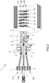
Figure 2 is a plan view of the plant; -
Figure 3 is a sectional view, along the section plane III-III ofFigure 1 ; -
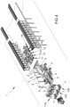
Figure 4 is a perspective view of the plant according to the present invention. - With particular reference to the numerical symbols of the aforementioned figures, the plant according to the invention, indicated as a whole with the
reference number 1, comprises a plurality of production lines, indicated with thereference numbers reference numbers - The axis of displacement of the cutters is orthogonal to the axis of the production lines, which are located on a plane below the fiberizing plane, where the dies with relative cutter are positioned.
- According to an embodiment of the invention, each production line comprises
conveyor belts 2, agranulator 3, a dryingoven 4, a vibratingscreen 5, a system for detecting metallic components and waste, and apackaging device 7. - In the embodiment proposed here, each single production line, 110, 120, 130, is capable of managing up to three cutters, and therefore three dies, at the same time.
- The
plant 1, described here by way of example, represents the application of the invention on six dies for the production of three different products A, B, and C. - Products A, B, and C can differ from each other in, for example: micronage, length of cut, binder chemistry.
- As illustrated in the figures, each of the products has its own production line consisting of dedicated equipment.
- The three lines, 110, 120, 130, comprise similar components, therefore it is possible, for instance, to produce three similar products A, B, and C, if necessary, to reach a condition similar to the already known condition in which there is no product differentiation.
- The condition shown in the embodiment described here is the following:
- cutter 11 on production line 120 (product B)
-
cutter 12 on production line 110 (product A) -
cutter 13 on production line 110 (product A) -
cutter 14 on production line 130 (product C) - cutter 15 on production line 120 (product B)
-
cutter 16 on production line 130 (product C) - Should it be necessary to increase the production of a specific product, the system's flexibility allows to move a cutter on to the relevant line.
- For example, in the event of an increase in demand for product C, the
cutter 15 can be moved into position online 130. - It has been seen in practice that this invention achieves the intended aim and objects.
- In fact, the plant according to the invention has considerable advantages over the plants of the prior art.
- Compared to the prior art systems, in fact the present invention can manage the production in a capillary manner.
- By way of example, assuming there are two production lines relating to two products A and B, it is possible to position the
cutters line 110 while thecutters line 120. - Following a production request, the system allows to quickly move the
cutter 12, (for example), fromline 110 toline 120. - In this way, the production batches are considerably reduced, simultaneously reducing the risk of losing the order due to lack of the specific product required by the market, while also reducing the need to build up stock.
- It must in fact be borne in mind that glass fiber products are products that generally have an expiry date, a fact that increases the economic risk of building up stock.
- The prior art systems require many production changes in order to closely follow the customer's request.
- On the contrary, with the plant according to the present invention, equipped with individual cutters, it is possible to produce different types of products at the same time, introducing greater flexibility.
- The present invention allows to lower the production changeover costs for a like level of productivity, thus reducing all the losses associated with production changeover.
- The materials used, as well as the dimensions, may be adapted to meet any needs.
Claims (9)
- A glass fiber cutting plant, characterized in that it comprises a plurality of production lines (110, 120, 130), and a matrix system, having a plurality of cutters (11, 12, 13, 14, 15, 16); each of said cutters corresponding to a specific die and being movable from one of said production lines to another.
- The plant according to claim 1, characterized in that each of said cutters (11, 12, 13, 14, 15, 16) has a displacement axis; said displacement axis being orthogonal to the axis of said production lines (110, 120, 130), said production lines (110, 120, 130) being arranged in a plane below the fiberizing plane, where the dies with relative cutter are positioned.
- The plant according to claim 1, characterized in that each of said production lines (110, 120, 130) comprises conveyor belts (2).
- The plant according to claim 1, characterized in that each of said production lines (110, 120, 130) comprises a granulator (3).
- The plant according to claim 1, characterized in that each of said production lines (110, 120, 130) comprises a drying oven (4).
- The plant according to claim 1, characterized in that each of said production lines (110, 120, 130) comprises a vibrating screen (5).
- The plant according to claim 1, characterized in that each of said production lines (110, 120, 130) comprises a system for detecting metallic components and waste.
- The plant according to claim 1, characterized in that each of said production lines (110, 120, 130) comprises a packaging device (7).
- The plant, according to claim 1, characterized in that each of said production lines (110, 120, 130) manages up to three cutters (11, 12, 13, 14, 15, 16) and three dies at the same time.
Applications Claiming Priority (1)
| Application Number | Priority Date | Filing Date | Title |
|---|---|---|---|
| IT102021000002840A IT202100002840A1 (en) | 2021-02-09 | 2021-02-09 | HIGHLY FLEXIBLE FIBERGLASS CUTTING PLANT |
Publications (3)
| Publication Number | Publication Date |
|---|---|
| EP4052873A1 EP4052873A1 (en) | 2022-09-07 |
| EP4052873B1 true EP4052873B1 (en) | 2023-08-16 |
| EP4052873C0 EP4052873C0 (en) | 2023-08-16 |
Family
ID=75539837
Family Applications (1)
| Application Number | Title | Priority Date | Filing Date |
|---|---|---|---|
| EP22155012.2A Active EP4052873B1 (en) | 2021-02-09 | 2022-02-03 | High flexibility cutting plant for glass fiber |
Country Status (3)
| Country | Link |
|---|---|
| EP (1) | EP4052873B1 (en) |
| CN (1) | CN114907008A (en) |
| IT (1) | IT202100002840A1 (en) |
Family Cites Families (9)
| Publication number | Priority date | Publication date | Assignee | Title |
|---|---|---|---|---|
| US4194896A (en) * | 1978-08-28 | 1980-03-25 | Owens-Corning Fiberglas Corporation | Method and apparatus for forming glass filaments |
| FR2490251A1 (en) * | 1980-09-12 | 1982-03-19 | Saint Gobain Vetrotex | METHOD AND DEVICE FOR INTRODUCING A CONTINUOUS WIRE IN A CUTTING MACHINE |
| US4551160A (en) * | 1984-10-22 | 1985-11-05 | Owens-Corning Fiberglas Corporation | Method and apparatus for forming glass filaments |
| US5935289A (en) * | 1994-08-25 | 1999-08-10 | Johns Manville International, Inc. | Apparatus for automatic fiber manufacture |
| FR2804974B1 (en) * | 2000-02-16 | 2002-06-28 | Vetrotex France Sa | SYSTEM FOR MANUFACTURING THERMOPLASTIC CUT WIRES |
| JP4180354B2 (en) * | 2002-11-18 | 2008-11-12 | Dic株式会社 | Short glass fiber cutting device and sheet molding compound manufacturing method |
| EP3277868B1 (en) * | 2015-04-03 | 2021-11-24 | Bright Lite Structures LLC | Apparatus for controllably cutting fibers and related methods |
| CN210969104U (en) * | 2019-09-23 | 2020-07-10 | 赣州汇利通新材料有限公司 | Cutting device is used in FRP pipe material processing |
| CN111016222A (en) * | 2019-12-28 | 2020-04-17 | 山东金利德机械股份有限公司 | Fiber reinforced composite material flat belt production method and supporting production line |
-
2021
- 2021-02-09 IT IT102021000002840A patent/IT202100002840A1/en unknown
-
2022
- 2022-01-29 CN CN202210112625.1A patent/CN114907008A/en active Pending
- 2022-02-03 EP EP22155012.2A patent/EP4052873B1/en active Active
Also Published As
| Publication number | Publication date |
|---|---|
| EP4052873A1 (en) | 2022-09-07 |
| IT202100002840A1 (en) | 2022-08-09 |
| CN114907008A (en) | 2022-08-16 |
| EP4052873C0 (en) | 2023-08-16 |
Similar Documents
| Publication | Publication Date | Title |
|---|---|---|
| EP1048621A2 (en) | Method and apparatus for making single glass sheets | |
| CA1129205A (en) | Method and apparatus for forming glass filaments | |
| EP4052873A1 (en) | High flexibility cutting plant for glass fiber | |
| EP0584325B1 (en) | Device for cooling and granulating molten thermoplastic strands emerging from dies | |
| EP0305460B1 (en) | Strand granulator with counter-blade that can be changed during operation | |
| US2947028A (en) | Apparatus for manufacture of fibrous glass | |
| EP1516860B1 (en) | Apparatus and method for the production of glass fibres | |
| US7735341B2 (en) | System for making clipped thermoplastic yarns | |
| US3767372A (en) | Apparatus for manufacturing a multi-filament light conducting cable | |
| US5746798A (en) | Control of glass gob delivery for simultaneous arrival at blank molds | |
| EP1266869B1 (en) | Process and apparatus for simultaneous production of glass products of differing weight | |
| EP0281300B1 (en) | Gob distributor | |
| US3055051A (en) | Spinning of glass or other thermoplastic masses from rods | |
| US4268292A (en) | Method and apparatus for forming glass filaments | |
| US3727038A (en) | Apparatus for manufacturing welded wire mesh mats for reinforcing concrete | |
| US20110008482A1 (en) | System for the manufactur of chopped strands made of thermoplastic material | |
| US4369051A (en) | Apparatus for handling linear elements | |
| WO2009052978A1 (en) | Strand pelletizer | |
| US2763100A (en) | Apparatus for guiding and spreading fibers | |
| US1526518A (en) | Machine for and method of forming ring travelers | |
| US3844191A (en) | Apparatus for severing linear elements | |
| KR20040010534A (en) | Method and apparatus for reshaping the draw end of an optical fiber preform | |
| US3265478A (en) | Method for forming crystal-free glass fibers | |
| WO2003016227A1 (en) | Device and method for regulating and/or controlling at least one feeder unit of a glass-forming machine | |
| EP0801036B1 (en) | Method for controlling the blank molds of a glass-machine with several like sections next to each other |
Legal Events
| Date | Code | Title | Description |
|---|---|---|---|
| PUAI | Public reference made under article 153(3) epc to a published international application that has entered the european phase |
Free format text: ORIGINAL CODE: 0009012 |
|
| STAA | Information on the status of an ep patent application or granted ep patent |
Free format text: STATUS: THE APPLICATION HAS BEEN PUBLISHED |
|
| AK | Designated contracting states |
Kind code of ref document: A1 Designated state(s): AL AT BE BG CH CY CZ DE DK EE ES FI FR GB GR HR HU IE IS IT LI LT LU LV MC MK MT NL NO PL PT RO RS SE SI SK SM TR |
|
| STAA | Information on the status of an ep patent application or granted ep patent |
Free format text: STATUS: REQUEST FOR EXAMINATION WAS MADE |
|
| 17P | Request for examination filed |
Effective date: 20221130 |
|
| GRAP | Despatch of communication of intention to grant a patent |
Free format text: ORIGINAL CODE: EPIDOSNIGR1 |
|
| STAA | Information on the status of an ep patent application or granted ep patent |
Free format text: STATUS: GRANT OF PATENT IS INTENDED |
|
| INTG | Intention to grant announced |
Effective date: 20230405 |
|
| GRAS | Grant fee paid |
Free format text: ORIGINAL CODE: EPIDOSNIGR3 |
|
| GRAA | (expected) grant |
Free format text: ORIGINAL CODE: 0009210 |
|
| STAA | Information on the status of an ep patent application or granted ep patent |
Free format text: STATUS: THE PATENT HAS BEEN GRANTED |
|
| AK | Designated contracting states |
Kind code of ref document: B1 Designated state(s): AL AT BE BG CH CY CZ DE DK EE ES FI FR GB GR HR HU IE IS IT LI LT LU LV MC MK MT NL NO PL PT RO RS SE SI SK SM TR |
|
| REG | Reference to a national code |
Ref country code: CH Ref legal event code: EP |
|
| REG | Reference to a national code |
Ref country code: DE Ref legal event code: R096 Ref document number: 602022000322 Country of ref document: DE |
|
| REG | Reference to a national code |
Ref country code: IE Ref legal event code: FG4D |
|
| U01 | Request for unitary effect filed |
Effective date: 20230830 |
|
| U07 | Unitary effect registered |
Designated state(s): AT BE BG DE DK EE FI FR IT LT LU LV MT NL PT SE SI Effective date: 20230906 |
|
| PG25 | Lapsed in a contracting state [announced via postgrant information from national office to epo] |
Ref country code: GR Free format text: LAPSE BECAUSE OF FAILURE TO SUBMIT A TRANSLATION OF THE DESCRIPTION OR TO PAY THE FEE WITHIN THE PRESCRIBED TIME-LIMIT Effective date: 20231117 |
|
| PG25 | Lapsed in a contracting state [announced via postgrant information from national office to epo] |
Ref country code: IS Free format text: LAPSE BECAUSE OF FAILURE TO SUBMIT A TRANSLATION OF THE DESCRIPTION OR TO PAY THE FEE WITHIN THE PRESCRIBED TIME-LIMIT Effective date: 20231216 |
|
| PG25 | Lapsed in a contracting state [announced via postgrant information from national office to epo] |
Ref country code: RS Free format text: LAPSE BECAUSE OF FAILURE TO SUBMIT A TRANSLATION OF THE DESCRIPTION OR TO PAY THE FEE WITHIN THE PRESCRIBED TIME-LIMIT Effective date: 20230816 Ref country code: NO Free format text: LAPSE BECAUSE OF FAILURE TO SUBMIT A TRANSLATION OF THE DESCRIPTION OR TO PAY THE FEE WITHIN THE PRESCRIBED TIME-LIMIT Effective date: 20231116 Ref country code: IS Free format text: LAPSE BECAUSE OF FAILURE TO SUBMIT A TRANSLATION OF THE DESCRIPTION OR TO PAY THE FEE WITHIN THE PRESCRIBED TIME-LIMIT Effective date: 20231216 Ref country code: HR Free format text: LAPSE BECAUSE OF FAILURE TO SUBMIT A TRANSLATION OF THE DESCRIPTION OR TO PAY THE FEE WITHIN THE PRESCRIBED TIME-LIMIT Effective date: 20230816 Ref country code: GR Free format text: LAPSE BECAUSE OF FAILURE TO SUBMIT A TRANSLATION OF THE DESCRIPTION OR TO PAY THE FEE WITHIN THE PRESCRIBED TIME-LIMIT Effective date: 20231117 |
|
| PG25 | Lapsed in a contracting state [announced via postgrant information from national office to epo] |
Ref country code: PL Free format text: LAPSE BECAUSE OF FAILURE TO SUBMIT A TRANSLATION OF THE DESCRIPTION OR TO PAY THE FEE WITHIN THE PRESCRIBED TIME-LIMIT Effective date: 20230816 |
|
| RAP2 | Party data changed (patent owner data changed or rights of a patent transferred) |
Owner name: DIETZE & SCHELL MASCHINENFABRIK GMBH & CO. KG |
|
| U1K | Transfer of rights of the unitary patent after the registration of the unitary effect |
Owner name: DIETZE & SCHELL MASCHINENFABRIK GMBH & CO. KG; DE |
|
| U1N | Appointed representative for the unitary patent procedure changed after the registration of the unitary effect |
Representative=s name: DAUB, THOMAS; DE |
|
| U20 | Renewal fee for the european patent with unitary effect paid |
Year of fee payment: 3 Effective date: 20240219 |
|
| PG25 | Lapsed in a contracting state [announced via postgrant information from national office to epo] |
Ref country code: ES Free format text: LAPSE BECAUSE OF FAILURE TO SUBMIT A TRANSLATION OF THE DESCRIPTION OR TO PAY THE FEE WITHIN THE PRESCRIBED TIME-LIMIT Effective date: 20230816 |
|
| PG25 | Lapsed in a contracting state [announced via postgrant information from national office to epo] |
Ref country code: SM Free format text: LAPSE BECAUSE OF FAILURE TO SUBMIT A TRANSLATION OF THE DESCRIPTION OR TO PAY THE FEE WITHIN THE PRESCRIBED TIME-LIMIT Effective date: 20230816 Ref country code: RO Free format text: LAPSE BECAUSE OF FAILURE TO SUBMIT A TRANSLATION OF THE DESCRIPTION OR TO PAY THE FEE WITHIN THE PRESCRIBED TIME-LIMIT Effective date: 20230816 Ref country code: ES Free format text: LAPSE BECAUSE OF FAILURE TO SUBMIT A TRANSLATION OF THE DESCRIPTION OR TO PAY THE FEE WITHIN THE PRESCRIBED TIME-LIMIT Effective date: 20230816 Ref country code: CZ Free format text: LAPSE BECAUSE OF FAILURE TO SUBMIT A TRANSLATION OF THE DESCRIPTION OR TO PAY THE FEE WITHIN THE PRESCRIBED TIME-LIMIT Effective date: 20230816 Ref country code: SK Free format text: LAPSE BECAUSE OF FAILURE TO SUBMIT A TRANSLATION OF THE DESCRIPTION OR TO PAY THE FEE WITHIN THE PRESCRIBED TIME-LIMIT Effective date: 20230816 |
|
| REG | Reference to a national code |
Ref country code: DE Ref legal event code: R097 Ref document number: 602022000322 Country of ref document: DE |
|
| PLBE | No opposition filed within time limit |
Free format text: ORIGINAL CODE: 0009261 |
|
| STAA | Information on the status of an ep patent application or granted ep patent |
Free format text: STATUS: NO OPPOSITION FILED WITHIN TIME LIMIT |
|
| 26N | No opposition filed |
Effective date: 20240517 |
|
| PG25 | Lapsed in a contracting state [announced via postgrant information from national office to epo] |
Ref country code: MC Free format text: LAPSE BECAUSE OF FAILURE TO SUBMIT A TRANSLATION OF THE DESCRIPTION OR TO PAY THE FEE WITHIN THE PRESCRIBED TIME-LIMIT Effective date: 20230816 |
|
| PG25 | Lapsed in a contracting state [announced via postgrant information from national office to epo] |
Ref country code: IE Free format text: LAPSE BECAUSE OF NON-PAYMENT OF DUE FEES Effective date: 20240203 |
|
| PG25 | Lapsed in a contracting state [announced via postgrant information from national office to epo] |
Ref country code: IE Free format text: LAPSE BECAUSE OF NON-PAYMENT OF DUE FEES Effective date: 20240203 |
|
| U20 | Renewal fee for the european patent with unitary effect paid |
Year of fee payment: 4 Effective date: 20250219 |
|
| PG25 | Lapsed in a contracting state [announced via postgrant information from national office to epo] |
Ref country code: CY Free format text: LAPSE BECAUSE OF FAILURE TO SUBMIT A TRANSLATION OF THE DESCRIPTION OR TO PAY THE FEE WITHIN THE PRESCRIBED TIME-LIMIT; INVALID AB INITIO Effective date: 20220203 |
|
| REG | Reference to a national code |
Ref country code: CH Ref legal event code: PL |
|
| PG25 | Lapsed in a contracting state [announced via postgrant information from national office to epo] |
Ref country code: CH Free format text: LAPSE BECAUSE OF NON-PAYMENT OF DUE FEES Effective date: 20250228 |
|
| U20 | Renewal fee for the european patent with unitary effect paid |
Year of fee payment: 5 Effective date: 20260210 |
|
| PGFP | Annual fee paid to national office [announced via postgrant information from national office to epo] |
Ref country code: TR Payment date: 20260129 Year of fee payment: 5 |