EP4052803A1 - Coating film, automobile, and coating method - Google Patents
Coating film, automobile, and coating method Download PDFInfo
- Publication number
- EP4052803A1 EP4052803A1 EP20880638.0A EP20880638A EP4052803A1 EP 4052803 A1 EP4052803 A1 EP 4052803A1 EP 20880638 A EP20880638 A EP 20880638A EP 4052803 A1 EP4052803 A1 EP 4052803A1
- Authority
- EP
- European Patent Office
- Prior art keywords
- car body
- coating film
- protruding portions
- automobile
- coating
- Prior art date
- Legal status (The legal status is an assumption and is not a legal conclusion. Google has not performed a legal analysis and makes no representation as to the accuracy of the status listed.)
- Pending
Links
Images




Classifications
-
- B—PERFORMING OPERATIONS; TRANSPORTING
- B05—SPRAYING OR ATOMISING IN GENERAL; APPLYING FLUENT MATERIALS TO SURFACES, IN GENERAL
- B05D—PROCESSES FOR APPLYING FLUENT MATERIALS TO SURFACES, IN GENERAL
- B05D1/00—Processes for applying liquids or other fluent materials
- B05D1/26—Processes for applying liquids or other fluent materials performed by applying the liquid or other fluent material from an outlet device in contact with, or almost in contact with, the surface
-
- B—PERFORMING OPERATIONS; TRANSPORTING
- B05—SPRAYING OR ATOMISING IN GENERAL; APPLYING FLUENT MATERIALS TO SURFACES, IN GENERAL
- B05D—PROCESSES FOR APPLYING FLUENT MATERIALS TO SURFACES, IN GENERAL
- B05D5/00—Processes for applying liquids or other fluent materials to surfaces to obtain special surface effects, finishes or structures
- B05D5/02—Processes for applying liquids or other fluent materials to surfaces to obtain special surface effects, finishes or structures to obtain a matt or rough surface
-
- B—PERFORMING OPERATIONS; TRANSPORTING
- B05—SPRAYING OR ATOMISING IN GENERAL; APPLYING FLUENT MATERIALS TO SURFACES, IN GENERAL
- B05D—PROCESSES FOR APPLYING FLUENT MATERIALS TO SURFACES, IN GENERAL
- B05D7/00—Processes, other than flocking, specially adapted for applying liquids or other fluent materials to particular surfaces or for applying particular liquids or other fluent materials
- B05D7/14—Processes, other than flocking, specially adapted for applying liquids or other fluent materials to particular surfaces or for applying particular liquids or other fluent materials to metal, e.g. car bodies
-
- B—PERFORMING OPERATIONS; TRANSPORTING
- B05—SPRAYING OR ATOMISING IN GENERAL; APPLYING FLUENT MATERIALS TO SURFACES, IN GENERAL
- B05D—PROCESSES FOR APPLYING FLUENT MATERIALS TO SURFACES, IN GENERAL
- B05D7/00—Processes, other than flocking, specially adapted for applying liquids or other fluent materials to particular surfaces or for applying particular liquids or other fluent materials
- B05D7/50—Multilayers
- B05D7/52—Two layers
-
- B—PERFORMING OPERATIONS; TRANSPORTING
- B62—LAND VEHICLES FOR TRAVELLING OTHERWISE THAN ON RAILS
- B62D—MOTOR VEHICLES; TRAILERS
- B62D35/00—Vehicle bodies characterised by streamlining
-
- B—PERFORMING OPERATIONS; TRANSPORTING
- B05—SPRAYING OR ATOMISING IN GENERAL; APPLYING FLUENT MATERIALS TO SURFACES, IN GENERAL
- B05D—PROCESSES FOR APPLYING FLUENT MATERIALS TO SURFACES, IN GENERAL
- B05D1/00—Processes for applying liquids or other fluent materials
- B05D1/02—Processes for applying liquids or other fluent materials performed by spraying
Definitions
- Disclosed embodiments relate to a coating film, an automobile, and a coating method.
- a coating film according to one aspect of embodiments is located on the surface of a car body of an automobile and includes a plurality of protruding portions extending along the car body in a direction intersecting the length direction of the car body.
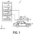
- FIG. 1 is an explanatory diagram illustrating an example of a coating device.
- FIG. 1 illustrates a three-dimensional orthogonal coordinate system including a Z-axis in which the vertically upward direction is a positive direction and the vertically downward direction is a negative direction.
- Such orthogonal coordinate systems may also be presented in other drawings used in the description below.
- the same components as those of a coating device 1 illustrated in FIG. 1 are denoted by the same reference numerals, and descriptions thereof will be omitted or simplified.
- the coating device 1 includes a head 10, a robot 20, and a control device 40.
- the head 10 is fixed to the robot 20.
- the head 10 moves according to the operation of the robot 20 controlled by the control device 40.
- the head 10 coats a car body 30 by depositing a coating material discharged from a plurality of discharge holes 11 located on a nozzle surface 12 onto a surface of the car body 30 to be coated, facing the nozzle surface 12.
- the head 10 is supplied with a coating material from a tank (not illustrated).
- the head 10 discharges the coating material supplied from the tank.
- the coating material is a mixture including a volatile component and a nonvolatile component, and has fluidity.
- the tank may be a reservoir (not illustrated) contained in the head 10.
- the volatile component is, for example, water, organic solvent, or alcohol and adjusts the physical properties of the coating materials, such as viscosity and surface tension.
- the nonvolatile component includes, for example, a pigment, a resin material, and an additive.
- the pigment includes one or a plurality of colored pigments used depending on the desired coating color.
- the resin material adheres to the car body 30 to be coated to form a film.
- the additive is a functional material that is added, for example for purposes of weather resistance.
- the coating material supplied to the discharge holes 11 is prepared such that a desired coating color is expressed by mixing a plurality of colored pigments or coating materials at predetermined proportions.
- the robot 20 holds the head 10.
- the robot 20 is, for example, a six-axis articulated robot.
- the robot 20 may be, for example, a vertical articulated robot or a horizontal articulated robot.
- the robot 20 includes a plurality of arms 21 each of which has the head 10 fixed to a tip of the arm 21.
- the robot 20 is fixed to, for example, a floor, a wall, or a ceiling. Note that as long as the held head 10 can be moved properly, there is no limit to the degree of freedom of the arms 21 included in the robot 20.
- the control device 40 controls the coating device 1.
- the control device 40 includes a controller 41 that controls the coating device 1, and a storage unit 45.
- the controller 41 includes a discharge controller 42 and an operation controller 43.
- the controller 41 includes a computer or various circuits including, for example, a central processing unit (CPU), a read only memory (ROM), a random access memory (RAM), a hard desk drive (HDD), and an input/output port.
- the CPU of such a computer functions as the controller 41 by, for example, reading and executing a program stored in the ROM.
- the controller 41 may also include hardware such as an application specific integrated circuit (ASIC) or a field programmable gate array (FPGA).
- the discharge controller 42 controls the head 10 based on the configuration information stored in the storage unit 45, and discharges the coating material from the plurality of discharge holes 11 toward the car body 30.
- the operation controller 43 controls operations of the plurality of arms 21 based on the configuration information stored in the storage unit 45, and controls movement of the head 10 via the arms 21.
- the distance between the head 10 and the car body 30 is maintained at, for example, approximately from 0.5 to 14 mm.
- the storage unit 45 corresponds to, for example, the ROM and the HDD.
- the ROM and the HDD can store the configuration information for various controls in the control device 40.
- the storage unit 45 stores information related to discharge control of the coating material by the head 10. Further, the storage unit 45 stores information related to the operation control of the plurality of arms 21.
- the storage unit 45 may store data input by the user's instruction operation using a terminal apparatus (not illustrated) as instruction data for operating the robot 20. Further, the controller 41 may also obtain the configuration information via another computer or portable storage medium connected by a wired or wireless network.
- the car body 30 is a car body of an automobile.
- the car body 30 is placed on a conveying device (not illustrated), and is carried in and out.
- the coating device 1 according to an embodiment coats the car body 30 in a state where the conveying device is stopped.
- the coating device 1 may coat the car body 30 while the car body 30 is being repeatedly conveyed and stopped, or may coat the car body 30 simultaneously while the car body 30 is being conveyed.
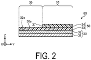
- FIG. 2 is a cross-sectional view illustrating an example of an automobile according to an embodiment.
- An automobile 60 illustrated in FIG. 2 includes a base member 31, a primer layer 32, a first coating layer 33, and a second coating layer 34.
- the automobile 60 includes one or a plurality of power sources, such as an engine or a motor, and refers to a vehicle running on a road with three or more wheels without using rails or overhead lines.
- the automobile 60 may be, for example, a private vehicle or a commercial vehicle, and there is no limitation on the use of the automobile 60.
- the base member 31 is, for example, a steel plate processed into a predetermined shape, and is subjected to an electrodeposition process as necessary to impart rust resistance.
- the primer layer 32 is provided for imparting weather resistance, color development, and peeling resistance, for example.
- the first coating layer 33 is, for example, a base layer that has smoothness and weather resistance and imparts a desired coating color. A surface of the first coating layer 33 serves as a to-be-coated surface 30a to be coated by the coating device 1 according to the embodiment.
- a second coating layer 34 is located on the first coating layer 33 serving as the to-be-coated surface 30a.
- the second coating layer 34 is located in a manner to cover a portion of the first coating layer 33, for example, with a coating material having a coating color different from that of the first coating layer 33.
- the car body 30 becomes a coated automobile 60 that is coated in a so-called two tone color in which a region 36 where the second coating layer 34 is located and a region 35 where the first coating layer 33 is exposed without the second coating layer 34 being located are aligned with an end portion 37 of the second coating layer 34 as a boundary.
- the coating device 1 arranges the second coating layer 34 on the to-be-coated surface 30a on the first coating layer 33, but the embodiments are not limited to the example, and the coating device 1 may be used, for example, to arrange the first coating layer 33 on a coated surface 32a of the primer layer 32.
- the automobile 60 is not limited to the example illustrated in FIG. 2 .
- a coating layer (not illustrated) may be located on the surface of the region 35 or 36.
- the second coating layer 34 may not be provided, and only the first coating layer 33 may be provided, or the second coating layer 34 may be located on the entire surface of the first coating layer 33.
- the car body 30 or the automobile 60 may further include one or a plurality of layers (not illustrated).
- the first coating layer 33 and the second coating layer 34 are collectively referred to as a coating film 50 without distinction, and the base member 31 and the primer layer 32 are collectively referred to as the car body 30 without distinction.
- FIG. 3 is a plan view illustrating an example of an automobile according to a first embodiment.
- FIG. 4 is a cross-sectional view taken along line A-A in FIG. 3 .
- FIG. 5 is a side view illustrating an example of an automobile according to the first embodiment.
- An automobile 60 includes a plurality of protrusions 55 in a direction intersecting the length direction (Y axis direction) of a car body 30.
- the plurality of protruding portions 55 are formed along the car body 30 in the direction intersecting Y axis direction on the surfaces of the coating film 50 coated on, for example, a roof 65, a trunk 69, and a rear portion 67 of a side face 63 of the car body 30.
- the plurality of protruding portions 55 are formed along the car body 30 in the width direction (X axis direction) intersecting the length direction (Y axis direction) of the car body 30.
- each protruding portion 55 is formed along the car body 30 in the height direction (Z axis direction) intersecting the length direction (Y axis direction) of the car body 30.
- Each protruding portion 55 has a shape extending along the car body 30 in the direction intersecting the length direction (Y axis direction) of the car body 30 (for example, the width direction or the height direction of the car body 30). That is, at the roof 65 and the trunk 69, each protruding portion 55 has a shape extending along the car body 30 in the width direction of the car body 30.
- each protruding portion 55 has a shape extending along the car body 30 in the height direction of the car body 30.
- the plurality of protruding portions 55 are aligned in the length direction of the car body 30 along the car body 30.
- the plurality of protruding portions 55 protrude in the thickness direction of the coating film 50 on the surface of the coating film 50, and may be formed, for example, by a difference in the thickness of the coating film 50. That is, the thickness of the coating film 50 can be made thicker in the protruding portion 55 than in the portion where the protruding portion 55 is not arranged.
- the protruding portion 55 is formed by the difference in the thickness of the coating film 50, the protruding portion 55 can be easily formed at the time of coating by using, for example, an inkjet head to change the discharge amount of the coating material depending on the location.
- a coating method can be used in which a coating material is discharged toward the to-be-coated surface of the car body 30 and a plurality of protruding portions 55 extending in the direction intersecting the length direction (Y axis direction) of the car body 30 are formed on the surface of the coating film.
- the difference in thickness of the coating film 50 the difference in thickness of the base member 31 or the primer layer 32 may form the protruding portion 55 on the surface of the coating film 50, and the curvature of the base member 31 may form the protruding portion 55 on the surface of the coating film 50.
- the height h, the width, and the interval d of the protruding portion 55 may be, for example, approximately 20 ⁇ m to 150 ⁇ m.
- the coating film 50 on the surface of the car body 30 includes the plurality of protruding portions 55 extending along the car body 30 in the direction intersecting the length direction of the car body 30. That is, the automobile 60 includes the plurality of protruding portions 55 extending along the car body 30 in the direction intersecting the length direction of the car body 30 on the surface of the coating film 50. This allows the automobile 60 to obtain the effect of reducing pressure resistance due to reduction of boundary layer separation by causing turbulence during travel.
- the shape, the size, the arrangement, or the like of the protruding portion 55 can be appropriately set in consideration of both the reduction effect of the pressure resistance and the increase in the friction resistance.
- the plurality of protruding portions 55 are provided in a portion (for example, the portion indicated by P1 in FIG. 3 ) located in front (front end 61 side) of a portion (in FIG.
- the effect of reducing the peeling of the boundary layer can be enhanced, thereby increasing the effect of reducing the pressure resistance of the automobile 60.
- the dimensions such as the height h, the width, and the interval d of the protruding portion 55 described above are not limited to the numerical range described above, and may be made smaller or larger. For example, when it is desired to increase the effect of generating turbulence, it is effective to increase the height h of the protruding portion 55.
- the dimensions such as the height h, the width, and the interval d of the protruding portion 55 may be substantially different from each other.
- the plurality of protruding portions 55 are provided only on the rear side of the roof 65, but the embodiments are not limited to such a configuration, and may be provided throughout the roof 65. Further, the plurality of protruding portions 55 may be provided on the surface of the coating film 50 coated on each of the bonnet 64 and the side face door 66.
- FIG. 6 is a plan view illustrating an example of an automobile according to a second embodiment.
- the center portions of a plurality of protruding portions 55 extending in the width direction of a car body 30 are formed in a curved so as to be located closer to a rear end 62 of the car body 30 than end portions.
- the center portions of the plurality of protruding portions 55 located on a side face 63 of the car body 30 and extending in the height direction of the car body 30 are formed in a curved shape so as to be located closer to the rear end 62 of the car body 30 than end portions. Also, unless otherwise noted, the same applies to each of the embodiments described below.
- FIG. 7 is a plan view illustrating an example of an automobile according to a third embodiment.
- An automobile 60 according to the third embodiment includes a plurality of protruding portions 55 extending in a direction inclined with respect to the width direction of a car body 30 in a manner to be folded back across a plurality of bent portions 57. That is, each of the plurality of protruding portions 55 includes the plurality of bent portions 57 and extends as a whole along the car body 30 in the direction intersecting the length direction of the car body 30 while changing the direction to extend at the plurality of bent portions 57.
- the automobile 60 has such a configuration, the effect of facilitating the occurrence of turbulence can be enhanced.
- FIG. 8 is a plan view illustrating an example of an automobile according to a fourth embodiment.
- a plurality of protruding portions 55 are bent toward a rear end 62 side of a car body 30 at end portions 55a and 55b in the width direction of the car body 30. That is, the plurality of protruding portions 55 are bent at the end portions in the length direction of the protruding portions 55.
- the effect of facilitating the occurrence of turbulence can be enhanced.
- FIG. 9 is a plan view illustrating an example of an automobile according to a fifth embodiment.
- the shapes of a plurality of protruding portions 55 located on a roof 65 and a trunk 69 are different from each other.
- the plurality of protruding portions 55 located on the roof 65 are formed in a curved shape such that end portions of each of the plurality of protruding portion 55 extending in the width direction of a car body 30 are located closer to a rear end 62 of the car body 30 than the center portion.
- the plurality of protruding portions 55 located on the trunk 69 includes a plurality of protruding portions 55 extending in a direction inclined with respect to the width direction of the car body 30 in a manner to be folded back across a plurality of bent portions 57. Moreover, both ends in the length direction of each protruding portion 55 extend toward the rear end 62 side of the car body 30. In this way, the plurality of protrusions 55 having different shapes may be arranged in different locations (for example, the roof 65 and the trunk 69) from each other. When the automobile 60 has such a configuration, the effect of facilitating the occurrence of turbulence can be enhanced.
- the combination of the plurality of protruding portions 55 having different shapes are not limited to those illustrated in the drawings, and the protruding portions 55 having various shapes including the protruding portions 55 according to each of the above-described embodiments can be appropriately combined. Additionally, a plurality of protruding portions 55 having a shape similar to the protruding portions 55 located on the roof 65 may be formed on the trunk 69, or a plurality of protruding portions 55 having a shape similar to the protruding portions 55 located on the trunk 69 may be formed on the roof 65.
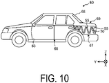
- FIG. 10 is a side view illustrating an example of an automobile according to a sixth embodiment.
- a plurality of protruding portions extend in different directions.
- each of a plurality of protruding portions 55 located on a side face 63 of a car body 30 extend in a direction inclined from the height direction (Z axis direction) of the car body 30 along the car body 30.
- the adjacent protruding portions 55 may be spaced apart as illustrated, or part or all of the adjacent protruding portions 55 may be integrally formed.
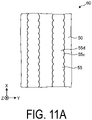
- FIGS. 11A and 11B are plan views illustrating examples of automobiles according to the first and second modifications, respectively.
- a protruding portion 55 illustrated in FIG. 11A includes a first portion 55c and a second portion 55d having different sizes in the width direction (Y axis direction) intersecting the length direction (X axis direction) of the protruding portion 55.
- a protruding portion 55 illustrated in FIG. 11B includes portions different in magnitude in the height direction (Z axis direction) intersecting the length direction (X axis direction) of the protruding portion 55. In this manner, each protruding portion 55 may vary in shape in the length direction.
- FIG. 11A and 11B illustrate an example of the plurality of protruding portions 55 formed in the roof 65 or the bonnet 64
- the plurality of protruding portions 55 formed on the side face door 66 may similarly have different sizes in the width direction (Y axis direction) or the height direction (X axis direction) intersecting the length direction (Z axis direction) of the protruding portion 55.
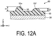
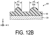
- FIGS. 12A to 12C are cross-sectional views illustrating examples of automobiles according to the third to fifth modifications, respectively.
- An automobile 60 illustrated in FIG. 12A includes a protruding portion 55e having a height direction (Z axis direction) size of h1 and a protruding portion 55f having a height direction (Z axis direction) size of h2 (where h1 > h2).
- An automobile 60 illustrated in FIG. 12B includes a protruding portion 55g having a width direction (Y axis direction) size of w1 and a protruding portion 55 h having a width direction (Y axis direction) size of w2 (where w1 ⁇ w2). Further, an automobile 60 illustrated in FIG.
- the 12C includes a protruding portion 55 having a substantially arc-shaped cross-section, a protruding portion 55j having a substantially quadrilateral cross-section, and a substantially triangle protruding portion 55k.
- the plurality of protruding portions 55 may be different in shape from each other.
- the present invention is not limited to the embodiments described above, and various modifications are possible without departing from the spirit thereof.
- the car body 30 is illustrated as having a flat surface in each of the above embodiments, the embodiments are not limited such a configuration, and the car body 30 may have a curved surface or may be inclined.
Landscapes
- Engineering & Computer Science (AREA)
- Life Sciences & Earth Sciences (AREA)
- Wood Science & Technology (AREA)
- Chemical & Material Sciences (AREA)
- Combustion & Propulsion (AREA)
- Transportation (AREA)
- Mechanical Engineering (AREA)
- Application Of Or Painting With Fluid Materials (AREA)
- Laminated Bodies (AREA)
- Body Structure For Vehicles (AREA)
Abstract
Description
- Disclosed embodiments relate to a coating film, an automobile, and a coating method.
- For example, there has been proposed a coating method in which unevenness is provided on the surface of an object to be coated such as an automobile to enhance heat radiation.
-
- Patent Document 1:
JP 2016-93774 A - Patent Document 2:
JP 2008-253974 A - A coating film according to one aspect of embodiments is located on the surface of a car body of an automobile and includes a plurality of protruding portions extending along the car body in a direction intersecting the length direction of the car body.
-
-
FIG. 1 is an explanatory diagram illustrating an example of a coating device. -
FIG. 2 is a cross-sectional view illustrating an example of an automobile according to an embodiment. -
FIG. 3 is a plan view illustrating an example of an automobile according to a first embodiment. -
FIG. 4 is a cross-sectional view taken along line A-A inFIG. 3 . -
FIG. 5 is a side view illustrating an example of an automobile according to the first embodiment. -
FIG. 6 is a plan view illustrating an example of an automobile according to a second embodiment. -
FIG. 7 is a plan view illustrating an example of an automobile according to a third embodiment. -
FIG. 8 is a plan view illustrating an example of an automobile according to a fourth embodiment. -
FIG. 9 is a plan view illustrating an example of an automobile according to a fifth embodiment. -
FIG. 10 is a side view illustrating an example of an automobile according to a sixth embodiment. -
FIG. 11A is a plan view illustrating an example of an automobile according to a first modification. -
FIG. 11B is a cross-sectional view illustrating an example of an automobile according to a second modification. -
FIG. 12A is a cross-sectional view illustrating an example of an automobile according to a third modification. -
FIG. 12B is a cross-sectional view illustrating an example of an automobile according to a fourth modification. -
FIG. 12C is a cross-sectional view illustrating an example of an automobile according to a fifth modification. - Hereinafter, embodiments of a coating film, an automobile, and a coating method disclosed in the present application will be described in detail with reference to the accompanying drawings. The present invention is not limited by the following embodiments.
- First, an overview of a coating device used for coating a car body will be described with reference to
FIG. 1. FIG. 1 is an explanatory diagram illustrating an example of a coating device. For the sake of clarity,FIG. 1 illustrates a three-dimensional orthogonal coordinate system including a Z-axis in which the vertically upward direction is a positive direction and the vertically downward direction is a negative direction. Such orthogonal coordinate systems may also be presented in other drawings used in the description below. The same components as those of acoating device 1 illustrated inFIG. 1 are denoted by the same reference numerals, and descriptions thereof will be omitted or simplified. - As illustrated in
FIG. 1 , thecoating device 1 includes ahead 10, arobot 20, and acontrol device 40. - The
head 10 is fixed to therobot 20. Thehead 10 moves according to the operation of therobot 20 controlled by thecontrol device 40. - The
head 10 coats acar body 30 by depositing a coating material discharged from a plurality ofdischarge holes 11 located on anozzle surface 12 onto a surface of thecar body 30 to be coated, facing thenozzle surface 12. - The
head 10 is supplied with a coating material from a tank (not illustrated). Thehead 10 discharges the coating material supplied from the tank. The coating material is a mixture including a volatile component and a nonvolatile component, and has fluidity. The tank may be a reservoir (not illustrated) contained in thehead 10. - The volatile component is, for example, water, organic solvent, or alcohol and adjusts the physical properties of the coating materials, such as viscosity and surface tension. The nonvolatile component includes, for example, a pigment, a resin material, and an additive. The pigment includes one or a plurality of colored pigments used depending on the desired coating color. The resin material adheres to the
car body 30 to be coated to form a film. The additive is a functional material that is added, for example for purposes of weather resistance. - Note that the coating material supplied to the
discharge holes 11 is prepared such that a desired coating color is expressed by mixing a plurality of colored pigments or coating materials at predetermined proportions. - The
robot 20 holds thehead 10. Therobot 20 is, for example, a six-axis articulated robot. Therobot 20 may be, for example, a vertical articulated robot or a horizontal articulated robot. Therobot 20 includes a plurality ofarms 21 each of which has thehead 10 fixed to a tip of thearm 21. Therobot 20 is fixed to, for example, a floor, a wall, or a ceiling. Note that as long as the heldhead 10 can be moved properly, there is no limit to the degree of freedom of thearms 21 included in therobot 20. - The
control device 40 controls thecoating device 1. Thecontrol device 40 includes a controller 41 that controls thecoating device 1, and astorage unit 45. The controller 41 includes a discharge controller 42 and anoperation controller 43. - The controller 41 includes a computer or various circuits including, for example, a central processing unit (CPU), a read only memory (ROM), a random access memory (RAM), a hard desk drive (HDD), and an input/output port. The CPU of such a computer functions as the controller 41 by, for example, reading and executing a program stored in the ROM. The controller 41 may also include hardware such as an application specific integrated circuit (ASIC) or a field programmable gate array (FPGA). The discharge controller 42 controls the
head 10 based on the configuration information stored in thestorage unit 45, and discharges the coating material from the plurality of discharge holes 11 toward thecar body 30. Theoperation controller 43 controls operations of the plurality ofarms 21 based on the configuration information stored in thestorage unit 45, and controls movement of thehead 10 via thearms 21. The distance between thehead 10 and thecar body 30 is maintained at, for example, approximately from 0.5 to 14 mm. - The
storage unit 45 corresponds to, for example, the ROM and the HDD. The ROM and the HDD can store the configuration information for various controls in thecontrol device 40. Thestorage unit 45 stores information related to discharge control of the coating material by thehead 10. Further, thestorage unit 45 stores information related to the operation control of the plurality ofarms 21. Thestorage unit 45 may store data input by the user's instruction operation using a terminal apparatus (not illustrated) as instruction data for operating therobot 20. Further, the controller 41 may also obtain the configuration information via another computer or portable storage medium connected by a wired or wireless network. - The
car body 30 is a car body of an automobile. Thecar body 30 is placed on a conveying device (not illustrated), and is carried in and out. Thecoating device 1 according to an embodiment coats thecar body 30 in a state where the conveying device is stopped. Thecoating device 1 may coat thecar body 30 while thecar body 30 is being repeatedly conveyed and stopped, or may coat thecar body 30 simultaneously while thecar body 30 is being conveyed. -
FIG. 2 is a cross-sectional view illustrating an example of an automobile according to an embodiment. Anautomobile 60 illustrated inFIG. 2 includes a base member 31, a primer layer 32, a first coating layer 33, and asecond coating layer 34. Here, theautomobile 60 includes one or a plurality of power sources, such as an engine or a motor, and refers to a vehicle running on a road with three or more wheels without using rails or overhead lines. Theautomobile 60 may be, for example, a private vehicle or a commercial vehicle, and there is no limitation on the use of theautomobile 60. - The base member 31 is, for example, a steel plate processed into a predetermined shape, and is subjected to an electrodeposition process as necessary to impart rust resistance. The primer layer 32 is provided for imparting weather resistance, color development, and peeling resistance, for example. The first coating layer 33 is, for example, a base layer that has smoothness and weather resistance and imparts a desired coating color. A surface of the first coating layer 33 serves as a to-
be-coated surface 30a to be coated by thecoating device 1 according to the embodiment. - A
second coating layer 34 is located on the first coating layer 33 serving as the to-be-coated surface 30a. Thesecond coating layer 34 is located in a manner to cover a portion of the first coating layer 33, for example, with a coating material having a coating color different from that of the first coating layer 33. As a result, thecar body 30 becomes acoated automobile 60 that is coated in a so-called two tone color in which aregion 36 where thesecond coating layer 34 is located and aregion 35 where the first coating layer 33 is exposed without thesecond coating layer 34 being located are aligned with anend portion 37 of thesecond coating layer 34 as a boundary. - In the example illustrated in
FIG. 2 , thecoating device 1 arranges thesecond coating layer 34 on the to-be-coated surface 30a on the first coating layer 33, but the embodiments are not limited to the example, and thecoating device 1 may be used, for example, to arrange the first coating layer 33 on acoated surface 32a of the primer layer 32. - Note that the
automobile 60 is not limited to the example illustrated inFIG. 2 . For example, a coating layer (not illustrated) may be located on the surface of theregion second coating layer 34 may not be provided, and only the first coating layer 33 may be provided, or thesecond coating layer 34 may be located on the entire surface of the first coating layer 33. Further, thecar body 30 or theautomobile 60 may further include one or a plurality of layers (not illustrated). In the following description, the first coating layer 33 and thesecond coating layer 34 are collectively referred to as acoating film 50 without distinction, and the base member 31 and the primer layer 32 are collectively referred to as thecar body 30 without distinction. -
FIG. 3 is a plan view illustrating an example of an automobile according to a first embodiment.FIG. 4 is a cross-sectional view taken along line A-A inFIG. 3 .FIG. 5 is a side view illustrating an example of an automobile according to the first embodiment. - An
automobile 60 according to a first embodiment includes a plurality ofprotrusions 55 in a direction intersecting the length direction (Y axis direction) of acar body 30. The plurality of protrudingportions 55 are formed along thecar body 30 in the direction intersecting Y axis direction on the surfaces of thecoating film 50 coated on, for example, aroof 65, atrunk 69, and arear portion 67 of aside face 63 of thecar body 30. Specifically, on theroof 65 and thetrunk 69, the plurality of protrudingportions 55 are formed along thecar body 30 in the width direction (X axis direction) intersecting the length direction (Y axis direction) of thecar body 30. In addition, at therear portion 67 of theside face 63 of thecar body 30, the plurality of protrudingportions 55 are formed along thecar body 30 in the height direction (Z axis direction) intersecting the length direction (Y axis direction) of thecar body 30. Each protrudingportion 55 has a shape extending along thecar body 30 in the direction intersecting the length direction (Y axis direction) of the car body 30 (for example, the width direction or the height direction of the car body 30). That is, at theroof 65 and thetrunk 69, each protrudingportion 55 has a shape extending along thecar body 30 in the width direction of thecar body 30. Further, at therear portion 67 of theside face 63, each protrudingportion 55 has a shape extending along thecar body 30 in the height direction of thecar body 30. The plurality of protrudingportions 55 are aligned in the length direction of thecar body 30 along thecar body 30. - The plurality of protruding
portions 55 protrude in the thickness direction of thecoating film 50 on the surface of thecoating film 50, and may be formed, for example, by a difference in the thickness of thecoating film 50. That is, the thickness of thecoating film 50 can be made thicker in the protrudingportion 55 than in the portion where the protrudingportion 55 is not arranged. When the protrudingportion 55 is formed by the difference in the thickness of thecoating film 50, the protrudingportion 55 can be easily formed at the time of coating by using, for example, an inkjet head to change the discharge amount of the coating material depending on the location. That is, a coating method can be used in which a coating material is discharged toward the to-be-coated surface of thecar body 30 and a plurality of protrudingportions 55 extending in the direction intersecting the length direction (Y axis direction) of thecar body 30 are formed on the surface of the coating film. In place of the difference in thickness of thecoating film 50, the difference in thickness of the base member 31 or the primer layer 32 may form the protrudingportion 55 on the surface of thecoating film 50, and the curvature of the base member 31 may form the protrudingportion 55 on the surface of thecoating film 50. InFIG. 4 , the height h, the width, and the interval d of the protrudingportion 55 may be, for example, approximately 20 µm to 150 µm. - Thus, the
coating film 50 on the surface of thecar body 30 includes the plurality of protrudingportions 55 extending along thecar body 30 in the direction intersecting the length direction of thecar body 30. That is, theautomobile 60 includes the plurality of protrudingportions 55 extending along thecar body 30 in the direction intersecting the length direction of thecar body 30 on the surface of thecoating film 50. This allows theautomobile 60 to obtain the effect of reducing pressure resistance due to reduction of boundary layer separation by causing turbulence during travel. - Since the friction resistance during travel of the
automobile 60 may be increased due to the protrudingportion 55, the shape, the size, the arrangement, or the like of the protrudingportion 55 can be appropriately set in consideration of both the reduction effect of the pressure resistance and the increase in the friction resistance. For example, in the direction from the front toward the rear of the car body 30 (the direction from a front end 61 toward arear end 62 along the Y axis), when the plurality of protrudingportions 55 are provided in a portion (for example, the portion indicated by P1 inFIG. 3 ) located in front (front end 61 side) of a portion (inFIG. 3 , for example, near the front end of the rear glass 68) where the ratio of the decrease in the cross-sectional area (the cross-sectional area of the cross-section perpendicular to the direction from the front toward the rear of the car body 30) of thecar body 30 increases, the effect of reducing the peeling of the boundary layer can be enhanced, thereby increasing the effect of reducing the pressure resistance of theautomobile 60. - The dimensions such as the height h, the width, and the interval d of the protruding
portion 55 described above are not limited to the numerical range described above, and may be made smaller or larger. For example, when it is desired to increase the effect of generating turbulence, it is effective to increase the height h of the protrudingportion 55. The dimensions such as the height h, the width, and the interval d of the protrudingportion 55 may be substantially different from each other. - In the illustrated embodiment, the plurality of protruding
portions 55 are provided only on the rear side of theroof 65, but the embodiments are not limited to such a configuration, and may be provided throughout theroof 65. Further, the plurality of protrudingportions 55 may be provided on the surface of thecoating film 50 coated on each of thebonnet 64 and the side facedoor 66. -
FIG. 6 is a plan view illustrating an example of an automobile according to a second embodiment. - In an
automobile 60 according to the second embodiment, the center portions of a plurality of protrudingportions 55 extending in the width direction of acar body 30 are formed in a curved so as to be located closer to arear end 62 of thecar body 30 than end portions. When theautomobile 60 also has such a configuration, the effect of facilitating the occurrence of turbulence can be obtained. Although not illustrated, the center portions of the plurality of protrudingportions 55 located on aside face 63 of thecar body 30 and extending in the height direction of thecar body 30 are formed in a curved shape so as to be located closer to therear end 62 of thecar body 30 than end portions. Also, unless otherwise noted, the same applies to each of the embodiments described below. -
FIG. 7 is a plan view illustrating an example of an automobile according to a third embodiment. Anautomobile 60 according to the third embodiment includes a plurality of protrudingportions 55 extending in a direction inclined with respect to the width direction of acar body 30 in a manner to be folded back across a plurality ofbent portions 57. That is, each of the plurality of protrudingportions 55 includes the plurality ofbent portions 57 and extends as a whole along thecar body 30 in the direction intersecting the length direction of thecar body 30 while changing the direction to extend at the plurality ofbent portions 57. When theautomobile 60 has such a configuration, the effect of facilitating the occurrence of turbulence can be enhanced. -
FIG. 8 is a plan view illustrating an example of an automobile according to a fourth embodiment. In anautomobile 60 according to the fourth embodiment, a plurality of protrudingportions 55 are bent toward arear end 62 side of acar body 30 atend portions car body 30. That is, the plurality of protrudingportions 55 are bent at the end portions in the length direction of the protrudingportions 55. When theautomobile 60 has such a configuration, the effect of facilitating the occurrence of turbulence can be enhanced. -
FIG. 9 is a plan view illustrating an example of an automobile according to a fifth embodiment. In anautomobile 60 according to the fifth embodiment, the shapes of a plurality of protrudingportions 55 located on aroof 65 and atrunk 69 are different from each other. The plurality of protrudingportions 55 located on theroof 65 are formed in a curved shape such that end portions of each of the plurality of protrudingportion 55 extending in the width direction of acar body 30 are located closer to arear end 62 of thecar body 30 than the center portion. - The plurality of protruding
portions 55 located on thetrunk 69 includes a plurality of protrudingportions 55 extending in a direction inclined with respect to the width direction of thecar body 30 in a manner to be folded back across a plurality ofbent portions 57. Moreover, both ends in the length direction of each protrudingportion 55 extend toward therear end 62 side of thecar body 30. In this way, the plurality ofprotrusions 55 having different shapes may be arranged in different locations (for example, theroof 65 and the trunk 69) from each other. When theautomobile 60 has such a configuration, the effect of facilitating the occurrence of turbulence can be enhanced. The combination of the plurality of protrudingportions 55 having different shapes are not limited to those illustrated in the drawings, and the protrudingportions 55 having various shapes including the protrudingportions 55 according to each of the above-described embodiments can be appropriately combined. Additionally, a plurality of protrudingportions 55 having a shape similar to the protrudingportions 55 located on theroof 65 may be formed on thetrunk 69, or a plurality of protrudingportions 55 having a shape similar to the protrudingportions 55 located on thetrunk 69 may be formed on theroof 65. -
FIG. 10 is a side view illustrating an example of an automobile according to a sixth embodiment. In anautomobile 60 according to the sixth embodiment, a plurality of protruding portions extend in different directions. Specifically, each of a plurality of protrudingportions 55 located on aside face 63 of acar body 30 extend in a direction inclined from the height direction (Z axis direction) of thecar body 30 along thecar body 30. When such a protrudingportion 55 is included, the effect of facilitating the occurrence of turbulence can be enhanced. Note that the adjacent protrudingportions 55 may be spaced apart as illustrated, or part or all of the adjacent protrudingportions 55 may be integrally formed. - In each of the above embodiments, an example of the protruding
portion 55 whose shape does not change in the length direction has been illustrated, but the embodiments are not limited to the example.FIGS. 11A and11B are plan views illustrating examples of automobiles according to the first and second modifications, respectively. - A protruding
portion 55 illustrated inFIG. 11A includes afirst portion 55c and asecond portion 55d having different sizes in the width direction (Y axis direction) intersecting the length direction (X axis direction) of the protrudingportion 55. On the other hand, a protrudingportion 55 illustrated inFIG. 11B includes portions different in magnitude in the height direction (Z axis direction) intersecting the length direction (X axis direction) of the protrudingportion 55. In this manner, each protrudingportion 55 may vary in shape in the length direction. When theautomobile 60 has such a configuration, the effect of facilitating the occurrence of turbulence can be enhanced. AlthoughFIGS. 11A and11B illustrate an example of the plurality of protrudingportions 55 formed in theroof 65 or thebonnet 64, the plurality of protrudingportions 55 formed on the side facedoor 66 may similarly have different sizes in the width direction (Y axis direction) or the height direction (X axis direction) intersecting the length direction (Z axis direction) of the protrudingportion 55. - In each of the embodiments described above, the plurality of protruding
portions 55 are illustrated as having substantially the same shape, but the embodiments are not limited to such a configuration.FIGS. 12A to 12C are cross-sectional views illustrating examples of automobiles according to the third to fifth modifications, respectively. - An
automobile 60 illustrated inFIG. 12A includes a protrudingportion 55e having a height direction (Z axis direction) size of h1 and a protrudingportion 55f having a height direction (Z axis direction) size of h2 (where h1 > h2). Anautomobile 60 illustrated inFIG. 12B includes a protrudingportion 55g having a width direction (Y axis direction) size of w1 and a protrudingportion 55 h having a width direction (Y axis direction) size of w2 (where w1 < w2). Further, anautomobile 60 illustrated inFIG. 12C includes a protrudingportion 55 having a substantially arc-shaped cross-section, a protrudingportion 55j having a substantially quadrilateral cross-section, and a substantiallytriangle protruding portion 55k. Thus, the plurality of protrudingportions 55 may be different in shape from each other. When theautomobile 60 has such a configuration, the effect of facilitating the occurrence of turbulence can be enhanced. - Although the embodiments of the present invention have been described above, the present invention is not limited to the embodiments described above, and various modifications are possible without departing from the spirit thereof. For example, although the
car body 30 is illustrated as having a flat surface in each of the above embodiments, the embodiments are not limited such a configuration, and thecar body 30 may have a curved surface or may be inclined. - Further effects and modifications can be readily derived by those skilled in the art. Thus, a wide variety of aspects of the present invention are not limited to the specific details and representative embodiments represented and described above. Accordingly, various changes are possible without departing from the spirit or scope of the general inventive concepts defined by the appended claims and their equivalents.
-
- 1
- Coating device
- 10
- Head
- 11
- Discharge hole
- 12
- Nozzle surface
- 20
- Robot
- 21
- Arm
- 30
- Car body
- 30a
- To-be-coated surface
- 40
- Control device
- 41
- Controller
- 42
- Discharge controller
- 43
- Operation controller
- 45
- Storage unit
- 50
- Coating film
- 55
- Protruding portion
- 60
- Automobile
Claims (11)
- A coating film on a surface of a car body of an automobile, the coating film comprising a plurality of protruding portions extending along the car body in a direction intersecting a length direction of the car body.
- The coating film according to claim 1, wherein the plurality of protruding portions are formed by a difference in thickness of the coating film.
- The coating film according to claim 1 or 2, wherein the plurality of protruding portions are provided, in a direction from a front toward a rear of the car body, closer to the front than a portion where a ratio of a decrease in a cross-sectional area of the car body increases.
- The coating film according to any one of claims 1 to 3, wherein the plurality of protruding portions is arranged on a roof or a trunk of the car body.
- The coating film according to any one of claims 1 to 4, wherein the plurality of protruding portions is arranged on a side face of the car body.
- The coating film according to any one of claims 1 to 5, wherein the plurality of protruding portions extends in different directions from each other.
- The coating film according to any one of claims 1 to 6, wherein a protruding portion of the plurality of protruding portions is bent at end portions in the length direction.
- The coating film according to any one of claims 1 to 7, wherein the protruding portion changes shape in the length direction.
- The coating film according to any one of claims 1 to 8, wherein the plurality of protruding portions are different in shape from each other.
- An automobile comprising a plurality of protruding portions, the plurality of protruding portions extending in a direction intersecting a length direction of a car body on a surface of a coating film on a surface of the car body.
- A coating method comprising: making a nozzle surface of a head comprising a plurality of discharge holes face a car body of an automobile;discharging a coating material from the plurality of discharge holes toward a to-be-coated surface of the car body; andforming a plurality of protruding portions extending in a direction intersecting a length direction of the car body on a surface of a coating film.
Applications Claiming Priority (2)
| Application Number | Priority Date | Filing Date | Title |
|---|---|---|---|
| JP2019196749 | 2019-10-29 | ||
| PCT/JP2020/025712 WO2021084798A1 (en) | 2019-10-29 | 2020-06-30 | Coating film, automobile, and coating method |
Publications (2)
| Publication Number | Publication Date |
|---|---|
| EP4052803A1 true EP4052803A1 (en) | 2022-09-07 |
| EP4052803A4 EP4052803A4 (en) | 2023-11-22 |
Family
ID=75716185
Family Applications (1)
| Application Number | Title | Priority Date | Filing Date |
|---|---|---|---|
| EP20880638.0A Pending EP4052803A4 (en) | 2019-10-29 | 2020-06-30 | COATING FILM, MOTOR VEHICLE AND COATING PROCESS |
Country Status (5)
| Country | Link |
|---|---|
| US (1) | US20220347716A1 (en) |
| EP (1) | EP4052803A4 (en) |
| JP (1) | JP7453247B2 (en) |
| CN (1) | CN114641352B (en) |
| WO (1) | WO2021084798A1 (en) |
Family Cites Families (37)
| Publication number | Priority date | Publication date | Assignee | Title |
|---|---|---|---|---|
| JPS6164368A (en) * | 1984-09-06 | 1986-04-02 | Toyota Motor Corp | Painting method for applying paint stripe to automobile body |
| US4986496A (en) * | 1985-05-31 | 1991-01-22 | Minnesota Mining And Manufacturing | Drag reduction article |
| JPH0655294B2 (en) * | 1985-11-19 | 1994-07-27 | アラコ株式会社 | How to apply a metallic grain pattern |
| GB8812494D0 (en) * | 1988-05-26 | 1988-06-29 | British Maritime Technology Lt | Improvements in/relating to reduction of drag |
| JP3080168B2 (en) * | 1990-03-23 | 2000-08-21 | 本田技研工業株式会社 | Painting method |
| JPH07289984A (en) * | 1994-04-23 | 1995-11-07 | Toyota Auto Body Co Ltd | Method for two tone coating application |
| JP2001050215A (en) | 1999-08-11 | 2001-02-23 | 浩伸 ▲黒▼川 | Karman's vortex reducing body |
| US6276636B1 (en) * | 2000-01-14 | 2001-08-21 | Norman W. Krastel | Gas or fluid de-organizers for moving objects |
| US6399670B1 (en) * | 2000-01-21 | 2002-06-04 | Congoleum Corporation | Coating having macroscopic texture and process for making same |
| JP2001305304A (en) * | 2000-04-21 | 2001-10-31 | Canon Inc | Manufacturing method of optical element, optical element by the manufacturing method, display element and display device having the optical element, imaging element and imaging apparatus having the optical element, and manufacturing method of the element |
| US6412853B1 (en) * | 2000-11-03 | 2002-07-02 | Gale D. Richardson | Vehicle air drag reduction system using louvers |
| JP2002285078A (en) | 2001-03-27 | 2002-10-03 | Nissan Motor Co Ltd | Paint and vehicle to which it is applied |
| DE10217111A1 (en) | 2002-04-17 | 2003-11-06 | Roehm Gmbh | Solid with microstructured surface |
| JP2004137577A (en) * | 2002-10-18 | 2004-05-13 | Mitsubishi Heavy Ind Ltd | Steel sheet with reduced flow resistance and structure with reduced flow resistance |
| JP2004340435A (en) * | 2003-05-14 | 2004-12-02 | Mitsubishi Electric Corp | Finned tube heat exchanger and method of manufacturing the same |
| JP4161201B2 (en) | 2003-05-23 | 2008-10-08 | 三菱自動車工業株式会社 | Air resistance reduction device for automobiles |
| JP4940806B2 (en) * | 2006-07-24 | 2012-05-30 | 株式会社日立プラントテクノロジー | Paste application machine and paste application method |
| JP2008253974A (en) | 2007-04-06 | 2008-10-23 | Ryosuke Honda | Automotive coating of unevenness pattern |
| JP5643090B2 (en) * | 2008-07-31 | 2014-12-17 | セーレン株式会社 | Decorative surface structure of synthetic resin molded product, manufacturing method thereof, and automobile interior part |
| US20100090496A1 (en) | 2008-10-09 | 2010-04-15 | James Carlson | Vehicle drag reduction method and apparatus |
| JP5253103B2 (en) * | 2008-11-17 | 2013-07-31 | 日産自動車株式会社 | Interior parts for vehicles |
| JP2010125886A (en) | 2008-11-25 | 2010-06-10 | Bridgestone Corp | Pneumatic tire |
| US8371971B2 (en) * | 2009-04-10 | 2013-02-12 | Nike, Inc. | Football with aerodynamic lace |
| EP2319630A1 (en) | 2009-11-05 | 2011-05-11 | Heidelberger Druckmaschinen AG | Method for multi-colour permanent varnishing of a product |
| EP2551024B1 (en) * | 2011-07-29 | 2017-03-22 | 3M Innovative Properties Co. | Multilayer film having at least one thin layer and continuous process for forming such a film |
| JP6007473B2 (en) * | 2011-09-28 | 2016-10-12 | 横浜ゴム株式会社 | Tire / wheel assembly |
| JP2013071669A (en) * | 2011-09-28 | 2013-04-22 | Yokohama Rubber Co Ltd:The | Pneumatic tire |
| US20150251711A1 (en) * | 2012-09-20 | 2015-09-10 | James Carlson | Method and apparatus for reducing vehicle drag |
| JP6328007B2 (en) * | 2014-08-20 | 2018-05-23 | 川崎重工業株式会社 | Air resistance reducing member for railway vehicles |
| JP6318413B2 (en) * | 2014-11-04 | 2018-05-09 | グンゼ株式会社 | Wire member |
| JP6456663B2 (en) * | 2014-11-13 | 2019-01-23 | 有限会社久保井塗装工業所 | Coating method, coating apparatus and paint for improving heat dissipation |
| DE102014017707A1 (en) * | 2014-12-01 | 2016-06-02 | Dürr Systems GmbH | Coating method and corresponding coating system |
| JP6459554B2 (en) * | 2015-01-26 | 2019-01-30 | 日産自動車株式会社 | Car body paint drying method |
| JP2017132304A (en) * | 2016-01-26 | 2017-08-03 | ダイハツ工業株式会社 | Air resistance reduction structure of vehicle |
| JP6511612B2 (en) * | 2016-08-15 | 2019-05-15 | 国立研究開発法人宇宙航空研究開発機構 | Transfer sheet for riblet, method for producing transfer sheet for riblet, and riblet forming method |
| JP2019123406A (en) * | 2018-01-17 | 2019-07-25 | 株式会社日立製作所 | Railway vehicle |
| CN109774803B (en) * | 2019-03-06 | 2024-02-06 | 吉林大学 | Bionic non-smooth low-resistance morphological surface film |
-
2020
- 2020-06-30 EP EP20880638.0A patent/EP4052803A4/en active Pending
- 2020-06-30 CN CN202080074863.7A patent/CN114641352B/en active Active
- 2020-06-30 US US17/772,504 patent/US20220347716A1/en active Pending
- 2020-06-30 JP JP2021554068A patent/JP7453247B2/en active Active
- 2020-06-30 WO PCT/JP2020/025712 patent/WO2021084798A1/en not_active Ceased
Also Published As
| Publication number | Publication date |
|---|---|
| JP7453247B2 (en) | 2024-03-19 |
| JPWO2021084798A1 (en) | 2021-05-06 |
| US20220347716A1 (en) | 2022-11-03 |
| CN114641352A (en) | 2022-06-17 |
| CN114641352B (en) | 2024-05-03 |
| EP4052803A4 (en) | 2023-11-22 |
| WO2021084798A1 (en) | 2021-05-06 |
Similar Documents
| Publication | Publication Date | Title |
|---|---|---|
| US20240109096A1 (en) | Coating device, coating film, and coating method | |
| US7389154B2 (en) | Fabricating a three-dimensional object | |
| CN102766861B (en) | The metallic surface be coated with is prepared the method for repair coating | |
| CN101094937B (en) | Method of preparing a repair coating on a coated metal surface | |
| EP4005687A1 (en) | Coating device and coating method | |
| WO2014045473A1 (en) | Coating method and coating device | |
| EP4052803A1 (en) | Coating film, automobile, and coating method | |
| EP4052804A1 (en) | Coating film, automobile, and coating method | |
| Bannister | Drag and dirt deposition mechanisms of external rear view mirrors and techniques used for optimisation | |
| JP6431351B2 (en) | Plastic molded products for vehicle interiors | |
| EP4501468A1 (en) | Coating method and coating device | |
| EP4023344B1 (en) | Painting device, painted film, and painting method | |
| JP4381692B2 (en) | Coating method for automobile body coating | |
| CN112705439A (en) | Construction process and application of special-shaped structure spiral warning stripe | |
| JP6558260B2 (en) | Painting method | |
| JP2014124548A (en) | Manufacturing method of resin base material with coating film | |
| JP2907407B2 (en) | Vehicle coating structure | |
| DE102017012070B4 (en) | Method for producing a component for a motor vehicle having at least two layers of paint | |
| JP3436068B2 (en) | Coating method and coating device for coating pattern edge | |
| JPS61268380A (en) | Atomizing painting method | |
| JPH0829296B2 (en) | Car body painting method |
Legal Events
| Date | Code | Title | Description |
|---|---|---|---|
| STAA | Information on the status of an ep patent application or granted ep patent |
Free format text: STATUS: THE INTERNATIONAL PUBLICATION HAS BEEN MADE |
|
| PUAI | Public reference made under article 153(3) epc to a published international application that has entered the european phase |
Free format text: ORIGINAL CODE: 0009012 |
|
| STAA | Information on the status of an ep patent application or granted ep patent |
Free format text: STATUS: REQUEST FOR EXAMINATION WAS MADE |
|
| 17P | Request for examination filed |
Effective date: 20220427 |
|
| AK | Designated contracting states |
Kind code of ref document: A1 Designated state(s): AL AT BE BG CH CY CZ DE DK EE ES FI FR GB GR HR HU IE IS IT LI LT LU LV MC MK MT NL NO PL PT RO RS SE SI SK SM TR |
|
| DAV | Request for validation of the european patent (deleted) | ||
| DAX | Request for extension of the european patent (deleted) | ||
| RAP3 | Party data changed (applicant data changed or rights of an application transferred) |
Owner name: KYOCERA CORPORATION |
|
| P01 | Opt-out of the competence of the unified patent court (upc) registered |
Effective date: 20230505 |
|
| REG | Reference to a national code |
Ref country code: DE Ref legal event code: R079 Free format text: PREVIOUS MAIN CLASS: B05D0001260000 Ipc: B62D0035000000 |
|
| A4 | Supplementary search report drawn up and despatched |
Effective date: 20231020 |
|
| RIC1 | Information provided on ipc code assigned before grant |
Ipc: B05D 7/14 20060101ALN20231016BHEP Ipc: B05D 1/02 20060101ALN20231016BHEP Ipc: B05D 7/00 20060101ALI20231016BHEP Ipc: B05D 5/02 20060101ALI20231016BHEP Ipc: B05D 1/26 20060101ALI20231016BHEP Ipc: B62D 35/00 20060101AFI20231016BHEP |
|
| STAA | Information on the status of an ep patent application or granted ep patent |
Free format text: STATUS: EXAMINATION IS IN PROGRESS |
|
| 17Q | First examination report despatched |
Effective date: 20251022 |