EP4052607A1 - Retractable container - Google Patents
Retractable container Download PDFInfo
- Publication number
- EP4052607A1 EP4052607A1 EP20883231.1A EP20883231A EP4052607A1 EP 4052607 A1 EP4052607 A1 EP 4052607A1 EP 20883231 A EP20883231 A EP 20883231A EP 4052607 A1 EP4052607 A1 EP 4052607A1
- Authority
- EP
- European Patent Office
- Prior art keywords
- elevation
- catching
- pressing
- boss
- elastic piece
- Prior art date
- Legal status (The legal status is an assumption and is not a legal conclusion. Google has not performed a legal analysis and makes no representation as to the accuracy of the status listed.)
- Withdrawn
Links
- 230000004308 accommodation Effects 0.000 claims description 24
- 238000000926 separation method Methods 0.000 claims description 11
- 238000005452 bending Methods 0.000 claims description 5
- 230000000630 rising effect Effects 0.000 abstract description 2
- 230000003028 elevating effect Effects 0.000 abstract 4
- 238000010168 coupling process Methods 0.000 description 17
- 230000008878 coupling Effects 0.000 description 16
- 238000005859 coupling reaction Methods 0.000 description 16
- 239000002537 cosmetic Substances 0.000 description 12
- 239000007787 solid Substances 0.000 description 4
- 230000008859 change Effects 0.000 description 3
- 238000000605 extraction Methods 0.000 description 3
- 230000014509 gene expression Effects 0.000 description 2
- 239000007934 lip balm Substances 0.000 description 2
- 230000001681 protective effect Effects 0.000 description 2
- 239000003814 drug Substances 0.000 description 1
- 230000000694 effects Effects 0.000 description 1
- 230000005489 elastic deformation Effects 0.000 description 1
- JEIPFZHSYJVQDO-UHFFFAOYSA-N iron(III) oxide Inorganic materials O=[Fe]O[Fe]=O JEIPFZHSYJVQDO-UHFFFAOYSA-N 0.000 description 1
- 230000007257 malfunction Effects 0.000 description 1
- 238000000034 method Methods 0.000 description 1
- 230000004048 modification Effects 0.000 description 1
- 238000012986 modification Methods 0.000 description 1
- 230000008569 process Effects 0.000 description 1
- 238000011084 recovery Methods 0.000 description 1
- 230000007704 transition Effects 0.000 description 1
Images


Classifications
-
- A—HUMAN NECESSITIES
- A45—HAND OR TRAVELLING ARTICLES
- A45D—HAIRDRESSING OR SHAVING EQUIPMENT; EQUIPMENT FOR COSMETICS OR COSMETIC TREATMENTS, e.g. FOR MANICURING OR PEDICURING
- A45D40/00—Casings or accessories specially adapted for storing or handling solid or pasty toiletry or cosmetic substances, e.g. shaving soaps or lipsticks
- A45D40/02—Casings wherein movement of the lipstick or like solid is a sliding movement
- A45D40/023—Casings wherein movement of the lipstick or like solid is a sliding movement with self-contained covering means
-
- A—HUMAN NECESSITIES
- A45—HAND OR TRAVELLING ARTICLES
- A45D—HAIRDRESSING OR SHAVING EQUIPMENT; EQUIPMENT FOR COSMETICS OR COSMETIC TREATMENTS, e.g. FOR MANICURING OR PEDICURING
- A45D40/00—Casings or accessories specially adapted for storing or handling solid or pasty toiletry or cosmetic substances, e.g. shaving soaps or lipsticks
- A45D40/02—Casings wherein movement of the lipstick or like solid is a sliding movement
-
- A—HUMAN NECESSITIES
- A24—TOBACCO; CIGARS; CIGARETTES; SIMULATED SMOKING DEVICES; SMOKERS' REQUISITES
- A24F—SMOKERS' REQUISITES; MATCH BOXES; SIMULATED SMOKING DEVICES
- A24F15/00—Receptacles or boxes specially adapted for cigars, cigarettes, simulated smoking devices or cigarettes therefor
- A24F15/02—Receptacles or boxes specially adapted for cigars, cigarettes, simulated smoking devices or cigarettes therefor for domestic use
- A24F15/04—Receptacles or boxes specially adapted for cigars, cigarettes, simulated smoking devices or cigarettes therefor for domestic use with appliances for releasing a single cigar or cigarette
-
- A—HUMAN NECESSITIES
- A24—TOBACCO; CIGARS; CIGARETTES; SIMULATED SMOKING DEVICES; SMOKERS' REQUISITES
- A24F—SMOKERS' REQUISITES; MATCH BOXES; SIMULATED SMOKING DEVICES
- A24F15/00—Receptacles or boxes specially adapted for cigars, cigarettes, simulated smoking devices or cigarettes therefor
- A24F15/02—Receptacles or boxes specially adapted for cigars, cigarettes, simulated smoking devices or cigarettes therefor for domestic use
- A24F15/06—Receptacles or boxes specially adapted for cigars, cigarettes, simulated smoking devices or cigarettes therefor for domestic use with means for offering
-
- A—HUMAN NECESSITIES
- A24—TOBACCO; CIGARS; CIGARETTES; SIMULATED SMOKING DEVICES; SMOKERS' REQUISITES
- A24F—SMOKERS' REQUISITES; MATCH BOXES; SIMULATED SMOKING DEVICES
- A24F15/00—Receptacles or boxes specially adapted for cigars, cigarettes, simulated smoking devices or cigarettes therefor
- A24F15/12—Receptacles or boxes specially adapted for cigars, cigarettes, simulated smoking devices or cigarettes therefor for pocket use
- A24F15/14—Receptacles or boxes specially adapted for cigars, cigarettes, simulated smoking devices or cigarettes therefor for pocket use with appliances for releasing a single cigar or cigarette
-
- A—HUMAN NECESSITIES
- A24—TOBACCO; CIGARS; CIGARETTES; SIMULATED SMOKING DEVICES; SMOKERS' REQUISITES
- A24F—SMOKERS' REQUISITES; MATCH BOXES; SIMULATED SMOKING DEVICES
- A24F15/00—Receptacles or boxes specially adapted for cigars, cigarettes, simulated smoking devices or cigarettes therefor
- A24F15/12—Receptacles or boxes specially adapted for cigars, cigarettes, simulated smoking devices or cigarettes therefor for pocket use
- A24F15/16—Receptacles or boxes specially adapted for cigars, cigarettes, simulated smoking devices or cigarettes therefor for pocket use with means for offering
-
- A—HUMAN NECESSITIES
- A45—HAND OR TRAVELLING ARTICLES
- A45D—HAIRDRESSING OR SHAVING EQUIPMENT; EQUIPMENT FOR COSMETICS OR COSMETIC TREATMENTS, e.g. FOR MANICURING OR PEDICURING
- A45D40/00—Casings or accessories specially adapted for storing or handling solid or pasty toiletry or cosmetic substances, e.g. shaving soaps or lipsticks
- A45D40/06—Casings wherein movement of the lipstick or like solid is a screwing movement
- A45D40/065—Casings wherein movement of the lipstick or like solid is a screwing movement with self-contained covering means
-
- A—HUMAN NECESSITIES
- A45—HAND OR TRAVELLING ARTICLES
- A45D—HAIRDRESSING OR SHAVING EQUIPMENT; EQUIPMENT FOR COSMETICS OR COSMETIC TREATMENTS, e.g. FOR MANICURING OR PEDICURING
- A45D40/00—Casings or accessories specially adapted for storing or handling solid or pasty toiletry or cosmetic substances, e.g. shaving soaps or lipsticks
- A45D40/10—Casings wherein a spring presses the lipstick or like solid into the position for use or into the retracted position
-
- B—PERFORMING OPERATIONS; TRANSPORTING
- B65—CONVEYING; PACKING; STORING; HANDLING THIN OR FILAMENTARY MATERIAL
- B65D—CONTAINERS FOR STORAGE OR TRANSPORT OF ARTICLES OR MATERIALS, e.g. BAGS, BARRELS, BOTTLES, BOXES, CANS, CARTONS, CRATES, DRUMS, JARS, TANKS, HOPPERS, FORWARDING CONTAINERS; ACCESSORIES, CLOSURES, OR FITTINGS THEREFOR; PACKAGING ELEMENTS; PACKAGES
- B65D83/00—Containers or packages with special means for dispensing contents
- B65D83/02—Containers or packages with special means for dispensing contents for dispensing rod-shaped articles, e.g. needles
-
- B—PERFORMING OPERATIONS; TRANSPORTING
- B65—CONVEYING; PACKING; STORING; HANDLING THIN OR FILAMENTARY MATERIAL
- B65D—CONTAINERS FOR STORAGE OR TRANSPORT OF ARTICLES OR MATERIALS, e.g. BAGS, BARRELS, BOTTLES, BOXES, CANS, CARTONS, CRATES, DRUMS, JARS, TANKS, HOPPERS, FORWARDING CONTAINERS; ACCESSORIES, CLOSURES, OR FITTINGS THEREFOR; PACKAGING ELEMENTS; PACKAGES
- B65D83/00—Containers or packages with special means for dispensing contents
- B65D83/76—Containers or packages with special means for dispensing contents for dispensing fluent contents by means of a piston
-
- B—PERFORMING OPERATIONS; TRANSPORTING
- B65—CONVEYING; PACKING; STORING; HANDLING THIN OR FILAMENTARY MATERIAL
- B65D—CONTAINERS FOR STORAGE OR TRANSPORT OF ARTICLES OR MATERIALS, e.g. BAGS, BARRELS, BOTTLES, BOXES, CANS, CARTONS, CRATES, DRUMS, JARS, TANKS, HOPPERS, FORWARDING CONTAINERS; ACCESSORIES, CLOSURES, OR FITTINGS THEREFOR; PACKAGING ELEMENTS; PACKAGES
- B65D83/00—Containers or packages with special means for dispensing contents
- B65D83/76—Containers or packages with special means for dispensing contents for dispensing fluent contents by means of a piston
- B65D83/766—Containers or packages with special means for dispensing contents for dispensing fluent contents by means of a piston the piston being actuated by a spring-like mechanism
-
- A—HUMAN NECESSITIES
- A45—HAND OR TRAVELLING ARTICLES
- A45D—HAIRDRESSING OR SHAVING EQUIPMENT; EQUIPMENT FOR COSMETICS OR COSMETIC TREATMENTS, e.g. FOR MANICURING OR PEDICURING
- A45D40/00—Casings or accessories specially adapted for storing or handling solid or pasty toiletry or cosmetic substances, e.g. shaving soaps or lipsticks
- A45D2040/0018—Casings or accessories specially adapted for storing or handling solid or pasty toiletry or cosmetic substances, e.g. shaving soaps or lipsticks with indirect access, e.g. requiring an initial action for separating the cap from the stick holder
-
- A—HUMAN NECESSITIES
- A45—HAND OR TRAVELLING ARTICLES
- A45D—HAIRDRESSING OR SHAVING EQUIPMENT; EQUIPMENT FOR COSMETICS OR COSMETIC TREATMENTS, e.g. FOR MANICURING OR PEDICURING
- A45D40/00—Casings or accessories specially adapted for storing or handling solid or pasty toiletry or cosmetic substances, e.g. shaving soaps or lipsticks
- A45D2040/0025—Details of lipstick or like casings
Definitions
- the present invention relates to a retractable container, and more particularly, to a retractable container of which a body part in which contents are accommodated may be extracted from or retracted into a cover part through a pressing operation on a pressing part.
- stick cosmetics used for women's lip makeup such as rouge
- the stick cosmetics are extracted from the container, and when the lipsticks are completely used, the stick cosmetics are retracted into the container and may be stored without being exposed to the outside.
- a rotating body provided at a lower portion of the container is rotated, and thus a solid stick cosmetic may be elevated to the outside of the container.
- a solid stick cosmetic may be elevated to the outside of the container.
- the rotating body is rotated in one direction, and thus the stick cosmetic is elevated to protrude to the outside, and after the lipstick is used, the rotating body is rotated in a direction opposite to the one direction, and the stick cosmetic is lowered and is thus accommodated in the container.
- the lipstick container according to the related art is configured so that anyone may easily open the lid, the lipstick is damaged and wasted by children having low thinking ability.
- a malfunction occurs in which the lid is opened unintentionally by the user, and thus the lipstick is extracted. Accordingly, the lipstick is extracted while being carried or unintentionally by the user, and thus the lipstick is damaged and wasted, and items carried together and bags for carrying are contaminated.
- the present invention is directed to providing a retractable container of which a body part in which contents are accommodated may be extracted from or retracted into a cover part through a pressing operation on a pressing part.
- a retractable container including a cover part of which both ends are open, a body part which is disposed in an inner upper portion of the cover part and in which a content is accommodated, an elevation part that is disposed at a lower end of the body part, is elevated inside the cover part, and has a catching boss for determining a seating location, a pressing part which is disposed below the elevation part, is elevated inside the cover part according to pressing of a user, and has an elastic piece, and a guide part which is fixedly disposed on an upper side of the pressing part and has a guide surface in contact with an upper end of the elastic piece, wherein, when the catching boss is seated on a first catching step formed on the elastic piece, raising of the elevation part and the body part is limited, and when the pressing part is raised, the elastic piece is bent along the guide surface, the catching boss is separated from the first catching step, the elevation part is raised, and thus at least a
- the raising of the elevation part may be limited, and separation of the elevation part may be prevented.
- the retractable container may further include an elastic part which is disposed below the elevation part and generates an elastic force toward the elevation part so that the elevation part is raised when the catching boss is separated from the first catching step.
- An upper side of the first catching step may be formed as an inclined surface corresponding to the catching boss, and when the elevation part is lowered, the catching boss may be seated on the first catching step while moving to a lower side of the first catching step along the inclined surface.
- the retractable container may further include a support part which is fixedly disposed inside the cover part, has a second limitation boss in contact with a first limitation boss formed in the elastic piece when the pressing part is lowered, limits a lowering range of the pressing part, and prevents separation of the pressing part.
- the first limitation boss may limit a raising range of the pressing part while in contact with the pressing part.
- the pressing part may be provided with a support tube formed to extend toward the elevation part to guide elevation of the elevation part.
- the elevation part may include an accommodation part in which the body part is accommodated, a first extension part that extends downward from a bottom surface of the accommodation part and is provided with the catching boss, and a second extension part that extends downward from the bottom surface of the accommodation part to be spaced apart from an inner surface of the first extension part, and the support tube may be inserted between the first extension part and the second extension part.
- an upper end of the guide part may be in contact with a bottom surface of the elevation part to limit lowering of the elevation part.
- a body part in which contents are accommodated can be changed between a locked state and a pop-up state while being extracted from or retracted into a cover part, and thus intuitive and convenient usability can be provided.
- a structure is designed in which the body part protrudes upward from the cover part only when a pressing part provided at one end of the cover part is pressed, and thus the contents can be prevented from being exposed to the outside unintentionally by a user.
- the pressing part when the pressing on the pressing part is released, the pressing part is lowered by an elastic restoring force of an elastic piece to return to an original location thereof, and thus convenience in use can be improved.
- first and second may be used to describe various components, but the components are not limited by the terms. The terms are used only for the purpose of distinguishing one component from another component. For example, without departing from the scope of the present invention, a first component may be referred to as a second component, and similarly, a second component may be referred to as a first component.
- the term "and/or" includes any one item or a combination of a plurality of related items.
- first part when a first part is connected to a second part, this includes not only a case in which the first part is directly connected to the second part but also a case in which the first part is indirectly connected to the second part with a third configuration therebetween. Further, when a part includes a component, this means that another component is not excluded but may be further included unless otherwise stated.
- FIG. 1 is a perspective view illustrating a retractable container according to one embodiment of the present invention
- FIG. 2 is an exploded perspective view illustrating the retractable container according to one embodiment of the present invention
- FIG. 3 is a cross-sectional view illustrating the retractable container according to one embodiment of the present invention
- FIG. 4 illustrates a locking part of the retractable container according to one embodiment of the present invention
- FIG. 5 illustrates a guide part of the retractable container according to one embodiment of the present invention.
- a retractable container 1000 may include a cover part 100, a body part 200, an elevation part 300, a pressing part 400, a guide part 500, an elastic part 600, and a support part 700.
- the cover part 100 is formed in an up-down longitudinal direction, both ends thereof are open, and thus an accommodation space may be formed inside the cover part 100.
- Some components of the retractable container 1000 for example, the body part 200, the elevation part 300, the pressing part 400, the guide part 500, the elastic part 600, the support part 700, and the like may be provided to be fixed or movable in an up-down direction inside the cover part 100.
- the body part 200 may be retracted or extracted through an open upper end of the cover part 100, and components for allowing the body part 200 to protrude upward, for example, the elevation part 300, the pressing part 400, the guide part 500, the elastic part 600, the support part 700, and the like, may be arranged at an open lower end of the cover part 100.
- the body part 200 contains contents therein, is disposed on an inner upper side of the cover part 100, and is separated from the retractable container 1000 by operation of a user, and the user may use the contents through the body part 200.
- a relative location between the cover part 100 and the body part 200 according to extraction or retraction of the body part 200 may be a criterion for distinguishing a locked state and a pop-up state of the body part 200.
- a state in which the body part 200 is disposed inside the cover part 100, the elevation of the elevation part 300 is fixed, and thus the extraction of the body part 200 is difficult may be the locked state.
- a state in which at least a portion of the body part 200 protrudes to the outside of the cover part 100 by the elevation of the elevation part 300, and thus the user may grip the protruding body part 200 to separate the body part 200 may be the pop-up state.
- the contents accommodated in the body part 200 may be a solid cosmetic.
- the cosmetic may be a lipstick, a lip balm, or the like.
- the body part 200 may independently form a cosmetic such as a lipstick or a lip balm.
- the present invention is not limited thereto and may include various solid or semi-solid cosmetics according to the embodiments to which the present invention is applied.
- the contents may include a medicine.
- the body part 200 When separated from the cover part 100, the body part 200 may be a cosmetic that may be used independently.
- the body part 200 may be configured as a lipstick container having a structure in which exposure of the contents is adjusted while the contents are elevated by a rotation operation of the user.
- the body part 200 may include a holder in which the contents are mounted and a guide boss is formed, a rotating body rotated by the user, a protective tube having a spiral groove formed therein through which the guide boss moves, and an elevation guide part having a vertical groove formed therein to guide elevation of the guide boss. Accordingly, the exposure of the contents may be adjusted while the holder is elevated inside the protective tube by a rotation operation of the rotating body.
- the above configuration of the body part 200 is illustrative, and the structure of the body part 200 is not limited thereto and may be applied to various cosmetics.
- the elevation part 300 may be disposed below the body part 200 and may be elevated inside the cover part 100. The extraction or retraction of the body part 200 from or into the cover part 100 may be adjusted through the elevation of the elevation part 300.
- the elevation part 300 may include an accommodation part 310, a first extension part 320, and a second extension part 330.
- the accommodation part 310 is intended to accommodate the body part 200 and has an open upper end, and at least a portion of the body part 200 may be accommodated inside the accommodation part 310.
- the accommodation part 310 is formed in the form of a tube extending upward by a predetermined length to correspond to the body part 200, and at least a portion of an outer surface of the body part 200 may be accommodated in the accommodation part 310 while in close contact with an inner surface of the accommodation part 310.
- a close contact boss may be formed on the inner surface of the accommodation part 310 so that the body part 200 is in close contact with the inside of the accommodation part 310.
- an outer surface of the accommodation part 310 may be in close contact with an inner surface of the cover part 100.
- the accommodation part 310 is not formed to extend long toward the upper side but may have a dish shape or a plate shape. Further, the accommodation part 310 may be configured as at least one leg extending toward the body part 200.
- the first extension part 320 may be formed to extend downward from a bottom surface of the accommodation part 310, and a catching boss 322 may be formed to protrude outward from a lower end portion of the first extension part 320.
- the catching boss 322 may determine a location of the elevation part 300.
- the catching boss 322 may control the elevation of the elevation part 300 while seated on or separated from a first catching step 422 or a second catching step 520 of the pressing part 400.
- at least a portion of a lower portion of the first extension part 320 in which the catching boss 322 is formed may be cut and may be implemented to be elastically deformable while bent outward or inward.
- the second extension part 330 may be formed to extend downward from the bottom surface of the accommodation part 310.
- the second extension part 330 may be spaced apart from an inner surface of the first extension part 320, and at least a portion of the pressing part 400 (in particular, a support tube 425 of a locking part 420) may be inserted into a separation space between an outer surface of the second extension part 330 and the inner surface of the first extension part 320.
- an auxiliary boss 332 may be formed to protrude outward from a lower end of the second extension part 330.
- the auxiliary boss 332 may be elevated while in contact with an inner surface of the support tube 425. Further, as the auxiliary boss 332 is supported by a locking step 426 of the support tube 425, raising of the elevation part 300 may be limited and/or the elevation part 300 may be prevented from being separated from the pressing part 400.
- the pressing part 400 may be disposed below the elevation part 300 and may be elevated inside the cover part 100 according to pressing of the user. When an external force is applied, the elevation part 300 may be raised while the pressing part 400 is raised. When the external force is removed, the pressing part 400 may be lowered to return to an original location thereof.
- the elevation of the pressing part 400 causes the elevation of the elevation part 300 so that the body part 200 may be extracted from or retracted into the cover part 100.
- the pressing part 400 may include a button part 410 and the locking part 420.
- the button part 410 may be disposed inside a lower portion of the cover part 100 and may receive an external force from the user through a pressing operation on an application surface 412 exposed to the outside of the cover part 100.
- An inner support 414 may be formed on an upper side of the application surface 412.
- Coupling bosses may be formed along a circumference of the inner support 414, and coupling grooves may be formed at a lower end of the locking part 420 to correspond thereto. Through fitting between the coupling bosses and the coupling grooves, the button part 410 and the locking part 420 may be coupled to each other to be integrally elevated.
- An outer support 416 may be formed to protrude to be spaced outward apart from the inner support 414.
- the outer support 416 may be in close contact with the inner surface of the cover part 100. Further, a lower end portion of the support part 700 may be retracted into or extracted from a separation space between the inner support 414 and the outer support 416 according to the elevation of the pressing part 400.
- the locking part 420 may be coupled to an upper portion of the button part 410 through the inner support 414 and may adjust the elevation of the elevation part 300 in conjunction with the elevation part 300 and the guide part 500.
- an elastic piece 421 that may be elastically deformed according to the elevation of the pressing part 400 may be formed in the locking part 420, and the first catching step 422 may be formed on an inner surface of the elastic piece 421.
- the elastic piece 421 may be formed outside the locking part 420 in an up-down direction, and at least a portion of the elastic piece 421 may be cut for lateral bending and recovery.
- the elevation of the elevation part 300 may be limited, and accordingly, raising of the body part 200 may also be limited.
- the pressing part 400 when the pressing part 400 is raised, the catching boss 322 may be separated from the first catching step 422 while the elastic piece 421 is bent outward by the guide part 500. Due to the separation, the elevation part 300 may be raised. Thereafter, when the pressing is removed, as the outward bending of the elastic piece 421 is released by an elastic restoring force of the elastic piece 421, the pressing part 400 may be lowered.
- An upper side of the first catching step 422 may be formed as an inclined surface 423 corresponding to the catching boss 322.
- an upper region of the first catching step 422 may be formed as the inclined surface 423 inclined outward toward the upper side, and the catching boss 322 may be seated on the first catching step 422 while moving to the lower side of the first catching step 422 along the inclined surface 423.
- a first limitation boss 424 may be formed on an outer surface of the elastic piece 421.
- the first limitation boss 424 may limit downward movement of the pressing part 400 and prevent the separation of the pressing part 400 while in contact with a second limitation boss 710 of the support part 700.
- the support tube 425 that extends toward the elevation part 300 and guides the elevation part 300 so that the elevation part 300 is stably elevated may be provided inside the locking part 420.
- the support tube 425 may extend upward from an inner lower surface of the locking part 420 by a predetermined length and may be formed to be spaced inward apart from the elastic piece 421.
- the support tube 425 is inserted into a separation space between the first extension part 320 and the second extension part 330 of the elevation part 300, at least a portion of the support tube 425 is in contact with the first extension part 320 and the second extension part 330, and thus the elevation part 300 may be stably elevated without shaking in a left-right direction while being elevated.
- the locking step 426 may be formed on the inner surface of the support tube 425.
- the upward movement of the elevation part 300 may be limited while the auxiliary boss 332 of the second extension part 330 is in contact with the locking step 426.
- an elastic support part 427 may be formed in an upper region of the support tube 425 so that the elastic part 600 may be disposed.
- the guide part 500 may be fixedly disposed inside the cover part 100 and guide the elastic deformation of the elastic piece 421 when the pressing part 400 is elevated.
- a guide surface 510 having a predetermined inclination may be formed at a lower portion of the guide part 500.
- the guide surface 510 may be formed to have an outwardly upward inclination.
- an upper end of the elastic piece 421 may be bent outward along the upwardly inclined guide surface 510.
- the second catching step 520 may be formed on an inner surface of the guide part 500.
- the catching boss 322 is seated on the second catching step 520, and thus a raising range of the elevation part 300 may be limited, and the separation of the elevation part 300 may be prevented.
- the elevation part 300 is raised by the elastic part 600.
- the raising of the elevation part 300 is finished, and the elevation part 300 may be prevented from being separated from the cover part 100 by being separated to the outside of the guide part 500 due to catching.
- the elastic part 600 may generate an elastic force toward the elevation part 300 so that the elevation part 300 is raised.
- the elastic part 600 may be compressed to exhibit the elastic force toward the elevation part 300.
- the raising of the elevation part 300 is limited by the catching boss 322 and the first catching step 422.
- the elastic force of the elastic part 600 is applied toward the elevation part 300, and thus the elevation part 300 may be raised.
- the elastic part 600 may be implemented as any of various members which may exhibit an elastic force, such as a spring.
- the elastic part 600 may be disposed between the elevation part 300 and the pressing part 400.
- a lower end of the elastic part 600 may be disposed in the elastic support part 427 formed above the support tube 425 of the locking part 420.
- the upper end of the elastic part 600 may be disposed on the bottom surface of the accommodation part 310 of the elevation part 300.
- the elastic part 600 may be supported by the inner surface of the first extension part 320 on the outside and supported by an outer surface of the support tube 425 on the inside.
- the elastic part 600 may be stably compressed or tensioned according to the elevation of the elevation part 300 with respect to the pressing part 400.
- the support part 700 may be fixedly disposed inside the cover part 100, limit a lowering range of the pressing part 400, and prevent the separation of the pressing part 400.
- coupling bosses may be formed on an outer surface of the support part 700 along a circumference thereof, and coupling grooves may be formed in the inner surface of the cover part 100 to correspond thereto.
- the support part 700 may be coupled to the inside of the cover part 100.
- coupling grooves may be formed in an upper inner surface of the support part 700 along a circumference thereof, and coupling bosses may be formed on an outer surface of the guide part 500 to correspond thereto.
- the guide part 500 may be coupled to the support part 700 and the cover part 100.
- the locking part 420 may be elevated inside the support part 700, and in this case, the support part 700 may limit the raising range and the lowering range of the locking part 420.
- the second limitation boss 710 may be formed on an inner surface of the support part 700.
- the second limitation boss 710 supports the first limitation boss 424, and thus the elastic piece 421 may be prevented from being lowered and the pressing part 400 may be prevented from being separated from the cover part 100. Further, when the pressing part 400 is raised, an upper end of the inner support 414 is supported by the second limitation boss 710, and thus the raising may be limited.
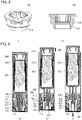
- FIG. 6 illustrates operations of the retractable container according to one embodiment of the present invention.
- FIG. 6A illustrates a locked state of the body part 200.
- the raising of the elevation part 300 may be limited.
- the pressing part 400 may be disposed so as not to be separated from the lower portion of the cover part 100. Further, as long as no external force is applied to the pressing part 400 as the elastic part 600 applies an elastic force toward the elevation part 300, the catching boss 322 is supported by the first catching step 422, and thus the rising limiting state may be maintained.
- the locked state the body part 200 is completely accommodated inside the cover part 100 and thus may not protrude upward from the cover part 100.
- the present invention is not limited thereto, and according to embodiments, the locked state may include a state in which the body part 200 protrudes upward from the cover part 100 within a predetermined range.
- FIG. 6B illustrates a transition state in which the body part 200 is changed from the locked state to the pop-up state by pressing the pressing part 400.
- the pressing part 400 when the pressing part 400 is raised, the elastic piece 421 is bent outward along the guide surface 510, the catching step 422 is moved from the catching boss 322 in a lateral direction as the elastic piece 421 widens to the outside, and thus the catching boss 322 may be separated from the first catching step 422.
- the raising limitation of the elevation part 300 when the raising limitation of the elevation part 300 is released, the elevation part 300 is raised by the elastic force of the elastic part 600, the body part 200 is pushed upward, and thus one end of the body part 200 may protrude while moving toward the upper side of the cover part 100.
- the elevation part 300 may be pressed and raised only until the upper end of the inner support 414 is in contact with a lower portion of the second limitation boss 710, and thus a raising range of the pressing part 400 may be limited.
- FIG. 6C illustrates the pop-up state of the body part 200.
- the elevation part 300 may be raised by the pressing until the catching boss 322 separated from the first catching step 422 is seated on the second catching step 520 of the guide part 500, and when the catching boss 322 is seated on the second catching step 520 of the guide part 500, the raising of the elevation part 300 is completed.
- a current state is changed to the pop-up state in which at least a portion of the body part 200 protrudes upward from the cover part 100 by a predetermined height, and thus the user may grip the protruding body part 200 to extract the body part 200 from the cover part 100.
- the elastic piece 421 that is bent outward along the guide surface 510 may return to an original state thereof while being gathered inward again by the elastic restoring force.
- the pressing part 400 may be lowered. In this case, the pressing part 400 may be lowered until the first limitation boss 424 comes into contact with the second limitation boss 710 and thus may return to an original location thereof before the button part 410 is raised.
- the catching boss 322 is seated on the first catching step 422 again, and thus the current state may be changed to the locked state.
- the user may change the body part 200 to the locked state or the pop-up state through a simple pressing operation on the pressing part 400 or the body part 200, and thus convenience of use can be increased.
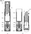
- FIG. 7 illustrates an example of use of the retractable container according to one embodiment of the present invention.
- the user may press the pressing part 400 to change the body part 200 in the locked state to the pop-up state, and when the one end of the body part 200 protrudes upward from the cover part 100 by a predetermined height as the body part 200 is changed to the pop-up state, the user may grip the one end of the body part 200, pull the one end of the body part 200 upward, and extract the body part 200 from the cover part 100.
- the user may expose the lipstick L to the outside through operation of the body part 200 and use the lipstick L. Thereafter, when the use of the lipstick L is completed, the user may insert the body part 200 into an open upper end of the cover part 100, press the body part 200 downward, and change the body part 200 to the locked state.
- the coupling between the components has been described as the coupling between the bosses and the grooves or the coupling between the bosses.
- this is illustrative, and various coupling methods can be applied according to the embodiments.
- the bosses and the grooves may be switched with each other or screw coupling may be applied.
Landscapes
- Engineering & Computer Science (AREA)
- Mechanical Engineering (AREA)
- Containers And Packaging Bodies Having A Special Means To Remove Contents (AREA)
- Closures For Containers (AREA)
Abstract
Description
- The present invention relates to a retractable container, and more particularly, to a retractable container of which a body part in which contents are accommodated may be extracted from or retracted into a cover part through a pressing operation on a pressing part.
- In general, in lipsticks, stick cosmetics used for women's lip makeup, such as rouge, are extracted from or retracted into a cylindrical container. When lipsticks are used, the stick cosmetics are extracted from the container, and when the lipsticks are completely used, the stick cosmetics are retracted into the container and may be stored without being exposed to the outside.
- In a lipstick container according to the related art, after a lid is opened, a rotating body provided at a lower portion of the container is rotated, and thus a solid stick cosmetic may be elevated to the outside of the container. For example, when a user wants to use the lipstick, first, the lid of the container is opened, the rotating body is rotated in one direction, and thus the stick cosmetic is elevated to protrude to the outside, and after the lipstick is used, the rotating body is rotated in a direction opposite to the one direction, and the stick cosmetic is lowered and is thus accommodated in the container.
- However, since the lipstick container according to the related art is configured so that anyone may easily open the lid, the lipstick is damaged and wasted by children having low thinking ability. In addition, a malfunction occurs in which the lid is opened unintentionally by the user, and thus the lipstick is extracted. Accordingly, the lipstick is extracted while being carried or unintentionally by the user, and thus the lipstick is damaged and wasted, and items carried together and bags for carrying are contaminated.
- The present invention is directed to providing a retractable container of which a body part in which contents are accommodated may be extracted from or retracted into a cover part through a pressing operation on a pressing part.
- The technical aspects of the present invention are not limited to the aspects described above, and those skilled in the art will clearly understand other technical aspects not described from the following descriptions.
- According to one embodiment of the present invention, a retractable container is provided. One aspect of the present invention provides a retractable container including a cover part of which both ends are open, a body part which is disposed in an inner upper portion of the cover part and in which a content is accommodated, an elevation part that is disposed at a lower end of the body part, is elevated inside the cover part, and has a catching boss for determining a seating location, a pressing part which is disposed below the elevation part, is elevated inside the cover part according to pressing of a user, and has an elastic piece, and a guide part which is fixedly disposed on an upper side of the pressing part and has a guide surface in contact with an upper end of the elastic piece, wherein, when the catching boss is seated on a first catching step formed on the elastic piece, raising of the elevation part and the body part is limited, and when the pressing part is raised, the elastic piece is bent along the guide surface, the catching boss is separated from the first catching step, the elevation part is raised, and thus at least a portion of the body part protrudes from the cover part.
- When the pressing is removed, outward bending of the elastic piece may be released by a restoring force of the elastic piece, and thus the pressing part may be lowered to return to an original location thereof.
- As the catching boss separated from the first catching step is seated on a second catching step formed on the guide part, the raising of the elevation part may be limited, and separation of the elevation part may be prevented.
- The retractable container may further include an elastic part which is disposed below the elevation part and generates an elastic force toward the elevation part so that the elevation part is raised when the catching boss is separated from the first catching step.
- An upper side of the first catching step may be formed as an inclined surface corresponding to the catching boss, and when the elevation part is lowered, the catching boss may be seated on the first catching step while moving to a lower side of the first catching step along the inclined surface.
- The retractable container may further include a support part which is fixedly disposed inside the cover part, has a second limitation boss in contact with a first limitation boss formed in the elastic piece when the pressing part is lowered, limits a lowering range of the pressing part, and prevents separation of the pressing part.
- When the pressing part is raised, the first limitation boss may limit a raising range of the pressing part while in contact with the pressing part.
- The pressing part may be provided with a support tube formed to extend toward the elevation part to guide elevation of the elevation part.
- The elevation part may include an accommodation part in which the body part is accommodated, a first extension part that extends downward from a bottom surface of the accommodation part and is provided with the catching boss, and a second extension part that extends downward from the bottom surface of the accommodation part to be spaced apart from an inner surface of the first extension part, and the support tube may be inserted between the first extension part and the second extension part.
- When the catching boss is seated on the first catching step, an upper end of the guide part may be in contact with a bottom surface of the elevation part to limit lowering of the elevation part.
- According to the present invention, a body part in which contents are accommodated can be changed between a locked state and a pop-up state while being extracted from or retracted into a cover part, and thus intuitive and convenient usability can be provided.
- Further, according to the present invention, a structure is designed in which the body part protrudes upward from the cover part only when a pressing part provided at one end of the cover part is pressed, and thus the contents can be prevented from being exposed to the outside unintentionally by a user.
- Further, according to the present invention, when the pressing on the pressing part is released, the pressing part is lowered by an elastic restoring force of an elastic piece to return to an original location thereof, and thus convenience in use can be improved.
- A brief description of each drawing is provided to fully understand the drawings cited in detailed description of the present invention.
-
FIG. 1 is a perspective view illustrating a retractable container according to one embodiment of the present invention. -
FIG. 2 is an exploded perspective view illustrating the retractable container according to one embodiment of the present invention. -
FIG. 3 is a cross-sectional view illustrating the retractable container according to one embodiment of the present invention. -
FIG. 4 illustrates a locking part of the retractable container according to one embodiment of the present invention. -
FIG. 5 illustrates a guide part of the retractable container according to one embodiment of the present invention. -
FIG. 6 illustrates operations of the retractable container according to one embodiment of the present invention. -
FIG. 7 illustrates an example of use of the retractable container according to one embodiment of the present invention. - Hereinafter, exemplary embodiments of the present invention will be described in detail with reference to content described in the accompanying drawings. The same reference numerals or symbols presented in each drawing indicate parts or components that perform substantially the same function. Hereinafter, for convenience of description, the up, down, left, and right directions are based on the drawings, and the scope of the present invention is not necessarily limited to the corresponding directions.
- Terms including ordinal numbers such as "first" and "second" may be used to describe various components, but the components are not limited by the terms. The terms are used only for the purpose of distinguishing one component from another component. For example, without departing from the scope of the present invention, a first component may be referred to as a second component, and similarly, a second component may be referred to as a first component. The term "and/or" includes any one item or a combination of a plurality of related items.
- Terms used in the present specification are used only to describe embodiments and are not intended to limit and/or restrict the present invention. Singular expressions include plural expressions unless clearly otherwise indicated in the context. It should be understood in the present specification that terms such as "include" or "have" are intended to indicate that there are features, numbers, steps, operations, components, parts, or combinations thereof that are described in the specification and do not exclude in advance the possibility of the presence or addition of one or more other features, numbers, steps, operations, components, parts, or combinations thereof.
- Throughout the specification, when a first part is connected to a second part, this includes not only a case in which the first part is directly connected to the second part but also a case in which the first part is indirectly connected to the second part with a third configuration therebetween. Further, when a part includes a component, this means that another component is not excluded but may be further included unless otherwise stated.
-
FIG. 1 is a perspective view illustrating a retractable container according to one embodiment of the present invention,FIG. 2 is an exploded perspective view illustrating the retractable container according to one embodiment of the present invention,FIG. 3 is a cross-sectional view illustrating the retractable container according to one embodiment of the present invention,FIG. 4 illustrates a locking part of the retractable container according to one embodiment of the present invention, andFIG. 5 illustrates a guide part of the retractable container according to one embodiment of the present invention. - Referring to
FIGS. 1 to 5 , aretractable container 1000 may include acover part 100, abody part 200, anelevation part 300, apressing part 400, aguide part 500, anelastic part 600, and asupport part 700. - The
cover part 100 is formed in an up-down longitudinal direction, both ends thereof are open, and thus an accommodation space may be formed inside thecover part 100. Some components of theretractable container 1000, for example, thebody part 200, theelevation part 300, thepressing part 400, theguide part 500, theelastic part 600, thesupport part 700, and the like may be provided to be fixed or movable in an up-down direction inside thecover part 100. - The
body part 200 may be retracted or extracted through an open upper end of thecover part 100, and components for allowing thebody part 200 to protrude upward, for example, theelevation part 300, thepressing part 400, theguide part 500, theelastic part 600, thesupport part 700, and the like, may be arranged at an open lower end of thecover part 100. - The
body part 200 contains contents therein, is disposed on an inner upper side of thecover part 100, and is separated from theretractable container 1000 by operation of a user, and the user may use the contents through thebody part 200. - A relative location between the
cover part 100 and thebody part 200 according to extraction or retraction of thebody part 200 may be a criterion for distinguishing a locked state and a pop-up state of thebody part 200. In detail, a state in which thebody part 200 is disposed inside thecover part 100, the elevation of theelevation part 300 is fixed, and thus the extraction of thebody part 200 is difficult may be the locked state. Further, a state in which at least a portion of thebody part 200 protrudes to the outside of thecover part 100 by the elevation of theelevation part 300, and thus the user may grip theprotruding body part 200 to separate thebody part 200, may be the pop-up state. - The contents accommodated in the
body part 200 may be a solid cosmetic. For example, the cosmetic may be a lipstick, a lip balm, or the like. In this case, thebody part 200 may independently form a cosmetic such as a lipstick or a lip balm. However, the present invention is not limited thereto and may include various solid or semi-solid cosmetics according to the embodiments to which the present invention is applied. Further, according to the embodiments, the contents may include a medicine. - When separated from the
cover part 100, thebody part 200 may be a cosmetic that may be used independently. For example, thebody part 200 may be configured as a lipstick container having a structure in which exposure of the contents is adjusted while the contents are elevated by a rotation operation of the user. For example, thebody part 200 may include a holder in which the contents are mounted and a guide boss is formed, a rotating body rotated by the user, a protective tube having a spiral groove formed therein through which the guide boss moves, and an elevation guide part having a vertical groove formed therein to guide elevation of the guide boss. Accordingly, the exposure of the contents may be adjusted while the holder is elevated inside the protective tube by a rotation operation of the rotating body. However, the above configuration of thebody part 200 is illustrative, and the structure of thebody part 200 is not limited thereto and may be applied to various cosmetics. - The
elevation part 300 may be disposed below thebody part 200 and may be elevated inside thecover part 100. The extraction or retraction of thebody part 200 from or into thecover part 100 may be adjusted through the elevation of theelevation part 300. Theelevation part 300 may include anaccommodation part 310, afirst extension part 320, and asecond extension part 330. - The
accommodation part 310 is intended to accommodate thebody part 200 and has an open upper end, and at least a portion of thebody part 200 may be accommodated inside theaccommodation part 310. In detail, theaccommodation part 310 is formed in the form of a tube extending upward by a predetermined length to correspond to thebody part 200, and at least a portion of an outer surface of thebody part 200 may be accommodated in theaccommodation part 310 while in close contact with an inner surface of theaccommodation part 310. According to the embodiments, a close contact boss may be formed on the inner surface of theaccommodation part 310 so that thebody part 200 is in close contact with the inside of theaccommodation part 310. Additionally, an outer surface of theaccommodation part 310 may be in close contact with an inner surface of thecover part 100. This may prevent thebody part 200 from being easily separated from theaccommodation part 310 in a state in which thebody part 200 is accommodated in theaccommodation part 310 because thebody part 200 is more closely and firmly in close contact with the inside of theaccommodation part 310. However, this is illustrative, and various configurations may be applied according to the embodiments to which the present invention is applied. For example, theaccommodation part 310 is not formed to extend long toward the upper side but may have a dish shape or a plate shape. Further, theaccommodation part 310 may be configured as at least one leg extending toward thebody part 200. - The
first extension part 320 may be formed to extend downward from a bottom surface of theaccommodation part 310, and a catchingboss 322 may be formed to protrude outward from a lower end portion of thefirst extension part 320. The catchingboss 322 may determine a location of theelevation part 300. In detail, the catchingboss 322 may control the elevation of theelevation part 300 while seated on or separated from a first catchingstep 422 or asecond catching step 520 of thepressing part 400. To facilitate catching matching, at least a portion of a lower portion of thefirst extension part 320 in which the catchingboss 322 is formed may be cut and may be implemented to be elastically deformable while bent outward or inward. - The
second extension part 330 may be formed to extend downward from the bottom surface of theaccommodation part 310. In this case, thesecond extension part 330 may be spaced apart from an inner surface of thefirst extension part 320, and at least a portion of the pressing part 400 (in particular, asupport tube 425 of a locking part 420) may be inserted into a separation space between an outer surface of thesecond extension part 330 and the inner surface of thefirst extension part 320. - In one embodiment, an
auxiliary boss 332 may be formed to protrude outward from a lower end of thesecond extension part 330. When theelevation part 300 is elevated, theauxiliary boss 332 may be elevated while in contact with an inner surface of thesupport tube 425. Further, as theauxiliary boss 332 is supported by a lockingstep 426 of thesupport tube 425, raising of theelevation part 300 may be limited and/or theelevation part 300 may be prevented from being separated from thepressing part 400. - The
pressing part 400 may be disposed below theelevation part 300 and may be elevated inside thecover part 100 according to pressing of the user. When an external force is applied, theelevation part 300 may be raised while thepressing part 400 is raised. When the external force is removed, thepressing part 400 may be lowered to return to an original location thereof. The elevation of thepressing part 400 causes the elevation of theelevation part 300 so that thebody part 200 may be extracted from or retracted into thecover part 100. To this end, thepressing part 400 may include abutton part 410 and the lockingpart 420. - The
button part 410 may be disposed inside a lower portion of thecover part 100 and may receive an external force from the user through a pressing operation on anapplication surface 412 exposed to the outside of thecover part 100. Aninner support 414 may be formed on an upper side of theapplication surface 412. Coupling bosses may be formed along a circumference of theinner support 414, and coupling grooves may be formed at a lower end of the lockingpart 420 to correspond thereto. Through fitting between the coupling bosses and the coupling grooves, thebutton part 410 and the lockingpart 420 may be coupled to each other to be integrally elevated. Anouter support 416 may be formed to protrude to be spaced outward apart from theinner support 414. Theouter support 416 may be in close contact with the inner surface of thecover part 100. Further, a lower end portion of thesupport part 700 may be retracted into or extracted from a separation space between theinner support 414 and theouter support 416 according to the elevation of thepressing part 400. - The locking
part 420 may be coupled to an upper portion of thebutton part 410 through theinner support 414 and may adjust the elevation of theelevation part 300 in conjunction with theelevation part 300 and theguide part 500. To this end, anelastic piece 421 that may be elastically deformed according to the elevation of thepressing part 400 may be formed in the lockingpart 420, and the first catchingstep 422 may be formed on an inner surface of theelastic piece 421. Theelastic piece 421 may be formed outside the lockingpart 420 in an up-down direction, and at least a portion of theelastic piece 421 may be cut for lateral bending and recovery. - When the catching
boss 322 is seated on the first catchingstep 422, the elevation of theelevation part 300 may be limited, and accordingly, raising of thebody part 200 may also be limited. In this case, when thepressing part 400 is raised, the catchingboss 322 may be separated from the first catchingstep 422 while theelastic piece 421 is bent outward by theguide part 500. Due to the separation, theelevation part 300 may be raised. Thereafter, when the pressing is removed, as the outward bending of theelastic piece 421 is released by an elastic restoring force of theelastic piece 421, thepressing part 400 may be lowered. - An upper side of the first catching
step 422 may be formed as aninclined surface 423 corresponding to the catchingboss 322. In detail, an upper region of the first catchingstep 422 may be formed as theinclined surface 423 inclined outward toward the upper side, and the catchingboss 322 may be seated on the first catchingstep 422 while moving to the lower side of the first catchingstep 422 along theinclined surface 423. - A
first limitation boss 424 may be formed on an outer surface of theelastic piece 421. Thefirst limitation boss 424 may limit downward movement of thepressing part 400 and prevent the separation of thepressing part 400 while in contact with asecond limitation boss 710 of thesupport part 700. - The
support tube 425 that extends toward theelevation part 300 and guides theelevation part 300 so that theelevation part 300 is stably elevated may be provided inside the lockingpart 420. Thesupport tube 425 may extend upward from an inner lower surface of the lockingpart 420 by a predetermined length and may be formed to be spaced inward apart from theelastic piece 421. - The
support tube 425 is inserted into a separation space between thefirst extension part 320 and thesecond extension part 330 of theelevation part 300, at least a portion of thesupport tube 425 is in contact with thefirst extension part 320 and thesecond extension part 330, and thus theelevation part 300 may be stably elevated without shaking in a left-right direction while being elevated. - The locking
step 426 may be formed on the inner surface of thesupport tube 425. When theelevation part 300 is raised, the upward movement of theelevation part 300 may be limited while theauxiliary boss 332 of thesecond extension part 330 is in contact with the lockingstep 426. Further, anelastic support part 427 may be formed in an upper region of thesupport tube 425 so that theelastic part 600 may be disposed. - The
guide part 500 may be fixedly disposed inside thecover part 100 and guide the elastic deformation of theelastic piece 421 when thepressing part 400 is elevated. In detail, aguide surface 510 having a predetermined inclination may be formed at a lower portion of theguide part 500. Theguide surface 510 may be formed to have an outwardly upward inclination. Thus, when theelastic piece 421 is raised, an upper end of theelastic piece 421 may be bent outward along the upwardlyinclined guide surface 510. - Further, the second catching
step 520 may be formed on an inner surface of theguide part 500. The catchingboss 322 is seated on the second catchingstep 520, and thus a raising range of theelevation part 300 may be limited, and the separation of theelevation part 300 may be prevented. - That is, when the catching
boss 322 is separated from the first catchingstep 422 due to the outward bending of theelastic piece 421, theelevation part 300 is raised by theelastic part 600. In this raising process, when the catchingboss 322 of theelevation part 300 is in contact with the second catchingstep 520, the raising of theelevation part 300 is finished, and theelevation part 300 may be prevented from being separated from thecover part 100 by being separated to the outside of theguide part 500 due to catching. - The
elastic part 600 may generate an elastic force toward theelevation part 300 so that theelevation part 300 is raised. In detail, when the catchingboss 322 is seated on the first catchingstep 422, theelastic part 600 may be compressed to exhibit the elastic force toward theelevation part 300. Despite the elastic force, the raising of theelevation part 300 is limited by the catchingboss 322 and the first catchingstep 422. In this case, when the catchingboss 322 is separated from the first catchingstep 422, the elastic force of theelastic part 600 is applied toward theelevation part 300, and thus theelevation part 300 may be raised. Theelastic part 600 may be implemented as any of various members which may exhibit an elastic force, such as a spring. - The
elastic part 600 may be disposed between theelevation part 300 and thepressing part 400. In detail, a lower end of theelastic part 600 may be disposed in theelastic support part 427 formed above thesupport tube 425 of the lockingpart 420. The upper end of theelastic part 600 may be disposed on the bottom surface of theaccommodation part 310 of theelevation part 300. Theelastic part 600 may be supported by the inner surface of thefirst extension part 320 on the outside and supported by an outer surface of thesupport tube 425 on the inside. Thus, theelastic part 600 may be stably compressed or tensioned according to the elevation of theelevation part 300 with respect to thepressing part 400. - The
support part 700 may be fixedly disposed inside thecover part 100, limit a lowering range of thepressing part 400, and prevent the separation of thepressing part 400. - In detail, coupling bosses may be formed on an outer surface of the
support part 700 along a circumference thereof, and coupling grooves may be formed in the inner surface of thecover part 100 to correspond thereto. As the coupling bosses of thesupport part 700 are fitted in the coupling grooves of thecover part 100, thesupport part 700 may be coupled to the inside of thecover part 100. Further, coupling grooves may be formed in an upper inner surface of thesupport part 700 along a circumference thereof, and coupling bosses may be formed on an outer surface of theguide part 500 to correspond thereto. As the coupling bosses of theguide part 500 are fitted into the coupling grooves of thesupport part 700, theguide part 500 may be coupled to thesupport part 700 and thecover part 100. - The locking
part 420 may be elevated inside thesupport part 700, and in this case, thesupport part 700 may limit the raising range and the lowering range of the lockingpart 420. To this end, thesecond limitation boss 710 may be formed on an inner surface of thesupport part 700. - In detail, when the
elastic piece 421 is lowered, thesecond limitation boss 710 supports thefirst limitation boss 424, and thus theelastic piece 421 may be prevented from being lowered and thepressing part 400 may be prevented from being separated from thecover part 100. Further, when thepressing part 400 is raised, an upper end of theinner support 414 is supported by thesecond limitation boss 710, and thus the raising may be limited. -
FIG. 6 illustrates operations of the retractable container according to one embodiment of the present invention. -
FIG. 6A illustrates a locked state of thebody part 200. In the locked state, as the catchingboss 322 is seated on the first catchingstep 422, the raising of theelevation part 300 may be limited. In this case, as thefirst limitation boss 424 formed outside theelastic piece 421 is seated and supported on an upper portion of thesecond limitation boss 710 of thesupport part 700, thepressing part 400 may be disposed so as not to be separated from the lower portion of thecover part 100. Further, as long as no external force is applied to thepressing part 400 as theelastic part 600 applies an elastic force toward theelevation part 300, the catchingboss 322 is supported by the first catchingstep 422, and thus the rising limiting state may be maintained. - In the locked state, the
body part 200 is completely accommodated inside thecover part 100 and thus may not protrude upward from thecover part 100. However, the present invention is not limited thereto, and according to embodiments, the locked state may include a state in which thebody part 200 protrudes upward from thecover part 100 within a predetermined range. -
FIG. 6B illustrates a transition state in which thebody part 200 is changed from the locked state to the pop-up state by pressing thepressing part 400. When thepressing part 400 is pressed in the locked state, as thepressing part 400 is raised, the catchingboss 322 is separated from the first catchingstep 422, and thus theelevation part 300 may be raised by theelastic part 600. - In detail, when the
pressing part 400 is raised, theelastic piece 421 is bent outward along theguide surface 510, the catchingstep 422 is moved from the catchingboss 322 in a lateral direction as theelastic piece 421 widens to the outside, and thus the catchingboss 322 may be separated from the first catchingstep 422. In this way, when the raising limitation of theelevation part 300 is released, theelevation part 300 is raised by the elastic force of theelastic part 600, thebody part 200 is pushed upward, and thus one end of thebody part 200 may protrude while moving toward the upper side of thecover part 100. In this case, theelevation part 300 may be pressed and raised only until the upper end of theinner support 414 is in contact with a lower portion of thesecond limitation boss 710, and thus a raising range of thepressing part 400 may be limited. -
FIG. 6C illustrates the pop-up state of thebody part 200. Theelevation part 300 may be raised by the pressing until the catchingboss 322 separated from the first catchingstep 422 is seated on the second catchingstep 520 of theguide part 500, and when the catchingboss 322 is seated on the second catchingstep 520 of theguide part 500, the raising of theelevation part 300 is completed. - In this way, a current state is changed to the pop-up state in which at least a portion of the
body part 200 protrudes upward from thecover part 100 by a predetermined height, and thus the user may grip the protrudingbody part 200 to extract thebody part 200 from thecover part 100. - In this state, when the pressing of the pressing part 40 is released, the
elastic piece 421 that is bent outward along theguide surface 510 may return to an original state thereof while being gathered inward again by the elastic restoring force. As theelastic piece 421 is lowered along theguide surface 510 while theelastic piece 421 returns to an original state thereof, thepressing part 400 may be lowered. In this case, thepressing part 400 may be lowered until thefirst limitation boss 424 comes into contact with thesecond limitation boss 710 and thus may return to an original location thereof before thebutton part 410 is raised. - Meanwhile, in the pop-up state of the
body part 200, when thebody part 200 is pressed downward to lower theelevation part 300, the catchingboss 322 is seated on the first catchingstep 422 again, and thus the current state may be changed to the locked state. The user may change thebody part 200 to the locked state or the pop-up state through a simple pressing operation on thepressing part 400 or thebody part 200, and thus convenience of use can be increased. -
FIG. 7 illustrates an example of use of the retractable container according to one embodiment of the present invention. - Referring to
FIG. 7A , in order for the user to use a lipstick L accommodated in thebody part 200, the user may press thepressing part 400 to change thebody part 200 in the locked state to the pop-up state, and when the one end of thebody part 200 protrudes upward from thecover part 100 by a predetermined height as thebody part 200 is changed to the pop-up state, the user may grip the one end of thebody part 200, pull the one end of thebody part 200 upward, and extract thebody part 200 from thecover part 100. - Subsequently, referring to
FIG. 7B , in a state in which thebody part 200 is extracted from thecover part 100, the user may expose the lipstick L to the outside through operation of thebody part 200 and use the lipstick L. Thereafter, when the use of the lipstick L is completed, the user may insert thebody part 200 into an open upper end of thecover part 100, press thebody part 200 downward, and change thebody part 200 to the locked state. - Hereinabove, the coupling between the components has been described as the coupling between the bosses and the grooves or the coupling between the bosses. However, this is illustrative, and various coupling methods can be applied according to the embodiments. For example, the bosses and the grooves may be switched with each other or screw coupling may be applied.
- Although the embodiments have been described above with reference to the limited embodiments and the limited drawings, various modifications and changes may be made based on the above description by those skilled in the art. Further, respective embodiments may be operated in combination with each other as needed. Therefore, other implementations, other embodiments, and equivalents to the appended claims also belong to the scope of the appended claims.
Claims (10)
- A retractable container comprising:a cover part of which both ends are open;a body part which is disposed in an inner upper portion of the cover part and in which a content is accommodated;an elevation part that is disposed at a lower end of the body part, is elevated inside the cover part, and has a catching boss for determining a seating location;a pressing part which is disposed below the elevation part, is elevated inside the cover part according to pressing of a user, and has an elastic piece; anda guide part which is fixedly disposed on an upper side of the pressing part and has a guide surface in contact with an upper end of the elastic piece,wherein, when the catching boss is seated on a first catching step formed on the elastic piece, raising of the elevation part and the body part is limited, andwhen the pressing part is raised, the elastic piece is bent along the guide surface, the catching boss is separated from the first catching step, the elevation part is raised, and thus at least a portion of the body part protrudes from the cover part.
- The retractable container of claim 1, wherein, when the pressing is removed, outward bending of the elastic piece is released by a restoring force of the elastic piece, and thus the pressing part is lowered to return to an original location thereof.
- The retractable container of claim 1, wherein, as the catching boss separated from the first catching step is seated on a second catching step formed on the guide part, the raising of the elevation part is limited, and separation of the elevation part is prevented.
- The retractable container of claim 1, further comprising an elastic part which is disposed below the elevation part and generates an elastic force toward the elevation part so that the elevation part is raised when the catching boss is separated from the first catching step.
- The retractable container of claim 1, wherein an upper side of the first catching step is formed as an inclined surface corresponding to the catching boss, and when the elevation part is lowered, the catching boss is seated on the first catching step while moving to a lower side of the first catching step along the inclined surface.
- The retractable container of claim 1, further comprising a support part which is fixedly disposed inside the cover part, has a second limitation boss in contact with a first limitation boss formed in the elastic piece when the pressing part is lowered, limits a lowering range of the pressing part, and prevents separation of the pressing part.
- The retractable container of claim 6, wherein, when the pressing part is raised, the first limitation boss limits a raising range of the pressing part while in contact with the pressing part.
- The retractable container of claim 1, wherein the pressing part is provided with a support tube formed to extend toward the elevation part to guide elevation of the elevation part.
- The retractable container of claim 8, wherein the elevation part includes:an accommodation part in which the body part is accommodated;a first extension part that extends downward from a bottom surface of the accommodation part and is provided with the catching boss; anda second extension part that extends downward from the bottom surface of the accommodation part to be spaced apart from an inner surface of the first extension part, andthe support tube is inserted between the first extension part and the second extension part.
- The retractable container of claim 1, wherein, when the catching boss is seated on the first catching step, an upper end of the guide part is in contact with a bottom surface of the elevation part to limit lowering of the elevation part.
Applications Claiming Priority (2)
| Application Number | Priority Date | Filing Date | Title |
|---|---|---|---|
| KR1020190135351A KR102282237B1 (en) | 2019-10-29 | 2019-10-29 | Retractable container |
| PCT/KR2020/012932 WO2021085863A1 (en) | 2019-10-29 | 2020-09-24 | Retractable container |
Publications (2)
| Publication Number | Publication Date |
|---|---|
| EP4052607A1 true EP4052607A1 (en) | 2022-09-07 |
| EP4052607A4 EP4052607A4 (en) | 2023-12-06 |
Family
ID=75714527
Family Applications (1)
| Application Number | Title | Priority Date | Filing Date |
|---|---|---|---|
| EP20883231.1A Withdrawn EP4052607A4 (en) | 2019-10-29 | 2020-09-24 | RETRACTABLE CONTAINER |
Country Status (6)
| Country | Link |
|---|---|
| US (1) | US12053076B2 (en) |
| EP (1) | EP4052607A4 (en) |
| JP (1) | JP7407921B2 (en) |
| KR (1) | KR102282237B1 (en) |
| CN (1) | CN114667083B (en) |
| WO (1) | WO2021085863A1 (en) |
Families Citing this family (7)
| Publication number | Priority date | Publication date | Assignee | Title |
|---|---|---|---|---|
| FR3077188B1 (en) * | 2018-01-29 | 2020-01-10 | L'oreal | DEVICE FOR SUPPORTING A COSMETIC ARTICLE |
| USD1022329S1 (en) * | 2020-09-14 | 2024-04-09 | David F. Tita | Combination football-shaped container and lip balm |
| KR102485547B1 (en) * | 2021-05-14 | 2023-01-05 | 황성민 | Cup holder device for motors |
| FR3129576B1 (en) * | 2021-11-29 | 2024-04-12 | Dior Christian Parfums | Device for packaging a product |
| CN116530794B (en) * | 2023-05-26 | 2025-10-17 | 明门(中国)幼童用品有限公司 | Telescopic stand pipe assembly and baby sleeping basket |
| KR20250172198A (en) | 2024-05-31 | 2025-12-09 | (주)장업시스템 | Stick-type cosmetic container protection cas |
| JP7831730B1 (en) * | 2024-09-05 | 2026-03-17 | サムファ カンパニー リミテッド | Lifting mechanism for stick-type products and stick-type container equipped therewith |
Family Cites Families (23)
| Publication number | Priority date | Publication date | Assignee | Title |
|---|---|---|---|---|
| JPH0525536Y2 (en) * | 1987-04-06 | 1993-06-28 | ||
| CA2607266C (en) | 2005-05-10 | 2011-08-09 | Chanel Parfums Beaute | Container for a liquid, solid, pasty or powder cosmetic having a retractable dispensing element |
| KR200448156Y1 (en) * | 2007-11-08 | 2010-03-18 | (주)아모레퍼시픽 | Lipsticks that can be used |
| FR2942116B1 (en) * | 2009-02-17 | 2013-08-09 | Oreal | DEVICE FOR SUPPORTING A COSMETIC ARTICLE AND ASSOCIATED METHOD |
| FR2943897B1 (en) * | 2009-04-03 | 2014-06-13 | Dior Christian Parfums | PRODUCT DISTRIBUTOR. |
| KR200459451Y1 (en) * | 2009-10-13 | 2012-03-27 | 주식회사 태성산업 | Lipstick Container |
| FR2954058B1 (en) * | 2009-12-23 | 2012-03-16 | Chanel Parfums Beaute | CONTAINER OF COSMETIC OR HYGIENIC PRODUCT IN GRAPE WITH REMOVABLE APPLICATION ELEMENT |
| CN201806132U (en) * | 2010-08-13 | 2011-04-27 | 常州圣美包装制品有限公司 | Bouncer mechanism |
| KR101201734B1 (en) * | 2011-02-24 | 2012-11-15 | (주)연우 | Lipstick case |
| KR101199773B1 (en) | 2011-02-24 | 2012-11-09 | (주)연우 | Lipstick case |
| KR200479856Y1 (en) * | 2011-10-14 | 2016-03-14 | 펌텍코리아 (주) | Cosmetic container |
| KR101602925B1 (en) * | 2015-06-24 | 2016-03-14 | 주식회사 리치코스 | Button-type lipstick container |
| KR20170067564A (en) * | 2015-12-08 | 2017-06-16 | 쓰리애플즈코스메틱스 주식회사 | Lipstick container assembly |
| CN205612019U (en) * | 2016-03-24 | 2016-10-05 | 浙江阿克希龙舜华铝塑业有限公司 | There is not type of glue lipstick pipe median bundle core |
| CN105852386B (en) * | 2016-06-21 | 2018-03-13 | 洽兴包装工业(中国)有限公司 | Push type cosmetic cover body structure |
| KR101707455B1 (en) * | 2016-11-11 | 2017-02-17 | 주식회사 씨티케이코스메틱스 | A cosmetics container which cap is operated to be opened and closed in one-touch way |
| KR200487954Y1 (en) * | 2017-03-20 | 2018-11-26 | 주식회사 엘지생활건강 | A cosmetic device |
| KR101933888B1 (en) | 2017-07-03 | 2019-01-02 | 펌텍코리아(주) | Stick typed cosmetic container having side button |
| KR101803794B1 (en) * | 2017-10-25 | 2017-12-01 | 주식회사 네스필러피케이지 | Cosmetic Bottle with a opening and Shutting structure by button |
| FR3077188B1 (en) | 2018-01-29 | 2020-01-10 | L'oreal | DEVICE FOR SUPPORTING A COSMETIC ARTICLE |
| CN208228579U (en) * | 2018-03-15 | 2018-12-14 | 汕头市森艺塑胶有限公司 | A kind of novel pressing bullet modus ponens lipstick tube |
| KR101995880B1 (en) * | 2019-04-19 | 2019-10-01 | 이지영 | The stick type cosmetics case |
| KR102622172B1 (en) * | 2019-09-20 | 2024-01-08 | (주)아모레퍼시픽 | Cosmetic stick case which makeup stick is pulled out by magnetic force |
-
2019
- 2019-10-29 KR KR1020190135351A patent/KR102282237B1/en active Active
-
2020
- 2020-09-24 US US17/773,218 patent/US12053076B2/en active Active
- 2020-09-24 JP JP2022523633A patent/JP7407921B2/en active Active
- 2020-09-24 WO PCT/KR2020/012932 patent/WO2021085863A1/en not_active Ceased
- 2020-09-24 CN CN202080076015.XA patent/CN114667083B/en active Active
- 2020-09-24 EP EP20883231.1A patent/EP4052607A4/en not_active Withdrawn
Also Published As
| Publication number | Publication date |
|---|---|
| CN114667083B (en) | 2024-05-14 |
| WO2021085863A1 (en) | 2021-05-06 |
| US12053076B2 (en) | 2024-08-06 |
| KR20210050837A (en) | 2021-05-10 |
| EP4052607A4 (en) | 2023-12-06 |
| JP7407921B2 (en) | 2024-01-04 |
| KR102282237B1 (en) | 2021-07-27 |
| CN114667083A (en) | 2022-06-24 |
| US20220386757A1 (en) | 2022-12-08 |
| JP2022553707A (en) | 2022-12-26 |
Similar Documents
| Publication | Publication Date | Title |
|---|---|---|
| US12053076B2 (en) | Retractable container | |
| CN115003191B (en) | Stick-shaped cosmetic container with light margin | |
| CN101170925B (en) | Receptacles for liquid, solid, paste or powder cosmetic products with retractable application elements | |
| CN100515266C (en) | Bar-like cosmetic delivering container | |
| NL8401180A (en) | COSMETIC POWDER BOX WITH PULL-OUT APPLIANCE AND METHOD FOR USE THEREOF. | |
| CN110799061A (en) | Stick-type cosmetic material container with side buttons | |
| KR102354088B1 (en) | Device for supporting cosmetic articles | |
| KR101625329B1 (en) | Stick-shaped cosmetic container | |
| KR102619824B1 (en) | Container | |
| KR200493596Y1 (en) | Sunstick case | |
| KR102290356B1 (en) | Retractable container | |
| KR200388883Y1 (en) | Lipstick case | |
| US20230263287A1 (en) | Refillable container | |
| KR101842886B1 (en) | Lib stick container | |
| KR20200014381A (en) | Cosmetic holder system | |
| KR20200045375A (en) | Cosmetic container | |
| RU2391033C2 (en) | Body and traffic control system for cosmetic containers | |
| KR101957853B1 (en) | Cosmetics container having touch member to be lifted and to be rotated | |
| KR101931509B1 (en) | Cosmetic case | |
| KR102272642B1 (en) | Cosmetics container with double sealing structure | |
| JPH10304930A (en) | Bar-shaped cosmetic container | |
| KR102836033B1 (en) | Container | |
| KR101986283B1 (en) | Cosmetic brush having adjustment stick | |
| KR200493058Y1 (en) | Container | |
| CN119856835A (en) | Refill unit for sun cream and refillable stick container provided with same |
Legal Events
| Date | Code | Title | Description |
|---|---|---|---|
| STAA | Information on the status of an ep patent application or granted ep patent |
Free format text: STATUS: THE INTERNATIONAL PUBLICATION HAS BEEN MADE |
|
| PUAI | Public reference made under article 153(3) epc to a published international application that has entered the european phase |
Free format text: ORIGINAL CODE: 0009012 |
|
| STAA | Information on the status of an ep patent application or granted ep patent |
Free format text: STATUS: REQUEST FOR EXAMINATION WAS MADE |
|
| 17P | Request for examination filed |
Effective date: 20220520 |
|
| AK | Designated contracting states |
Kind code of ref document: A1 Designated state(s): AL AT BE BG CH CY CZ DE DK EE ES FI FR GB GR HR HU IE IS IT LI LT LU LV MC MK MT NL NO PL PT RO RS SE SI SK SM TR |
|
| DAV | Request for validation of the european patent (deleted) | ||
| DAX | Request for extension of the european patent (deleted) | ||
| A4 | Supplementary search report drawn up and despatched |
Effective date: 20231108 |
|
| RIC1 | Information provided on ipc code assigned before grant |
Ipc: A45D 40/00 20060101ALI20231102BHEP Ipc: B65D 83/00 20060101ALI20231102BHEP Ipc: A45D 40/02 20060101ALI20231102BHEP Ipc: A45D 40/10 20060101AFI20231102BHEP |
|
| GRAP | Despatch of communication of intention to grant a patent |
Free format text: ORIGINAL CODE: EPIDOSNIGR1 |
|
| STAA | Information on the status of an ep patent application or granted ep patent |
Free format text: STATUS: GRANT OF PATENT IS INTENDED |
|
| INTG | Intention to grant announced |
Effective date: 20240709 |
|
| STAA | Information on the status of an ep patent application or granted ep patent |
Free format text: STATUS: THE APPLICATION IS DEEMED TO BE WITHDRAWN |
|
| 18D | Application deemed to be withdrawn |
Effective date: 20241112 |