EP4051876B1 - Brennkraftmaschine mit einer kurbelwellenführung - Google Patents
Brennkraftmaschine mit einer kurbelwellenführung Download PDFInfo
- Publication number
- EP4051876B1 EP4051876B1 EP20881761.9A EP20881761A EP4051876B1 EP 4051876 B1 EP4051876 B1 EP 4051876B1 EP 20881761 A EP20881761 A EP 20881761A EP 4051876 B1 EP4051876 B1 EP 4051876B1
- Authority
- EP
- European Patent Office
- Prior art keywords
- engine
- internal combustion
- combustion engine
- piston
- connecting rod
- Prior art date
- Legal status (The legal status is an assumption and is not a legal conclusion. Google has not performed a legal analysis and makes no representation as to the accuracy of the status listed.)
- Active
Links
Images


Classifications
-
- F—MECHANICAL ENGINEERING; LIGHTING; HEATING; WEAPONS; BLASTING
- F01—MACHINES OR ENGINES IN GENERAL; ENGINE PLANTS IN GENERAL; STEAM ENGINES
- F01B—MACHINES OR ENGINES, IN GENERAL OR OF POSITIVE-DISPLACEMENT TYPE, e.g. STEAM ENGINES
- F01B9/00—Reciprocating-piston machines or engines characterised by connections between pistons and main shafts, not specific to groups F01B1/00 - F01B7/00
- F01B9/02—Reciprocating-piston machines or engines characterised by connections between pistons and main shafts, not specific to groups F01B1/00 - F01B7/00 with crankshaft
- F01B9/023—Reciprocating-piston machines or engines characterised by connections between pistons and main shafts, not specific to groups F01B1/00 - F01B7/00 with crankshaft of Bourke-type or Scotch yoke
-
- F—MECHANICAL ENGINEERING; LIGHTING; HEATING; WEAPONS; BLASTING
- F01—MACHINES OR ENGINES IN GENERAL; ENGINE PLANTS IN GENERAL; STEAM ENGINES
- F01B—MACHINES OR ENGINES, IN GENERAL OR OF POSITIVE-DISPLACEMENT TYPE, e.g. STEAM ENGINES
- F01B9/00—Reciprocating-piston machines or engines characterised by connections between pistons and main shafts, not specific to groups F01B1/00 - F01B7/00
- F01B9/02—Reciprocating-piston machines or engines characterised by connections between pistons and main shafts, not specific to groups F01B1/00 - F01B7/00 with crankshaft
-
- F—MECHANICAL ENGINEERING; LIGHTING; HEATING; WEAPONS; BLASTING
- F02—COMBUSTION ENGINES; HOT-GAS OR COMBUSTION-PRODUCT ENGINE PLANTS
- F02B—INTERNAL-COMBUSTION PISTON ENGINES; COMBUSTION ENGINES IN GENERAL
- F02B75/00—Other engines
- F02B75/16—Engines characterised by number of cylinders, e.g. single-cylinder engines
- F02B75/18—Multi-cylinder engines
- F02B75/24—Multi-cylinder engines with cylinders arranged oppositely relative to main shaft and of "flat" type
- F02B75/246—Multi-cylinder engines with cylinders arranged oppositely relative to main shaft and of "flat" type with only one crankshaft of the "pancake" type, e.g. pairs of connecting rods attached to common crankshaft bearing
-
- F—MECHANICAL ENGINEERING; LIGHTING; HEATING; WEAPONS; BLASTING
- F02—COMBUSTION ENGINES; HOT-GAS OR COMBUSTION-PRODUCT ENGINE PLANTS
- F02B—INTERNAL-COMBUSTION PISTON ENGINES; COMBUSTION ENGINES IN GENERAL
- F02B75/00—Other engines
- F02B75/32—Engines characterised by connections between pistons and main shafts and not specific to preceding main groups
-
- F—MECHANICAL ENGINEERING; LIGHTING; HEATING; WEAPONS; BLASTING
- F16—ENGINEERING ELEMENTS AND UNITS; GENERAL MEASURES FOR PRODUCING AND MAINTAINING EFFECTIVE FUNCTIONING OF MACHINES OR INSTALLATIONS; THERMAL INSULATION IN GENERAL
- F16C—SHAFTS; FLEXIBLE SHAFTS; ELEMENTS OR CRANKSHAFT MECHANISMS; ROTARY BODIES OTHER THAN GEARING ELEMENTS; BEARINGS
- F16C7/00—Connecting-rods or like links pivoted at both ends; Construction of connecting-rod heads
- F16C7/02—Constructions of connecting-rods with constant length
- F16C7/023—Constructions of connecting-rods with constant length for piston engines, pumps or the like
-
- F—MECHANICAL ENGINEERING; LIGHTING; HEATING; WEAPONS; BLASTING
- F16—ENGINEERING ELEMENTS AND UNITS; GENERAL MEASURES FOR PRODUCING AND MAINTAINING EFFECTIVE FUNCTIONING OF MACHINES OR INSTALLATIONS; THERMAL INSULATION IN GENERAL
- F16H—GEARING
- F16H21/00—Gearings comprising primarily only links or levers, with or without slides
- F16H21/10—Gearings comprising primarily only links or levers, with or without slides all movement being in, or parallel to, a single plane
- F16H21/16—Gearings comprising primarily only links or levers, with or without slides all movement being in, or parallel to, a single plane for interconverting rotary motion and reciprocating motion
- F16H21/18—Crank gearings; Eccentric gearings
- F16H21/36—Crank gearings; Eccentric gearings without swinging connecting-rod, e.g. with epicyclic parallel motion, slot-and-crank motion
-
- F—MECHANICAL ENGINEERING; LIGHTING; HEATING; WEAPONS; BLASTING
- F16—ENGINEERING ELEMENTS AND UNITS; GENERAL MEASURES FOR PRODUCING AND MAINTAINING EFFECTIVE FUNCTIONING OF MACHINES OR INSTALLATIONS; THERMAL INSULATION IN GENERAL
- F16C—SHAFTS; FLEXIBLE SHAFTS; ELEMENTS OR CRANKSHAFT MECHANISMS; ROTARY BODIES OTHER THAN GEARING ELEMENTS; BEARINGS
- F16C2360/00—Engines or pumps
- F16C2360/22—Internal combustion engines
Definitions
- This invention relates to an internal combustion engine. More particularly, but not exclusively, the invention relates to an internal combustion engine with piston motion characteristics leading to improved performance.
- US2007079787A1 discloses an internal combustion engine that has a piston within a cylinder and has a crankcase, defining a combustion chamber and crank volume.
- DE102007056203A1 concerns a crankshaft lubricating device for internal-combustion engine of motor vehicle.
- US2013019835A1 and US2019100295A1 relate to internal combustion engines.
- Examples of the present invention seek to avoid or at least ameliorate the disadvantages of existing internal combustion engines.
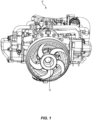
- FIGS 1 to 4 depict operation of an internal combustion engine in accordance with an example of the present invention.
- an internal combustion engine 10 including a cylinder 12, a piston 14 (also reference numeral 92 in Figure 5 ), and an output shaft 16, wherein the piston 14 is arranged for reciprocating motion within the cylinder 12, driven by combustion, and the piston 14 is coupled to the output shaft 16 by a coupling.
- the engine 10 is configured such that said reciprocating motion of the piston 14 drives rotation of the output shaft 16.
- the coupling is arranged such that the piston 14 has sinusoidal motion when plotted against rotational angle of the output shaft 16.
- the engine 10 is in the form of a scotch yoke engine, as shown in Figure 1 , and the coupling includes a slider bearing 90 (or slider block) which is able to slide along a channel formed between opposed connecting rods 86.
- the engine 10 of the example includes a pair of opposed pistons 14 which are mutually rigidly fixed such that movement of one piston in a first direction causes movement of the other piston in a second direction which is opposite to the first direction (see also pistons 92 in Figure 5 ).
- the engine 10 is arranged such that, when measured against a conventional crankshaft engine of identical bore and stroke, the motion of the piston 14 after top dead centre (“TDC") has a lower displacement, velocity and acceleration such that volumetric difference in the cylinder 12, when compared to the conventional crankshaft engine, peaks at between 10% and 20% between TDC and bottom dead centre (“BDC").
- TDC top dead centre
- BDC bottom dead centre
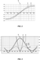
- Total Working Unit Cylinder Volume of the engine 10 is shown by line 22, whereas Total Working Unit Cylinder Volume of a conventional engine having identical bore and stroke (to engine 10) is shown by line 24.
- motion of the piston 14 is sinusoidal such that velocity of the piston 14 is greater around TDC 26 (than for a conventional engine) whereas velocity of the piston 14 is less around BDC 28 (than for a conventional engine).
- the engine 10 is arranged such that, when measured against a conventional crankshaft engine of identical bore and stroke, the motion of the piston 14 after TDC 26 has a lower acceleration such that volumetric difference in the cylinder 12 peaks at between 15% and 17% between TDC 26 and BDC 28.
- the engine 10 is arranged such that, when measured against a conventional crankshaft engine of identical bore and stroke, the motion of the piston 14 after TDC 26 has a lower acceleration such that volumetric difference in the cylinder 12 peaks at between 40 and 80 degrees of output shaft rotation after TDC 26.
- This peak may, more specifically, be between 50 and 70 degrees of output shaft rotation after TDC. Even more specifically, this peak may be between 50 and 60 degrees of output shaft rotation after TDC 26.
- the engine 10 includes a combustion chamber 30 for combustion of the charge, and the combustion chamber 30 and/or the coupling is/are arranged to achieve goal volumetric difference characteristics, when compared to a conventional crankshaft engine.
- the applicant has, advantageously, identified a method of manufacturing (and, specifically, designing) an engine 10, the method including the steps of measuring and/or modelling charge density in the cylinder 12 to obtain data; and using the data to optimise one or more parameter(s) of the engine 10 so as to increase maintenance of a gas state with a higher charge density around TDC 26.
- the method may include the step of using the data to optimise one or more parameter(s) of the engine 10, the parameter(s) including one or more of the coupling, the piston 14, the cylinder 12, the combustion chamber 30, and valves 32.
- the method may include the step of using the data to optimise one or more parameter(s) of the engine 10 so as to increase maintenance of a gas state with a higher charge density around TDC 26 to achieve improved fuel mixing.
- movement of the piston 14 in the engine 10 is sinusoidal.
- the movement of the piston 14 against crank angle over top dead centre 26 and bottom dead centre 28 are identical, as shown by the sinusoidal curve of line 22 in Figure 3 .
- crank and connecting rod mechanism of conventional engines produces unequal piston movement in the region of TDC 26 and BDC 28 (see line 24 in comparison to line 22).
- TDC 26 the piston of the conventional engine moves faster than in the engine 10 of present invention and, in the region of BDC 28, the piston of the conventional engine moves slower than in the engine 10 of the present invention.
- the difference between these two conditions depends on the length of a con rod. The shorter the con rod, the greater the differences.
- the power level for a given piston displacement is very much a function of the amount of air mass captured per cycle affecting the engine volumetric efficiency.
- Volumetric efficiency depends on several engine design parameters, namely; cam profile, valve timing, manifold tuned length, forced air induction (Turbo/Supercharging) etc. which are optimised for the pressure wave dynamics set by any given piston motion. Therefore, the processes that will be influenced by piston motion can be divided into two categories; induction process and post induction processes.
- the present invention focusses on the post induction processes ie.: compression, combustion and expansion, being influenced by the piston motion.
- the applicant has identified that it is of particular interest to note the production of NOx emissions in the combustion processes and the expansion stroke (post combustion) when the useful work is produced.
- the advantages of the engine 10 of the present invention and, in particular, the advantage of the motion of the piston 14 over that of a conventional engine we must first compare an identical volumetric efficiency and piston bore and stroke to have identical induction conditions for both the engine 10 of the present invention and a conventional engine.
- Piston velocity in this unit is independent of engine speed and hence is characteristic of piston motion over the entire speed range.
- the piston 14 of the engine 10 approaches and goes away from TDC 26 at a lower acceleration (rate of change of velocity) than the conventional piston.
- This means the engine 10 will have a lower rate of cylinder volume change around TDC 26 and therefore will help maintain a gas state with higher charge density around TDC 26.
- the applicant has identified that a higher charge density assists the flame to speed up.
- the lower piston acceleration extends over a considerable part of the gas expansion duration.
- the cylinder peak pressures are found to be lower in the engine 10 than in the conventional engine in most speeds except for the lower speeds of 1500 and 2500 r/min where the peak pressures are very similar.
- cylinder pressure during the gas expansion process i.e. after mass fraction burned has reached 1.0
- squish velocity including the geometry of the squish surfaces
- heat losses through surface influenced by combustion chamber geometry, piston-con rod connection responsible for uniformity of temperature of piston crown around the joint face, cooling water circuit, etc.
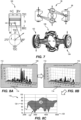
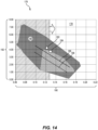
- FIG. 4 there are shown modelling results of the engine 10 according to an example of the present invention, depicting the near perfect airflow tumble as it enters and fills the cylinder 12 resulting in homogenous fuel mixing giving cleaner combustion, high torque and lower emissions.
- the piston 14 approaches and goes away from TDC 26 at a lower acceleration than the conventional piston with both engines having identical stroke and bore. This means the engine 10 will have a lower rate of cylinder volume change around TDC 26 and the applicant has identified that this helps maintain a gas state with higher charge density around TDC 26, leading to homogenous fuel mixing resulting in cleaner combustion, more engine knock resistance, high EGR tolerance, high torque and lower emissions.
- the applicant has identified that the engine 10 may be used to drive a generator in a hybrid vehicle. More specifically, the applicant has identified that the engine 10 may be used to drive a generator in a series hybrid vehicle, possibly with the engine being operated at constant rotational velocity during running of the generator which may be located in a discrete location of the vehicle, such as in the boot/trunk.
- the efficiency, balance, low vibration and quietness of the engine 10 may make the engine 10 particularly suitable to such an application.
- oil pressure is generated by an oil pump driven by the crankshaft.
- a pressure regulating device When excess oil pressure and flow is achieved by the oil pump at higher engine speeds, this excess oil is redirected by a pressure regulating device back into the suction port of the pump or back to the sump via an exhaust passage.
- the engine Normally, in a range extender engine, when the engine is at low engine speeds, the engine has low oil pressure but is also at low load. When the engine speed is increased, so too is the load and correspondingly the oil pressure and flow is also increased to a point where the pump generates excess oil that is not normally used and is redirected back to the engine sump or back to the pump suction port.
- the following invention outlines several methods of targeting lubrication to the areas of an engine that need it most and a method of using this excess oil to the advantage of the engine by redirecting this excess oil in the first case to other areas of the engine and then if the pump still has excess oil available, only then would the oil be redirected back to the suction port of the pump or to the sump.
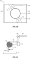
- piston sprays in engine block that are fed from excess oil from slider block.
- Slider block oil gallery aligns with spray nozzle and supplies oil to jet at the top and bottom of each stroke (jets closed in this view).
- Piston Sprays in engine block that are fed from excess oil from slider block. Slider block oil gallery aligns with spray nozzle and supplies oil to jet at the top and bottom of each stroke (top jet open in this view).
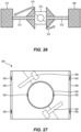
- Figure 27 shows notches in edge of bearing faces (6 shown) to allow oil to leak past the thrust face and out the side of the bearing to lubricate the sides of the bearing and the associated thrust faces. This also applies to the side of the crank flange guide faces.
- balance shaft In many traditional engines, a balance shaft is used to reduce engine vibration. These balance shafts spin at a speed relative to the engine and are driven by the crankshaft. This speed is normally twice engine speed and in the case of a 4 cylinder in-line conventional engine two balance shafts are required. These shafts act to dampen engine vibration by inducing an imbalance opposite to the engine induced vibration, normally known as second order forces.
- camshaft and balance shaft would spin in the same direction so as to minimise the differential bearing speeds between the parts.
- the Sytech engine is an engine that relies on the Scotch Yoke principle of operation in a horizontal, opposed in-line cylinder arrangement.
- these engines require very close tolerance of the two opposing cylinders within the cylinder block to ensure alignment and so as not to induce side load of the piston or over-constraint and loading of the slider block on the crankshaft. This results in very tight tolerances and manufacturing cost on the:
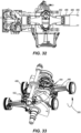
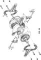
- FIG. 36 to 39 there is shown an arrangement in which the connecting rods of the internal combustion engine are formed of two like parts, each of the like parts being in the form of an identical C-claw. More specifically, there is shown an internal combustion engine, including a pair of opposed pistons, a pair of opposed cylinders, and an output shaft, wherein each of the pistons is arranged for reciprocating motion within a respective one of the cylinders, driven by combustion, and the pistons are coupled to the output shaft by a coupling such that said reciprocating motion of the pistons drives rotation of the output shaft.
- the coupling includes a connecting rod coupled to the opposed pistons, the connecting rod being formed from a pair of like parts 524, 526 fastened together, one 526 of the like parts being reversed relative to the other 524 of the like parts prior to fastening.
- the connecting rod may have side guides for guiding a slider bearing located for reciprocating movement relative to the connecting rod, and the coupling may further include a crankshaft rotatably mounted within the slider bearing.
- the Sytech engine may have an intake system 530 which promotes a cyclonic airflow in a plenum chamber so as to have an effect similar to a ram charging effect.
- an internal combustion engine including a pair of opposed pistons, a pair of opposed cylinders, and an output shaft, wherein each of the pistons is arranged for reciprocating motion within a respective one of the cylinders, driven by combustion, and the pistons are coupled to the output shaft by a coupling such that said reciprocating motion of the pistons drives rotation of the output shaft, wherein the coupling includes a connecting rod coupled to the opposed pistons, the connecting rod having side guides for guiding a slider bearing located for reciprocating movement relative to the connecting rod.
- the coupling further includes a crankshaft rotatably mounted within the slider bearing.
- the internal combustion engine includes an intake system 530 arranged to induce cyclonic airflow in a plenum chamber of the intake system.
- the firing order of the cylinders may be 1-2-4-3.
- the intake system may be arranged such that intake conduits leading to the cylinders meet at the plenum chamber and are arranged generally in a circular configuration about the plenum chamber in the firing order of the cylinders.
- the intake conduits from the plenum chamber to the cylinders may be arranged to promote free flow resulting from the cyclonic airflow in the plenum chamber.
- the intake conduits may be directed to capture flow from the cyclonic airflow in the plenum chamber.
- the intake conduits may lead tangentially from the plenum chamber so as to efficiently capture momentum of the cyclonic airflow.
- the plenum chamber may be located centrally in relation to the cylinders of the engine and this may be of particular advantage where the engine is a Scotch Yoke type engine as this may facilitate the central placement of the plenum chamber as well as the tuning of the lengths of the intake conduits.
- the intake conduits may each be of equal length.
- the invention may be used in a wide variety of applications and, in particular, as a low cost and unique solution for modern range extenders.
- the inventors have developed a new family of modern opposed piston gasoline engines based on the Scotch Yoke Crankshaft connection principle, called the SYTECH Engine.
- the engine family consists of modular 2 cylinder units that are joined together to create a family of engines. Due to the engine construction, the engine can be modularized in even numbers of cylinders, i.e, 2 cylinders, 4 cylinders, 8 cylinders etc. With this approach, common engine parts and architecture can be employed to reduce engine cost and weight.
- This paper focusses primarily on the first engine in the family, a 1.5 litre 4 cylinder engine identified as the 415 engine, where 4 represents the number of cylinders and 15 represents the 1.5 l engine displacement.
- FEV was responsible for developing an optimized combustion chamber concept with a tailored set of engine geometry parameters which could best leverage the benefits of the Scotch Yoke Principle.
- 1D engine modelling software GT-Power
- 3D Computational fluid dynamics software Star CCM+ were used to accurately model the effect of the unique piston motion on the chosen combustion chamber concept respectively.
- the background of the new engine family is the development of a common core engine structure in the crankshaft and piston connection that can be applied to multiple engine configurations. This enables the engine to be built to suit a wide range of power outputs with maximum commonality while protecting for the application of additional technologies in the future.
- the benefits of this strategy are that it allows a wide range of engine variants that achieve legislative compliance whilst using as many common parts as possible with the required technology package.
- a conventional engine has a piston motion that is quite short/sharp at the top of the stroke during combustion, this is a function of the relationship between the connecting rod and crank throw length.
- the SYTECH mechanism results in a pure sinusoidal piston motion regardless of the connecting rod length as depicted in Figures 2 and 3 . Although this difference appears to be minor, the net effect is that the combustion process has more time to complete in the end of the compression stroke. In theory this results in more time to burn the fuel, a more uniform piston motion, more uniform piston pressures/forces, less firing force peaks and lower emissions.
- the next advantage of the SYTECH piston arrangement is that two opposing pistons share the same crankshaft journal. This makes the engine much shorter than conventional engines and traditional boxer engines. When comparing bore spacing alone and ignoring front and rear engine accessories, a 4 cylinder SYTECH engine can be up to 50% shorter than a traditional In-line 4 cylinder engine. When comparing a 4 cylinder SYTECH opposed piston engine to a 4 cylinder boxer engine, the SYTECH engine is up to 33% shorter. This makes the SYTECH engine very easy to package in most engine bays and offers advantages when packaging the engine in other areas of the vehicle like behind the rear seats, under the vehicle etc.
- Figure 6 shows an engine length comparison of A (inline 4), B (Boxer 4) and C (Sytech 4).
- the third advantage of the engine is that due to Scotch yoke mechanism and slider block arrangement, there are almost no out of balance forces and very low piston side forces. This results in a well-balanced engine that is quiet.
- Figure 7 out-of-balance force comparison, shows the SYTECH engine out of balance forces when compared to other engines.
- Figure 8 NVH test results, shows the results of testing conducted on early prototypes of the engine developed several years ago. The NVH advantages are highly evident in these results and this is key for Range Extender Vehicles which are primarily a Battery Electric Vehicle with an on-board generator. The generator needs to be quiet and vibration free so as to be as unobtrusive as possible and not negatively impact on the comfort of the vehicle operator when it is running.
- the first step in designing an engine is to set targets for the engine performance and to then model the engine, specifically in SYTECH's case, model the engine using the SYTECH piston motion along with the resulting combustion in order to optimize the bore, stroke, compression ratio, valve sizes, valve overlap, valve timing and injector requirements to meet the target performance and emission levels.
- Initial target parameters were set for the engine design and analysis based on a 1.5L low cost, minimum technology package engine.
- FIG 10 shows that the firing order of the SYTECH engine is 1-2-4-3.
- FEV's charge motion design CFD process analyses and compares the geometries of the air guiding surfaces in the cylinder head and the combustion chamber to predict an optimal combination of engine parameters to achieve the design targets. It also considers the interaction between the in-cylinder flow field and the fuel injection for improved and optimized fuel homogenization.
- the concept study model was used to determine the optimum bore and stroke for the SYTECH engine. After several early runs in the model, the optimum bore and stroke was determined to be 85mm stroke and 75mm bore, this gave us a 1.5L 4 cylinder engine. Using a data driven approach, sufficient iterations of the model were then performed, modified and repeated to determine the optimum arrangement of the combustion chamber.
- Figure 4 shows stationary port flow simulation results and Figure 12 shows charge centering close to the centrally located spark plug.
- Figures 4 and 12 show two important illustrations of the charge motion design process.
- Figure 4 depicts the simulated intake flow field in the middle of the intake stroke in the valve cut-section of cylinder #1. It can be seen that the applied high charge motion tumble intake port generates a strong jet of air flow entering the combustion chamber. Within the combustion chamber, this jet is guided by the exhaust side of the combustion chamber roof to transit into a tumble motion.
- the flat geometry of the piston crown ensures low disturbances during intake and early compression stroke. This enables a good conservation of the tumble flow motion until the late phase of the compression cycle resulting in a good centering of the charge around the centrally located spark plug as can be seen in Figure 12 .
- Figure 13 shows mass flow distribution over the two inlet valves.
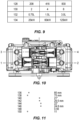
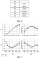
- the table in Figure 15 shows a summary of the resulting technologies that were necessary to achieve the engine parameters that have been set for the engine performance. It can be seen that the core of the proposed SYTECH engine family includes low cost, readily available technology features of common engines, such as fixed intake and exhaust camshaft timing (which is well suited for non-transient REX applications), Port fuel injection and combined Catalytic converter with GPF. As a result, this engine should be a low cost engine with maximum reliability.
- Figure 16 shows performance vales of the 1.5 litre SYTECH engine and Figure 17 shows engine performance.
- Figures 16 and 17 show the modelled performance results of ASFT's new 1.5 engine with 62 kW peak power at 4500 RPM.
- the engine is designed to provide a high power output, Normally Aspirated even with RON 92 fuel. This target is represented by the peak torque of 140 Nm at 3000 rpm engine speed.
- FEV and ASFT applied advanced engineering methods to ensure a fast, stable and efficient combustion, while maintaining low friction, good NVH and a lightweight design.
- the base design of ASFT's new 1.5 l engine needs to be capable of withstanding the forces and loads generated by combustion whilst being reliable, light- weight, low cost and low friction. Friction is a major consideration when designing an efficient engine.
- the SYTECH piston-to-crank connection is unique, during the FEV analysis and modelling we had to assume a friction level that was based on previous SYTECH engines.
- the SYTECH engine should have a lower friction level overall as it has only 3 main bearings and two connecting Rod bearings for a 4 cylinder engine, as opposed to 5 main bearings and 4 connecting rod bearings as is the case for most conventional inline 4 cylinder engines.
- the SYTECH engine does have an additional slider bearing but the slider bearing causes the piston to have almost no side forces so the overall piston friction is lower.
- timing drive For the timing drive, a belt has been chosen to combine the benefits of excellent robustness and a state-of-the-art NVH behavior and good serviceability. At the same time, the layout of the complete timing drive has been optimized in close cooperation with the belt drive system supplier to achieve a very low friction level and minimize belt harmonics and whipping.
- the valve train uses roller finger followers (RFF) and hydraulic lash adjusters (HLA) for low friction and maintenance free operation.
- the valve spring design was analyzed and optimized in detail with kinematic and dynamic valve train simulations to ensure safe operation in the complete speed range.
- the balance shaft on the SYTECH engine runs at engine speed and this is directly chain driven off the crankshaft.
- the oil pump is located around the crankshaft so that no drive related friction losses need be considered.
- combustion models used in the concept design study will be used for validation purposes and help further identify any areas for combustion system optimization following the first round of Thermodynamic testing.
- the lead engine of this cooperative development is ASFT's new 1.5 litre opposed piston engine, which is designed for outstanding performance and good fuel efficiency at a low cost using RON 92 fuel.
- ASFT's new engine family does not only provide outstanding performance with minimal technology, but it has also been protected for the application of more sophisticated future technologies such as cooled EGR, Direct Injection and Turbocharging.
- the new 1.5 l SYTECH engine according to an example of the invention is a Low Cost Unique solution for Modern Range Extenders.
Landscapes
- Engineering & Computer Science (AREA)
- General Engineering & Computer Science (AREA)
- Mechanical Engineering (AREA)
- Chemical & Material Sciences (AREA)
- Combustion & Propulsion (AREA)
- Shafts, Cranks, Connecting Bars, And Related Bearings (AREA)
- Transmission Devices (AREA)
Claims (14)
- Interner Verbrennungsmotor (10), der eine horizontal gegenüberliegende Zylinderanordnung aufweist, die mindestens ein Paar von Kolben (14, 92, 336, 344, 348, 356, 358, 366, 372, 380), die jeweils mit einem Paar von gegenüberliegenden Zylindern (12) der Zylinderanordnung assoziiert sind, und eine Abtriebswelle (16) beinhaltet, wobei jeder der Kolben
für eine hin- und hergehende Bewegung innerhalb eines jeweiligen Zylinders angeordnet ist, die durch Verbrennung angetrieben wird, und wobei die Kolben durch eine Kupplung mit der Ausgangswelle gekoppelt sind, sodass die hin- und hergehende Bewegung der Kolben eine Drehung der Ausgangswelle antreibt, wobei die Kupplung eine Pleuelstange (86, 338, 342, 350, 354, 360, 364, 374, 378), die beweglich mit einem jeweiligen Paar von Kolben verbunden ist, sodass jeder Kolben in seinem assoziierten Zylinder zentriert werden kann, ein Gleitlager (90, 288, 300, 340, 352, 362, 376, 394), das sich für eine hin- und hergehende Bewegung in Bezug auf die Pleuelstange befindet, und eine Kurbelwelle (88, 198, 512), die drehbar innerhalb des Gleitlagers montiert ist, wobei die Kurbelwelle mindestens eine Führungsschulter (504) zum Unterstützen einer axialen Positionierung in Bezug auf das Gleitlager aufweist, beinhaltet. - Interner Verbrennungsmotor nach Anspruch 1, wobei die Kurbelwelle ein Paar gegenüberliegende Führungsschultern aufweist, um sich an oder in der Nähe von gegenüberliegenden Seiten des Gleitlagers zu befinden.
- Interner Verbrennungsmotor nach Anspruch 2, wobei die Schultern beabstandet sind, um einen Spalt zwischen dem Gleitlager und den Schultern zu bilden, wobei der Spalt eine relative Bewegung des Gleitlagers in axialer Richtung zwischen den Schultern ermöglicht, damit sich die Pleuelstange in Bezug auf die Kurbelwelle selbst zentrieren kann.
- Interner Verbrennungsmotor nach einem der vorherigen Ansprüche, wobei die Pleuelstange durch eine schwimmende Verbindung mit dem jeweiligen Paar von gegenüberliegenden Zylindern gekoppelt ist, um einen Versatz zwischen Zylinder und Bohrung auszugleichen.
- Interner Verbrennungsmotor nach Anspruch 4, wobei die schwimmende Verbindung eine Verdrehung in einer oder mehreren Richtungen und/oder einen Versatz zwischen Kurbelwelle und Bohrung ausgleicht.
- Interner Verbrennungsmotor nach einem der Ansprüche 1 bis 5, wobei die Schultern wie folgt sind:sich radial nach außen verjüngend, um jeweils einen größeren Innenradius gegenüber dem Gleitlager aufzuweisen; und/odersich nach außen zu dem Gleitlager hin verjüngend, um eine größere Führungsschulterfläche für den Anschlag zu schaffen, um eine Bewegung in Bezug auf das Gleitlager zu begrenzen.
- Interner Verbrennungsmotor nach einem der Ansprüche 1 bis 6, wobei die Führungsschulter eine Selbstausrichtung der Pleuelstange ermöglicht.
- Interner Verbrennungsmotor nach einem der Ansprüche 1 bis 7, wobei die Kurbelwelle mit einem radial nach außen zu einer Innenfläche des Gleitlagers gerichteten Schmierkanal versehen ist.
- Interner Verbrennungsmotor nach einem der Ansprüche 1 bis 8, wobei die Kupplung angeordnet ist, sodass der Kolben bei konstanter Drehgeschwindigkeit der Abtriebswelle eine sinusförmige Bewegung aufweist, wenn er gegen einen Drehwinkel der Abtriebswelle aufgetragen wird.
- Interner Verbrennungsmotor nach einem der Ansprüche 1 bis 9, wobei der Motor in Form eines Scotch-Yoke-Motors ist.
- Motor nach einem der Ansprüche 1 bis 10, wobei die Pleuelstange Seitenführungen zum Führen des Gleitlagers aufweist.
- Interner Verbrennungsmotor nach einem der Ansprüche 1 bis 11, wobei die Pleuelstange aus einem Paar gleichartiger Teile gebildet ist, die aneinander befestigt sind, wobei eines der gleichartigen Teile vor einem Befestigen gegenüber dem anderen der gleichartigen Teile umgedreht ist.
- Interner Verbrennungsmotor nach einem der Ansprüche 1 bis 12,
wobei
der interne Verbrennungsmotor ein Ansaugsystem beinhaltet, das angeordnet ist, um eine zyklonale Luftströmung in einer Luftkammer des Ansaugsystems zu erzeugen. - Verfahren zum Herstellen eines internen Verbrennungsmotors nach einem der Ansprüche 1 bis 13, das Folgendes beinhaltet:Messen und/oder Modellieren einer Ladungsdichte in dem Zylinder, um Daten zu erlangen; undVerwenden der Daten zur Optimierung eines oder mehrerer Parameter des Motors, um eine Aufrechterhaltung eines Gaszustands mit einer höheren Ladungsdichte um den oberen Totpunkt herum zu erhöhen, um ein verbessertes Kraftstoffgemisch zu erreichen.
Applications Claiming Priority (2)
| Application Number | Priority Date | Filing Date | Title |
|---|---|---|---|
| AU2019904074A AU2019904074A0 (en) | 2019-10-29 | Internal combustion engine - Scotch yoke piston connecting rod and crankshaft guide | |
| PCT/AU2020/051170 WO2021081586A1 (en) | 2019-10-29 | 2020-10-29 | Internal combustion engine having crankshaft guide |
Publications (3)
| Publication Number | Publication Date |
|---|---|
| EP4051876A1 EP4051876A1 (de) | 2022-09-07 |
| EP4051876A4 EP4051876A4 (de) | 2023-11-08 |
| EP4051876B1 true EP4051876B1 (de) | 2025-02-12 |
Family
ID=75714427
Family Applications (1)
| Application Number | Title | Priority Date | Filing Date |
|---|---|---|---|
| EP20881761.9A Active EP4051876B1 (de) | 2019-10-29 | 2020-10-29 | Brennkraftmaschine mit einer kurbelwellenführung |
Country Status (5)
| Country | Link |
|---|---|
| US (1) | US12140074B2 (de) |
| EP (1) | EP4051876B1 (de) |
| AU (1) | AU2020373162B2 (de) |
| ES (1) | ES3024619T3 (de) |
| WO (1) | WO2021081586A1 (de) |
Family Cites Families (10)
| Publication number | Priority date | Publication date | Assignee | Title |
|---|---|---|---|---|
| US2513514A (en) | 1945-10-08 | 1950-07-04 | Robert A Poage | Piston and crankshaft connecting means for internal-combustion engines |
| GB8608237D0 (en) | 1986-04-04 | 1986-05-08 | Collins Motor Corp Ltd | Reciprocatory positive displacement machines |
| US4825820A (en) * | 1987-11-09 | 1989-05-02 | Morgan George R | Power system for piston engines & compression devices |
| US5331926A (en) * | 1993-07-23 | 1994-07-26 | Denner, Inc. | Dwelling scotch yoke engine |
| AUPR045600A0 (en) * | 2000-09-29 | 2000-10-26 | Raffaele, Peter Robert | Fluid devices |
| DE102007056203A1 (de) | 2007-11-22 | 2008-11-20 | Audi Ag | Vorrichtung zur Schmierung von Kurbelwellen- und Pleuellagern einer Kurbelwelle einer Brennkraftmaschine |
| US8215268B2 (en) * | 2008-12-19 | 2012-07-10 | Claudio Barberato | Three-stroke internal combustion engine, cycle and components |
| US8550041B2 (en) * | 2009-02-20 | 2013-10-08 | Achates Power, Inc. | Cylinder and piston assemblies for opposed piston engines |
| CN102985638B (zh) | 2010-04-07 | 2016-05-18 | 依达克斯研发国际私人有限公司 | 改进的燃烧发动机 |
| GB201413345D0 (en) | 2014-07-28 | 2014-09-10 | Oxford Two Stroke Ltd | Internal combustion engine |
-
2020
- 2020-10-29 US US17/772,356 patent/US12140074B2/en active Active
- 2020-10-29 EP EP20881761.9A patent/EP4051876B1/de active Active
- 2020-10-29 AU AU2020373162A patent/AU2020373162B2/en active Active
- 2020-10-29 ES ES20881761T patent/ES3024619T3/es active Active
- 2020-10-29 WO PCT/AU2020/051170 patent/WO2021081586A1/en not_active Ceased
Also Published As
| Publication number | Publication date |
|---|---|
| EP4051876A4 (de) | 2023-11-08 |
| AU2020373162B2 (en) | 2025-09-18 |
| AU2020373162A1 (en) | 2022-05-26 |
| WO2021081586A1 (en) | 2021-05-06 |
| EP4051876A1 (de) | 2022-09-07 |
| US12140074B2 (en) | 2024-11-12 |
| ES3024619T3 (en) | 2025-06-04 |
| US20220381180A1 (en) | 2022-12-01 |
Similar Documents
| Publication | Publication Date | Title |
|---|---|---|
| Toda et al. | The new Toyota inline 4-cylinder 2.5 L gasoline engine | |
| EP4051873B1 (de) | Verbrennungsmotor mit verbesserter ölpumpenanordnung | |
| CN112746899B (zh) | 内燃发动机 | |
| CN112746898B (zh) | 具有苏格兰轭式活塞连杆和曲轴引导件的内燃发动机 | |
| Coltman et al. | Project Sabre: A Close-Spaced Direct Injection 3-Cylinder Engine with Synergistic Technologies to Achieve Low CO₂ Output | |
| EP4051877B1 (de) | Brennkraftmaschine mit gezielter motorschmierung | |
| EP4051875B1 (de) | Verbrennungsmotor mit konzentrischer nockenwelle und ausgleichswelle | |
| EP4051876B1 (de) | Brennkraftmaschine mit einer kurbelwellenführung | |
| US12366200B2 (en) | Internal combustion engine | |
| CN112746900B (zh) | 具有同轴凸轮轴和平衡轴的内燃发动机 | |
| CN112746896B (zh) | 具有改进型机油泵装置的内燃发动机 | |
| CN112746897B (zh) | 具有有针对性的发动机润滑的内燃发动机 | |
| Mattarelli et al. | Commercial Vehicles: New Diesel Engine Concepts for Euro VI and Beyond | |
| Anning et al. | Opposed stepped piston engines: Affordable power for sustainability and low emissions | |
| Sykes et al. | 1.25 L Turbocharged Diesel for Demanding Non-Road Applications | |
| dos Santos et al. | Single Cylinder Research Engine Development for Ultra-High Pressure Direct Injection of Ethanol and Gasoline Investigations |
Legal Events
| Date | Code | Title | Description |
|---|---|---|---|
| STAA | Information on the status of an ep patent application or granted ep patent |
Free format text: STATUS: THE INTERNATIONAL PUBLICATION HAS BEEN MADE |
|
| PUAI | Public reference made under article 153(3) epc to a published international application that has entered the european phase |
Free format text: ORIGINAL CODE: 0009012 |
|
| STAA | Information on the status of an ep patent application or granted ep patent |
Free format text: STATUS: REQUEST FOR EXAMINATION WAS MADE |
|
| 17P | Request for examination filed |
Effective date: 20220527 |
|
| AK | Designated contracting states |
Kind code of ref document: A1 Designated state(s): AL AT BE BG CH CY CZ DE DK EE ES FI FR GB GR HR HU IE IS IT LI LT LU LV MC MK MT NL NO PL PT RO RS SE SI SK SM TR |
|
| DAV | Request for validation of the european patent (deleted) | ||
| DAX | Request for extension of the european patent (deleted) | ||
| P01 | Opt-out of the competence of the unified patent court (upc) registered |
Effective date: 20230510 |
|
| RIC1 | Information provided on ipc code assigned before grant |
Ipc: F16C 3/04 20060101ALI20230523BHEP Ipc: F16H 21/36 20060101ALI20230523BHEP Ipc: F02B 75/32 20060101ALI20230523BHEP Ipc: F02B 75/24 20060101ALI20230523BHEP Ipc: F01B 9/02 20060101AFI20230523BHEP |
|
| RIC1 | Information provided on ipc code assigned before grant |
Ipc: F16C 3/04 20060101ALI20230606BHEP Ipc: F16H 21/36 20060101ALI20230606BHEP Ipc: F02B 75/32 20060101ALI20230606BHEP Ipc: F02B 75/24 20060101ALI20230606BHEP Ipc: F01B 9/02 20060101AFI20230606BHEP |
|
| RIC1 | Information provided on ipc code assigned before grant |
Ipc: F16C 3/04 20060101ALI20230616BHEP Ipc: F16H 21/36 20060101ALI20230616BHEP Ipc: F02B 75/32 20060101ALI20230616BHEP Ipc: F02B 75/24 20060101ALI20230616BHEP Ipc: F01B 9/02 20060101AFI20230616BHEP |
|
| A4 | Supplementary search report drawn up and despatched |
Effective date: 20231010 |
|
| RIC1 | Information provided on ipc code assigned before grant |
Ipc: F16C 3/04 20060101ALI20231004BHEP Ipc: F16H 21/36 20060101ALI20231004BHEP Ipc: F02B 75/32 20060101ALI20231004BHEP Ipc: F02B 75/24 20060101ALI20231004BHEP Ipc: F01B 9/02 20060101AFI20231004BHEP |
|
| GRAP | Despatch of communication of intention to grant a patent |
Free format text: ORIGINAL CODE: EPIDOSNIGR1 |
|
| STAA | Information on the status of an ep patent application or granted ep patent |
Free format text: STATUS: GRANT OF PATENT IS INTENDED |
|
| INTG | Intention to grant announced |
Effective date: 20240830 |
|
| GRAS | Grant fee paid |
Free format text: ORIGINAL CODE: EPIDOSNIGR3 |
|
| GRAA | (expected) grant |
Free format text: ORIGINAL CODE: 0009210 |
|
| STAA | Information on the status of an ep patent application or granted ep patent |
Free format text: STATUS: THE PATENT HAS BEEN GRANTED |
|
| AK | Designated contracting states |
Kind code of ref document: B1 Designated state(s): AL AT BE BG CH CY CZ DE DK EE ES FI FR GB GR HR HU IE IS IT LI LT LU LV MC MK MT NL NO PL PT RO RS SE SI SK SM TR |
|
| REG | Reference to a national code |
Ref country code: GB Ref legal event code: FG4D |
|
| REG | Reference to a national code |
Ref country code: CH Ref legal event code: EP |
|
| REG | Reference to a national code |
Ref country code: DE Ref legal event code: R096 Ref document number: 602020046104 Country of ref document: DE |
|
| REG | Reference to a national code |
Ref country code: IE Ref legal event code: FG4D |
|
| REG | Reference to a national code |
Ref country code: ES Ref legal event code: FG2A Ref document number: 3024619 Country of ref document: ES Kind code of ref document: T3 Effective date: 20250604 |
|
| REG | Reference to a national code |
Ref country code: NL Ref legal event code: MP Effective date: 20250212 |
|
| PG25 | Lapsed in a contracting state [announced via postgrant information from national office to epo] |
Ref country code: RS Free format text: LAPSE BECAUSE OF FAILURE TO SUBMIT A TRANSLATION OF THE DESCRIPTION OR TO PAY THE FEE WITHIN THE PRESCRIBED TIME-LIMIT Effective date: 20250512 |
|
| PG25 | Lapsed in a contracting state [announced via postgrant information from national office to epo] |
Ref country code: FI Free format text: LAPSE BECAUSE OF FAILURE TO SUBMIT A TRANSLATION OF THE DESCRIPTION OR TO PAY THE FEE WITHIN THE PRESCRIBED TIME-LIMIT Effective date: 20250212 |
|
| PG25 | Lapsed in a contracting state [announced via postgrant information from national office to epo] |
Ref country code: PL Free format text: LAPSE BECAUSE OF FAILURE TO SUBMIT A TRANSLATION OF THE DESCRIPTION OR TO PAY THE FEE WITHIN THE PRESCRIBED TIME-LIMIT Effective date: 20250212 |
|
| REG | Reference to a national code |
Ref country code: LT Ref legal event code: MG9D |
|
| PG25 | Lapsed in a contracting state [announced via postgrant information from national office to epo] |
Ref country code: IS Free format text: LAPSE BECAUSE OF FAILURE TO SUBMIT A TRANSLATION OF THE DESCRIPTION OR TO PAY THE FEE WITHIN THE PRESCRIBED TIME-LIMIT Effective date: 20250612 Ref country code: NO Free format text: LAPSE BECAUSE OF FAILURE TO SUBMIT A TRANSLATION OF THE DESCRIPTION OR TO PAY THE FEE WITHIN THE PRESCRIBED TIME-LIMIT Effective date: 20250512 |
|
| PG25 | Lapsed in a contracting state [announced via postgrant information from national office to epo] |
Ref country code: NL Free format text: LAPSE BECAUSE OF FAILURE TO SUBMIT A TRANSLATION OF THE DESCRIPTION OR TO PAY THE FEE WITHIN THE PRESCRIBED TIME-LIMIT Effective date: 20250212 |
|
| PG25 | Lapsed in a contracting state [announced via postgrant information from national office to epo] |
Ref country code: HR Free format text: LAPSE BECAUSE OF FAILURE TO SUBMIT A TRANSLATION OF THE DESCRIPTION OR TO PAY THE FEE WITHIN THE PRESCRIBED TIME-LIMIT Effective date: 20250212 |
|
| PG25 | Lapsed in a contracting state [announced via postgrant information from national office to epo] |
Ref country code: LV Free format text: LAPSE BECAUSE OF FAILURE TO SUBMIT A TRANSLATION OF THE DESCRIPTION OR TO PAY THE FEE WITHIN THE PRESCRIBED TIME-LIMIT Effective date: 20250212 Ref country code: PT Free format text: LAPSE BECAUSE OF FAILURE TO SUBMIT A TRANSLATION OF THE DESCRIPTION OR TO PAY THE FEE WITHIN THE PRESCRIBED TIME-LIMIT Effective date: 20250612 |
|
| PGFP | Annual fee paid to national office [announced via postgrant information from national office to epo] |
Ref country code: FR Payment date: 20250611 Year of fee payment: 6 |
|
| PG25 | Lapsed in a contracting state [announced via postgrant information from national office to epo] |
Ref country code: GR Free format text: LAPSE BECAUSE OF FAILURE TO SUBMIT A TRANSLATION OF THE DESCRIPTION OR TO PAY THE FEE WITHIN THE PRESCRIBED TIME-LIMIT Effective date: 20250513 Ref country code: BG Free format text: LAPSE BECAUSE OF FAILURE TO SUBMIT A TRANSLATION OF THE DESCRIPTION OR TO PAY THE FEE WITHIN THE PRESCRIBED TIME-LIMIT Effective date: 20250212 |
|
| REG | Reference to a national code |
Ref country code: AT Ref legal event code: MK05 Ref document number: 1766203 Country of ref document: AT Kind code of ref document: T Effective date: 20250212 |
|
| PG25 | Lapsed in a contracting state [announced via postgrant information from national office to epo] |
Ref country code: SE Free format text: LAPSE BECAUSE OF FAILURE TO SUBMIT A TRANSLATION OF THE DESCRIPTION OR TO PAY THE FEE WITHIN THE PRESCRIBED TIME-LIMIT Effective date: 20250212 |
|
| PG25 | Lapsed in a contracting state [announced via postgrant information from national office to epo] |
Ref country code: SM Free format text: LAPSE BECAUSE OF FAILURE TO SUBMIT A TRANSLATION OF THE DESCRIPTION OR TO PAY THE FEE WITHIN THE PRESCRIBED TIME-LIMIT Effective date: 20250212 |
|
| PG25 | Lapsed in a contracting state [announced via postgrant information from national office to epo] |
Ref country code: DK Free format text: LAPSE BECAUSE OF FAILURE TO SUBMIT A TRANSLATION OF THE DESCRIPTION OR TO PAY THE FEE WITHIN THE PRESCRIBED TIME-LIMIT Effective date: 20250212 |
|
| PG25 | Lapsed in a contracting state [announced via postgrant information from national office to epo] |
Ref country code: IT Free format text: LAPSE BECAUSE OF FAILURE TO SUBMIT A TRANSLATION OF THE DESCRIPTION OR TO PAY THE FEE WITHIN THE PRESCRIBED TIME-LIMIT Effective date: 20250212 |
|
| PGFP | Annual fee paid to national office [announced via postgrant information from national office to epo] |
Ref country code: GB Payment date: 20250801 Year of fee payment: 6 |
|
| PG25 | Lapsed in a contracting state [announced via postgrant information from national office to epo] |
Ref country code: AT Free format text: LAPSE BECAUSE OF FAILURE TO SUBMIT A TRANSLATION OF THE DESCRIPTION OR TO PAY THE FEE WITHIN THE PRESCRIBED TIME-LIMIT Effective date: 20250212 |
|
| PG25 | Lapsed in a contracting state [announced via postgrant information from national office to epo] |
Ref country code: CZ Free format text: LAPSE BECAUSE OF FAILURE TO SUBMIT A TRANSLATION OF THE DESCRIPTION OR TO PAY THE FEE WITHIN THE PRESCRIBED TIME-LIMIT Effective date: 20250212 Ref country code: EE Free format text: LAPSE BECAUSE OF FAILURE TO SUBMIT A TRANSLATION OF THE DESCRIPTION OR TO PAY THE FEE WITHIN THE PRESCRIBED TIME-LIMIT Effective date: 20250212 |
|
| PG25 | Lapsed in a contracting state [announced via postgrant information from national office to epo] |
Ref country code: RO Free format text: LAPSE BECAUSE OF FAILURE TO SUBMIT A TRANSLATION OF THE DESCRIPTION OR TO PAY THE FEE WITHIN THE PRESCRIBED TIME-LIMIT Effective date: 20250212 |
|
| PG25 | Lapsed in a contracting state [announced via postgrant information from national office to epo] |
Ref country code: SK Free format text: LAPSE BECAUSE OF FAILURE TO SUBMIT A TRANSLATION OF THE DESCRIPTION OR TO PAY THE FEE WITHIN THE PRESCRIBED TIME-LIMIT Effective date: 20250212 |
|
| REG | Reference to a national code |
Ref country code: DE Ref legal event code: R097 Ref document number: 602020046104 Country of ref document: DE |
|
| PLBE | No opposition filed within time limit |
Free format text: ORIGINAL CODE: 0009261 |
|
| STAA | Information on the status of an ep patent application or granted ep patent |
Free format text: STATUS: NO OPPOSITION FILED WITHIN TIME LIMIT |
|
| PGFP | Annual fee paid to national office [announced via postgrant information from national office to epo] |
Ref country code: DE Payment date: 20250610 Year of fee payment: 6 |
|
| 26N | No opposition filed |
Effective date: 20251113 |
|
| PGFP | Annual fee paid to national office [announced via postgrant information from national office to epo] |
Ref country code: ES Payment date: 20251118 Year of fee payment: 6 |