EP4051071B1 - Separator configuration for a floor cleaner - Google Patents
Separator configuration for a floor cleaner Download PDFInfo
- Publication number
- EP4051071B1 EP4051071B1 EP20811852.1A EP20811852A EP4051071B1 EP 4051071 B1 EP4051071 B1 EP 4051071B1 EP 20811852 A EP20811852 A EP 20811852A EP 4051071 B1 EP4051071 B1 EP 4051071B1
- Authority
- EP
- European Patent Office
- Prior art keywords
- fluid
- container
- rib
- vertical
- sidewall
- Prior art date
- Legal status (The legal status is an assumption and is not a legal conclusion. Google has not performed a legal analysis and makes no representation as to the accuracy of the status listed.)
- Active
Links
- 239000012530 fluid Substances 0.000 claims description 91
- 238000011084 recovery Methods 0.000 claims description 28
- 238000004140 cleaning Methods 0.000 claims description 26
- 238000000926 separation method Methods 0.000 claims description 15
- 239000007788 liquid Substances 0.000 claims description 10
- 239000003599 detergent Substances 0.000 description 2
- XLYOFNOQVPJJNP-UHFFFAOYSA-N water Substances O XLYOFNOQVPJJNP-UHFFFAOYSA-N 0.000 description 2
- 238000010276 construction Methods 0.000 description 1
- 238000007599 discharging Methods 0.000 description 1
- 230000005484 gravity Effects 0.000 description 1
- 239000011121 hardwood Substances 0.000 description 1
- 239000000203 mixture Substances 0.000 description 1
Images


Classifications
-
- A—HUMAN NECESSITIES
- A47—FURNITURE; DOMESTIC ARTICLES OR APPLIANCES; COFFEE MILLS; SPICE MILLS; SUCTION CLEANERS IN GENERAL
- A47L—DOMESTIC WASHING OR CLEANING; SUCTION CLEANERS IN GENERAL
- A47L11/00—Machines for cleaning floors, carpets, furniture, walls, or wall coverings
- A47L11/40—Parts or details of machines not provided for in groups A47L11/02 - A47L11/38, or not restricted to one of these groups, e.g. handles, arrangements of switches, skirts, buffers, levers
- A47L11/4013—Contaminants collecting devices, i.e. hoppers, tanks or the like
- A47L11/4016—Contaminants collecting devices, i.e. hoppers, tanks or the like specially adapted for collecting fluids
-
- A—HUMAN NECESSITIES
- A47—FURNITURE; DOMESTIC ARTICLES OR APPLIANCES; COFFEE MILLS; SPICE MILLS; SUCTION CLEANERS IN GENERAL
- A47L—DOMESTIC WASHING OR CLEANING; SUCTION CLEANERS IN GENERAL
- A47L11/00—Machines for cleaning floors, carpets, furniture, walls, or wall coverings
- A47L11/02—Floor surfacing or polishing machines
- A47L11/20—Floor surfacing or polishing machines combined with vacuum cleaning devices
- A47L11/201—Floor surfacing or polishing machines combined with vacuum cleaning devices with supply of cleaning agents
-
- A—HUMAN NECESSITIES
- A47—FURNITURE; DOMESTIC ARTICLES OR APPLIANCES; COFFEE MILLS; SPICE MILLS; SUCTION CLEANERS IN GENERAL
- A47L—DOMESTIC WASHING OR CLEANING; SUCTION CLEANERS IN GENERAL
- A47L9/00—Details or accessories of suction cleaners, e.g. mechanical means for controlling the suction or for effecting pulsating action; Storing devices specially adapted to suction cleaners or parts thereof; Carrying-vehicles specially adapted for suction cleaners
- A47L9/10—Filters; Dust separators; Dust removal; Automatic exchange of filters
- A47L9/102—Dust separators
-
- A—HUMAN NECESSITIES
- A47—FURNITURE; DOMESTIC ARTICLES OR APPLIANCES; COFFEE MILLS; SPICE MILLS; SUCTION CLEANERS IN GENERAL
- A47L—DOMESTIC WASHING OR CLEANING; SUCTION CLEANERS IN GENERAL
- A47L11/00—Machines for cleaning floors, carpets, furniture, walls, or wall coverings
- A47L11/29—Floor-scrubbing machines characterised by means for taking-up dirty liquid
- A47L11/30—Floor-scrubbing machines characterised by means for taking-up dirty liquid by suction
-
- A—HUMAN NECESSITIES
- A47—FURNITURE; DOMESTIC ARTICLES OR APPLIANCES; COFFEE MILLS; SPICE MILLS; SUCTION CLEANERS IN GENERAL
- A47L—DOMESTIC WASHING OR CLEANING; SUCTION CLEANERS IN GENERAL
- A47L11/00—Machines for cleaning floors, carpets, furniture, walls, or wall coverings
- A47L11/40—Parts or details of machines not provided for in groups A47L11/02 - A47L11/38, or not restricted to one of these groups, e.g. handles, arrangements of switches, skirts, buffers, levers
- A47L11/408—Means for supplying cleaning or surface treating agents
- A47L11/4083—Liquid supply reservoirs; Preparation of the agents, e.g. mixing devices
-
- A—HUMAN NECESSITIES
- A47—FURNITURE; DOMESTIC ARTICLES OR APPLIANCES; COFFEE MILLS; SPICE MILLS; SUCTION CLEANERS IN GENERAL
- A47L—DOMESTIC WASHING OR CLEANING; SUCTION CLEANERS IN GENERAL
- A47L7/00—Suction cleaners adapted for additional purposes; Tables with suction openings for cleaning purposes; Containers for cleaning articles by suction; Suction cleaners adapted to cleaning of brushes; Suction cleaners adapted to taking-up liquids
- A47L7/0004—Suction cleaners adapted to take up liquids, e.g. wet or dry vacuum cleaners
-
- A—HUMAN NECESSITIES
- A47—FURNITURE; DOMESTIC ARTICLES OR APPLIANCES; COFFEE MILLS; SPICE MILLS; SUCTION CLEANERS IN GENERAL
- A47L—DOMESTIC WASHING OR CLEANING; SUCTION CLEANERS IN GENERAL
- A47L9/00—Details or accessories of suction cleaners, e.g. mechanical means for controlling the suction or for effecting pulsating action; Storing devices specially adapted to suction cleaners or parts thereof; Carrying-vehicles specially adapted for suction cleaners
Definitions
- the present disclosure relates to extractor cleaning machines, and more particularly, to separator configurations for extractor cleaning machines.
- An extractor cleaning machine typically includes a separator for separating air from cleaning liquid prior to discharging the air.
- DE202016104991 discloses a surface cleaning device comprising a housing containing an upright assembly and a base attached to the upright assembly, a fluid tank provided on the housing, a fluid manifold provided in the base in fluid communication with the fluid container, a working air path through the housing, and a recovery tank provided on the housing and defining a portion of the working air path.
- the invention provides a cleaning machine having a housing, a fluid distributor that dispenses fluid, a supply tank connected to the housing to supply fluid to the fluid distributor, and a suction nozzle that engages a surface to be cleaned.
- a suction source is positioned within the housing and is in fluid communication with the suction nozzle to draw fluid into the suction nozzle from the surface to be cleaned.
- a recovery tank is selectively mounted on the housing and in fluid communication with the suction nozzle and the suction source to store fluid drawn through the suction nozzle.
- the recovery tank includes a container having a bottom wall and sidewalls projecting upwardly from the bottom wall thereby defining an open top, a cover coupled to the open top of the container, and an air-liquid separator extending into the recovery tank from the open top.
- the air-liquid separator has a vertical sidewall, a lower wall extending laterally from the lower end of the vertical sidewall toward an adjacent sidewall of the sidewalls of the container.
- the vertical sidewall, the lower wall, and the adjacent sidewall define a separation chamber.
- the vertical sidewall includes a rib extending outwardly from the vertical sidewall and into the separation chamber.
- the separation chamber includes a dirty fluid inlet receiving fluid from the suction nozzle through the cover, a first dirty fluid outlet directing fluid from the separation chamber into the container, and a second dirty fluid outlet directing fluid from the separation chamber into the container.
- the rib is positioned between the first dirty fluid outlet and the second dirty fluid outlet.
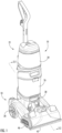
- FIGS. 1 and 2 illustrate an extractor cleaning machine 10 (hereinafter referred "extractor").
- the extractor 10 is an upright extractor operable to clean a surface 14, such as, for example, a floor ( FIG. 2 ).
- the extractor 10 may be adapted to clean a variety of surfaces, such as carpets, hardwood floors, tiles, or the like.
- a cleaning fluid e.g., water, detergent, or a mixture of water and detergent
- the extractor 10 then draws the cleaning fluid and dirt from the surface, leaving the surface relatively clean.
- the illustrated extractor 10 includes a base 18, a body 22 coupled to the base 18, a recovery tank 26 coupled to the body 22, a suction source 30, a fluid distribution system (not shown), a supply tank assembly 34 coupled to the body 22, two wheels 38, a suction nozzle 42 and a brush assembly 46.
- the recovery tank 26 includes an air-liquid separator 26 configured to separate air from the cleaning fluid drawn from the surface.
- the air-liquid separator 62 includes a rib 90 downstream from the inlet to the recovery tank 26 to direct a first flow path on a first side of the rib 90 and direct a second flow path on a second side of the rib 90 as described below.
- extractors within the scope of the disclosure may include a different type of base, such as including the recovery tank and or supply tank coupled to the base.
- other extractors may be different than the illustrated upright configuration.
- other embodiments of the extractor may include hand held or portable extractors also known as spot cleaners.
- the base 18 is movable along the surface 14 to be cleaned.
- two wheels 38 are coupled to the base 18 to facilitate movement of the base 18 along the surface 14. In other embodiments more than two wheels can be utilized. In the illustrated embodiment, the wheels 38 are idle wheels. In other embodiments, one or both of the wheels 38 may be driven wheels.
- the illustrated body 22 includes a housing and is pivotally coupled to and extends from the base 18.
- the body 22 is pivotable or tiltable relative to the base 18 from a generally vertical, or upright, storage position to one or more non-vertical, or inclined, operating positions. Pivoting the body 22 to an operating position facilitates moving the base 18 along the surface 14.
- the recovery tank 26 is in fluid communication with the suction nozzle 42 and the suction source 30.
- the recovery tank 26 is configured to store cleaning fluid and any dirt extracted from the surface 14 through the suction nozzle 42.
- the suction source 30 is connected to the body 22 and is in fluid communication with the suction nozzle 42. The suction source 30 draws fluid into the suction nozzle 42 from the surface 14 to be cleaned.
- the supply tank assembly 34 is configured to store cleaning fluid to be distributed by the extractor 10 onto the surface 14.
- the fluid distribution system is in fluid communication with the supply tank assembly 34 to draw cleaning fluid from the supply tank assembly 34 and distribute the fluid to the surface 14 through a distribution nozzle 42.
- the fluid distribution system may include a pump that propels the cleaning fluid to the surface 14.
- gravity moves the cleaning fluid through the distribution nozzle 42 to the surface 14.
- the body 22 supports one or more actuators that control cleaning fluid delivery from the supply tank assembly 34 through a distributor and a distribution nozzle and onto the surface 14.
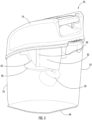
- FIG. 3 illustrates the recovery tank 26 in greater detail.
- the recovery tank 26 is selectively mounted to the body 22 and includes a container 50, a cover 54, a float valve 58, and the air-liquid separator 62 (hereinafter "separator").
- the container 50 has a bottom wall 66 and sidewalls 70 projecting upward from the bottom wall 66 toward an open top.
- the illustrated bottom wall 66 is substantially rectangular and the sidewalls 70 extend around an entire perimeter of the bottom wall 66 and extend upward therefrom.
- the sidewalls 70 are substantially planar, whereas in other embodiments, the sidewalls 70 are curved or slightly curved.
- the cover 54 is removably connected to the open top of the container 50 to close the open top of the container 50 while the cover 54 is installed.
- the cover 54 forms a dirty fluid inlet 74, and a clean air outlet 78.
- the dirty fluid inlet 74 is positioned near the separator 62.
- the dirty fluid inlet 74 permits dirty fluid extracted from the floor 14 to be cleaned by the suction nozzle 42 to flow into the container 50.
- the container 50 retains the dirty fluid until a user detaches the recovery tank 26 from the body 22 and empties the container 50.
- the clean air outlet 78 permits clean air to flow out of the container 50.
- the clean air outlet 78 is spaced from the separator 62.
- the float valve 58 selectively covers the clean air outlet 78 to selectively permit clean air to flow through the clean air outlet 78.
- the float valve 58 permits air flow through the clean air outlet 78.
- the float valve 58 closes the clean air outlet 78 to inhibit air flow through the clean air outlet 78.
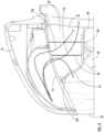
- FIG. 6 illustrates the separator 62 removed from the recovery tank 26.
- the separator 62 has a vertical sidewall 82, a lower wall 86 and a rib 90.
- the vertical sidewall 82 extends downwardly into the recovery tank 26 from the open top of the recovery tank 26.
- the vertical sidewall 82 is substantially parallel to the adjacent sidewall 70 of the container 50.
- the vertical sidewall 82 extends into the recovery tank 26 from the open top of the recovery tank 26 and ends at a location spaced above the bottom wall 66 of the container 50.
- the dirty fluid inlet 74 is positioned on a first side of the vertical sidewall 82 and the clean air outlet 78 is positioned on a second side of the vertical sidewall 82, opposite the first side.
- the float valve 58 is positioned on the second side of the vertical sidewall 82.
- the lower wall 86 extends laterally from a lower end of the vertical sidewall 82 toward an adjacent sidewall 70 of the container 50.
- the lower wall 86 includes a first portion 86A that extends from the dirty fluid inlet 74 to the rib 90, and a second portion 86B that extends from the rib 90 toward a lower wall end 98 proximate the adjacent sidewall of the container 50.
- the first portion includes an aperture 94.
- a first dirty fluid outlet is formed by the aperture 94.
- the aperture 94 is bounded by the adjacent sidewall of the container 50.
- the lower wall end 98 bounded by the vertical sidewall 82 and the adjacent sidewall of the container 50 form a second dirty fluid outlet.
- the vertical sidewall 82, the lower wall 86, and the adjacent sidewall of the container 50 define a separation chamber.
- the separation chamber receives dirty fluid through the dirty fluid inlet 74 from the suction nozzle 42 through the cover 54.
- the separation chamber discharges fluid out of the first dirty fluid outlet (at aperture 94) and the second dirty fluid outlet (at lower wall end 98) into the container 50.
- the rib 90 extends laterally outward from the vertical sidewall 82 toward the adjacent sidewall 70 of the container 50 and into the separation chamber. In some embodiments, the rib 90 extends horizontally outward from the vertical sidewall 82 and vertically upward from the lower wall 86. The rib 90 is positioned between the first dirty fluid outlet and the second dirty fluid outlet. The rib 90 includes a first side facing toward the aperture 94 and a second side facing toward the lower wall end 98.
- the rib 90 is configured to separate dirty fluid into a first flow path 102, a second flow path 106 and a third flow path 110.
- Fluid flowing along the first flow path 102 flows from the dirty fluid inlet 74, contacts the first side of the rib 90 and flows out of the first dirty fluid outlet (at aperture 94).
- Fluid flowing along the second flow path 106 flows from the dirty fluid inlet 74 above the rib 90, contacts the second side of the rib 90 and flows out of the second dirty fluid outlet (at lower wall end 98).
- Fluid flowing along the third flow path 110 flows from the dirty fluid inlet 74 between the rib 90 and the adjacent sidewall 70 of the container 50 and out of the second fluid outlet (at lower wall end 98).
- the rib 90 diverts dirty fluid flow from the dirty fluid inlet 74 into the first flow path 102, the second flow path 106 and the third flow path 110.
- the dirty fluid is slowed down as it enters the container 50 such that fluid settles at a bottom of the container 50 and air is permitted to exit the clean air outlet 78.
Description
- The present disclosure relates to extractor cleaning machines, and more particularly, to separator configurations for extractor cleaning machines.
- An extractor cleaning machine typically includes a separator for separating air from cleaning liquid prior to discharging the air.
-
DE202016104991 discloses a surface cleaning device comprising a housing containing an upright assembly and a base attached to the upright assembly, a fluid tank provided on the housing, a fluid manifold provided in the base in fluid communication with the fluid container, a working air path through the housing, and a recovery tank provided on the housing and defining a portion of the working air path. - The invention provides a cleaning machine having a housing, a fluid distributor that dispenses fluid, a supply tank connected to the housing to supply fluid to the fluid distributor, and a suction nozzle that engages a surface to be cleaned. A suction source is positioned within the housing and is in fluid communication with the suction nozzle to draw fluid into the suction nozzle from the surface to be cleaned. A recovery tank is selectively mounted on the housing and in fluid communication with the suction nozzle and the suction source to store fluid drawn through the suction nozzle. The recovery tank includes a container having a bottom wall and sidewalls projecting upwardly from the bottom wall thereby defining an open top, a cover coupled to the open top of the container, and an air-liquid separator extending into the recovery tank from the open top. The air-liquid separator has a vertical sidewall, a lower wall extending laterally from the lower end of the vertical sidewall toward an adjacent sidewall of the sidewalls of the container. The vertical sidewall, the lower wall, and the adjacent sidewall define a separation chamber. The vertical sidewall includes a rib extending outwardly from the vertical sidewall and into the separation chamber. The separation chamber includes a dirty fluid inlet receiving fluid from the suction nozzle through the cover, a first dirty fluid outlet directing fluid from the separation chamber into the container, and a second dirty fluid outlet directing fluid from the separation chamber into the container. The rib is positioned between the first dirty fluid outlet and the second dirty fluid outlet.
- Other aspects of the disclosure will become apparent by consideration of the detailed description and accompanying drawings.
-
-
FIG. 1 is a perspective view of an extractor cleaning machine according to some embodiments of the invention. -
FIG. 2 is a cross-sectional view taken along line 2-2 ofFIG. 1 . -
FIG. 3 is a perspective view of a recovery tank of the extractor cleaning machine ofFIG. 1 . -
FIG. 4 is a perspective view of the recovery tank with a portion of a cover removed. -
FIG. 5 is a top view of the recovery tank with a portion of the cover removed. -
FIG. 6 is a perspective view of an air-liquid separator of the recovery tank. -
FIG. 7 is a perspective view of a recovery tank of the extractor cleaning machine ofFIG. 1 with a portion of the recovery tank removed. -
FIG. 8 is a close up view of a portion ofFIG. 7 . - Before any embodiments of the disclosure are explained in detail, it is to be understood that the disclosure is not limited in its application to the details of construction and the arrangement of components set forth in the following description or illustrated in the following drawings. The disclosure is capable of other embodiments and of being practiced or of being carried out in various ways.
-
FIGS. 1 and2 illustrate an extractor cleaning machine 10 (hereinafter referred "extractor"). In the illustrated embodiment, theextractor 10 is an upright extractor operable to clean asurface 14, such as, for example, a floor (FIG. 2 ). In some embodiments, theextractor 10 may be adapted to clean a variety of surfaces, such as carpets, hardwood floors, tiles, or the like. A cleaning fluid (e.g., water, detergent, or a mixture of water and detergent) is dispensed onto the surface to clean thesurface 14. Theextractor 10 then draws the cleaning fluid and dirt from the surface, leaving the surface relatively clean. - The illustrated
extractor 10 includes abase 18, abody 22 coupled to thebase 18, arecovery tank 26 coupled to thebody 22, asuction source 30, a fluid distribution system (not shown), asupply tank assembly 34 coupled to thebody 22, twowheels 38, asuction nozzle 42 and abrush assembly 46. Therecovery tank 26 includes an air-liquid separator 26 configured to separate air from the cleaning fluid drawn from the surface. The air-liquid separator 62 includes arib 90 downstream from the inlet to therecovery tank 26 to direct a first flow path on a first side of therib 90 and direct a second flow path on a second side of therib 90 as described below. Other extractors within the scope of the disclosure may include a different type of base, such as including the recovery tank and or supply tank coupled to the base. In addition, other extractors may be different than the illustrated upright configuration. For example, other embodiments of the extractor may include hand held or portable extractors also known as spot cleaners. - The
base 18 is movable along thesurface 14 to be cleaned. In the illustrated embodiment, twowheels 38 are coupled to thebase 18 to facilitate movement of thebase 18 along thesurface 14. In other embodiments more than two wheels can be utilized. In the illustrated embodiment, thewheels 38 are idle wheels. In other embodiments, one or both of thewheels 38 may be driven wheels. - The illustrated
body 22 includes a housing and is pivotally coupled to and extends from thebase 18. Thebody 22 is pivotable or tiltable relative to thebase 18 from a generally vertical, or upright, storage position to one or more non-vertical, or inclined, operating positions. Pivoting thebody 22 to an operating position facilitates moving thebase 18 along thesurface 14. - The
recovery tank 26 is in fluid communication with thesuction nozzle 42 and thesuction source 30. Therecovery tank 26 is configured to store cleaning fluid and any dirt extracted from thesurface 14 through thesuction nozzle 42. Thesuction source 30 is connected to thebody 22 and is in fluid communication with thesuction nozzle 42. Thesuction source 30 draws fluid into thesuction nozzle 42 from thesurface 14 to be cleaned. - The
supply tank assembly 34 is configured to store cleaning fluid to be distributed by theextractor 10 onto thesurface 14. The fluid distribution system is in fluid communication with thesupply tank assembly 34 to draw cleaning fluid from thesupply tank assembly 34 and distribute the fluid to thesurface 14 through adistribution nozzle 42. In some embodiments, the fluid distribution system may include a pump that propels the cleaning fluid to thesurface 14. In another embodiment, gravity moves the cleaning fluid through thedistribution nozzle 42 to thesurface 14. Thebody 22 supports one or more actuators that control cleaning fluid delivery from thesupply tank assembly 34 through a distributor and a distribution nozzle and onto thesurface 14. -
FIG. 3 illustrates therecovery tank 26 in greater detail. Therecovery tank 26 is selectively mounted to thebody 22 and includes acontainer 50, acover 54, afloat valve 58, and the air-liquid separator 62 (hereinafter "separator"). Thecontainer 50 has abottom wall 66 andsidewalls 70 projecting upward from thebottom wall 66 toward an open top. The illustratedbottom wall 66 is substantially rectangular and thesidewalls 70 extend around an entire perimeter of thebottom wall 66 and extend upward therefrom. In some embodiments, thesidewalls 70 are substantially planar, whereas in other embodiments, thesidewalls 70 are curved or slightly curved. Thecover 54 is removably connected to the open top of thecontainer 50 to close the open top of thecontainer 50 while thecover 54 is installed. - With reference to
FIGS. 4 and5 , thecover 54 forms adirty fluid inlet 74, and aclean air outlet 78. Thedirty fluid inlet 74 is positioned near theseparator 62. Thedirty fluid inlet 74 permits dirty fluid extracted from thefloor 14 to be cleaned by thesuction nozzle 42 to flow into thecontainer 50. Thecontainer 50 retains the dirty fluid until a user detaches therecovery tank 26 from thebody 22 and empties thecontainer 50. - The
clean air outlet 78 permits clean air to flow out of thecontainer 50. Theclean air outlet 78 is spaced from theseparator 62. Thefloat valve 58 selectively covers theclean air outlet 78 to selectively permit clean air to flow through theclean air outlet 78. When the level of dirty fluid in thecontainer 50 is below a set level, thefloat valve 58 permits air flow through theclean air outlet 78. When the level of dirty fluid in thecontainer 50 is above the set level, thefloat valve 58 closes theclean air outlet 78 to inhibit air flow through theclean air outlet 78. -
FIG. 6 illustrates theseparator 62 removed from therecovery tank 26. Theseparator 62 has avertical sidewall 82, alower wall 86 and arib 90. Thevertical sidewall 82 extends downwardly into therecovery tank 26 from the open top of therecovery tank 26. Thevertical sidewall 82 is substantially parallel to theadjacent sidewall 70 of thecontainer 50. Thevertical sidewall 82 extends into therecovery tank 26 from the open top of therecovery tank 26 and ends at a location spaced above thebottom wall 66 of thecontainer 50. Thedirty fluid inlet 74 is positioned on a first side of thevertical sidewall 82 and theclean air outlet 78 is positioned on a second side of thevertical sidewall 82, opposite the first side. Thefloat valve 58 is positioned on the second side of thevertical sidewall 82. - The
lower wall 86 extends laterally from a lower end of thevertical sidewall 82 toward anadjacent sidewall 70 of thecontainer 50. Thelower wall 86 includes afirst portion 86A that extends from thedirty fluid inlet 74 to therib 90, and a second portion 86B that extends from therib 90 toward alower wall end 98 proximate the adjacent sidewall of thecontainer 50. The first portion includes anaperture 94. A first dirty fluid outlet is formed by theaperture 94. In the illustrated embodiment, theaperture 94 is bounded by the adjacent sidewall of thecontainer 50. Thelower wall end 98 bounded by thevertical sidewall 82 and the adjacent sidewall of thecontainer 50 form a second dirty fluid outlet. - The
vertical sidewall 82, thelower wall 86, and the adjacent sidewall of thecontainer 50 define a separation chamber. The separation chamber receives dirty fluid through thedirty fluid inlet 74 from thesuction nozzle 42 through thecover 54. The separation chamber discharges fluid out of the first dirty fluid outlet (at aperture 94) and the second dirty fluid outlet (at lower wall end 98) into thecontainer 50. - The
rib 90 extends laterally outward from thevertical sidewall 82 toward theadjacent sidewall 70 of thecontainer 50 and into the separation chamber. In some embodiments, therib 90 extends horizontally outward from thevertical sidewall 82 and vertically upward from thelower wall 86. Therib 90 is positioned between the first dirty fluid outlet and the second dirty fluid outlet. Therib 90 includes a first side facing toward theaperture 94 and a second side facing toward thelower wall end 98. - As shown in
FIGS. 7 and8 , therib 90 is configured to separate dirty fluid into afirst flow path 102, asecond flow path 106 and athird flow path 110. Fluid flowing along thefirst flow path 102 flows from thedirty fluid inlet 74, contacts the first side of therib 90 and flows out of the first dirty fluid outlet (at aperture 94). Fluid flowing along thesecond flow path 106 flows from thedirty fluid inlet 74 above therib 90, contacts the second side of therib 90 and flows out of the second dirty fluid outlet (at lower wall end 98). Fluid flowing along thethird flow path 110 flows from thedirty fluid inlet 74 between therib 90 and theadjacent sidewall 70 of thecontainer 50 and out of the second fluid outlet (at lower wall end 98). - The
rib 90 diverts dirty fluid flow from thedirty fluid inlet 74 into thefirst flow path 102, thesecond flow path 106 and thethird flow path 110. The dirty fluid is slowed down as it enters thecontainer 50 such that fluid settles at a bottom of thecontainer 50 and air is permitted to exit theclean air outlet 78.
Claims (7)
- A cleaning machine (10) comprising:a housing;a fluid distributor configured to dispense fluid;a supply tank (34) coupled to the housing and configured to supply fluid to the fluid distributor;a suction nozzle (42) configured to engage a surface to be cleaned;a suction source (30) within the housing and in fluid communication with the suction nozzle (42), the suction source (30) operable to draw fluid into the suction nozzle (42) from the surface to be cleaned;a recovery tank (26) selectively mounted on the housing and in fluid communication with the suction nozzle (42) and the suction source (30), the recovery tank (26) configured to store fluid drawn through the suction nozzle (42), the recovery tank (26) including a container (50) having a bottom wall (66) and sidewalls (70) projecting upwardly from the bottom wall (66) thereby defining an open top, a cover (54) coupled to the open top of the container (50), and characterized in that it further comprises
an air-liquid separator (62) extending into the recovery tank (26) from the open top, the air-liquid separator (62) having a vertical sidewall (82), a lower wall (86) extending laterally from the lower end of the vertical sidewall (82) toward an adjacent sidewall of the sidewalls (70) of the container (50), wherein the vertical sidewall (82), the lower wall (86), and the adjacent sidewall (70) define a separation chamber, wherein the vertical sidewall (82) includes a rib (90) extending outwardly from the vertical sidewall (82) and into the separation chamber, wherein the separation chamber includes a dirty fluid inlet (74) receiving fluid from the suction nozzle (42) through the cover (54), a first dirty fluid outlet directing fluid from the separation chamber into the container (50), and a second dirty fluid outlet directing fluid from the separation chamber into the container (50), the rib (90) positioned between the first dirty fluid outlet and the second dirty fluid outlet. - The cleaning machine (10) of claim 1, wherein the rib (90) is a vertical rib and extends laterally outward from the vertical sidewall (82) and into the separation chamber, and wherein the rib (90) is configured to separate dirty fluid into a first flow path (102) and a second flow path (106), the first flow path (102) leading to the first outlet and the second flow path (106) leading to the second outlet.
- The cleaning machine (10) according to any of claims 1 to 2, wherein the adjacent sidewall (70) of the sidewalls of the container (50) is a vertical adjacent sidewall extending substantially parallel to the vertical sidewall (82) of the air-liquid separator (62), and wherein the rib (90) extends laterally from the vertical sidewall (82) toward the vertical adjacent sidewall.
- The cleaning machine (10) according to any of claims 1 to 3, wherein the lower wall (86) includes a first portion (86A) and a second portion (86B), the first portion (86A) extending from the dirty fluid inlet (74) to the rib (90) and defining a recess, the first dirty fluid outlet at least partially formed by the recess, the second portion (86B) extending from the rib (90) toward a lower wall end (98) proximate one of the sidewalls (70) of the container (50), the second dirty fluid outlet formed at least partially between the lower wall end (98) and the one of the sidewalls (70) of the container (50).
- The cleaning machine (10) of claim 4, wherein the cover (54) forms a clean air outlet (78) fluidly connected to the container (50), the dirty fluid inlet (74) positioned on a first side of the of the vertical sidewall (82) and the clean air outlet (78) positioned on a second side of the vertical sidewall (82), the first side being opposite the second side.
- The cleaning machine (10) of claim 5, further comprising a float valve (58) configured to selectively cover the clean air outlet (78) to selectively permit clean air to exit the clean air outlet (78) and to inhibit dirty fluid from exiting the clean air outlet (78), the float valve (58) being positioned on the second side of the vertical sidewall (82).
- The cleaning machine (10) according to any of claims 1 to 6, wherein the vertical rib (90) is spaced from the adjacent sidewall (70) of the container (50) to form a third flow path (110) between the vertical rib (90) and the adjacent sidewall (70) of the container from the first side of the vertical rib (90) to the second side of the vertical rib (90).
Applications Claiming Priority (2)
| Application Number | Priority Date | Filing Date | Title |
|---|---|---|---|
| US201962928673P | 2019-10-31 | 2019-10-31 | |
| PCT/US2020/057928 WO2021087091A1 (en) | 2019-10-31 | 2020-10-29 | Separator configuration for a floor cleaner |
Publications (2)
| Publication Number | Publication Date |
|---|---|
| EP4051071A1 EP4051071A1 (en) | 2022-09-07 |
| EP4051071B1 true EP4051071B1 (en) | 2023-12-27 |
Family
ID=73544333
Family Applications (1)
| Application Number | Title | Priority Date | Filing Date |
|---|---|---|---|
| EP20811852.1A Active EP4051071B1 (en) | 2019-10-31 | 2020-10-29 | Separator configuration for a floor cleaner |
Country Status (5)
| Country | Link |
|---|---|
| US (1) | US11484171B2 (en) |
| EP (1) | EP4051071B1 (en) |
| CN (1) | CN114641227B (en) |
| AU (1) | AU2020376860B2 (en) |
| WO (1) | WO2021087091A1 (en) |
Families Citing this family (7)
| Publication number | Priority date | Publication date | Assignee | Title |
|---|---|---|---|---|
| USD1013304S1 (en) * | 2021-04-26 | 2024-01-30 | Bissell Inc. | Floor cleaner |
| USD1004237S1 (en) * | 2021-05-17 | 2023-11-07 | Bissell Inc. | Upright deep cleaner |
| USD1005626S1 (en) * | 2021-05-17 | 2023-11-21 | Bissell Inc. | Upright deep cleaner |
| USD1004238S1 (en) * | 2021-05-17 | 2023-11-07 | Bissell Inc. | Upright deep cleaner |
| GB2613550A (en) * | 2021-12-03 | 2023-06-14 | Techtronic Cordless Gp | Surface cleaning device |
| CN115336949B (en) * | 2021-12-31 | 2024-01-02 | 苏州简单有为科技有限公司 | Recovery box and surface cleaning equipment |
| USD970833S1 (en) * | 2022-05-24 | 2022-11-22 | Min Ying | Floor cleaner |
Family Cites Families (48)
| Publication number | Priority date | Publication date | Assignee | Title |
|---|---|---|---|---|
| FR1544528A (en) * | 1966-11-15 | 1968-10-31 | Hoover Ltd | Advanced vacuum cleaner |
| CA2132394C (en) | 1994-01-14 | 1998-10-13 | David G. Mueller | Liquid recovery tank for a carpet extractor |
| US5500977A (en) | 1994-01-14 | 1996-03-26 | The Hoover Company | Upright carpet extractor |
| US5493752A (en) | 1994-01-14 | 1996-02-27 | The Hoover Company | Upright carpet and upholstery extractor |
| US5937475A (en) | 1995-11-06 | 1999-08-17 | Bissell Inc. | Water extraction cleaning machine with variable solution mixing valve |
| US5896617A (en) | 1995-11-06 | 1999-04-27 | Bissell Inc. | Water extraction cleaning machine with nesting tank assembly |
| US6167587B1 (en) | 1997-07-09 | 2001-01-02 | Bissell Homecare, Inc. | Upright extraction cleaning machine |
| US6081962A (en) | 1995-11-06 | 2000-07-04 | Bissell Homecare, Inc. | Upright water extraction cleaning machine with improved float assembly |
| US6041472A (en) | 1995-11-06 | 2000-03-28 | Bissell Homecare, Inc. | Upright water extraction cleaning machine |
| US6167586B1 (en) | 1995-11-06 | 2001-01-02 | Bissell Homecare, Inc. | Upright water extraction cleaning machine with improved tank structure |
| US6158081A (en) | 1995-11-06 | 2000-12-12 | Bissell Homecare, Inc. | Water extraction cleaning machine with variable solution mixing valve |
| US6286180B1 (en) | 1995-11-06 | 2001-09-11 | Bissell Homecare, Inc. | Upright water extraction cleaning machine pump priming |
| US5867861A (en) | 1995-11-13 | 1999-02-09 | Kasen; Timothy E. | Upright water extraction cleaning machine with two suction nozzles |
| US5779744A (en) | 1997-05-09 | 1998-07-14 | The Hoover Company | Air and liquid separator for a carpet extractor |
| US6192548B1 (en) | 1997-07-09 | 2001-02-27 | Bissell Homecare, Inc. | Upright extraction cleaning machine with flow rate indicator |
| USRE39304E1 (en) | 1997-07-09 | 2006-09-26 | Bissell Homecare, Inc. | Upright extraction cleaning machine |
| US6131237A (en) | 1997-07-09 | 2000-10-17 | Bissell Homecare, Inc. | Upright extraction cleaning machine |
| US6363570B2 (en) | 1997-07-09 | 2002-04-02 | Bissell Homecare, Inc. | Upright extraction cleaning machine with illumination |
| US7862623B1 (en) | 1997-07-09 | 2011-01-04 | Bissell Homecare, Inc. | Extraction cleaning with oxidizing agent |
| US6438793B1 (en) | 1997-07-09 | 2002-08-27 | Bissell Homecare, Inc. | Upright extraction cleaning machine |
| US7752705B2 (en) | 1997-08-13 | 2010-07-13 | Bissell Homecare, Inc. | Extraction cleaning with heating |
| US6073300A (en) | 1999-01-08 | 2000-06-13 | Royal Appliance Mfg. Co. | Valve assembly for carpet extractor |
| US6368373B1 (en) | 1999-06-04 | 2002-04-09 | The Hoover Company | Air and liquid separator for a carpet extractor |
| US7039985B2 (en) | 2002-06-07 | 2006-05-09 | The Hoover Company | Removable hose and tool caddy |
| US6725498B2 (en) | 2002-06-07 | 2004-04-27 | The Hoover Company | Recovery tank assembly |
| US7617563B2 (en) | 2002-06-07 | 2009-11-17 | Healthy Gain Investments Limited | Liquid distribution system for a cleaning machine |
| US20040134016A1 (en) | 2003-01-10 | 2004-07-15 | Royal Appliance Manufacturing Company | Suction wet jet mop |
| US7048783B2 (en) | 2004-04-13 | 2006-05-23 | Oreck Holdings, Llc | Vacuum cleaner air/liquid separator |
| US7533439B2 (en) | 2004-06-25 | 2009-05-19 | Healthy Gain Investments Limited | Handle assembly for a cleaning apparatus |
| CA2510660A1 (en) * | 2004-06-25 | 2005-12-25 | The Hoover Company | Handle assembly for a cleaning apparatus |
| US7430783B2 (en) | 2004-06-25 | 2008-10-07 | Healthy Gain Investment Limited | Tank latching arrangement for a cleaning apparatus |
| US7340797B2 (en) | 2004-06-25 | 2008-03-11 | The Hoover Company | Recovery tank for a cleaning apparatus |
| US7331082B2 (en) | 2004-06-25 | 2008-02-19 | The Hoover Company | Tank arrangement for a cleaning apparatus |
| US7367083B2 (en) | 2004-06-25 | 2008-05-06 | Healthy Gain Investments, Ltd. | Suction nozzle assembly for a cleaning apparatus |
| US7363681B2 (en) | 2004-06-25 | 2008-04-29 | Healthy Gain Investments Ltd. | Suction shut off device for a cleaning apparatus |
| US7725983B2 (en) | 2004-12-10 | 2010-06-01 | Techtronic Floor Care Technology Limited | Recovery tank arrangement for a cleaning apparatus |
| US7367081B2 (en) | 2004-12-10 | 2008-05-06 | O'neal David L | Valve assembly with blocking member |
| US7877836B2 (en) | 2004-12-10 | 2011-02-01 | Techtronic Floor Care Technology Limited | Extractor control apparatus |
| US7657964B2 (en) | 2004-12-10 | 2010-02-09 | Techtronic Floor Care Technology Limited | Lift off tank handle latch |
| US20060123586A1 (en) | 2004-12-10 | 2006-06-15 | Wegelin Jackson W | Extractor stretch hose |
| US7870637B2 (en) | 2004-12-10 | 2011-01-18 | Techtronic Floor Care Technology Limited | Stacked tank arrangement for a cleaning apparatus |
| GB2449393B (en) | 2005-02-17 | 2009-04-29 | Bissell Homecare Inc | Surface cleaning apparatus with cleaning fluid supply |
| JP2007111397A (en) | 2005-10-24 | 2007-05-10 | Izumi Products Co | Wet vacuum cleaner |
| US9186028B2 (en) | 2007-03-05 | 2015-11-17 | Bissell Homecare, Inc. | Accessory tool for a vacuum cleaner |
| AU2008200975B2 (en) | 2007-03-05 | 2012-09-27 | Bissell Inc. | Accessory tool for a vacuum cleaner |
| US9049972B1 (en) * | 2013-01-09 | 2015-06-09 | Bissell Homecare, Inc. | Vacuum cleaner |
| AU2016101525A4 (en) | 2015-09-14 | 2016-09-29 | Bissell Inc. | Surface cleaning apparatus |
| AU2017272322B2 (en) | 2016-12-20 | 2019-11-07 | Bissell Inc. | Extraction cleaner with quick empty tank |
-
2020
- 2020-10-29 EP EP20811852.1A patent/EP4051071B1/en active Active
- 2020-10-29 WO PCT/US2020/057928 patent/WO2021087091A1/en unknown
- 2020-10-29 AU AU2020376860A patent/AU2020376860B2/en active Active
- 2020-10-29 CN CN202080075191.1A patent/CN114641227B/en active Active
- 2020-10-29 US US17/083,936 patent/US11484171B2/en active Active
Also Published As
| Publication number | Publication date |
|---|---|
| US11484171B2 (en) | 2022-11-01 |
| WO2021087091A1 (en) | 2021-05-06 |
| EP4051071A1 (en) | 2022-09-07 |
| AU2020376860A1 (en) | 2022-05-05 |
| US20210127933A1 (en) | 2021-05-06 |
| CN114641227A (en) | 2022-06-17 |
| CN114641227B (en) | 2023-08-15 |
| AU2020376860B2 (en) | 2023-11-16 |
Similar Documents
| Publication | Publication Date | Title |
|---|---|---|
| EP4051071B1 (en) | Separator configuration for a floor cleaner | |
| CN100413446C (en) | Complex type cleaner | |
| US7703172B2 (en) | Complex type cleaner | |
| US5377383A (en) | Attachment for a vacuum cleaner or a vacuum-cleaning pipe | |
| CN100369572C (en) | Complex type cleaner | |
| US11172802B2 (en) | Brushroll for a floor cleaner | |
| CN102920398A (en) | Water-sucking type cleaner with water spraying function | |
| WO2012031158A2 (en) | Recovery tank assembly having a pour spout for an extractor cleaning machine | |
| US8756752B2 (en) | Tank tray for an extractor cleaning machine | |
| WO2021123827A1 (en) | A cleaner head for a cleaning appliance | |
| US11759072B2 (en) | Floor cleaner | |
| US11937750B2 (en) | Floor cleaner | |
| CN202960385U (en) | Water absorbing cleaner with water spraying function | |
| KR100595576B1 (en) | Water collect box of upright type carpet water cleaner | |
| WO2023288087A1 (en) | Surface cleaner | |
| CN117425422A (en) | Surface cleaner including pump cooling | |
| TH2022C3 (en) | Vacuum and washing carpets |
Legal Events
| Date | Code | Title | Description |
|---|---|---|---|
| STAA | Information on the status of an ep patent application or granted ep patent |
Free format text: STATUS: UNKNOWN |
|
| STAA | Information on the status of an ep patent application or granted ep patent |
Free format text: STATUS: THE INTERNATIONAL PUBLICATION HAS BEEN MADE |
|
| PUAI | Public reference made under article 153(3) epc to a published international application that has entered the european phase |
Free format text: ORIGINAL CODE: 0009012 |
|
| STAA | Information on the status of an ep patent application or granted ep patent |
Free format text: STATUS: REQUEST FOR EXAMINATION WAS MADE |
|
| 17P | Request for examination filed |
Effective date: 20220421 |
|
| AK | Designated contracting states |
Kind code of ref document: A1 Designated state(s): AL AT BE BG CH CY CZ DE DK EE ES FI FR GB GR HR HU IE IS IT LI LT LU LV MC MK MT NL NO PL PT RO RS SE SI SK SM TR |
|
| DAV | Request for validation of the european patent (deleted) | ||
| DAX | Request for extension of the european patent (deleted) | ||
| GRAP | Despatch of communication of intention to grant a patent |
Free format text: ORIGINAL CODE: EPIDOSNIGR1 |
|
| STAA | Information on the status of an ep patent application or granted ep patent |
Free format text: STATUS: GRANT OF PATENT IS INTENDED |
|
| INTG | Intention to grant announced |
Effective date: 20230609 |
|
| GRAS | Grant fee paid |
Free format text: ORIGINAL CODE: EPIDOSNIGR3 |
|
| GRAA | (expected) grant |
Free format text: ORIGINAL CODE: 0009210 |
|
| STAA | Information on the status of an ep patent application or granted ep patent |
Free format text: STATUS: THE PATENT HAS BEEN GRANTED |
|
| AK | Designated contracting states |
Kind code of ref document: B1 Designated state(s): AL AT BE BG CH CY CZ DE DK EE ES FI FR GB GR HR HU IE IS IT LI LT LU LV MC MK MT NL NO PL PT RO RS SE SI SK SM TR |
|
| RAP1 | Party data changed (applicant data changed or rights of an application transferred) |
Owner name: TECHTRONIC FLOOR CARE TECHNOLOGY LIMITED |
|
| REG | Reference to a national code |
Ref country code: GB Ref legal event code: FG4D |
|
| REG | Reference to a national code |
Ref country code: CH Ref legal event code: EP |
|
| REG | Reference to a national code |
Ref country code: DE Ref legal event code: R096 Ref document number: 602020023529 Country of ref document: DE |
|
| REG | Reference to a national code |
Ref country code: IE Ref legal event code: FG4D |
|
| PG25 | Lapsed in a contracting state [announced via postgrant information from national office to epo] |
Ref country code: GR Free format text: LAPSE BECAUSE OF FAILURE TO SUBMIT A TRANSLATION OF THE DESCRIPTION OR TO PAY THE FEE WITHIN THE PRESCRIBED TIME-LIMIT Effective date: 20240328 |
|
| REG | Reference to a national code |
Ref country code: LT Ref legal event code: MG9D |