EP4050998B1 - A carbon fibre structure, and a method of manufacturing this carbon fibre structure - Google Patents
A carbon fibre structure, and a method of manufacturing this carbon fibre structure Download PDFInfo
- Publication number
- EP4050998B1 EP4050998B1 EP20797762.0A EP20797762A EP4050998B1 EP 4050998 B1 EP4050998 B1 EP 4050998B1 EP 20797762 A EP20797762 A EP 20797762A EP 4050998 B1 EP4050998 B1 EP 4050998B1
- Authority
- EP
- European Patent Office
- Prior art keywords
- carbon fibre
- tubes
- tube
- primary layer
- portions
- Prior art date
- Legal status (The legal status is an assumption and is not a legal conclusion. Google has not performed a legal analysis and makes no representation as to the accuracy of the status listed.)
- Active
Links
Images




Classifications
-
- A—HUMAN NECESSITIES
- A01—AGRICULTURE; FORESTRY; ANIMAL HUSBANDRY; HUNTING; TRAPPING; FISHING
- A01M—CATCHING, TRAPPING OR SCARING OF ANIMALS; APPARATUS FOR THE DESTRUCTION OF NOXIOUS ANIMALS OR NOXIOUS PLANTS
- A01M7/00—Special adaptations or arrangements of liquid-spraying apparatus for purposes covered by this subclass
- A01M7/005—Special arrangements or adaptations of the spraying or distributing parts, e.g. adaptations or mounting of the spray booms, mounting of the nozzles, protection shields
- A01M7/0071—Construction of the spray booms
-
- A—HUMAN NECESSITIES
- A01—AGRICULTURE; FORESTRY; ANIMAL HUSBANDRY; HUNTING; TRAPPING; FISHING
- A01M—CATCHING, TRAPPING OR SCARING OF ANIMALS; APPARATUS FOR THE DESTRUCTION OF NOXIOUS ANIMALS OR NOXIOUS PLANTS
- A01M7/00—Special adaptations or arrangements of liquid-spraying apparatus for purposes covered by this subclass
-
- A—HUMAN NECESSITIES
- A01—AGRICULTURE; FORESTRY; ANIMAL HUSBANDRY; HUNTING; TRAPPING; FISHING
- A01M—CATCHING, TRAPPING OR SCARING OF ANIMALS; APPARATUS FOR THE DESTRUCTION OF NOXIOUS ANIMALS OR NOXIOUS PLANTS
- A01M7/00—Special adaptations or arrangements of liquid-spraying apparatus for purposes covered by this subclass
- A01M7/005—Special arrangements or adaptations of the spraying or distributing parts, e.g. adaptations or mounting of the spray booms, mounting of the nozzles, protection shields
- A01M7/0071—Construction of the spray booms
- A01M7/0075—Construction of the spray booms including folding means
-
- B—PERFORMING OPERATIONS; TRANSPORTING
- B05—SPRAYING OR ATOMISING IN GENERAL; APPLYING FLUENT MATERIALS TO SURFACES, IN GENERAL
- B05B—SPRAYING APPARATUS; ATOMISING APPARATUS; NOZZLES
- B05B1/00—Nozzles, spray heads or other outlets, with or without auxiliary devices such as valves, heating means
- B05B1/14—Nozzles, spray heads or other outlets, with or without auxiliary devices such as valves, heating means with multiple outlet openings; with strainers in or outside the outlet opening
- B05B1/20—Perforated pipes or troughs, e.g. spray booms; Outlet elements therefor
-
- B—PERFORMING OPERATIONS; TRANSPORTING
- B29—WORKING OF PLASTICS; WORKING OF SUBSTANCES IN A PLASTIC STATE IN GENERAL
- B29C—SHAPING OR JOINING OF PLASTICS; SHAPING OF MATERIAL IN A PLASTIC STATE, NOT OTHERWISE PROVIDED FOR; AFTER-TREATMENT OF THE SHAPED PRODUCTS, e.g. REPAIRING
- B29C53/00—Shaping by bending, folding, twisting, straightening or flattening; Apparatus therefor
- B29C53/56—Winding and joining, e.g. winding spirally
-
- B—PERFORMING OPERATIONS; TRANSPORTING
- B29—WORKING OF PLASTICS; WORKING OF SUBSTANCES IN A PLASTIC STATE IN GENERAL
- B29C—SHAPING OR JOINING OF PLASTICS; SHAPING OF MATERIAL IN A PLASTIC STATE, NOT OTHERWISE PROVIDED FOR; AFTER-TREATMENT OF THE SHAPED PRODUCTS, e.g. REPAIRING
- B29C70/00—Shaping composites, i.e. plastics material comprising reinforcements, fillers or preformed parts, e.g. inserts
- B29C70/04—Shaping composites, i.e. plastics material comprising reinforcements, fillers or preformed parts, e.g. inserts comprising reinforcements only, e.g. self-reinforcing plastics
- B29C70/28—Shaping operations therefor
- B29C70/30—Shaping by lay-up, i.e. applying fibres, tape or broadsheet on a mould, former or core; Shaping by spray-up, i.e. spraying of fibres on a mould, former or core
- B29C70/34—Shaping by lay-up, i.e. applying fibres, tape or broadsheet on a mould, former or core; Shaping by spray-up, i.e. spraying of fibres on a mould, former or core and shaping or impregnating by compression, i.e. combined with compressing after the lay-up operation
-
- B—PERFORMING OPERATIONS; TRANSPORTING
- B29—WORKING OF PLASTICS; WORKING OF SUBSTANCES IN A PLASTIC STATE IN GENERAL
- B29C—SHAPING OR JOINING OF PLASTICS; SHAPING OF MATERIAL IN A PLASTIC STATE, NOT OTHERWISE PROVIDED FOR; AFTER-TREATMENT OF THE SHAPED PRODUCTS, e.g. REPAIRING
- B29C70/00—Shaping composites, i.e. plastics material comprising reinforcements, fillers or preformed parts, e.g. inserts
- B29C70/68—Shaping composites, i.e. plastics material comprising reinforcements, fillers or preformed parts, e.g. inserts by incorporating or moulding on preformed parts, e.g. inserts or layers, e.g. foam blocks
- B29C70/84—Shaping composites, i.e. plastics material comprising reinforcements, fillers or preformed parts, e.g. inserts by incorporating or moulding on preformed parts, e.g. inserts or layers, e.g. foam blocks by moulding material on preformed parts to be joined
- B29C70/845—Shaping composites, i.e. plastics material comprising reinforcements, fillers or preformed parts, e.g. inserts by incorporating or moulding on preformed parts, e.g. inserts or layers, e.g. foam blocks by moulding material on preformed parts to be joined by moulding material on a relative small portion of the preformed parts
-
- E—FIXED CONSTRUCTIONS
- E04—BUILDING
- E04C—STRUCTURAL ELEMENTS; BUILDING MATERIALS
- E04C3/00—Structural elongated elements designed for load-supporting
- E04C3/02—Joists; Girders, trusses, or trusslike structures, e.g. prefabricated; Lintels; Transoms; Braces
- E04C3/28—Joists; Girders, trusses, or trusslike structures, e.g. prefabricated; Lintels; Transoms; Braces of materials not covered by groups E04C3/04 - E04C3/20
-
- E—FIXED CONSTRUCTIONS
- E04—BUILDING
- E04C—STRUCTURAL ELEMENTS; BUILDING MATERIALS
- E04C3/00—Structural elongated elements designed for load-supporting
- E04C3/02—Joists; Girders, trusses, or trusslike structures, e.g. prefabricated; Lintels; Transoms; Braces
- E04C3/29—Joists; Girders, trusses, or trusslike structures, e.g. prefabricated; Lintels; Transoms; Braces built-up from parts of different material, i.e. composite structures
- E04C3/291—Joists; Girders, trusses, or trusslike structures, e.g. prefabricated; Lintels; Transoms; Braces built-up from parts of different material, i.e. composite structures with apertured web
-
- B—PERFORMING OPERATIONS; TRANSPORTING
- B29—WORKING OF PLASTICS; WORKING OF SUBSTANCES IN A PLASTIC STATE IN GENERAL
- B29C—SHAPING OR JOINING OF PLASTICS; SHAPING OF MATERIAL IN A PLASTIC STATE, NOT OTHERWISE PROVIDED FOR; AFTER-TREATMENT OF THE SHAPED PRODUCTS, e.g. REPAIRING
- B29C53/00—Shaping by bending, folding, twisting, straightening or flattening; Apparatus therefor
- B29C53/56—Winding and joining, e.g. winding spirally
- B29C53/564—Winding and joining, e.g. winding spirally for making non-tubular articles
-
- B—PERFORMING OPERATIONS; TRANSPORTING
- B29—WORKING OF PLASTICS; WORKING OF SUBSTANCES IN A PLASTIC STATE IN GENERAL
- B29C—SHAPING OR JOINING OF PLASTICS; SHAPING OF MATERIAL IN A PLASTIC STATE, NOT OTHERWISE PROVIDED FOR; AFTER-TREATMENT OF THE SHAPED PRODUCTS, e.g. REPAIRING
- B29C53/00—Shaping by bending, folding, twisting, straightening or flattening; Apparatus therefor
- B29C53/56—Winding and joining, e.g. winding spirally
- B29C53/58—Winding and joining, e.g. winding spirally helically
- B29C53/581—Winding and joining, e.g. winding spirally helically using sheets or strips consisting principally of plastics material
- B29C53/582—Winding and joining, e.g. winding spirally helically using sheets or strips consisting principally of plastics material comprising reinforcements, e.g. wires, threads
-
- B—PERFORMING OPERATIONS; TRANSPORTING
- B29—WORKING OF PLASTICS; WORKING OF SUBSTANCES IN A PLASTIC STATE IN GENERAL
- B29K—INDEXING SCHEME ASSOCIATED WITH SUBCLASSES B29B, B29C OR B29D, RELATING TO MOULDING MATERIALS OR TO MATERIALS FOR MOULDS, REINFORCEMENTS, FILLERS OR PREFORMED PARTS, e.g. INSERTS
- B29K2307/00—Use of elements other than metals as reinforcement
- B29K2307/04—Carbon
-
- B—PERFORMING OPERATIONS; TRANSPORTING
- B29—WORKING OF PLASTICS; WORKING OF SUBSTANCES IN A PLASTIC STATE IN GENERAL
- B29L—INDEXING SCHEME ASSOCIATED WITH SUBCLASS B29C, RELATING TO PARTICULAR ARTICLES
- B29L2031/00—Other particular articles
- B29L2031/001—Profiled members, e.g. beams, sections
Definitions
- the present invention relates in particular to agricultural sprayers where a two- or three-dimensional carbon fibre structure defines a sprayer boom section comprising parallel, or essentially parallel, carbon fibre tubes and a uniting carbon fibre/epoxy structure bonded to each tube.
- the uniting structure of the invention is formed in a winding operation and holds the parallel tubes in a spaced apart position, serving also to transfer forces between the tubes, as in a lattice structure.
- a plurality of such uniting structures defining respective joints are along the length of the sprayer boom section.
- Sprayer boom sections comprising a plurality of relatively short length carbon fibre tubes joined lengthwise via uniting structures are known from eg. US patent 9,839,211 . Connecting carbon fibre tubes to each other via a connector body and a connector device using glue is known from eg. WO99/49150 .
- Another carbon fibre boom structure comprising upper and lower carbon fibre tubes connected by a uniting structure is known form US 2017/0000103 A1 .
- the object of the present invention is to provide a uniting structure or joint that is easy to manufacture using the method also claimed herein, which uniting structure may define in part an agricultural sprayer boom section of the aforementioned type, such as of the type where the carbon fibre tubes are each prefabricated to have a length corresponding to the full length of the boom section or part length thereof.
- Figure 1a is a perspective, partial and schematic view of a three dimensional light-weight carbon fibre structure including carbon fibre upper and lower tubes 10, 15, 20 and configured for forming a section 1 of a sprayer boom which is part of an agricultural sprayer.
- Fig. 1b shows, in part, an embodiment of such an agricultural sprayer, which also comprises a tractor driven or carried tank S for containing a liquid spraying agent, the tank S being supported by a frame F, normally provided with supporting wheels, of which only one is shown.
- the sprayer boom normally comprises two similar parts that extend outwards from a respective side of the frame F.
- Fig. 1b shows one such part of the boom extending from one side of the frame F and which has an outer end E; for convenience, in the following, the shown boom part will simply be referred to as a boom, and be designated numeral 3.
- the boom 3 shown in fig. 1b carries pipes (not shown) connecting the tank S with nozzles N for delivering the spraying agent and being arranged spaced apart along the length of the boom 3.
- the spraying agent is, as is conventional, delivered from the tank S using a suitable pump (not shown) mounted on the aforementioned frame F.
- the shown boom 3 is, as is conventional for agricultural sprayer booms, supported by the frame F via a link L that allows the boom 3 to be turned into a non-operative position where it extends alongside the tank S in a direction of travel of the agricultural sprayer.
- the boom 3 is shown as being formed by two individual sections, one being the section 1 shown in fig. 1a and the other one being a relatively heavy three dimensional metal lattice structure B, or a light weight three dimensional lattice structure B such as of aluminium or carbon, connected at one end to the frame F via the aforementioned link L.
- the light-weight carbon fibre section 1 which defines the boom outer end E at its one end, is connected with the metal structure B at its other end via at least one connector device T.
- the connector device T is shown highly schematically in fig. 1c , and is typically a metal body.
- the connector device T allows for the carbon fibre section 1 to be supported by the metal structure B, and may itself be configured to allow for the light-weight section 1 to be turned relative to the metal structure B to allow for the two structures 1, B to be folded against each other, to reduce the overall length of the boom 3 when in its non-operative position alongside the tank S.
- a connector device T will connect the shown upper tube 10 of the section 1 with an upper lattice member of the metal structure B, while similar connectors will connect each of the shown two lower tubes 15, 20 with respective lower lattice members of the metal structure B.
- the connector device T may comprise, or be connected to, the aforementioned link L at the frame F.
- the connector device T may be welded to or otherwise secured to the metal structure B or to the frame F, as the case may be.
- FIG. 1d is schematically shown a perspective view of the end portion of an elongated hollow cylindrical carbon fibre tube.
- a tube defines each one of the shown elongated tubes 10, 15, 20 that form the three dimensional carbon fibre structure or section 1 wherein the upper tube 10 may preferably converge towards the two lower tubes 15, 20 at the end E of the boom 3.
- the tubes 10, 15, 20 have been made with a length corresponding to that of the carbon fibre section 1, or in several parts forming together the full length of the section 1.
- each elongated tube 10, 15, 20 is a carbon fibre/epoxy tube, that may be formed by spiral winding a carbon fibre string 800 in alternate directions around a mandrel that defines the internal diameter of the tube 10, 15, 20, with the total thickness of the tube 10, 15, 20 being determined by the thickness of the windings. As explained in WO99/49150 , such tubes are cured to provide maximum mechanical properties. To allow for subsequent pulling off of the finished tube from the mandrel a slip agent is normally applied to the mandrel.
- Fig. 1e shows an embodiment of a hollow, uniting carbon fibre/epoxy structure 40 bonded to each of three carbon fibre tubes 10, 15, 20 to form a light weight carbon fibre section 1 as shown in fig. 1a .
- the uniting structure 40 is formed in a winding operation by winding a many metres long carbon fibre string with a liquid epoxy coating around portions of the tubes 10, 15, 20, as explained further below, and holds when cured the three tubes 10, 15, 20 in a spaced apart position, serving also to transfer forces between the tubes 10, 15, 20, as in a lattice structure.
- a plurality of such uniting structures 40 define respective tube joints along the length of the section 1.
- the aforementioned nozzles N may be carried by one of the lower tubes 15, 20.
- the uniting structure 40 of fig. 1e has layered carbon fibre legs 55, 60 that converge towards the top tube 10 of the carbon fibre structure 1, with two primary layers 70, 80 of each leg 55, 60 being bonded to respective portions of the periphery of each tube 10, 15, 20. Specifically, an inner one 70 of the two primary layers contacts a portion of each tube 10, 15, 20 oriented towards the inside of the uniting structure 40 while an outer one 80 contacts the remaining portion of each tube 10, 15, 20 that is oriented towards the outside of the uniting structure 40. In this manner the tubes 10, 15, 20 are essentially completely enveloped by the two layers 70, 80, and bonded thereto.
- the bond is established after completion of the winding operation in that the carbon fibre string epoxy/resin coating is cured to thereby not only bind the fibre windings that define the uniting structure 40 to each other but also to bond the uniting structure 40 to the tubes 10, 15, 20.
- each of the shown primary layers 70, 80 is normally build up from a plurality of sublayers, each formed by adjacent windings of the carbon fibre string, that together define the thickness of the respective primary layer 70, 80.
- the carbon fibre string is arranged to cross over a portion of the carbon fibre string previously laid out during the winding procedure, as shown schematically in fig. 1e , such that the uniting structure appears as a monolithic structure in the region where the two legs 55, 60 meet. This stands in contrast to the embodiment shown in fig. 1h where the two converging legs 55, 60 are not integrated at the top tube 10.
- the legs 55, 60 are in the shown embodiment spaced apart where they connect to the two lower tubes 15, 20. This allows i.a. for the aforementioned nozzles N to be positioned also in the area of the uniting structure 40, namely in the gap between the legs 55, 60 and between the lower tubes 15, 20, allowing for spraying agent to be discharged downwards onto a crop without the uniting structure 40 interfering with the spraying pattern. A most narrow part of the gap is shown in fig. 1e by numeral 42.
- the uniting structure 40 does not included spaced apart legs and appears as a single monolithic structure.
- the boom sections 1 shown in figs. 1b , 1g and 1h may be 2-dimensional, or 3-diomensional as the boom section 1 shown in fig. 1a .
- fig. 2a there is shown a perspective view of a core device 100 used for making the uniting structure of figs. 1f-1h
- fig. 2b shows the core device 100 in a manufacturing facility, mounted onto an elongated rotating axle 400 carrying along its length a plurality of spaced apart core devices 100.
- the core device 100 has a through-going opening 105 for receiving the elongated axle 400, and has on its periphery a number of elongated recesses 110, 120, 130.
- the core device 100 may also be provided with a projecting area 102 configured for forming the aforementioned gap 42 in that the carbon fibre string 800 is not wound onto this projecting area 102.
- a slip agent is preferably applied to the surface of the core device 100 to allow removal therefrom of the finished unifying structure 40.
- Fig. 2b shows an initial step during the making of the unifying structure 40, more specifically during the winding of the portion of a carbon fibre string 800 forming the inner primary layer 70.
- the winding procedure takes place in that the axle 400 is rotated about its longitudinal axis, thereby rotating the core device 100 about the same axis while unwinding the carbon fibre string 800 from a supply W, such as a spool, which rotates also, as indicated by the arrow B in fig. 2b .
- the winding procedure is preferably such that the supply W moves also sideways back and forth in the directions indicated by arrows A in fig. 2b .
- Fig. 2b shows also one embodiment of a removable spacer device 200, the overall purpose of which is to ensure that the inner primary layer 70 is wound about the core device 100 with a certain slack where portions of the primary layer 70 bridge the recesses 110, 120, 130.
- Fig. 3a again shows the core device 100 operated in a manufacturing facility, and with an alternative spacer device comprising in this case three tubular pieces 200, each to be received in a respective one of the three elongated recesses 110, 120, 130 having preferably a shape complementary with the tubes 10, 15, 20.
- the tubular pieces 200 are, like the device 200 shown in fig. 2b , preferably provided with a slip agent, such as Teflon, allowing removal of the spacer device(s) 200 from the core device 100 once winding of the inner primary layer 70 around the core device 100 has been completed.
- a slip agent such as Teflon
- Fig. 3b shows the core device 100 after a number of windings of the carbon fibre string 800 have been applied to form the inner primary layer 70, using the facility generally shown in fig. 2b .
- the winding procedure is interrupted and the spacer devices 200 are removed, as shown by the arrow in fig. 3c , leaving outwardly bulging portions of the inner primary layer 70 where the spacer devices 200 were before, and/or spanning across the recesses 110, 120, 130, as shown in fig. 2b .
- the outwardly bulging portions 75 of the inner primary layer 70 is now pressed into the recesses 110, 120, 130, as shown by the arrows in fig. 3d , whereby the inner primary layer 70 not only contacts a core device 100 periphery part defining the sides of the core device 100 but also the periphery part defining the bottom of the recesses 110, 120, 130 of the core device 100.
- the prefabricated carbon fibre tubes 10, 20, 30 that are to form the structure 1 together with the unifying structure 40 are then placed into a respective recess 110, 120, 130, on top of those portions of the inner primary layer 70 that previously formed the aforementioned outwardly bulging portions 75, as shown in fig. 3e , and the winding procedure is initiated again to form now the outer primary layer 80. Ending the process a film may be over-winded to ensure compression of the primary layers 70, 80 during subsequent curing.
- the axle (not shown in figs. 3a-3f ) and the plurality of core device 100 each carrying a respective unifying structure 40 are then removed, leaving a light weight structure 1 as shown in fig. 1a .
- a subsequent, additional curing may take place, such as by then placing the structure 1 in an oven for about 24 hours at a temperature of eg. 80°C.
- a carbon fibre string as mentioned herein may include carbon fibres STS and Toray T700, or Granoc CN600 using PR102/EM100 epoxy resins from GRM Systems as the matrix.
Landscapes
- Engineering & Computer Science (AREA)
- Life Sciences & Earth Sciences (AREA)
- Architecture (AREA)
- Environmental Sciences (AREA)
- Insects & Arthropods (AREA)
- Pest Control & Pesticides (AREA)
- Wood Science & Technology (AREA)
- Zoology (AREA)
- Mechanical Engineering (AREA)
- Chemical & Material Sciences (AREA)
- Composite Materials (AREA)
- Civil Engineering (AREA)
- Structural Engineering (AREA)
- Moulding By Coating Moulds (AREA)
- Laminated Bodies (AREA)
Description
- The present invention relates in particular to agricultural sprayers where a two- or three-dimensional carbon fibre structure defines a sprayer boom section comprising parallel, or essentially parallel, carbon fibre tubes and a uniting carbon fibre/epoxy structure bonded to each tube.
- Specifically, the uniting structure of the invention is formed in a winding operation and holds the parallel tubes in a spaced apart position, serving also to transfer forces between the tubes, as in a lattice structure. A plurality of such uniting structures defining respective joints are along the length of the sprayer boom section.
- Sprayer boom sections comprising a plurality of relatively short length carbon fibre tubes joined lengthwise via uniting structures are known from eg.
US patent 9,839,211 WO99/49150 - Another carbon fibre boom structure comprising upper and lower carbon fibre tubes connected by a uniting structure is known form
US 2017/0000103 A1 . - The object of the present invention is to provide a uniting structure or joint that is easy to manufacture using the method also claimed herein, which uniting structure may define in part an agricultural sprayer boom section of the aforementioned type, such as of the type where the carbon fibre tubes are each prefabricated to have a length corresponding to the full length of the boom section or part length thereof.
-
-
Fig. 1a is a perspective, partial and schematic view of a three dimensional light-weight carbon fibre structure, -
Fig. 1b shows, schematically, an agricultural sprayer boom extending from one side of a frame, -
Fig. 1c shows highly schematically a connector between the structure offig. 1a and a metal structure of the sprayer boom offig. 1b , -
Fig. 1d shows schematically a perspective view of the end portion of a prior art elongated hollow cylindrical carbon fibre tube, -
Fig. 1e shows in a perspective view an embodiment of a uniting carbon fibre/epoxy structure as shown infig. 1a , -
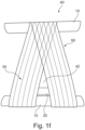
Fig. 1f shows the uniting structure offig. 1e as seen from the side, -
Figs. 1g and 1h show alternative embodiments of the uniting structure offig. 1e , -
Fig. 2a is a perspective view showing a core device used for making the uniting structure offig. 1e , -
Fig. 2b shows the core device offig. 2a mounted onto a rotary device carrying along its length a plurality of spaced apart core devices of the type shown infig. 2a , and -
Figs. 3a-3f show various steps during the making of the uniting structure offig. 1e using the rotary device shown infig. 2b . - The invention will now be explained in more detail by reference to an embodiment, and to a use thereof.
-
Figure 1a is a perspective, partial and schematic view of a three dimensional light-weight carbon fibre structure including carbon fibre upper andlower tubes section 1 of a sprayer boom which is part of an agricultural sprayer. -
Fig. 1b shows, in part, an embodiment of such an agricultural sprayer, which also comprises a tractor driven or carried tank S for containing a liquid spraying agent, the tank S being supported by a frame F, normally provided with supporting wheels, of which only one is shown. The sprayer boom normally comprises two similar parts that extend outwards from a respective side of the frame F. -
Fig. 1b shows one such part of the boom extending from one side of the frame F and which has an outer end E; for convenience, in the following, the shown boom part will simply be referred to as a boom, and be designatednumeral 3. - The
boom 3 shown infig. 1b carries pipes (not shown) connecting the tank S with nozzles N for delivering the spraying agent and being arranged spaced apart along the length of theboom 3. The spraying agent is, as is conventional, delivered from the tank S using a suitable pump (not shown) mounted on the aforementioned frame F. - The shown
boom 3 is, as is conventional for agricultural sprayer booms, supported by the frame F via a link L that allows theboom 3 to be turned into a non-operative position where it extends alongside the tank S in a direction of travel of the agricultural sprayer. Infig. 1b theboom 3 is shown as being formed by two individual sections, one being thesection 1 shown infig. 1a and the other one being a relatively heavy three dimensional metal lattice structure B, or a light weight three dimensional lattice structure B such as of aluminium or carbon, connected at one end to the frame F via the aforementioned link L. The light-weightcarbon fibre section 1 which defines the boom outer end E at its one end, is connected with the metal structure B at its other end via at least one connector device T. - The connector device T is shown highly schematically in
fig. 1c , and is typically a metal body. The connector device T allows for thecarbon fibre section 1 to be supported by the metal structure B, and may itself be configured to allow for the light-weight section 1 to be turned relative to the metal structure B to allow for the twostructures 1, B to be folded against each other, to reduce the overall length of theboom 3 when in its non-operative position alongside the tank S. Often a connector device T will connect the shownupper tube 10 of thesection 1 with an upper lattice member of the metal structure B, while similar connectors will connect each of the shown twolower tubes - Where the
carbon fibre section 1 is connected directly to the frame F, as where no metal structure B is used, the connector device T may comprise, or be connected to, the aforementioned link L at the frame F. The connector device T may be welded to or otherwise secured to the metal structure B or to the frame F, as the case may be. - In
fig. 1d is schematically shown a perspective view of the end portion of an elongated hollow cylindrical carbon fibre tube. Such a tube defines each one of the shownelongated tubes section 1 wherein theupper tube 10 may preferably converge towards the twolower tubes boom 3. - Preferably, the
tubes carbon fibre section 1, or in several parts forming together the full length of thesection 1. - Generally, each
elongated tube carbon fibre string 800 in alternate directions around a mandrel that defines the internal diameter of thetube tube WO99/49150 -
Fig. 1e shows an embodiment of a hollow, uniting carbon fibre/epoxy structure 40 bonded to each of threecarbon fibre tubes carbon fibre section 1 as shown infig. 1a . The unitingstructure 40 is formed in a winding operation by winding a many metres long carbon fibre string with a liquid epoxy coating around portions of thetubes tubes tubes structures 40 define respective tube joints along the length of thesection 1. The aforementioned nozzles N may be carried by one of thelower tubes - The uniting
structure 40 offig. 1e has layeredcarbon fibre legs top tube 10 of thecarbon fibre structure 1, with twoprimary layers leg tube inner one 70 of the two primary layers contacts a portion of eachtube structure 40 while an outer one 80 contacts the remaining portion of eachtube structure 40. In this manner thetubes layers structure 40 to each other but also to bond the unitingstructure 40 to thetubes - As will be understood, each of the shown
primary layers primary layer legs fig. 1e , such that the uniting structure appears as a monolithic structure in the region where the twolegs fig. 1h where the two converginglegs top tube 10. - The
legs lower tubes structure 40, namely in the gap between thelegs lower tubes structure 40 interfering with the spraying pattern. A most narrow part of the gap is shown infig. 1e bynumeral 42. - In another embodiment, as shown in
fig. 1g the unitingstructure 40 does not included spaced apart legs and appears as a single monolithic structure. Theboom sections 1 shown infigs. 1b ,1g and 1h may be 2-dimensional, or 3-diomensional as theboom section 1 shown infig. 1a . - Turning now to
fig. 2a there is shown a perspective view of acore device 100 used for making the uniting structure offigs. 1f-1h , andfig. 2b shows thecore device 100 in a manufacturing facility, mounted onto an elongatedrotating axle 400 carrying along its length a plurality of spaced apartcore devices 100. Thecore device 100 has a through-goingopening 105 for receiving theelongated axle 400, and has on its periphery a number ofelongated recesses core device 100 may also be provided with a projectingarea 102 configured for forming theaforementioned gap 42 in that thecarbon fibre string 800 is not wound onto this projectingarea 102. A slip agent is preferably applied to the surface of thecore device 100 to allow removal therefrom of the finishedunifying structure 40. -
Fig. 2b shows an initial step during the making of theunifying structure 40, more specifically during the winding of the portion of acarbon fibre string 800 forming the innerprimary layer 70. It will be understood that the winding procedure takes place in that theaxle 400 is rotated about its longitudinal axis, thereby rotating thecore device 100 about the same axis while unwinding thecarbon fibre string 800 from a supply W, such as a spool, which rotates also, as indicated by the arrow B infig. 2b . The winding procedure is preferably such that the supply W moves also sideways back and forth in the directions indicated by arrows A infig. 2b . -
Fig. 2b shows also one embodiment of aremovable spacer device 200, the overall purpose of which is to ensure that the innerprimary layer 70 is wound about thecore device 100 with a certain slack where portions of theprimary layer 70 bridge therecesses -
Fig. 3a again shows thecore device 100 operated in a manufacturing facility, and with an alternative spacer device comprising in this case threetubular pieces 200, each to be received in a respective one of the threeelongated recesses tubes tubular pieces 200 are, like thedevice 200 shown infig. 2b , preferably provided with a slip agent, such as Teflon, allowing removal of the spacer device(s) 200 from thecore device 100 once winding of the innerprimary layer 70 around thecore device 100 has been completed. -
Fig. 3b shows thecore device 100 after a number of windings of thecarbon fibre string 800 have been applied to form the innerprimary layer 70, using the facility generally shown infig. 2b . At this point the winding procedure is interrupted and thespacer devices 200 are removed, as shown by the arrow infig. 3c , leaving outwardly bulging portions of the innerprimary layer 70 where thespacer devices 200 were before, and/or spanning across therecesses fig. 2b . Using a tool (not shown) the outwardly bulgingportions 75 of the innerprimary layer 70 is now pressed into therecesses fig. 3d , whereby the innerprimary layer 70 not only contacts acore device 100 periphery part defining the sides of thecore device 100 but also the periphery part defining the bottom of therecesses core device 100. - The prefabricated
carbon fibre tubes structure 1 together with the unifyingstructure 40, are then placed into arespective recess primary layer 70 that previously formed the aforementioned outwardly bulgingportions 75, as shown infig. 3e , and the winding procedure is initiated again to form now the outerprimary layer 80. Ending the process a film may be over-winded to ensure compression of theprimary layers - After curing of the epoxy resin or other polymer matrix, such as for 2-4 hours, the axle (not shown in
figs. 3a-3f ) and the plurality ofcore device 100 each carrying a respectiveunifying structure 40 are then removed, leaving alight weight structure 1 as shown infig. 1a . A subsequent, additional curing may take place, such as by then placing thestructure 1 in an oven for about 24 hours at a temperature of eg. 80°C. - While the invention is discussed herein in the context of agricultural sprayer sections made using carbon fibre tubes, the uniting
structure 40 and the method disclosed herein may also be applied for other tubes made from other types of fibres, or even with metal tubes. - A carbon fibre string as mentioned herein may include carbon fibres STS and Toray T700, or Granoc CN600 using PR102/EM100 epoxy resins from GRM Systems as the matrix.
Claims (10)
- A carbon fibre boom structure (1) for an agricultural sprayer boom (3), said boom structure (1) comprising:- an elongated upper carbon fibre tube (10),- at least one elongated lower carbon fibre tube (15, 20) and- a carbon fibre/resin matrix uniting structure (40) bonded to each of said carbon fibre tubes (10, 15, 20) to hold the tubes (10, 15, 20) in a spaced apart position;the carbon fibre boom structure (1) being characterised in thatsaid uniting structure (40) is formed in a winding operation by applying windings of a carbon fibre string (800) with a liquid resin around portions of said tubes (10, 15, 20),said windings and resin matrix define an inner primary layer (70) and an outer primary layer (80) of said uniting structure (40), wherein a portion (75) of said inner primary layer (70) is bonded to a surface portion of each tube (10, 15, 20) that is oriented towards the inside of the uniting structure (40) while a portion of said outer primary layer (80) is bonded to a remaining surface portion of each tube (10, 15, 20) to completely, or essentially completely, envelope each tube (10, 15, 20) by the said portions of said two primary layers (70, 80).
- The boom structure (1) of claim 1, comprising one upper carbon fibre tube (10) and two lower carbon fibre tubes (15, 20), said two lower carbon fibre tubes (15, 20) optionally extending parallel to one another.
- The boom structure (1) of claim 1 or 2, said primary layers (70, 80) being bonded to each other along portions of said windings between said carbon fibre tubes (10, 15, 20).
- The boom structure (1) according to any of the previous claims, said carbon fibre string (800) being laid out for each winding to cross over portions thereof previously laid out.
- The boom structure (1) according to any of the previous claims, said uniting structure (40) including two opposite pairs of legs (55, 60), the legs (55, 60) of each pair converging towards said upper carbon fibre tube (10) and being spaced apart at said lower tube(s) (15, 20).
- A method of making the boom structure (1) according to any of the previous claims, comprising the steps of:- providing a core device (100) having a periphery with a plurality of elongated recesses (110, 120, 130), each recess (110, 120, 130) configured for receiving one of said tubes (10, 15, 20),- providing a supply (W), such as a spool, of a carbon fibre string (800) with a liquid resin,- positioning one or more spacer devices (200) along said periphery,- winding said carbon fibre string (800) with said liquid resin around said core device with said spacer device(s) (200), to form said inner primary layer (70), with portions (75) of said inner primary layer (70) bridging said elongated recesses (110, 115, 120),- removing said spacer device(s) (200),- pressing said portions (75) of said inner primary layer (70) into said elongated recesses (110, 120, 130),- positioning said tubes (10, 15, 20) in a respective one of said elongated recesses (110, 115, 120), with a first surface portion of each tube (10, 15, 20) bearing against a respective one of said portions (75) of said primary layer (70),- winding said carbon fibre string (800) around said inner primary layer (70) and second surface portions of said tubes (10, 15, 20), to form said outer primary layer,- curing said resin to bond said inner and outer primary layers (70, 80) to each other and to said surface portions of said tubes (10, 15, 20),- before or after said curing removing said core device (100).
- The method of the previous claim, comprising the step of longitudinally displacing said supply (W) back and forth relative to said core device (100) during said winding, for said carbon fibre string to cross over portions thereof previously laid out during said winding.
- The method of claim 6 or 7, wherein said fixture (400) with said core device (100) is rotated for said winding, said carbon fibre string being simultaneously unwound from said supply (W), said carbon fibre string (800) being dipped into said liquid resin to apply a coating thereon.
- The method according to any of claims 6-8, wherein one spacer device (200) is positioning in each of said recesses (110, 120, 130).
- The method according to any of the previous claims 6-9 wherein a slip agent is applied to said spacer device(s) (200) and to said recesses (110, 120, 130).
Applications Claiming Priority (2)
| Application Number | Priority Date | Filing Date | Title |
|---|---|---|---|
| DKPA201970672A DK180480B1 (en) | 2019-10-30 | 2019-10-30 | Carbon fiber construction and a method of forming the carbon fiber construction |
| PCT/EP2020/080287 WO2021083960A1 (en) | 2019-10-30 | 2020-10-28 | A carbon fibre structure, and a method for forming the carbon fibre structure |
Publications (3)
| Publication Number | Publication Date |
|---|---|
| EP4050998A1 EP4050998A1 (en) | 2022-09-07 |
| EP4050998B1 true EP4050998B1 (en) | 2023-08-09 |
| EP4050998C0 EP4050998C0 (en) | 2023-08-09 |
Family
ID=73030145
Family Applications (1)
| Application Number | Title | Priority Date | Filing Date |
|---|---|---|---|
| EP20797762.0A Active EP4050998B1 (en) | 2019-10-30 | 2020-10-28 | A carbon fibre structure, and a method of manufacturing this carbon fibre structure |
Country Status (5)
| Country | Link |
|---|---|
| US (1) | US12279608B2 (en) |
| EP (1) | EP4050998B1 (en) |
| AU (1) | AU2020376514B2 (en) |
| DK (1) | DK180480B1 (en) |
| WO (1) | WO2021083960A1 (en) |
Cited By (1)
| Publication number | Priority date | Publication date | Assignee | Title |
|---|---|---|---|---|
| WO2025176535A1 (en) * | 2024-02-21 | 2025-08-28 | Fft Produktionssysteme Gmbh & Co. Kg | Support component for a device for handling a load, system and method for producing the support component |
Families Citing this family (2)
| Publication number | Priority date | Publication date | Assignee | Title |
|---|---|---|---|---|
| US11919250B2 (en) * | 2021-08-25 | 2024-03-05 | The Boeing Company | Method of assembly of carbon fiber space frames for aerospace structures |
| US20260022530A1 (en) * | 2022-07-26 | 2026-01-22 | Fsc Technologies Inc. | Assembly |
Citations (1)
| Publication number | Priority date | Publication date | Assignee | Title |
|---|---|---|---|---|
| EP2514884B1 (en) * | 2011-04-19 | 2013-10-23 | Lockheed Martin Corporation | Lightweight beam structure |
Family Cites Families (75)
| Publication number | Priority date | Publication date | Assignee | Title |
|---|---|---|---|---|
| US1645060A (en) * | 1925-07-11 | 1927-10-11 | Goodyear Tire & Rubber | Truss construction |
| US2593714A (en) * | 1943-06-30 | 1952-04-22 | Roy H Robinson | Method of making cellular structures |
| US3551237A (en) * | 1967-04-18 | 1970-12-29 | Aerojet General Co | Method of preparing filament-wound open beam structures |
| AU2759167A (en) | 1968-09-23 | 1970-04-09 | JAMES LANDRETH and MILTON EUGENE DOWNING DAVID JAMES HENDRY | Agricultural boom spray |
| US3665670A (en) | 1970-04-28 | 1972-05-30 | Nasa | Low-mass truss structure |
| US3798864A (en) * | 1970-10-16 | 1974-03-26 | Georgii B | Supporting structures and methods of making them |
| CA957712A (en) | 1972-06-30 | 1974-11-12 | Evers And Wall Limited | De-icing spraying apparatus |
| US4137354A (en) * | 1977-03-07 | 1979-01-30 | Mcdonnell Douglas Corporation | Ribbed composite structure and process and apparatus for producing the same |
| US4241117A (en) * | 1979-06-14 | 1980-12-23 | The United States Of America As Represented By The Secretary Of The Army | Structural cores and their fabrication |
| US4566247A (en) * | 1983-08-03 | 1986-01-28 | Overbo Gordon I | Captive column |
| US4539785A (en) * | 1983-08-03 | 1985-09-10 | Overbo Gordon I | Captive column |
| US4711398A (en) * | 1985-02-12 | 1987-12-08 | E. Allman & Company Limited | Spraying equipment |
| US4695342A (en) * | 1985-03-28 | 1987-09-22 | General Motors Corporation | Method of forming truck cab frames |
| FR2595270B1 (en) | 1986-03-07 | 1989-03-03 | Evrard Ets | AGRICULTURAL SPRAYING RAMP |
| FR2622579B1 (en) | 1987-11-04 | 1990-03-02 | Hoechst France | ACRYLOYLAMINO-2 METHOXY-2 PURE CRYSTALLIZED METHYL ACETATE AND PROCESS FOR OBTAINING SAME |
| US4880160A (en) | 1988-05-24 | 1989-11-14 | Deere & Company | Torsional link boom suspension for reducing unwanted boom motion |
| FR2643831B1 (en) | 1989-03-03 | 1991-10-18 | Evrard Ets | IMPROVEMENTS ON SPRAYER RAMPS, ESPECIALLY IN AGRICULTURE |
| FR2662579B1 (en) * | 1990-05-31 | 1993-10-22 | Guy Pommier | SPRAY RAMP FOR MOBILE MACHINE. |
| US5310115A (en) | 1991-12-06 | 1994-05-10 | The Broyhill Company | Sprayer having a folding boom |
| US5332178A (en) * | 1992-06-05 | 1994-07-26 | Williams International Corporation | Composite wing and manufacturing process thereof |
| DK139693D0 (en) * | 1993-12-17 | 1993-12-17 | Hardi Int As | AIR CONDITION FOR AN AGRICULTURAL SPRAY |
| DE19527197A1 (en) * | 1995-07-26 | 1997-01-30 | Henrik Schaefer | Workpiece made of a fibre laminate material esp. a laminate embedded in plastic - consists of a number of struts connected to each other contg. fibres |
| FR2744786B1 (en) | 1996-02-09 | 1998-03-27 | Tecnoma | JOINT ASSEMBLY COMPRISING DIRECT CONNECTIONS BETWEEN BEAMS |
| US5992759A (en) | 1998-02-09 | 1999-11-30 | Macdon Industries Ltd. | Material spreader attachment for mounting on a tractor |
| GB2335669B (en) | 1998-03-26 | 2002-08-28 | Philip Rudolph Enos | Structural truss |
| US6082068A (en) * | 1998-10-09 | 2000-07-04 | Tomcat Global Corporation | Method and apparatus for assembling a lightweight stackable truss |
| US20030064187A1 (en) * | 2000-03-18 | 2003-04-03 | Robert Blanchette | Carbon fiber mast |
| US20020026765A1 (en) * | 2000-07-13 | 2002-03-07 | Vahey Michael J. | Structural members |
| IL154130A0 (en) * | 2000-07-28 | 2003-07-31 | Univ Brigham Young | Iso-truss structure |
| US6837446B1 (en) | 2003-01-16 | 2005-01-04 | Sprayer Specialties, Inc. | Unitary boom structure |
| FR2853207B1 (en) | 2003-04-07 | 2005-05-20 | Centre Nat Machinisme Agricole | SPRAY RAMP |
| US6966501B2 (en) * | 2003-05-27 | 2005-11-22 | Deere & Company | Agricultural boom structure |
| USD511875S1 (en) | 2003-05-27 | 2005-11-22 | Deere & Company | Agricultural boom section |
| DE10338380A1 (en) | 2003-08-21 | 2005-03-17 | Amazonen-Werke H. Dreyer Gmbh & Co. Kg | Transfer linkage for spreader machines etc has folding side booms consisting of segment parts with each two outer segment parts made as aluminium stays and connected through steel articulation joints |
| US7694486B2 (en) * | 2003-12-12 | 2010-04-13 | Alliant Techsystems Inc. | Deployable truss having second order augmentation |
| GB0426944D0 (en) * | 2004-12-08 | 2005-01-12 | Airbus Uk Ltd | A trussed structure |
| AR048007A1 (en) * | 2005-03-11 | 2006-03-15 | Caiman Soc De Responsabilidad | BARREL STRUCTURE, BOTTLE FOR AGRICULTURAL SPRAYING COMPOSED BY THE BARREL AND BARREL MANUFACTURING METHOD |
| CZ17125U1 (en) | 2006-10-31 | 2007-01-02 | Akp Spol. S R. O. | Arm of liquid-spraying apparatus |
| EP2335138A4 (en) * | 2008-08-15 | 2012-12-19 | Qualcomm Inc | Enhanced multi-touch detection |
| DE102009059111B9 (en) | 2009-12-18 | 2015-01-15 | Carbofibretec Gmbh | Vertically pivotable field sprayer with horizontally pivotable segments |
| JP6076918B2 (en) * | 2011-03-04 | 2017-02-08 | ブロックウェル,マイケル,イアン | Structural member with energy absorption effect under tension on the outside |
| WO2012149516A1 (en) | 2011-04-28 | 2012-11-01 | Agco Corporation | Modular agricultural boom structure |
| US8939383B2 (en) | 2011-04-29 | 2015-01-27 | Cnh Industrial America Llc | Adhesively bonded frame section for agricultural sprayer boom |
| US20140182232A1 (en) * | 2011-05-19 | 2014-07-03 | Drew Ryan Holt | Composite open/spaced matrix composite support structures and methods of making and using thereof |
| US8746589B2 (en) | 2011-09-09 | 2014-06-10 | Deere & Company | Boom assembly joints |
| US8646702B2 (en) | 2011-10-13 | 2014-02-11 | Deere & Company | Boom fold structure |
| GB201122306D0 (en) | 2011-12-23 | 2012-02-01 | Agco Netherlands Bv | Modular sprayer boom construction |
| US9404249B2 (en) * | 2012-01-18 | 2016-08-02 | Adc Acquisition Company | Ultra light fiber placed truss |
| US8859088B2 (en) * | 2012-04-16 | 2014-10-14 | Auburn University | Minimal weight composites using open structure |
| US9435060B2 (en) * | 2012-05-01 | 2016-09-06 | University Of Maryland | Continuous wound composite truss structures |
| US9848592B2 (en) | 2013-06-12 | 2017-12-26 | Specialty Enterprises, Llc | Agricultural spray boom |
| CA2841022A1 (en) | 2013-06-12 | 2014-12-12 | Specialty Enterprises, Llc | Agricultural spray boom |
| BR112016010380B1 (en) | 2013-11-08 | 2019-08-13 | King Agro Europa S.L. | support for a spray boom for an agricultural sprayer |
| US9462799B2 (en) | 2013-12-18 | 2016-10-11 | Agco Corporation | Pivot hinge boom spray system |
| US9839211B2 (en) | 2014-08-11 | 2017-12-12 | Deere & Company | Segmented boom system for work vehicle |
| US9925554B2 (en) | 2014-10-31 | 2018-03-27 | Claussen Technology, Inc. | Sprayer apparatus and systems |
| DE102014222933B4 (en) * | 2014-11-11 | 2021-09-09 | Bayerische Motoren Werke Aktiengesellschaft | Fiber composite component and method for producing a fiber composite component |
| USD753729S1 (en) | 2015-03-09 | 2016-04-12 | King Marine, S.A. | Boom arm for agricultural sprayer |
| US10258028B2 (en) | 2015-04-27 | 2019-04-16 | Cnh Industrial America Llc | Sprayer boom with perforated outer walls |
| DE102015110696A1 (en) | 2015-07-02 | 2017-01-05 | Carbofibretec Gmbh | Field sprayer and sprayer arm in mixed construction |
| US20170216871A1 (en) * | 2016-02-01 | 2017-08-03 | Specialty Enterprises, Llc | Boom Constructed from Several Shaped Panels of Material |
| AU2016219741B2 (en) * | 2016-08-29 | 2022-09-15 | The Boeing Company | A method and system for fabricating a composite structure |
| US10180000B2 (en) * | 2017-03-06 | 2019-01-15 | Isotruss Industries Llc | Composite lattice beam |
| FR3064156B1 (en) | 2017-03-23 | 2021-09-03 | Kuhn Audureau Sa | SPRAYING OR SPREADING RAMP STRUCTURE AND MACHINE INCLUDING SUCH STRUCTURE |
| JP6737244B2 (en) | 2017-06-28 | 2020-08-05 | 井関農機株式会社 | Work vehicle |
| CZ307704B6 (en) | 2017-07-18 | 2019-02-27 | AGRIO MZS s.r.o. | Arm of an agricultural sprinkler |
| US10806105B2 (en) | 2017-10-04 | 2020-10-20 | Deere & Company | System of integrated passageways in a carbon fiber boom and method thereof |
| US10645916B2 (en) | 2017-10-04 | 2020-05-12 | Deere & Company | Integrated lighting system in a carbon fiber boom and method thereof |
| FR3078863B1 (en) | 2018-03-19 | 2020-03-06 | Kuhn-Audureau Sa | SPRAYING OR SPREADING RAMP STRUCTURE AND SPRAYER OR SPREADER WITH SUCH A RAMP |
| US11369105B2 (en) * | 2018-05-22 | 2022-06-28 | Bk Components S.A. | Support for spreading boom of an agricultural sprayer |
| WO2019234625A1 (en) * | 2018-06-04 | 2019-12-12 | Conseil Et Technique | Method for manufacturing a part made from composite material |
| DE102018210119A1 (en) * | 2018-06-21 | 2019-12-24 | Bayerische Motoren Werke Aktiengesellschaft | Fiber composite body and method for producing a fiber composite body |
| US11737447B2 (en) * | 2019-06-13 | 2023-08-29 | Cnh Industrial America Llc | Inverted truss geometry for agricultural spray boom |
| US11766036B2 (en) * | 2019-08-21 | 2023-09-26 | Cnh Industrial America Llc | Agricultural vehicle having an improved application boom for supporting an application system |
| GB201913473D0 (en) * | 2019-09-18 | 2019-10-30 | Agco Do Brazil Maqu E Equipmentos | Boom for an agricultural crop sprayer and method of manufacture |
-
2019
- 2019-10-30 DK DKPA201970672A patent/DK180480B1/en active IP Right Grant
-
2020
- 2020-10-28 AU AU2020376514A patent/AU2020376514B2/en active Active
- 2020-10-28 US US17/772,889 patent/US12279608B2/en active Active
- 2020-10-28 WO PCT/EP2020/080287 patent/WO2021083960A1/en not_active Ceased
- 2020-10-28 EP EP20797762.0A patent/EP4050998B1/en active Active
Patent Citations (1)
| Publication number | Priority date | Publication date | Assignee | Title |
|---|---|---|---|---|
| EP2514884B1 (en) * | 2011-04-19 | 2013-10-23 | Lockheed Martin Corporation | Lightweight beam structure |
Cited By (1)
| Publication number | Priority date | Publication date | Assignee | Title |
|---|---|---|---|---|
| WO2025176535A1 (en) * | 2024-02-21 | 2025-08-28 | Fft Produktionssysteme Gmbh & Co. Kg | Support component for a device for handling a load, system and method for producing the support component |
Also Published As
| Publication number | Publication date |
|---|---|
| DK180480B1 (en) | 2021-05-20 |
| US20220408714A1 (en) | 2022-12-29 |
| EP4050998C0 (en) | 2023-08-09 |
| US12279608B2 (en) | 2025-04-22 |
| AU2020376514A1 (en) | 2022-05-19 |
| EP4050998A1 (en) | 2022-09-07 |
| AU2020376514B2 (en) | 2025-11-27 |
| DK201970672A1 (en) | 2021-05-20 |
| WO2021083960A1 (en) | 2021-05-06 |
Similar Documents
| Publication | Publication Date | Title |
|---|---|---|
| US12279608B2 (en) | Carbon fiber structure, and a method for forming the carbon fiber structure | |
| EP3444512B1 (en) | Construction of pipes | |
| US4172175A (en) | Pole construction | |
| CN102438814B (en) | Composite structure element is connected to the method for pipe | |
| EP0357710B1 (en) | Storage tanks with fabricated support ribs | |
| US8114241B2 (en) | Method for applying a vacuum bag around a fuselage barrel made of composite material to be polymerized | |
| KR101948367B1 (en) | Construction of pipes | |
| US4106797A (en) | Reinforced fitting construction | |
| CN106825109B (en) | The processing unit (plant) of thin-wall barrel | |
| JP2009533221A5 (en) | ||
| FR2720795A1 (en) | Straight bars for transmitting longitudinal forces based on reinforced composite materials. | |
| EP2675732B1 (en) | Belted toroid pressure vessel and method for making the same | |
| EP0647751A2 (en) | Braided airbeams and method of making the same | |
| EP0610037A1 (en) | A joint type fishing rod and method of manufacturing the same | |
| JP5715232B2 (en) | Method for manufacturing an arm with a composite material comprising a transverse bearing configured to receive a fixed or rotating shaft | |
| DK180510B1 (en) | A connector body, a structure comprising the connector body, and a method of forming the structure | |
| EP3822065B1 (en) | Method for manufacturing root segment sections for a root segment of a turbine blade, method for manufacturing the root segment and method for manufacturing the turbine blade | |
| JP2001520945A (en) | Method for manufacturing a metal end of a composite elongated tube | |
| JPH01215199A (en) | Manufacture of bobbin for voice coil | |
| CA1050713A (en) | Method of manufacturing large diameter tubular structures | |
| CN118019633A (en) | Method for manufacturing at least a portion of a wind turbine blade, wind turbine blade portion and wind turbine | |
| CN119185752A (en) | Support for assisting balloon catheter in rewinding and balloon catheter and manufacturing method thereof | |
| JPS637935B2 (en) | ||
| JP3913805B2 (en) | Golf club shaft manufacturing method |
Legal Events
| Date | Code | Title | Description |
|---|---|---|---|
| STAA | Information on the status of an ep patent application or granted ep patent |
Free format text: STATUS: UNKNOWN |
|
| STAA | Information on the status of an ep patent application or granted ep patent |
Free format text: STATUS: THE INTERNATIONAL PUBLICATION HAS BEEN MADE |
|
| PUAI | Public reference made under article 153(3) epc to a published international application that has entered the european phase |
Free format text: ORIGINAL CODE: 0009012 |
|
| STAA | Information on the status of an ep patent application or granted ep patent |
Free format text: STATUS: REQUEST FOR EXAMINATION WAS MADE |
|
| 17P | Request for examination filed |
Effective date: 20220506 |
|
| AK | Designated contracting states |
Kind code of ref document: A1 Designated state(s): AL AT BE BG CH CY CZ DE DK EE ES FI FR GB GR HR HU IE IS IT LI LT LU LV MC MK MT NL NO PL PT RO RS SE SI SK SM TR |
|
| DAV | Request for validation of the european patent (deleted) | ||
| DAX | Request for extension of the european patent (deleted) | ||
| GRAP | Despatch of communication of intention to grant a patent |
Free format text: ORIGINAL CODE: EPIDOSNIGR1 |
|
| STAA | Information on the status of an ep patent application or granted ep patent |
Free format text: STATUS: GRANT OF PATENT IS INTENDED |
|
| INTG | Intention to grant announced |
Effective date: 20230316 |
|
| GRAS | Grant fee paid |
Free format text: ORIGINAL CODE: EPIDOSNIGR3 |
|
| GRAA | (expected) grant |
Free format text: ORIGINAL CODE: 0009210 |
|
| STAA | Information on the status of an ep patent application or granted ep patent |
Free format text: STATUS: THE PATENT HAS BEEN GRANTED |
|
| AK | Designated contracting states |
Kind code of ref document: B1 Designated state(s): AL AT BE BG CH CY CZ DE DK EE ES FI FR GB GR HR HU IE IS IT LI LT LU LV MC MK MT NL NO PL PT RO RS SE SI SK SM TR |
|
| REG | Reference to a national code |
Ref country code: GB Ref legal event code: FG4D |
|
| REG | Reference to a national code |
Ref country code: CH Ref legal event code: EP |
|
| REG | Reference to a national code |
Ref country code: DE Ref legal event code: R096 Ref document number: 602020015579 Country of ref document: DE |
|
| REG | Reference to a national code |
Ref country code: IE Ref legal event code: FG4D |
|
| U01 | Request for unitary effect filed |
Effective date: 20230906 |
|
| U07 | Unitary effect registered |
Designated state(s): AT BE BG DE DK EE FI FR IT LT LU LV MT NL PT SE SI Effective date: 20230913 |
|
| U20 | Renewal fee for the european patent with unitary effect paid |
Year of fee payment: 4 Effective date: 20231024 |
|
| PG25 | Lapsed in a contracting state [announced via postgrant information from national office to epo] |
Ref country code: GR Free format text: LAPSE BECAUSE OF FAILURE TO SUBMIT A TRANSLATION OF THE DESCRIPTION OR TO PAY THE FEE WITHIN THE PRESCRIBED TIME-LIMIT Effective date: 20231110 |
|
| PGFP | Annual fee paid to national office [announced via postgrant information from national office to epo] |
Ref country code: ES Payment date: 20231124 Year of fee payment: 4 |
|
| PG25 | Lapsed in a contracting state [announced via postgrant information from national office to epo] |
Ref country code: IS Free format text: LAPSE BECAUSE OF FAILURE TO SUBMIT A TRANSLATION OF THE DESCRIPTION OR TO PAY THE FEE WITHIN THE PRESCRIBED TIME-LIMIT Effective date: 20231209 |
|
| PG25 | Lapsed in a contracting state [announced via postgrant information from national office to epo] |
Ref country code: RS Free format text: LAPSE BECAUSE OF FAILURE TO SUBMIT A TRANSLATION OF THE DESCRIPTION OR TO PAY THE FEE WITHIN THE PRESCRIBED TIME-LIMIT Effective date: 20230809 Ref country code: NO Free format text: LAPSE BECAUSE OF FAILURE TO SUBMIT A TRANSLATION OF THE DESCRIPTION OR TO PAY THE FEE WITHIN THE PRESCRIBED TIME-LIMIT Effective date: 20231109 Ref country code: IS Free format text: LAPSE BECAUSE OF FAILURE TO SUBMIT A TRANSLATION OF THE DESCRIPTION OR TO PAY THE FEE WITHIN THE PRESCRIBED TIME-LIMIT Effective date: 20231209 Ref country code: HR Free format text: LAPSE BECAUSE OF FAILURE TO SUBMIT A TRANSLATION OF THE DESCRIPTION OR TO PAY THE FEE WITHIN THE PRESCRIBED TIME-LIMIT Effective date: 20230809 Ref country code: GR Free format text: LAPSE BECAUSE OF FAILURE TO SUBMIT A TRANSLATION OF THE DESCRIPTION OR TO PAY THE FEE WITHIN THE PRESCRIBED TIME-LIMIT Effective date: 20231110 |
|
| PG25 | Lapsed in a contracting state [announced via postgrant information from national office to epo] |
Ref country code: PL Free format text: LAPSE BECAUSE OF FAILURE TO SUBMIT A TRANSLATION OF THE DESCRIPTION OR TO PAY THE FEE WITHIN THE PRESCRIBED TIME-LIMIT Effective date: 20230809 |
|
| PG25 | Lapsed in a contracting state [announced via postgrant information from national office to epo] |
Ref country code: ES Free format text: LAPSE BECAUSE OF FAILURE TO SUBMIT A TRANSLATION OF THE DESCRIPTION OR TO PAY THE FEE WITHIN THE PRESCRIBED TIME-LIMIT Effective date: 20230809 |
|
| PG25 | Lapsed in a contracting state [announced via postgrant information from national office to epo] |
Ref country code: SM Free format text: LAPSE BECAUSE OF FAILURE TO SUBMIT A TRANSLATION OF THE DESCRIPTION OR TO PAY THE FEE WITHIN THE PRESCRIBED TIME-LIMIT Effective date: 20230809 Ref country code: RO Free format text: LAPSE BECAUSE OF FAILURE TO SUBMIT A TRANSLATION OF THE DESCRIPTION OR TO PAY THE FEE WITHIN THE PRESCRIBED TIME-LIMIT Effective date: 20230809 Ref country code: ES Free format text: LAPSE BECAUSE OF FAILURE TO SUBMIT A TRANSLATION OF THE DESCRIPTION OR TO PAY THE FEE WITHIN THE PRESCRIBED TIME-LIMIT Effective date: 20230809 Ref country code: CZ Free format text: LAPSE BECAUSE OF FAILURE TO SUBMIT A TRANSLATION OF THE DESCRIPTION OR TO PAY THE FEE WITHIN THE PRESCRIBED TIME-LIMIT Effective date: 20230809 Ref country code: SK Free format text: LAPSE BECAUSE OF FAILURE TO SUBMIT A TRANSLATION OF THE DESCRIPTION OR TO PAY THE FEE WITHIN THE PRESCRIBED TIME-LIMIT Effective date: 20230809 |
|
| REG | Reference to a national code |
Ref country code: DE Ref legal event code: R097 Ref document number: 602020015579 Country of ref document: DE |
|
| PG25 | Lapsed in a contracting state [announced via postgrant information from national office to epo] |
Ref country code: MC Free format text: LAPSE BECAUSE OF FAILURE TO SUBMIT A TRANSLATION OF THE DESCRIPTION OR TO PAY THE FEE WITHIN THE PRESCRIBED TIME-LIMIT Effective date: 20230809 |
|
| REG | Reference to a national code |
Ref country code: CH Ref legal event code: PL |
|
| PLBE | No opposition filed within time limit |
Free format text: ORIGINAL CODE: 0009261 |
|
| STAA | Information on the status of an ep patent application or granted ep patent |
Free format text: STATUS: NO OPPOSITION FILED WITHIN TIME LIMIT |
|
| 26N | No opposition filed |
Effective date: 20240513 |
|
| PG25 | Lapsed in a contracting state [announced via postgrant information from national office to epo] |
Ref country code: CH Free format text: LAPSE BECAUSE OF NON-PAYMENT OF DUE FEES Effective date: 20231031 |
|
| PG25 | Lapsed in a contracting state [announced via postgrant information from national office to epo] |
Ref country code: CH Free format text: LAPSE BECAUSE OF NON-PAYMENT OF DUE FEES Effective date: 20231031 |
|
| PG25 | Lapsed in a contracting state [announced via postgrant information from national office to epo] |
Ref country code: IE Free format text: LAPSE BECAUSE OF NON-PAYMENT OF DUE FEES Effective date: 20231028 |
|
| PG25 | Lapsed in a contracting state [announced via postgrant information from national office to epo] |
Ref country code: IE Free format text: LAPSE BECAUSE OF NON-PAYMENT OF DUE FEES Effective date: 20231028 |
|
| U20 | Renewal fee for the european patent with unitary effect paid |
Year of fee payment: 5 Effective date: 20240927 |
|
| PG25 | Lapsed in a contracting state [announced via postgrant information from national office to epo] |
Ref country code: CY Free format text: LAPSE BECAUSE OF FAILURE TO SUBMIT A TRANSLATION OF THE DESCRIPTION OR TO PAY THE FEE WITHIN THE PRESCRIBED TIME-LIMIT; INVALID AB INITIO Effective date: 20201028 |
|
| PG25 | Lapsed in a contracting state [announced via postgrant information from national office to epo] |
Ref country code: HU Free format text: LAPSE BECAUSE OF FAILURE TO SUBMIT A TRANSLATION OF THE DESCRIPTION OR TO PAY THE FEE WITHIN THE PRESCRIBED TIME-LIMIT; INVALID AB INITIO Effective date: 20201028 |
|
| U20 | Renewal fee for the european patent with unitary effect paid |
Year of fee payment: 6 Effective date: 20250926 |
|
| PG25 | Lapsed in a contracting state [announced via postgrant information from national office to epo] |
Ref country code: TR Free format text: LAPSE BECAUSE OF FAILURE TO SUBMIT A TRANSLATION OF THE DESCRIPTION OR TO PAY THE FEE WITHIN THE PRESCRIBED TIME-LIMIT Effective date: 20230809 |
|
| PGFP | Annual fee paid to national office [announced via postgrant information from national office to epo] |
Ref country code: GB Payment date: 20251023 Year of fee payment: 6 |