EP4050864B1 - Verfahren zur darstellung von objekten eines netzwerks in einer graphischen benutzerschnittstelle - Google Patents
Verfahren zur darstellung von objekten eines netzwerks in einer graphischen benutzerschnittstelle Download PDFInfo
- Publication number
- EP4050864B1 EP4050864B1 EP22158683.7A EP22158683A EP4050864B1 EP 4050864 B1 EP4050864 B1 EP 4050864B1 EP 22158683 A EP22158683 A EP 22158683A EP 4050864 B1 EP4050864 B1 EP 4050864B1
- Authority
- EP
- European Patent Office
- Prior art keywords
- square
- level
- squares
- nodes
- forces
- Prior art date
- Legal status (The legal status is an assumption and is not a legal conclusion. Google has not performed a legal analysis and makes no representation as to the accuracy of the status listed.)
- Active
Links
Images

Classifications
-
- G—PHYSICS
- G06—COMPUTING OR CALCULATING; COUNTING
- G06F—ELECTRIC DIGITAL DATA PROCESSING
- G06F8/00—Arrangements for software engineering
- G06F8/20—Software design
- G06F8/24—Object-oriented
-
- G—PHYSICS
- G06—COMPUTING OR CALCULATING; COUNTING
- G06F—ELECTRIC DIGITAL DATA PROCESSING
- G06F9/00—Arrangements for program control, e.g. control units
- G06F9/06—Arrangements for program control, e.g. control units using stored programs, i.e. using an internal store of processing equipment to receive or retain programs
- G06F9/46—Multiprogramming arrangements
- G06F9/50—Allocation of resources, e.g. of the central processing unit [CPU]
- G06F9/5061—Partitioning or combining of resources
-
- H—ELECTRICITY
- H04—ELECTRIC COMMUNICATION TECHNIQUE
- H04L—TRANSMISSION OF DIGITAL INFORMATION, e.g. TELEGRAPHIC COMMUNICATION
- H04L41/00—Arrangements for maintenance, administration or management of data switching networks, e.g. of packet switching networks
- H04L41/22—Arrangements for maintenance, administration or management of data switching networks, e.g. of packet switching networks comprising specially adapted graphical user interfaces [GUI]
-
- G—PHYSICS
- G06—COMPUTING OR CALCULATING; COUNTING
- G06F—ELECTRIC DIGITAL DATA PROCESSING
- G06F3/00—Input arrangements for transferring data to be processed into a form capable of being handled by the computer; Output arrangements for transferring data from processing unit to output unit, e.g. interface arrangements
- G06F3/01—Input arrangements or combined input and output arrangements for interaction between user and computer
- G06F3/048—Interaction techniques based on graphical user interfaces [GUI]
-
- G—PHYSICS
- G06—COMPUTING OR CALCULATING; COUNTING
- G06F—ELECTRIC DIGITAL DATA PROCESSING
- G06F9/00—Arrangements for program control, e.g. control units
- G06F9/06—Arrangements for program control, e.g. control units using stored programs, i.e. using an internal store of processing equipment to receive or retain programs
- G06F9/44—Arrangements for executing specific programs
- G06F9/451—Execution arrangements for user interfaces
-
- H—ELECTRICITY
- H04—ELECTRIC COMMUNICATION TECHNIQUE
- H04L—TRANSMISSION OF DIGITAL INFORMATION, e.g. TELEGRAPHIC COMMUNICATION
- H04L41/00—Arrangements for maintenance, administration or management of data switching networks, e.g. of packet switching networks
- H04L41/12—Discovery or management of network topologies
-
- H—ELECTRICITY
- H04—ELECTRIC COMMUNICATION TECHNIQUE
- H04L—TRANSMISSION OF DIGITAL INFORMATION, e.g. TELEGRAPHIC COMMUNICATION
- H04L41/00—Arrangements for maintenance, administration or management of data switching networks, e.g. of packet switching networks
- H04L41/14—Network analysis or design
- H04L41/145—Network analysis or design involving simulating, designing, planning or modelling of a network
-
- H—ELECTRICITY
- H04—ELECTRIC COMMUNICATION TECHNIQUE
- H04L—TRANSMISSION OF DIGITAL INFORMATION, e.g. TELEGRAPHIC COMMUNICATION
- H04L43/00—Arrangements for monitoring or testing data switching networks
- H04L43/04—Processing captured monitoring data, e.g. for logfile generation
- H04L43/045—Processing captured monitoring data, e.g. for logfile generation for graphical visualisation of monitoring data
-
- H—ELECTRICITY
- H04—ELECTRIC COMMUNICATION TECHNIQUE
- H04L—TRANSMISSION OF DIGITAL INFORMATION, e.g. TELEGRAPHIC COMMUNICATION
- H04L41/00—Arrangements for maintenance, administration or management of data switching networks, e.g. of packet switching networks
- H04L41/08—Configuration management of networks or network elements
- H04L41/0893—Assignment of logical groups to network elements
Definitions
- the present invention relates to the field of graphic user interface (GUI).
- GUI graphic user interface
- the present invention relates to a method for representing objects of a network in a GUI.
- GUI graphical user interface
- Designing the visual composition and temporal behavior of a GUI is an important part of software application programming in the area of human-computer interaction. Its goal is to enhance the efficiency and ease of use for the underlying logical design of a stored program, while the actions in a GUI are usually performed through direct manipulation of the graphical elements.
- GUI usually refers to the visible graphical interface features of an application. Users may interact with information by manipulating visual widgets that allow for interactions appropriate to the kind of data they hold. The widgets of a well-designed interface are selected to support the actions necessary to achieve the goals of users.
- a kind of GUI employed to ensure a proper network visibility is the network graph, wherein each computer or device in the network is represented as a node, and the communications among them are represented as links that connects the nodes.
- a network graph in order to have a clear visualisation of all components, there is the need to dispose the nodes in such a way to be well spaced to each other, wherein the nodes that are directly connected by a link should be placed closed to each other and if a new node or link appears in a new iteration the position of other nodes should not change in a substantive way.
- a well-known approach to compute the node positions such as to fit the above properties is to use a pseudo-physical simulation.
- Each node is treated as a point particle with a given mass (m), and generate a pseudo-gravitational repulsive force that acts on all other nodes.
- Each link is treated as a spring with a given elastic constant that attract connected nodes.
- the European Patent Application no. EP3333735A1 describes a method and computer program for determining a placement of at least one circuit for a reconfigurable logic device. The method comprises calculating a circuit graph based on the information related to the at least one circuit.
- the circuit graph comprises a plurality of nodes and a plurality of edges.
- the plurality of nodes represent at least a subset of the plurality of blocks of the at least one circuit and wherein the plurality of edges represent at least a subset of the plurality of connections between the plurality of blocks of the at least one circuit.
- the method further comprises determining a force-directed layout of the circuit graph.
- the force-directed layout is based on attractive forces based on the plurality of connections between the plurality of blocks and based on repulsive forces between the plurality of blocks.
- the method further comprises determining a placement of the plurality of logic blocks onto a plurality of available logic cells of the reconfigurable logic device based on the force-directed layout of the circuit graph
- a naive approach to evaluate the gravitational forces consists in iterating, for each node ( i ), on all the other nodes ( j ) and compute the force that each of the other node ( j ) generates on the node (i).
- the node ( i ) for which the force is to be computed is considered as the receiver that receives the forces produced on it by all the other nodes that act as sources.
- This approach has a complexity of order O(N 2 ) (being N the number of nodes) and cannot be applied in realistic cases since as soon as N increase it requires far too much resources in each iteration.
- each force calculation require the evaluation of power, square root and trigonometric functions, and so is computationally expensive, therefore it is important to try to reduce as much as possible the number of force evaluations required.
- a further approach which moves towards the aforementioned need, is the Barnes-Hut method that permits to reduce the complexity to O(N*Log(N)).
- the central idea of this method is still to iterate on each receiver but putting together several sources considering them as a single source. In this way for each group of sources assembled together, a single evaluation of the gravitational force is required, instead of having a single evaluation for each node of the group.
- the Barnes-Hut method reduces the complexity by removing the iteration on each of the sources and replacing with an iteration on a group of sources. In this way several source masses that are close enough, can possibly be considered as a single mass, reducing therefore the number of force evaluation required.
- each source, or mass can be interpreted both as a source and as a receiver, therefore the overall calculation requires to perform a double nested iteration, with a great amount of computational resources required.
- the object of the present invention is to provide a method for representing objects and their network connection capable of minimizing the aforementioned drawbacks.
- the present invention relates to method for representing objects of a network in a GUI.
- the method according to the present invention finds a useful application in any kind of physical infrastructures or automation systems connected in a network, in particular in industrial automation systems, such as industrial processes for manufacturing production, industrial processes for power generation, infrastructures for distribution of fluids (water, oil and gas), infrastructures for the generation and/or transmission of electric power, infrastructures for transport management. Moreover, it finds useful application with all the technology environments, including Information Technology (IT), Operation Technology (OT) and Internet of Things (IoT).
- IT Information Technology
- OT Operation Technology
- IoT Internet of Things
- each mass can be interpreted both as a source and as a receiver.
- the mass itself can be considered as a receiver and all the other masses are the sources that generate a force on the receiver.
- the overall calculation requires therefore to perform a double nested iteration.
- the method according to the present invention reduces the complexity by removing the iteration on each node putting together either the sources and the receivers when evaluating the forces. In this way several source masses that are close enough, can possibly be considered as a single mass, reducing therefore the number of force evaluation required. At same time, several receiver masses that are close enough, can possibly be considered as a single mass, further reducing the number of force evaluation required.
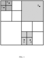
- Figure 1 illustrates a first example, to be processed according to the method of the present invention, which comprises five nodes numbered from 1 to 5. These nodes represent corresponding objects in a network.
- the node numbered as 1 requires three forces evaluation (node numbered as 2, group of node numbered as 3 and node numbered as 4, node numbered as 5)
- the node numbered as 2 requires three forces evaluation (node numbered as 1, group of node numbered as 3 and node numbered as 4, node numbered as 5)
- the node numbered as 3 requires three forces evaluation (group of node numbered as 1 and node numbered as 2, node numbered as 4, node numbered as 5)
- the node numbered as 4 requires three forces evaluation (group of node numbered as 1 and node numbered as 2, node numbered as 3, node numbered as 5)
- the node numbered as 5 requires two forces evaluation (group of node numbered as 1 and node numbered as 2, group of node numbered as 1 and node numbered as 2). Resulting in a complexity of sixteen forces evaluation.
- the method for representing objects of a network in a GUI according to the present invention allows to reduce more the complexity just to ten forces evaluation.
- the method comprises first allocating all of the objects of the network as respective nodes in a two-dimensional space.
- Figure 1 illustrates such allocation that will be described in greater details in the following.
- the allocating comprises defining, by a computerized data processing unit, the random initial position of all of the nodes assigning to each of the nodes the respective coordinates along the x and y axes in the two-dimensional space. Subsequently, enclosing, by the computerized data processing unit, all of the nodes in a single base square, as represented in the edges of Figure 1 .
- the single base square is approached by dividing it in a plurality of 1 st -level squares, again by a computerized data processing unit.
- a plurality of 1 st -level squares consists of four squares having the same dimensions.
- the 1 st -level squares are nested in the base square so that they represent children of the same.
- the allocating comprises subdividing, by the computerized data processing unit, each of the 1 st -level squares in a plurality of 2 nd -level squares, wherein the subdividing is made for the 1 st -level squares provided with two or more of the nodes.
- a plurality of 2 nd -level squares consists of four squares having the same dimensions.
- each child square is defined by a number based on the position with respect to the parent square, wherein notation 1 defines the square in the top left position, notation 2 defines the square in the top right position, the notation 3 defines the square in the bottom right position and notation 4 defines the square in the bottom left position.
- the notation of the parent squares will be maintained at each level. Therefore, the 1 st -level squares are identified with the notation 1, 2, 3 and 4 starting with the 1 st -level squares on the top left going clockwise towards bottom left.
- square 2 and square 4 will not be subdivided anymore, since the first one contains just a single node, i.e. node numbered as 5, while the second one contains no nodes.
- each of the square 1 and square 3 will be subdivided, as described, in four more 2 nd -level squares having the same dimensions.
- the 2 nd -level squares are nested in the respective 1 st -level squares so that they represent children of the same.
- the 2 nd -level squares are identified with the notation 1-1, 1-2, 1-3 and 1-4, for the 1 st -level square with the notation 1, and with the notation 3-1, 3-2, 3-3, 3-4, for the 1 st -level square with the notation 3, again starting with the 2 nd -level squares on the top left going clockwise towards bottom left.
- the nodes being enclosed in the 2 nd -level square with the notation 1-1, i.e. nodes numbered as 1 and 2, and in the 2 nd -level square with the notation 3-4, i.e. nodes numbered as 3 and 4.
- each of the (n) th -level squares is subdivided in a plurality of (n+1) th -level squares, and the iteration is done until the (n) th -level squares are provided with two or more nodes.
- the plurality of (n+1) th -level squares consists of four level squares having the same dimensions.
- the (n+1) th -level squares are nested in the respective (n) th -level squares so that they represent children of the same, the latter consisting in turn of four level squares having the same dimensions nested in the respective (n-1) th -level squares so that they represent children of the same, and so on.
- the iteration involves only the further subdividing of the 2 nd -level square with the notation 1-1 and the 2 nd -level square with the notation 3-4, being the only 2 nd -level squares provided with two nodes. Therefore, square 1-1 and square 3-4 will be subdivided, as described, each in four more 3 rd -level squares having the same dimensions. In particular, the 3 rd -level squares are nested in the respective 2 nd -level squares so that they represent children of the same.
- the 3 rd -level squares are identified with the notation 1-1-1, 1-1-2, 1-1-3 and 1-1-4, for the 2 nd -level square with the notation 1-1, and with the notation 3-4-1, 3-4-2, 3-4-3, 3-4-4, for the 2 nd -level square with the notation 3-4, again starting with the 3 rd -level squares on the top left going clockwise towards bottom left.
- the allocating defines a quadtree, as illustrated in Figure 1 , of all nodes from 1 to 5 representing the objects of the network.
- the quadtree as defined is not a complete quadtree since not all the parent squares have exactly four nested children squares, the nesting depending of the nodes contained as explained.
- the method comprises assessing the gravitational forces of the nodes.
- the assessing comprises selecting, by the computerized data processing unit, as source square one of said squares starting from the highest level. Subsequently, the assessing comprises selecting, by the computerized data processing unit, as receiver square one of said squares starting from the highest level. In particular, the assessing is iterated for all of the squares at same level.
- source squares will be indicated with S followed by the notation that identifies them in the aforementioned quadtree
- receiver squares will be indicated with R followed by the notation that identifies them in the aforementioned quadtree.
- the source and the receiver are selected from the 1 st -level squares, selecting all possible combinations of source and receiver squares at 1 st level as previously described.
- the selecting starts with the S1 and R1, then with S2-R1, S3-R1, S4-R1, and the S1-R2, S2-R2, S3-R3 and so on until S4-R4.
- the evaluation of the distance is made according to one or more predefined criteria. Considering the generated quadtree, it is necessary to define a criterion, or more criteria, that permits to understand when a square that contains sources is enough distant from a square that contains the receivers in such a way that the collapsing of source and receiver can be done with a good approximation in the results.
- the predefined criteria comprise the evaluation of the overlap, wherein the squares are considered not distant if they overlap to each other. Moreover, the predefined criteria comprise the evaluation of the edges, wherein the squares are considered not distant if they have at least an edge in common. Furthermore, the predefined criteria comprise the evaluation of the vertexes, wherein the squares are considered not distant if they have at least a vertex in common. Depending on the accuracy desired, such criteria can be taken into consideration jointly, i.e. considering all criteria, or separately, i.e. considering one or more criteria. Moreover, further criteria herewith not described can be considered.
- the results of the distance evaluation between source and receiver will trigger the subsequent computing or sub-selecting.
- the source square and the receiver square are evaluated as distant or if the source square and the receiver square are evaluated as not distant but have respectively no lower level squares nested a subsequent computing, by the computerized data processing unit, of the forces acting on the receiver square from the source square is made.
- a sub-selecting, by the computerized data processing unit, as source square or as receiver square one of the squares of a lower level is made, wherein the sub-selecting is again iterated for all of the squares at same level.
- the sub-selecting, and the selecting as well, can be done randomly or according to one or more criteria of selection.
- a criterion of selection may comprise selecting as lower level square the one between source square and receiver square at higher level, if both source square and receiver square have lower level squares nested and are not at the same level.
- a further criterion may comprise selecting as lower level square the one between source square and receiver square having lower level squares nested if the other has no lower level squares nested.
- a criterion may comprise selecting as lower level square the one between source square and receiver square containing a smaller number of the nodes, if both source square and receiver square have lower level squares nested and are at the same level.
- a criterion may comprise selecting as lower level square the receiver square, if both source square and receiver square have lower level squares nested and contain the same number of the nodes.
- criteria of selection can be taken into consideration jointly, i.e. considering all criteria of selection, or separately, i.e. considering one or more criteria of selection.
- further criteria of selection herewith not described can be considered.
- the assessing further comprises distributing, by the computerized data processing unit, the forces acting on each of the receiver square to all of the nodes in the corresponding receiver square defining the gravitational forces of all of the nodes.
- the distributing comprises for each of the node defining the gravitational forces as the forces acting on the corresponding receiver square multiplied by the mass of the node.
- the gravitational forces for each of the node is defined starting from the receiver square at lowest level and going up to the parent receiver square at highest level, wherein the gravitational forces of the node are calculated as sum of the forces acting on each of the corresponding receiver square from the lowest level to the highest level multiplied by the mass of the node.
- the positioning procedure consists in substantially in defining an initial position for all the nodes and evaluate how the initial positions evolve when the nodes are subjected to some forces, such as the computed gravitational forces. Starting from the initial position the nodes will therefore move and the graph will progressively reach a converged status where the nodes will remain substantially in the same position.
- Gravitational forces makes nodes well separated to each other, but further forces may be considered, such as Link forces, Central force and Damping force, wherein the Link forces put connected nodes close each other, the Central force ensures that the graph remain centered in the window of the GUI and does not moves around and the Damping forces avoid oscillations.
- positioning the objects in the GUI may be based on the gravitational forces of the nodes and on the central forces attracting the nodes toward the origin of the graph.
- positioning the objects in the GUI may be based on the gravitational forces of the nodes and on the damping forces of the nodes.
- Link forces are computed considering the positions of the two nodes involved in each link, defining Flx and Fly.
- a force that attracts towards the graph origin is calculated, defining Fcx and Fcy.
- Damping forces are computed adopting a viscous damping model for which damping forces are proportional to velocities and wherein tipically D has a value smaller than 1, defining Fdx and Fdy.
- all the forces acting on a node are summed together obtaining for each node the total forces Ftx and Fty.
- positioning the objects in the GUI may be computed in a predetermined time interval at each predetermined instant, and wherein a new position of all of the nodes in the instant is determined using the Verlet-Velocity Algorithm based on the total forces. This allows to repeat the calculation of forces, one or more as above described, using the new computed positions.
- Figure 2 illustrates a first example, to be processed according to the method of the present invention, which comprises twelve nodes numbered from 1 to 12. These nodes represent corresponding objects in a network.
- the method for representing objects of a network in a GUI according to the present invention allows to reduce more the complexity just to seventy-one forces evaluation.
- the method comprises first allocating all of the objects of the network as respective nodes in a two-dimensional space.
- Figure 2 illustrates such allocation that will be described in greater details in the following.
- the allocating comprises defining, by a computerized data processing unit, the random initial position of all of the nodes assigning to each of the nodes the respective coordinates along the x and y axes in the two-dimensional space. Subsequently, enclosing, by the computerized data processing unit, all of the nodes in a single base square, as represented in the edges of Figure 2 .
- the single base square is approached by dividing it in a plurality of 1st-level squares, again by a computerized data processing unit.
- a plurality of 1 st -level squares consists of four squares having the same dimensions.
- the 1 st -level squares are nested in the base square so that they represent children of the same.
- the allocating comprises subdividing, by the computerized data processing unit, each of the 1 st -level squares in a plurality of 2 nd -level squares, wherein the subdividing is made for the 1stst-level squares provided with two or more of the nodes.
- a plurality of 2 nd -level squares consists of four squares having the same dimensions.
- each child square is defined by a number based on the position with respect to the parent square, wherein notation 1 defines the square in the top left position, notation 2 defines the square in the top right position, the notation 3 defines the square in the bottom right position and notation 4 defines the square in the bottom left position.
- the notation of the parent squares will be maintained at each level. Therefore, the 1 st -level squares are identified with the notation 1, 2, 3 and 4 starting with the 1 st -level squares on the top left going clockwise towards bottom left.
- the 2 nd -level squares are identified with the notation 1-1, 1-2, 1-3 and 1-4, for the 1 st -level square with the notation 1, with the notation 3-1, 3-2, 3-3, 3-4, for the 1 st -level square with the notation 3, and with the notation 4-1, 4-2, 4-3, 4-4, for the 1 st -level square with the notation 4 again starting with the 2 nd -level squares on the top left going clockwise towards bottom left.
- nodes numbered as 7 and 8 in the 2 nd -level square with the notation 1-3, i.e. node numbered as 6, in the 2 nd -level square with the notation 3-1, i.e. node numbered as 4, in the 2 nd -level square with the notation 3-4, i.e. nodes numbered as 2 and 3, in the 2 nd -level square with the notation 4-2, i.e. node numbered as 10, and in the 2 nd -level square with the notation 4-4, i.e. nodes numbered as 1, 11 and 12.
- each of the (n) th -level squares is subdivided in a plurality of (n+1) th -level squares, and the iteration is done until the (n) th -level squares are provided with two or more nodes.
- the plurality of (n+1) th -level squares consists of four level squares having the same dimensions.
- the (n+1) th -level squares are nested in the respective (n) th -level squares so that they represent children of the same, the latter consisting in turn of four level squares having the same dimensions nested in the respective (n-1) th -level squares so that they represent children of the same, and so on.
- the iteration involves only the further subdividing of the 2 nd -level square with the notation 1-2, the 2 nd -level square with the notation 3-4 and the 2 nd -level square with the notation 4-4, being the only 2 nd -level squares provided with two or more nodes. Therefore, square 1-2, square 3-4 and square 4-4 will be subdivided, as described, each in four more 3 rd -level squares having the same dimensions. In particular, the 3 rd -level squares are nested in the respective 2 nd -level squares so that they represent children of the same.
- the 3 rd -level squares are identified with the notation 1-2-1, 1-2-2, 1-2-3 and 1-2-4, for the 2 nd -level square with the notation 1-2, with the notation 3-4-1, 3-4-2, 3-4-3 and 3-4-4, for the 2 nd -level square with the notation 2-4 and with the notation 4-4-1, 4-4-2, 4-4-3, 4-4-4, for the 2 nd -level square with the notation 4-4, again starting with the 3 rd -level squares on the top left going clockwise towards bottom left.
- the nodes being enclosed in the 3 rd -level square with the notation 1-2-2 i.e.
- the allocating defines a quadtree, as illustrated in Figure 2 , of all nodes from 1 to 12 representing the objects of the network.
- the quadtree as defined is not a complete quadtree since not all the parent squares have exactly four nested children squares, the nesting depending of the nodes contained as explained.
- the method comprises assessing the gravitational forces of the nodes.
- the assessing comprises selecting, by the computerized data processing unit, as source square one of said squares starting from the highest level. Subsequently, the assessing comprises selecting, by the computerized data processing unit, as receiver square one of said squares starting from the highest level. In particular, the assessing is iterated for all of the squares at same level.
- source squares will be indicated with S followed by the notation that identifies them in the aforementioned quadtree
- receiver squares will be indicated with R followed by the notation that identifies them in the aforementioned quadtree.
- the source and the receiver are selected from the 1 st -level squares, considering all possible combinations of source and receiver squares at the 1 st level as previously described.
- the selecting starts with the S1 and R1, then with S2-R1, S3-R1, S4-R1, and the S1-R2, S2-R2, S3-R3 and so on until S4-R4.
- the evaluation of the distance is made according to one or more predefined criteria. Considering the generated quadtree, it is necessary to define a criterion, or more criteria, that permits to understand when a square that contains sources is enough distant from a square that contains the receivers in such a way that the collapsing of source and receiver can be done with a good approximation in the results.
- the predefined criteria comprise the evaluation of the overlap, wherein the squares are considered not distant if they overlap to each other. Moreover, the predefined criteria comprise the evaluation of the edges, wherein the squares are considered not distant if they have at least an edge in common. Furthermore, the predefined criteria comprise the evaluation of the vertexes, wherein the squares are considered not distant if they have at least a vertex in common. Depending on the accuracy desired, such criteria can be taken into consideration jointly, i.e. considering all criteria, or separately, i.e. considering one or more criteria. Moreover, further criteria herewith not described can be considered.
- the results of the distance evaluation between source and receiver will trigger the subsequent computing or sub-selecting.
- the source square and the receiver square are evaluated as distant or if the source square and the receiver square are evaluated as not distant but have respectively no lower level squares nested a subsequent computing, by the computerized data processing unit, of the forces acting on the receiver square from the source square is made.
- a sub-selecting, by the computerized data processing unit, as source square or as receiver square one of the squares of a lower level is made, wherein the sub-selecting is again iterated for all of the squares at same level.
- the sub-selecting, and the selecting as well, can be done randomly or according to one or more criteria of selection.
- a criterion of selection may comprise selecting as lower level square the one between source square and receiver square at higher level, if both source square and receiver square have lower level squares nested and are not at the same level.
- a further criterion may comprise selecting as lower level square the one between source square and receiver square having lower level squares nested if the other has no lower level squares nested.
- a criterion may comprise selecting as lower level square the one between source square and receiver square containing a smaller number of the nodes, if both source square and receiver square have lower level squares nested and are at the same level.
- a criterion may comprise selecting as lower level square the receiver square, if both source square and receiver square have lower level squares nested and contain the same number of the nodes.
- criteria of selection can be taken into consideration jointly, i.e. considering all criteria of selection, or separately, i.e. considering one or more criteria of selection.
- further criteria of selection herewith not described can be considered.
- the assessing further comprises distributing, by the computerized data processing unit, the forces acting on each of the receiver square to all of the nodes in the corresponding receiver square defining the gravitational forces of all of the nodes.
- the distributing comprises for each of the node defining the gravitational forces as the forces acting on the corresponding receiver square multiplied by the mass of the node.
- the gravitational forces for each of the node is defined starting from the receiver square at lowest level and going up to the parent receiver square at highest level, wherein the gravitational forces of the node are calculated as sum of the forces acting on each of the corresponding receiver square from the lowest level to the highest level multiplied by the mass of the node.
- the positioning procedure consists in substantially in defining an initial position for all the nodes and evaluate how the initial positions evolve when the nodes are subjected to some forces, such as the computed gravitational forces. Starting from the initial position the nodes will therefore move and the graph will progressively reach a converged status where the nodes will remain substantially in the same position.
- Gravitational forces makes nodes well separated to each other, but further forces may be considered, such as Link forces, Central force and Damping force, wherein the Link forces put connected nodes close each other, the Central force ensures that the graph remain centered in the window of the GUI and does not moves around and the Damping forces avoid oscillations.
- forces may be calculated according to further embodiments, as described in the previous example of Figure 1 .
- the present invention describes, therefore, a method capable to represent an overall network in each iteration using a small part of computational resources.
- the method according to the present invention ensures that each iteration is as fast as possible in such a way to have a responsive graph in the GUI.
Landscapes
- Engineering & Computer Science (AREA)
- Theoretical Computer Science (AREA)
- Software Systems (AREA)
- General Engineering & Computer Science (AREA)
- Signal Processing (AREA)
- Computer Networks & Wireless Communication (AREA)
- Human Computer Interaction (AREA)
- Physics & Mathematics (AREA)
- General Physics & Mathematics (AREA)
- Data Mining & Analysis (AREA)
- Management, Administration, Business Operations System, And Electronic Commerce (AREA)
- User Interface Of Digital Computer (AREA)
- Digital Computer Display Output (AREA)
- Complex Calculations (AREA)
Claims (18)
- Verfahren zum Darstellen von Gegenständen eines Netzwerks in einer grafischen Benutzerschnittstelle, GUI, umfassend:- Zuweisen aller Gegenstände des Netzwerks als jeweilige Knoten m in einem zweidimensionalen Raum;- Bewerten der Schwerkraft der Knoten; und- Positionieren der Gegenstände als Diagramm in der GUI basierend auf den Gravitationskräften der Knoten;wobei die auf jedes der Empfängerquadrate wirkenden Kräfte die beiden Komponenten der entlang der x- und y-Achse in dem zweidimensionalen Raum erzeugten Kraft sind, die wie folgt berechnet werden:wobei das Zuweisen Folgendes umfasst:- Definieren einer zufälligen Anfangsposition aller der Knoten durch eine computergestützte Datenverarbeitungseinheit, die jedem der Knoten die jeweiligen Koordinaten entlang der x- und y-Achse in dem zweidimensionalen Raum zuweist;- Umschließen aller der Knoten durch die computergestützte Datenverarbeitungseinheit in einem einzigen Basisquadrat in dem zweidimensionalen Raum;- Teilen des einzelnen Basisquadrats durch die computergestützte Datenverarbeitungseinheit in eine Vielzahl von Quadraten der 1. Stufe in dem zweidimensionalen Raum, wobei die Vielzahl von Quadraten der 1. Stufe aus Quadraten der vierten Stufe besteht, die dieselben Abmessungen in dem zweidimensionalen Raum aufweisen;- Unterteilen jedes der Quadrate der 1. Stufe durch die computergestützte Datenverarbeitungseinheit in eine Vielzahl von Quadraten der 2. Stufe in dem zweidimensionalen Raum, wobei das Unterteilen für die Quadrate der 1. Stufe, die mit zwei oder mehr der Knoten versehen sind, durchgeführt wird und wobei jedes der Vielzahl von Quadraten der 2. Stufe aus Quadraten der vierten Stufe mit denselben Abmessungen besteht;- Wiederholen des Unterteilens jedes der Quadrate der (n) Stufe in eine Vielzahl von Quadraten der (n+1) Stufe in dem zweidimensionalen Raum durch die computergestützte Datenverarbeitungseinheit, wobei das Unterteilen für die Quadrate der (n) Stufe durchgeführt wird, die mit zwei oder mehr der Knoten versehen sind, und wobei jedes der Vielzahl von Quadraten der (n+1) Stufe aus Quadraten der vierten Stufe mit denselben Abmessungen besteht;wobei das Bewerten Folgendes umfasst:- Auswählen eines der Quadrate als Quellenquadrat der Gravitationskräfte durch die computergestützte Datenverarbeitungseinheit, beginnend mit der höchsten Stufe, die der 1. Stufe entspricht;- Auswählen eines der Quadrate als Empfängerquadrat der Gravitationskräfte durch die computergestützte Datenverarbeitungseinheit, beginnend mit der höchsten Stufe;- Bewerten, durch die computergestützte Datenverarbeitungseinheit, ob das Quellenquadrat und das Empfängerquadrat nach einem oder mehreren vordefinierten Kriterien voneinander entfernt sind;- Berechnen der Kräfte, die von dem Quellenquadrat auf das Empfängerquadrat wirken, durch die computergestützte Datenverarbeitungseinheit, wenn das Quellenquadrat und das Empfängerquadrat als beabstandet bewertet werden oder wenn das Quellenquadrat und das Empfängerquadrat als nicht beabstandet bewertet werden und keine Quadrate einer niedrigeren Stufe ineinander verschachtelt sind;- Unterauswählen eines der Quadrate einer niedrigeren Stufe durch die computergestützte Datenverarbeitungseinheit als Quellenquadrat oder als Empfängerquadrat, wenn das Quellenquadrat und das Empfängerquadrat als nicht entfernt bewertet werden, wobei das Unterauswählen für alle Kombinationen der Quadrate auf derselben Stufe als Quelle und als Empfänger für alle Stufen wiederholt wird;

 - Ms die Masse der Quelle ist,- xs, ys die Koordinaten des Massenschwerpunkts der Quelle sind,- xr, yr die Koordinaten des Massenschwerpunktes des Empfängers sind,- d der Abstand zwischen dem Massenschwerpunkt der Quelle und dem Massenschwerpunkt des Empfängers ist,- G eine vordefinierte Gravitationskonstante ist,wobei das Bewerten für alle Kombinationen der Quadrate auf der 1. Stufe als Quelle und als Empfänger wiederholt wird; undwobei das Bewerten ferner das Verteilen der Kräfte, die auf jedes der Empfängerquadrate wirken, durch die computergestützte Datenverarbeitungseinheit auf alle Knoten in dem entsprechenden Empfängerquadrat umfasst, das die Gravitationskräfte aller Knoten definiert.
 - Verfahren zum Darstellen von Gegenständen eines Netzwerks in einer GUI nach Anspruch 1, wobei die vordefinierten Kriterien die Bewertung der Überlappung umfassen, wobei die Quadrate als nicht entfernt betrachtet werden, wenn sie sich gegenseitig überlappen.
- Verfahren zum Darstellen von Gegenständen eines Netzwerks in einer GUI nach Anspruch 1 oder 2, wobei die vordefinierten Kriterien die Bewertung der Kanten umfassen, wobei die Quadrate als nicht entfernt betrachtet werden, wenn sie mindestens eine Kante gemeinsam aufweisen.
- Verfahren zum Darstellen von Gegenständen eines Netzwerks in einer GUI nach einem der Ansprüche 1 bis 3, wobei die vordefinierten Kriterien die Bewertung der Eckpunkte umfassen, wobei die Quadrate als nicht entfernt betrachtet werden, wenn sie mindestens einen Eckpunkt gemeinsam aufweisen.
- Verfahren zum Darstellen von Gegenständen eines Netzwerks in einer GUI nach einem der Ansprüche 1 bis 4, wobei das Verteilen für jeden der Knoten das Definieren der Gravitationskräfte als die auf das entsprechende Empfängerquadrat wirkenden Kräfte multipliziert mit der Masse des Knotens umfasst.
- Verfahren zum Darstellen von Gegenständen eines Netzwerks in einer GUI nach Anspruch 5, wobei die Gravitationskräfte für jeden der Knoten ausgehend von dem Empfängerquadrat auf der niedrigsten Stufe bis zum übergeordneten Empfängerquadrat auf der höchsten Stufe definiert sind,
wobei die Gravitationskräfte des Knotens als Summe der Kräfte berechnet werden, die auf jedes der entsprechenden Empfängerquadrate von der untersten Stufe bis zur höchsten Stufe wirken, multipliziert mit der Masse des Knotens. - Verfahren zum Darstellen von Gegenständen eines Netzwerks in einer GUI nach einem der Ansprüche 1 bis 6, wobei das Unterauswählen das Auswählen des Quadrats zwischen dem Quellenquadrat und dem Empfängerquadrat auf höherer Stufe als Quadrat der niedrigeren Stufe umfasst, wenn sowohl das Quellenquadrat als auch das Empfängerquadrat verschachtelte Quadrate der niedrigeren Stufe aufweisen und sich nicht auf der gleichen Stufe befinden.
- Verfahren zum Darstellen von Gegenständen eines Netzwerks in einer GUI nach einem der Ansprüche 1 bis 7, wobei das Unterauswählen das Auswählen desjenigen Quadrats als Quadrat der niedrigeren Stufe umfasst, das zwischen dem Quellenquadrat und dem Empfängerquadrat mit verschachtelten Quadraten der niedrigeren Stufe liegt, wenn das andere keine verschachtelten Quadrate der niedrigeren Stufe aufweist.
- Verfahren zum Darstellen von Gegenständen eines Netzwerks in einer GUI nach einem der Ansprüche 1 bis 8, wobei das Unterauswählen das Auswählen desjenigen Quadrats als niedrigere Stufe umfasst, das zwischen dem Quellenquadrat und dem Empfängerquadrat liegt und eine geringere Anzahl der Knoten enthält, wenn sowohl das Quellenquadrat als auch das Empfängerquadrat verschachtelte Quadrate niedrigerer Stufen aufweisen und sich auf derselben Stufe befinden.
- Verfahren zum Darstellen von Gegenständen eines Netzwerks in einer GUI nach einem der Ansprüche 1 bis 9, wobei das Unterauswählen das Auswählen des Empfängerquadrats als Quadrat der niedrigeren Stufe umfasst, wenn sowohl das Quellenquadrat als auch das Empfängerquadrat verschachtelte Quadrate der niedrigeren Stufe aufweisen und die gleiche Anzahl der Knoten enthalten.
- Verfahren zum Darstellen von Gegenständen eines Netzwerks in einer GUI nach einem der Ansprüche 1 bis 10, wobei das Positionieren der Gegenstände in der GUI auf den Gravitationskräften der Knoten und auf den Verbindungskräften zwischen den Koppeln der Knoten basiert.
- Verfahren zum Darstellen von Gegenständen eines Netzwerks in einer GUI nach Anspruch 11, wobei die Verbindungskräfte für jedes der Paare wie folgt berechnet werden:


 - K eine vordefinierte elastische Konstante ist;- xa, xb die jeweiligen Koordinaten entlang der x-Achse der Knoten "a" und "b" sind;- ya, yb die jeweiligen Koordinaten entlang der y-Achse der Knoten "a" und "b" sind.
 - Verfahren zum Darstellen von Gegenständen eines Netzwerks in einer GUI nach einem der Ansprüche 1 bis 12, wobei das Positionieren der Gegenstände in der GUI auf den Gravitationskräften der Knoten und auf den zentralen Kräften basiert, die die Knoten in Richtung des Ursprungs des Diagramms anziehen.
- Verfahren zum Darstellen von Gegenständen eines Netzwerks in einer GUI nach Anspruch 13, wobei die zentralen Kräfte für jeden der Knoten wie folgt berechnet werden:

 - C eine vordefinierte Konstante ist;- x die Koordinate entlang der x-Achse eines Knotens ist;- y die Koordinate entlang der y-Achse eines Knotens ist.
 - Verfahren zum Darstellen von Gegenständen eines Netzwerks in einer GUI nach einem der Ansprüche 1 bis 14, wobei das Positionieren der Gegenstände in der GUI auf den Gravitationskräften der Knoten und auf den Dämpfungskräften der Knoten basiert.
- Verfahren zum Darstellen von Gegenständen eines Netzwerks in einer GUI nach Anspruch 15, wobei die Dämpfungskräfte für jeden der Knoten wie folgt berechnet werden:

 - Vx die Geschwindigkeit des Knotens entlang der x-Achse ist,- Vy die Geschwindigkeit des Knotens entlang der y-Achse ist,- D eine vordefinierte Dämpfungskonstante ist.
 - Verfahren zum Darstellen von Gegenständen eines Netzwerks in einer GUI nach einem der Ansprüche 1 bis 11 und 11 bis 16, wobei das Positionieren der Gegenstände in der GUI auf den Gesamtkräften jedes der Knoten als Summe der Gravitationskräfte, der Verbindungskräfte, der Zentralkräfte und der Dämpfungskräfte basiert, die für jeden der Knoten wie folgt berechnet werden:


- Verfahren zum Darstellen von Gegenständen eines Netzwerks in einer GUI nach Anspruch 17, wobei das Positionieren der Gegenstände in der GUI in einem vorbestimmten Zeitintervall zu jedem vorbestimmten Zeitpunkt berechnet wird, und
wobei eine neue Position aller der Knoten im Zeitpunkt unter Verwendung des Verlet-Geschwindigkeits-Algorithmus, basierend auf den Gesamtkräften, bestimmt wird.
Priority Applications (2)
| Application Number | Priority Date | Filing Date | Title |
|---|---|---|---|
| HRP20241441TT HRP20241441T1 (hr) | 2021-02-28 | 2022-02-24 | Postupak za predstavljanje objekata mreže u gui-ju |
| RS20241166A RS66082B1 (sr) | 2021-02-28 | 2022-02-24 | Postupak za predstavljanje objekata u mreži u grafičkom korisničkom interfejsu (gui) |
Applications Claiming Priority (1)
| Application Number | Priority Date | Filing Date | Title |
|---|---|---|---|
| US17/187,821 US11388065B1 (en) | 2021-02-28 | 2021-02-28 | Method for representing objects of a network in a GUIs |
Publications (3)
| Publication Number | Publication Date |
|---|---|
| EP4050864A1 EP4050864A1 (de) | 2022-08-31 |
| EP4050864B1 true EP4050864B1 (de) | 2024-07-24 |
| EP4050864C0 EP4050864C0 (de) | 2024-07-24 |
Family
ID=80785149
Family Applications (1)
| Application Number | Title | Priority Date | Filing Date |
|---|---|---|---|
| EP22158683.7A Active EP4050864B1 (de) | 2021-02-28 | 2022-02-24 | Verfahren zur darstellung von objekten eines netzwerks in einer graphischen benutzerschnittstelle |
Country Status (15)
| Country | Link |
|---|---|
| US (1) | US11388065B1 (de) |
| EP (1) | EP4050864B1 (de) |
| JP (1) | JP2022132277A (de) |
| KR (1) | KR20220123178A (de) |
| CN (1) | CN114968190A (de) |
| AU (1) | AU2022201088A1 (de) |
| BR (1) | BR102022003727A2 (de) |
| CA (1) | CA3149031A1 (de) |
| ES (1) | ES2989208T3 (de) |
| HR (1) | HRP20241441T1 (de) |
| HU (1) | HUE068123T2 (de) |
| MX (1) | MX2022002535A (de) |
| PL (1) | PL4050864T3 (de) |
| RS (1) | RS66082B1 (de) |
| SA (1) | SA122430724B1 (de) |
Families Citing this family (1)
| Publication number | Priority date | Publication date | Assignee | Title |
|---|---|---|---|---|
| US11983803B2 (en) * | 2022-02-02 | 2024-05-14 | Nozomi Networks Sagl | Method for representing objects of a network in a GUI with a graph clustering |
Family Cites Families (8)
| Publication number | Priority date | Publication date | Assignee | Title |
|---|---|---|---|---|
| CA2444835A1 (en) * | 2003-10-10 | 2005-04-10 | Ibm Canada Limited - Ibm Canada Limitee | System and method for grid computing |
| EP1907957A4 (de) * | 2005-06-29 | 2013-03-20 | Otrsotech Ltd Liability Company | Verfahren und systeme zur plazierung |
| US8983808B2 (en) * | 2008-10-15 | 2015-03-17 | The United States Of America, As Represented By The Secretary Of The Navy | Automated mesh generation and editing tools |
| KR20140018919A (ko) * | 2011-04-12 | 2014-02-13 | 톰슨 라이센싱 | 메시 모델을 인코딩하는 방법, 인코딩된 메시 모델 및 메시 모델을 디코딩하는 방법 |
| CN103997747B (zh) * | 2014-05-14 | 2018-04-17 | 浪潮电子信息产业股份有限公司 | 一种基于虚拟力的空间网络节点均匀部署方法 |
| US10269152B2 (en) * | 2015-06-05 | 2019-04-23 | International Business Machines Corporation | Force-directed graphs |
| EP3333735B1 (de) * | 2016-12-12 | 2021-07-07 | Fraunhofer-Gesellschaft zur Förderung der angewandten Forschung e.V. | Verfahren und computerprogramm zur bestimmung einer positionierung von mindestens einer schaltung für eine rekonfigurierbare logische vorrichtung |
| CN111597664B (zh) * | 2020-04-03 | 2021-12-31 | 厦门道唯思信息技术有限公司 | 一种社交网络布局方法、系统及其存储介质 |
-
2021
- 2021-02-28 US US17/187,821 patent/US11388065B1/en active Active
-
2022
- 2022-02-16 CA CA3149031A patent/CA3149031A1/en active Pending
- 2022-02-18 AU AU2022201088A patent/AU2022201088A1/en active Pending
- 2022-02-24 HR HRP20241441TT patent/HRP20241441T1/hr unknown
- 2022-02-24 EP EP22158683.7A patent/EP4050864B1/de active Active
- 2022-02-24 PL PL22158683.7T patent/PL4050864T3/pl unknown
- 2022-02-24 RS RS20241166A patent/RS66082B1/sr unknown
- 2022-02-24 ES ES22158683T patent/ES2989208T3/es active Active
- 2022-02-24 HU HUE22158683A patent/HUE068123T2/hu unknown
- 2022-02-25 KR KR1020220024733A patent/KR20220123178A/ko active Pending
- 2022-02-25 CN CN202210180208.0A patent/CN114968190A/zh active Pending
- 2022-02-25 BR BR102022003727-2A patent/BR102022003727A2/pt unknown
- 2022-02-25 JP JP2022028069A patent/JP2022132277A/ja active Pending
- 2022-02-27 SA SA122430724A patent/SA122430724B1/ar unknown
- 2022-02-28 MX MX2022002535A patent/MX2022002535A/es unknown
Also Published As
| Publication number | Publication date |
|---|---|
| TW202236078A (zh) | 2022-09-16 |
| CN114968190A (zh) | 2022-08-30 |
| PL4050864T3 (pl) | 2024-11-18 |
| KR20220123178A (ko) | 2022-09-06 |
| RS66082B1 (sr) | 2024-11-29 |
| AU2022201088A1 (en) | 2022-09-15 |
| JP2022132277A (ja) | 2022-09-08 |
| HUE068123T2 (hu) | 2024-12-28 |
| US11388065B1 (en) | 2022-07-12 |
| EP4050864C0 (de) | 2024-07-24 |
| HRP20241441T1 (hr) | 2024-12-20 |
| CA3149031A1 (en) | 2022-08-28 |
| SA122430724B1 (ar) | 2024-11-07 |
| BR102022003727A2 (pt) | 2022-09-06 |
| EP4050864A1 (de) | 2022-08-31 |
| MX2022002535A (es) | 2022-09-01 |
| ES2989208T3 (es) | 2024-11-25 |
Similar Documents
| Publication | Publication Date | Title |
|---|---|---|
| Itami | Simulating spatial dynamics: cellular automata theory | |
| US10007742B2 (en) | Particle flow simulation system and method | |
| US7580821B2 (en) | Application programming interface for fluid simulations | |
| EP1510939A1 (de) | Verfahren zur Bereitstellung eines Visualisierungsgraphen auf einem Computer und Computer zur Bereitstellung eines Visualisierungsgraphen | |
| US20130249915A1 (en) | System and method for constructing a bounding volume hierarchical structure | |
| CN103135982A (zh) | 在图形显示中实现焦点更改不变性的方法和系统 | |
| EP4050864B1 (de) | Verfahren zur darstellung von objekten eines netzwerks in einer graphischen benutzerschnittstelle | |
| US11301988B2 (en) | Reverse engineering data analysis system, and integrated circuit component data processing tool and method thereof | |
| EP4127978A1 (de) | Kraftgerichtetes grafisches layout | |
| TWI910320B (zh) | 在gui中表示網路對象的方法 | |
| HK40072531A (en) | Method for representing objects of a network in a gui | |
| Haworth et al. | Using synthetic crowds to inform building pillar placements | |
| EP4224814A1 (de) | Verfahren zur darstellung von objekten eines netzwerks in einer gui mit graph-clustering | |
| EP1085693B1 (de) | Werkzeug zur Darstellung von Netzwerken | |
| Ng et al. | Hexagonal cellular automata and graph theory for procedural spatial layout generation | |
| McLaughlin | Forward Modelling and Simulation in Archaeology | |
| Playne et al. | Simulating and benchmarking the shallow-water fluid dynamical equations on multiple graphical processing units | |
| HK40097396A (zh) | 以图形集群在图形用户界面中表示网络中的物件的方法 | |
| Tissera et al. | Implementing sub steps in a parallel automata cellular model | |
| Berggren et al. | Geometrical and Evolutionary effects in a Predator-Prey System | |
| Bramstång et al. | Geometrical and Evolutionary effects in a Predator-Prey System | |
| Lastovetsky et al. | Classification of partitioning problems for networks of heterogeneous computers | |
| McKenna et al. | A heuristic model for the simulation of the deformation of elastic and spongy material for virtual reality applications | |
| Kozłowska | Operation of ant algorithm on different hardware platforms | |
| BERGGREN et al. | GEOMETRICAL AND EVOLUTIONARY |
Legal Events
| Date | Code | Title | Description |
|---|---|---|---|
| REG | Reference to a national code |
Ref country code: HR Ref legal event code: TUEP Ref document number: P20241441T Country of ref document: HR |
|
| PUAI | Public reference made under article 153(3) epc to a published international application that has entered the european phase |
Free format text: ORIGINAL CODE: 0009012 |
|
| STAA | Information on the status of an ep patent application or granted ep patent |
Free format text: STATUS: THE APPLICATION HAS BEEN PUBLISHED |
|
| AK | Designated contracting states |
Kind code of ref document: A1 Designated state(s): AL AT BE BG CH CY CZ DE DK EE ES FI FR GB GR HR HU IE IS IT LI LT LU LV MC MK MT NL NO PL PT RO RS SE SI SK SM TR |
|
| STAA | Information on the status of an ep patent application or granted ep patent |
Free format text: STATUS: REQUEST FOR EXAMINATION WAS MADE |
|
| 17P | Request for examination filed |
Effective date: 20230228 |
|
| RBV | Designated contracting states (corrected) |
Designated state(s): AL AT BE BG CH CY CZ DE DK EE ES FI FR GB GR HR HU IE IS IT LI LT LU LV MC MK MT NL NO PL PT RO RS SE SI SK SM TR |
|
| GRAP | Despatch of communication of intention to grant a patent |
Free format text: ORIGINAL CODE: EPIDOSNIGR1 |
|
| STAA | Information on the status of an ep patent application or granted ep patent |
Free format text: STATUS: GRANT OF PATENT IS INTENDED |
|
| RIC1 | Information provided on ipc code assigned before grant |
Ipc: H04L 41/0893 20220101ALN20240402BHEP Ipc: H04L 41/14 20220101ALN20240402BHEP Ipc: H04L 41/12 20220101ALI20240402BHEP Ipc: H04L 41/22 20220101AFI20240402BHEP |
|
| INTG | Intention to grant announced |
Effective date: 20240426 |
|
| RIC1 | Information provided on ipc code assigned before grant |
Ipc: H04L 41/0893 20220101ALN20240417BHEP Ipc: H04L 41/14 20220101ALN20240417BHEP Ipc: H04L 41/12 20220101ALI20240417BHEP Ipc: H04L 41/22 20220101AFI20240417BHEP |
|
| GRAS | Grant fee paid |
Free format text: ORIGINAL CODE: EPIDOSNIGR3 |
|
| GRAA | (expected) grant |
Free format text: ORIGINAL CODE: 0009210 |
|
| STAA | Information on the status of an ep patent application or granted ep patent |
Free format text: STATUS: THE PATENT HAS BEEN GRANTED |
|
| AK | Designated contracting states |
Kind code of ref document: B1 Designated state(s): AL AT BE BG CH CY CZ DE DK EE ES FI FR GB GR HR HU IE IS IT LI LT LU LV MC MK MT NL NO PL PT RO RS SE SI SK SM TR |
|
| REG | Reference to a national code |
Ref country code: GB Ref legal event code: FG4D |
|
| REG | Reference to a national code |
Ref country code: CH Ref legal event code: EP |
|
| REG | Reference to a national code |
Ref country code: IE Ref legal event code: FG4D Ref country code: DE Ref legal event code: R096 Ref document number: 602022004697 Country of ref document: DE |
|
| U01 | Request for unitary effect filed |
Effective date: 20240801 |
|
| U07 | Unitary effect registered |
Designated state(s): AT BE BG DE DK EE FI FR IT LT LU LV MT NL PT SE SI Effective date: 20240820 |
|
| REG | Reference to a national code |
Ref country code: ES Ref legal event code: FG2A Ref document number: 2989208 Country of ref document: ES Kind code of ref document: T3 Effective date: 20241125 |
|
| REG | Reference to a national code |
Ref country code: GR Ref legal event code: EP Ref document number: 20240402430 Country of ref document: GR Effective date: 20241111 |
|
| REG | Reference to a national code |
Ref country code: SK Ref legal event code: T3 Ref document number: E 45066 Country of ref document: SK |
|
| REG | Reference to a national code |
Ref country code: HR Ref legal event code: T1PR Ref document number: P20241441 Country of ref document: HR |
|
| REG | Reference to a national code |
Ref country code: HU Ref legal event code: AG4A Ref document number: E068123 Country of ref document: HU |
|
| PG25 | Lapsed in a contracting state [announced via postgrant information from national office to epo] |
Ref country code: IS Free format text: LAPSE BECAUSE OF FAILURE TO SUBMIT A TRANSLATION OF THE DESCRIPTION OR TO PAY THE FEE WITHIN THE PRESCRIBED TIME-LIMIT Effective date: 20241124 |
|
| PG25 | Lapsed in a contracting state [announced via postgrant information from national office to epo] |
Ref country code: IS Free format text: LAPSE BECAUSE OF FAILURE TO SUBMIT A TRANSLATION OF THE DESCRIPTION OR TO PAY THE FEE WITHIN THE PRESCRIBED TIME-LIMIT Effective date: 20241124 |
|
| REG | Reference to a national code |
Ref country code: HR Ref legal event code: ODRP Ref document number: P20241441 Country of ref document: HR Payment date: 20250213 Year of fee payment: 4 |
|
| U20 | Renewal fee for the european patent with unitary effect paid |
Year of fee payment: 4 Effective date: 20250211 |
|
| PGFP | Annual fee paid to national office [announced via postgrant information from national office to epo] |
Ref country code: HR Payment date: 20250213 Year of fee payment: 4 |
|
| PG25 | Lapsed in a contracting state [announced via postgrant information from national office to epo] |
Ref country code: SM Free format text: LAPSE BECAUSE OF FAILURE TO SUBMIT A TRANSLATION OF THE DESCRIPTION OR TO PAY THE FEE WITHIN THE PRESCRIBED TIME-LIMIT Effective date: 20240724 |
|
| PGFP | Annual fee paid to national office [announced via postgrant information from national office to epo] |
Ref country code: RO Payment date: 20250210 Year of fee payment: 4 |
|
| PGFP | Annual fee paid to national office [announced via postgrant information from national office to epo] |
Ref country code: ES Payment date: 20250303 Year of fee payment: 4 |
|
| PGFP | Annual fee paid to national office [announced via postgrant information from national office to epo] |
Ref country code: IE Payment date: 20250218 Year of fee payment: 4 |
|
| PGFP | Annual fee paid to national office [announced via postgrant information from national office to epo] |
Ref country code: NO Payment date: 20250225 Year of fee payment: 4 |
|
| PGFP | Annual fee paid to national office [announced via postgrant information from national office to epo] |
Ref country code: GR Payment date: 20250219 Year of fee payment: 4 Ref country code: CH Payment date: 20250301 Year of fee payment: 4 |
|
| PG25 | Lapsed in a contracting state [announced via postgrant information from national office to epo] |
Ref country code: CZ Free format text: LAPSE BECAUSE OF FAILURE TO SUBMIT A TRANSLATION OF THE DESCRIPTION OR TO PAY THE FEE WITHIN THE PRESCRIBED TIME-LIMIT Effective date: 20240724 |
|
| PGFP | Annual fee paid to national office [announced via postgrant information from national office to epo] |
Ref country code: PL Payment date: 20250210 Year of fee payment: 4 |
|
| PGFP | Annual fee paid to national office [announced via postgrant information from national office to epo] |
Ref country code: SK Payment date: 20250219 Year of fee payment: 4 |
|
| PGFP | Annual fee paid to national office [announced via postgrant information from national office to epo] |
Ref country code: RS Payment date: 20250226 Year of fee payment: 4 |
|
| PGFP | Annual fee paid to national office [announced via postgrant information from national office to epo] |
Ref country code: TR Payment date: 20250218 Year of fee payment: 4 |
|
| PGFP | Annual fee paid to national office [announced via postgrant information from national office to epo] |
Ref country code: AL Payment date: 20250224 Year of fee payment: 4 |
|
| PLBE | No opposition filed within time limit |
Free format text: ORIGINAL CODE: 0009261 |
|
| STAA | Information on the status of an ep patent application or granted ep patent |
Free format text: STATUS: NO OPPOSITION FILED WITHIN TIME LIMIT |
|
| 26N | No opposition filed |
Effective date: 20250425 |
|
| PG25 | Lapsed in a contracting state [announced via postgrant information from national office to epo] |
Ref country code: MC Free format text: LAPSE BECAUSE OF FAILURE TO SUBMIT A TRANSLATION OF THE DESCRIPTION OR TO PAY THE FEE WITHIN THE PRESCRIBED TIME-LIMIT Effective date: 20240724 |
|
| U20 | Renewal fee for the european patent with unitary effect paid |
Year of fee payment: 5 Effective date: 20260119 |
|
| REG | Reference to a national code |
Ref country code: HR Ref legal event code: ODRP Ref document number: P20241441 Country of ref document: HR Payment date: 20260206 Year of fee payment: 5 |
|
| REG | Reference to a national code |
Ref country code: CH Ref legal event code: U11 Free format text: ST27 STATUS EVENT CODE: U-0-0-U10-U11 (AS PROVIDED BY THE NATIONAL OFFICE) Effective date: 20260301 |
|
| PGFP | Annual fee paid to national office [announced via postgrant information from national office to epo] |
Ref country code: HU Payment date: 20260218 Year of fee payment: 5 |