EP4050751A1 - Verfahren und vorrichtung zur bestimmung der ladezeitdauer einer batterie - Google Patents
Verfahren und vorrichtung zur bestimmung der ladezeitdauer einer batterie Download PDFInfo
- Publication number
- EP4050751A1 EP4050751A1 EP21195684.2A EP21195684A EP4050751A1 EP 4050751 A1 EP4050751 A1 EP 4050751A1 EP 21195684 A EP21195684 A EP 21195684A EP 4050751 A1 EP4050751 A1 EP 4050751A1
- Authority
- EP
- European Patent Office
- Prior art keywords
- charging
- time length
- battery
- determining
- stage
- Prior art date
- Legal status (The legal status is an assumption and is not a legal conclusion. Google has not performed a legal analysis and makes no representation as to the accuracy of the status listed.)
- Pending
Links
Images





Classifications
-
- H—ELECTRICITY
- H02—GENERATION; CONVERSION OR DISTRIBUTION OF ELECTRIC POWER
- H02J—ELECTRIC POWER NETWORKS; CIRCUIT ARRANGEMENTS OR SYSTEMS FOR SUPPLYING OR DISTRIBUTING ELECTRIC POWER; SYSTEMS FOR STORING ELECTRIC ENERGY
- H02J7/00—Circuit arrangements for charging or discharging batteries or for supplying loads from batteries
-
- G—PHYSICS
- G01—MEASURING; TESTING
- G01R—MEASURING ELECTRIC VARIABLES; MEASURING MAGNETIC VARIABLES
- G01R31/00—Arrangements for testing electric properties; Arrangements for locating electric faults; Arrangements for electrical testing characterised by what is being tested not provided for elsewhere
- G01R31/36—Arrangements for testing, measuring or monitoring the electrical condition of accumulators or electric batteries, e.g. capacity or state of charge [SoC]
- G01R31/382—Arrangements for monitoring battery or accumulator variables, e.g. SoC
- G01R31/3842—Arrangements for monitoring battery or accumulator variables, e.g. SoC combining voltage and current measurements
-
- H—ELECTRICITY
- H02—GENERATION; CONVERSION OR DISTRIBUTION OF ELECTRIC POWER
- H02J—ELECTRIC POWER NETWORKS; CIRCUIT ARRANGEMENTS OR SYSTEMS FOR SUPPLYING OR DISTRIBUTING ELECTRIC POWER; SYSTEMS FOR STORING ELECTRIC ENERGY
- H02J7/00—Circuit arrangements for charging or discharging batteries or for supplying loads from batteries
- H02J7/90—Regulation of charging or discharging current or voltage
- H02J7/92—Regulation of charging or discharging current or voltage with prioritisation of loads or sources
-
- H—ELECTRICITY
- H02—GENERATION; CONVERSION OR DISTRIBUTION OF ELECTRIC POWER
- H02J—ELECTRIC POWER NETWORKS; CIRCUIT ARRANGEMENTS OR SYSTEMS FOR SUPPLYING OR DISTRIBUTING ELECTRIC POWER; SYSTEMS FOR STORING ELECTRIC ENERGY
- H02J7/00—Circuit arrangements for charging or discharging batteries or for supplying loads from batteries
- H02J7/80—Circuit arrangements for charging or discharging batteries or for supplying loads from batteries including monitoring or indicating arrangements
- H02J7/82—Control of state of charge [SOC]
-
- Y—GENERAL TAGGING OF NEW TECHNOLOGICAL DEVELOPMENTS; GENERAL TAGGING OF CROSS-SECTIONAL TECHNOLOGIES SPANNING OVER SEVERAL SECTIONS OF THE IPC; TECHNICAL SUBJECTS COVERED BY FORMER USPC CROSS-REFERENCE ART COLLECTIONS [XRACs] AND DIGESTS
- Y02—TECHNOLOGIES OR APPLICATIONS FOR MITIGATION OR ADAPTATION AGAINST CLIMATE CHANGE
- Y02E—REDUCTION OF GREENHOUSE GAS [GHG] EMISSIONS, RELATED TO ENERGY GENERATION, TRANSMISSION OR DISTRIBUTION
- Y02E60/00—Enabling technologies; Technologies with a potential or indirect contribution to GHG emissions mitigation
- Y02E60/10—Energy storage using batteries
Definitions
- the present disclosure relates to the field of battery charging, and in particular to a method, an apparatus and a storage medium for determining a charging time length of a battery.
- This acquisition method does not consider changes in the battery charging process, and the accuracy is poor. Therefore, it is a technical problem that needs to be solved urgently to provide an accurate method for determining a charging time length of a battery of an electronic device.
- the present disclosure provides a method, an apparatus and a storage medium for determining a charging time length of a battery.
- a method for determining a charging time length of a battery, applied to an electronic device including:
- the charging state type includes an off-screen charging state or a bright-screen charging state.
- the determining the charging time length required by the battery according to the charging state type and the charging stage includes:
- the acquiring a first maximum electric quantity in the constant current charging stage under the off-screen charging state includes:
- the determining a second charging time length of the constant voltage charging stage under the off-screen charging state according to the first maximum electric quantity, a maximum electric quantity of the battery, and a terminal voltage when the battery is fully charged includes:
- the determining the charging time length required by the battery according to the charging state type and the charging stage includes:
- the determining the charging time length according to the second existing electric quantity, a maximum electric quantity of the battery, and a terminal voltage when the battery is fully charged includes:
- the determining the charging time length required by the battery according to the charging state type and the charging stage includes:
- the determining a fourth charging time length of the constant current charging stage under the bright-screen charging state according to the time length for reaching the highest temperature and the third charging time length includes:
- the determining a fourth charging time length of the constant current charging stage under the bright-screen charging state according to the time length for reaching the highest temperature and the third charging time length includes: determining the third charging time length as the fourth charging time length, when the time length for reaching the highest temperature is greater than the third charging time length.
- the determining a time length for reaching a highest temperature under the third charging current includes:
- the determining a temperature rise speed of the constant current charging stage under the bright-screen charging state includes:
- the determining the charging time length required by the battery according to the charging state type and the charging stage includes:
- an apparatus for determining a charging time length of a battery including:
- an apparatus for determining a charging time length of a battery including:
- a non-transitory computer-readable storage medium wherein when instructions in the storage medium are executed by a processor of an electronic device, the electronic device is able to execute a method for determining a charging time length of a battery, the method including:
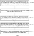
- FIG. 1 is a flowchart showing a method for determining a charging time length of a battery according to an exemplary embodiment. As shown in FIG. 1 , the method for determining a charging time length of a battery includes following steps:
- a current charging state type of the battery is acquired after it is monitored that the battery of the electronic device enters a charging state, a charging stage of the battery of the electronic device is determined, and the charging time length required by the battery is determined according to the charging state type and the charging stage.
- the method for determining the charging time length of the battery provided by the present disclosure can determine the charging time length required by the battery in real time according to the type of charging state and the charging stage of the battery. By distinguishing different charging scenarios, a more accurate charging time can be estimated, and the user experience is improved.
- the charging state type of the battery may include an off-screen charging state or a bright-screen charging state.
- the off-screen charging state is that the electronic device is in a non-power consumption state, and the screen of the electronic device is in the off-screen state.
- the bright-screen charging state means that the electronic device is in a power consumption state, and the electronic device is in use, for example, the smart terminal is in a call, a game, or a movie viewing state, and so on.
- the method for determining the charging time length of the battery takes into account the charging state type of the battery, and determines the time length of the charging according to the scenarios of different types of charging states, thereby improving the accuracy of determining the charging time length required by the battery of the electronic device.
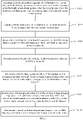
- FIG. 2 shows a flowchart of a method for determining the charging time length required by the battery according to the charging state type and the charging stage of step S13 in FIG. 1 :
- the battery charging stage may include a constant current (CC) charging stage and a constant voltage (CV) charging stage.
- a constant current charging manner can be used.
- the voltage of the battery is very low at the beginning of charging. If the battery is not charged with a constant current, the charging current is very large, which will affect the battery life of the electronic device.
- a constant voltage charging manner can be used.
- the constant voltage is a terminal voltage when the battery of the electronic device is fully charged, to prevent the battery of the electronic device from being overcharged.
- the first charging time length of the constant current charging stage is determined first, and then the second charging time length of the constant voltage charging stage is determined.
- the sum of the first charging time length and the second charging time length is determined as the charging time length required by the battery.
- the first existing electric quantity Q 1 of the battery in the current stage represents the remaining electric quantity of the battery of the electronic device in the current stage.
- the first maximum electric quantity Q 2 represents, in the off-screen charging state, the electric quantity of the battery at the moment when the battery is charged from the constant current charging stage to the constant voltage charging stage under the off-screen charging state.
- FIG. 3 shows a flowchart of a method for acquiring a first maximum electric quantity Q 2 in the constant current charging stage under the off-screen charging state of step S132 in FIG. 2 :
- the charging voltage is the terminal voltage V max when the battery of the electronic device is fully charged. Then, the voltage at the moment from the constant current charging stage to the constant voltage charging stage during the battery charging process is V max .
- the first maximum electric quantity Q 2 in the constant current charging stage can be determined according to the open circuit voltage V ocv2 at the moment from the constant current charging stage to the constant voltage charging stage during the battery charging process.
- the first maximum electric quantity Q 2 in the constant current charging stage under the off-screen state can be determined according to the OCV model.
- FIG. 4 illustrates a schematic diagram of the OCV curve of the OCV model.
- the abscissa is the capacity Q of the battery, and the ordinate is the open circuit voltage V ocv of the battery.
- V ocv2 is determined according to the terminal voltage V max when the battery of the electronic device is fully charged
- the first maximum electric quantity Q 2 in the constant current charging stage under the off-screen state is determined according to the OCV curve shown in FIG. 4 .
- the second charging time length T 2 of the constant voltage stage under the off-screen charging state is determined.
- the second charging time length of the constant voltage charging stage under the off-screen charging state may be determined based on the first maximum electric quantity Q 2 in the constant current charging stage under the off-screen state and the maximum electric quantity Q max of the battery.
- the open circuit voltage can be determined according to the fitting formula of the open circuit voltage.
- Q is the electric quantity of the battery
- a n is a parameter for describing the material properties of the battery
- the open circuit voltage V ocv is fitted with a high-order polynomial of the battery capacity Q. Its degree of fitting is larger than or equal to 0.98.
- the to-be-loaded impedance R of the battery is determined according to the fitting formula of the to-be-loaded impedance of the battery.
- Q is the capacity of the battery
- B n is a parameter for describing the material properties of the battery
- the to-be-loaded impedance is fitted with a high-order polynomial of the battery capacity Q. Its degree of fitting is larger than or equal to 0.98.
- T is the charging time length of the battery
- a n and B n are parameters for describing the material properties of the battery
- Q 3 is the existing electric quantity acquired at the current stage
- Q max is the maximum electric quantity of the battery
- V max is the terminal voltage when the battery is fully charged.
- the second charging time length T 2 of the constant voltage charging stage in the off-screen charging state is determined, and the sum of the first charging time length T 1 and the second charging time length T 2 is determined as the charging time length required by the battery of the electronic device.
- the method for determining the battery charging time length when the type of the charging state is the off-screen charging state and the charging stage is in the constant current charging stage, the first charging time length in the constant current charging stage and the second charging time length in the constant voltage charging stage under the off-screen charging state may be calculated, and the sum of the charging time lengths of the two stages is determined as the charging time length of battery charging.
- the method for determining the battery charging time length provided by the present disclosure fully considers the characteristics of each stage of the constant current charging stage and the constant voltage charging stage during charging the battery under the off-screen charging state, and determines the charging time length of each stage separately, and finally determines the charging time length of the battery, which improves the accuracy of the method for determining the charging time length of the battery.
- FIG. 5 shows a flowchart of a method for determining the charging time length required by the battery according to the charging state type and the charging stage of step S13 in FIG. 1 :
- a second existing electric quantity Q 3 in the current stage when the electronic device is in the constant voltage stage under the off-screen charging state may be acquired, and the charging time length of the constant voltage charging stage under the off-screen charging state may be determined according to the second existing electric quantity Q 3 in the current stage and the maximum electric quantity Q max of the battery.
- the charging time length of the constant voltage charging stage under the off-screen charging state is the charging time length required by the battery.
- the open circuit voltage can be determined according to the fitting formula of the open circuit voltage.
- Q is the electric quantity of the battery
- a n is a parameter for describing the material properties of the battery
- the open circuit voltage V ocv is fitted with a high-order polynomial of the battery capacity Q. Its degree of fitting is larger than or equal to 0.98.
- the to-be-loaded impedance R of the battery is determined according to the fitting formula of the to-be-loaded impedance of the battery.
- Q is the capacity of the battery
- B n is a parameter for describing the material properties of the battery
- the to-be-loaded impedance is fitted with a high-order polynomial of the battery capacity Q. Its degree of fitting is larger than or equal to 0.98.
- T is the charging time length of the battery
- a n and B n are parameters for describing the material properties of the battery
- Q 3 is the existing electric quantity acquired at the current stage
- Q max is the maximum electric quantity of the battery
- V max is the terminal voltage when the battery is fully charged.
- the method for determining the battery charging time length provided by the present disclosure, when the type of the charging state is the off-screen charging state and the charging stage is in the constant voltage charging stage, it can only consider the characteristics of the constant voltage charging stage, and only the charging time length of the constant voltage charging stage is determined as the charging time length of the battery, and the accuracy of the method for determining the charging time length of the battery is improved.
- FIG. 6 shows a flowchart of a method for determining the charging time length required by the battery according to the charging state type and the charging stage of step S13 in FIG. 1 :
- the fourth charging time length of the constant current charging stage is determined first, and then the fifth charging time length of the constant voltage charging stage is determined.
- the sum of the fourth charging time length and the fifth charging time length is determined as the charging time length required by charging of the battery.
- the third existing electric quantity Q 4 in the current stage of the battery represents the remaining electric quantity in the current stage of the battery of the electronic device.
- the third maximum electric quantity Q 5 of the constant current charging stage in the bright-screen charging state represents the electric quantity of the battery at the moment from the constant current charging stage to the constant voltage charging stage during the battery charging process under the bright-screen charging state.
- FIG. 7 shows a flowchart of the method for acquiring a third maximum electric quantity Q 5 in the constant current charging stage under the bright-screen charging state of step S139 in FIG. 6 :
- the charging voltage is the terminal voltage V max when the battery of the electronic device is fully charged. Then, the voltage at the moment from the constant current charging stage to the constant voltage charging stage during the battery charging is V max .
- the third maximum electric quantity Q 5 in the constant current charging stage under the bright-screen state can be determined according to the open circuit voltage V ocv5 at the moment from the constant current charging stage to the constant voltage charging stage during the battery charging process.
- the third maximum electric quantity Q 5 in the constant current charging stage can be determined according to the OCV model.
- FIG. 8 shows a flowchart of the method for determining a time length t f for reaching a highest temperature under the third charging current I 2 of the constant current charging stage under the bright-screen charging state:
- the time length t f for reaching the highest temperature under the charging current of the constant current charging stage in the bright-screen charging state is determined according to the temperature rise speed of the constant current charging stage under the bright-screen charging state.
- the temperature rise speed F' of the constant current charging stage under the bright-screen charging state may be determined in any determinable manner, for example, it may be determined in the following manner. As shown in FIG. 9, FIG. 9 shows a flowchart of the method for determining a temperature rise speed F' of the constant current charging stage under the bright-screen charging state of step S1411 in FIG. 8 :
- the temperature difference between the two endpoint temperatures in a unit time is the temperature rise speed in the unit time.
- the temperature values of the two endpoints in 1 second are read and the difference between the two temperature values is calculated to obtain the temperature rise speed in 1 second.
- the temperature difference within N units of time can be obtained, and the average value of the temperature difference within the N units of time is determined as the temperature rise speed F' in the constant current charging stage under the bright-screen charging state.
- the N units of time may be continuous or discontinuous N units of time.
- N units of time may be obtained according to equal interval time length, which is not limited herein.
- the time length t f for reaching the highest temperature under the third charging current can be determined according to the determined temperature rise speed F'.
- the time length t f for reaching the highest temperature can be determined as follows.
- a fourth charging time length of the constant current charging stage under the bright-screen charging state is determined according to the time length t f for reaching the highest temperature and the third charging time length.
- FIG. 10 shows a flowchart of a method for determining a fourth charging time length of the constant current charging stage under the bright-screen charging state according to the time length for reaching the highest temperature and the third charging time length of step S142 in FIG. 6 :
- the time length t f for the battery reaching the highest temperature is less than the third charging time length T 3 , it means that in the constant current charging stage under the bright-screen charging state, under the third charging current, after the charging time length t f , the battery of the electronic device reaches the highest temperature of the battery.
- the charging time length of the electronic device of the constant current charging stage under the bright-screen charging state will be a sum of the time length t f for reaching the highest temperature and the sixth charging time length T 6 , and determined as the fourth charging time length T 4 .
- the charging time length of the electronic device of the constant current charging stage under the bright-screen charging state is the third charging time length T 3 , that is, the fourth charging time length T 4 is the third charging time length T 3 .
- the fifth charging time length T 5 of the constant voltage stage is determined.
- the fifth charging time length of the constant voltage charging stage in the bright-screen charging state can be determined according to the maximum electric quantity of the constant current charging stage in the bright-screen charging state and the maximum electric quantity Q max of the battery.
- the maximum electric quantity in the constant current charging stage in the bright-screen charging state is Q 5 .
- the maximum electric quantity in the constant current charging stage under the bright-screen charging state is the maximum electric quantity Q 7 after the current adjustment of the electronic device in the constant current charging stage under the bright-screen charging state.
- the open circuit voltage can be determined according to the fitting formula of the open circuit voltage.
- Q is the electric quantity of the battery
- a n is a parameter for describing the material properties of the battery
- the open circuit voltage V ocv is fitted with a high-order polynomial of the battery capacity Q. Its degree of fitting is larger than or equal to 0.98.
- the to-be-loaded impedance R of the battery is determined according to the fitting formula of the to-be-loaded impedance of the battery.
- Q is the capacity of the battery
- B n is a parameter for describing the material properties of the battery
- the to-be-loaded impedance is fitted with a high-order polynomial of the battery capacity Q. Its degree of fitting is larger than or equal to 0.98.
- T 5 is the fifth charging time length in the constant voltage stage under the bright-screen charging state
- a n and B n are parameters for describing the material properties of the battery
- Q 5 is the maximum electric quantity of the electronic device in the constant current charging stage under the bright-screen charging state
- Q max is the maximum electric quantity of the battery
- V max is the terminal voltage when the battery is fully charged
- T 5 is the fifth charging time length of the constant voltage stage in the bright-screen charging state
- a n and B n are parameters for describing the material properties of the battery
- Q 7 is the maximum electric quantity of the electronic device in the constant current charging stage under the bright-screen charging state
- Q max is the maximum electric quantity of the battery
- the fifth charging time length T 5 of the electronic device in the constant voltage stage under the bright-screen charging state is determined, and the sum of the fourth charging time length T 4 of the electronic device in the constant current charging stage under the bright-screen charging state and the fifth charging time length T 5 of the electronic device in the constant voltage stage under the bright-screen charging state is determined as the charging time length of the battery.
- the method for determining the charging time length of the battery provided by the present disclosure, when the charging state type is the bright-screen charging state and the charging stage is in the constant current charging stage, under the bright-screen charging state, the influence of the power consumption of the electronic device on the temperature of the electronic device and the influence of the temperature of the electronic device on the charging time length of the battery of the electronic device are considered. According to the influence of temperature, a method for determining the charging time length of the battery is provided, which improves the accuracy of the method for determining the charging time length of the battery.
- FIG. 11 shows a flowchart of a method for determining the charging time length required by the battery according to the charging state type and the charging stage of step S13 in FIG. 1 :
- the charging time length of the constant voltage charging stage is the charging time length of the battery.
- the open circuit voltage can be determined according to the fitting formula of the open circuit voltage.
- Q is the electric quantity of the battery
- a n is a parameter for describing the material properties of the battery
- the open circuit voltage V ocv is fitted with a high-order polynomial of the battery capacity Q. Its degree of fitting is larger than or equal to 0.98.
- the to-be-loaded impedance R of the battery is determined according to the fitting formula of the to-be-loaded impedance of the battery.
- Q is the capacity of the battery
- B n is a parameter for describing the material properties of the battery
- the to-be-loaded impedance is fitted with a high-order polynomial of the battery capacity Q. Its degree of fitting is larger than or equal to 0.98.
- T is the charging time length
- a n and B n are parameters for describing the material properties of the battery
- Q 8 is the obtained fourth existing electric quantity in the current stage
- Q max is the the maximum electric quantity of the battery
- V max is the terminal voltage when the battery is fully charged.
- the method for determining the battery charging time length provided by the present disclosure, when the type of the charging state is the bright-screen charging state and the charging stage is in the constant voltage charging stage, it can only consider the characteristics of the constant voltage charging stage, and only the charging time length of the constant voltage charging stage is determined as the charging time length of the battery, and the accuracy of the method for determining the charging time length of the battery is improved.
- FIG. 12 is a block diagram showing an apparatus for determining the charging time length of the battery according to an exemplary embodiment.
- the determining apparatus includes an acquiring module 1201, a first determining module 1202, and a second determining module 1203.
- the acquiring module 1201 is configured to acquire a current charging state type of the battery after it is monitored that the battery of the electronic device enters a charging state.
- the first determining module 1202 is configured to determine a charging stage of the battery, wherein the charging stage includes a constant current charging stage and a constant voltage charging stage.
- the second determining module 1203 is configured to determine the charging time length required by the battery according to the charging state type and the charging stage.
- the method for determining the charging time length of the battery provided by the present disclosure can determine the charging time length required by the battery in real time according to the charging state type and the charging stage of the battery. By distinguishing different charging scenarios, a more accurate charging time can be estimated, and the user experience is improved.
- FIG. 13 is a block diagram showing an apparatus 1300 for determining the charging time length of the battery according to an exemplary embodiment.
- the apparatus 1300 can be a mobile phone, a computer, a digital broadcast terminal, a messaging apparatus, a game console, a tablet apparatus, a medical apparatus, a fitness apparatus, a personal digital assistant, and the like.
- the apparatus 1300 may include one or more of the following components: a processing component 1302, a memory 1304, a power component 1306, a multimedia component 1308, an audio component 1310, an input/output (I/O) interface 1312, a sensor component 1314, and a communication component 1316.
- a processing component 1302 a memory 1304, a power component 1306, a multimedia component 1308, an audio component 1310, an input/output (I/O) interface 1312, a sensor component 1314, and a communication component 1316.
- the processing component 1302 typically controls overall operations of the apparatus 1300, such as the operations associated with display, phone call, data communications, camera operations, and recording operations.
- the processing component 1302 may include one or more processors 1320 to execute instructions, to perform all or part of the steps of the above method.
- the processing component 1302 may include one or more modules which facilitate the interaction between the processing component 1302 and other components.
- the processing component 1302 may include a multimedia module to facilitate the interaction between the multimedia component 1308 and the processing component 1302.
- the memory 1304 is configured to store various types of data to support the operation of the apparatus 1300. Examples of such data include instructions for any applications or methods operated on the apparatus 1300, contact data, telephone directory data, messages, pictures, video, etc.
- the memory 1304 may be implemented using any type of volatile or non-volatile memory devices, or a combination thereof, such as a static random access memory (SRAM), an electrically erasable programmable read-only memory (EEPROM), an erasable programmable read-only memory (EPROM), a programmable read-only memory (PROM), a read-only memory (ROM), a magnetic memory, a flash memory, a magnetic or optical disk.
- SRAM static random access memory
- EEPROM electrically erasable programmable read-only memory
- EPROM erasable programmable read-only memory
- PROM programmable read-only memory
- ROM read-only memory
- magnetic memory a magnetic memory
- flash memory a flash memory
- magnetic or optical disk a magnetic
- the power component 1306 provides power to various components of the apparatus 1300.
- the power component 1306 may include a power management system, one or more power sources, and any other components associated with the generation, management, and distribution of power in the apparatus 1300.
- the multimedia component 1308 includes a screen providing an output interface between the apparatus 1300 and the user.
- the screen may include a liquid crystal display (LCD) and a touch panel (TP). If the screen includes the touch panel, the screen may be implemented as a touch screen to receive input signals from the user.
- the touch panel includes one or more touch sensors to sense touches, swipes, and gestures on the touch panel. The touch sensors may not only sense a boundary of a touch or swipe action, but also sense a period of time and a pressure associated with the touch or swipe action.
- the multimedia component 1308 includes a front camera and/or a rear camera. When the apparatus 1300 is in an operation mode, such as a shooting mode or a video mode, the front camera and/or the rear camera can receive external multimedia data. Each front and rear camera can be a fixed optical lens system or have focal length and optical zoom capability.
- the audio component 1310 is configured to output and/or input audio signals.
- the audio component 1310 includes a microphone ("MIC") configured to receive an external audio signal when the apparatus 1300 is in an operation mode, such as a call mode, a recording mode, and a voice recognition mode.
- the received audio signal may be further stored in the memory 1304 or transmitted via the communication component 1316.
- the audio component 1310 further includes a speaker to output audio signals.
- the I/O interface 1312 provides an interface between the processing component 1302 and peripheral interface modules, such as a keyboard, a click wheel, buttons, and the like. These buttons may include, but are not limited to, a home button, a volume button, a start button, and a lock button.
- the sensor component 1314 includes one or more sensors to provide status assessments of various aspects of the apparatus 1300. For instance, the sensor component 1314 may detect an on/off status of the apparatus 1300, relative positioning of components, e.g., the display and the keypad, of the apparatus 1300, a change in position of the apparatus 1300 or a component of the apparatus 1300, a presence or absence of user contact with the apparatus 1300, an orientation or an acceleration/deceleration of the apparatus 1300, and a change in temperature of the apparatus 1300.
- the sensor component 1314 may include a proximity sensor configured to detect the presence of nearby objects without any physical contact.
- the sensor component 1314 may also include a light sensor, such as a CMOS or CCD image sensor, for use in imaging applications.
- the sensor component 1314 may also include an accelerometer sensor, a gyroscope sensor, a magnetic sensor, a pressure sensor, or a temperature sensor.
- the communication component 1316 is configured to facilitate communication, wired or wirelessly, between the apparatus 1300 and other devices.
- the apparatus 1300 can access a wireless network based on a communication standard, such as WiFi, 2G, or 3G, 4G/LTE, 5G/NR or a combination thereof.
- the communication component 1316 receives a broadcast signal or broadcast associated information from an external broadcast management system via a broadcast channel.
- the communication component 1316 further includes a near field communication (NFC) module to facilitate short-range communications.
- the NFC module may be implemented based on a radio frequency identification (RFID) technology, an infrared data association (IrDA) technology, an ultra-wideband (UWB) technology, a Bluetooth (BT) technology, and other technologies.
- RFID radio frequency identification
- IrDA infrared data association
- UWB ultra-wideband
- BT Bluetooth
- the apparatus 1300 may be implemented with one or more application specific integrated circuits (ASICs), digital signal processors (DSPs), digital signal processing devices (DSPDs), programmable logic devices (PLDs), field programmable gate arrays (FPGAs), remote control devices, micro remote control devices, microprocessors, or other electronic components, to perform the above method.
- ASICs application specific integrated circuits
- DSPs digital signal processors
- DSPDs digital signal processing devices
- PLDs programmable logic devices
- FPGAs field programmable gate arrays
- remote control devices micro remote control devices, microprocessors, or other electronic components, to perform the above method.
- non-transitory computer-readable storage medium including instructions, such as included in the memory 1304, executable by the processor 1320 in the apparatus 1300 to perform the above method.
- the non-transitory computer-readable storage medium may be a ROM, a random access memory (RAM), a CD-ROM, a magnetic tape, a floppy disc, an optical data storage apparatus, and the like.
- a non-transitory computer-readable storage medium wherein when instructions in the storage medium are executed by a processor of an electronic device, the electronic device is able to execute a method for determining a charging time length of a battery, the method including:
Landscapes
- Engineering & Computer Science (AREA)
- Power Engineering (AREA)
- Physics & Mathematics (AREA)
- General Physics & Mathematics (AREA)
- Charge And Discharge Circuits For Batteries Or The Like (AREA)
Applications Claiming Priority (1)
| Application Number | Priority Date | Filing Date | Title |
|---|---|---|---|
| CN202110218636.3A CN114977348B (zh) | 2021-02-26 | 2021-02-26 | 电池充电时长的确定方法、装置及存储介质 |
Publications (1)
| Publication Number | Publication Date |
|---|---|
| EP4050751A1 true EP4050751A1 (de) | 2022-08-31 |
Family
ID=77710480
Family Applications (1)
| Application Number | Title | Priority Date | Filing Date |
|---|---|---|---|
| EP21195684.2A Pending EP4050751A1 (de) | 2021-02-26 | 2021-09-09 | Verfahren und vorrichtung zur bestimmung der ladezeitdauer einer batterie |
Country Status (3)
| Country | Link |
|---|---|
| US (1) | US11635468B2 (de) |
| EP (1) | EP4050751A1 (de) |
| CN (1) | CN114977348B (de) |
Cited By (1)
| Publication number | Priority date | Publication date | Assignee | Title |
|---|---|---|---|---|
| CN119010256A (zh) * | 2024-07-12 | 2024-11-22 | 荣耀终端有限公司 | 充电方法、电子设备、计算机程序产品及可读存储介质 |
Citations (2)
| Publication number | Priority date | Publication date | Assignee | Title |
|---|---|---|---|---|
| CN105322591B (zh) * | 2014-08-01 | 2018-05-04 | 联想移动通信科技有限公司 | 一种显示电子设备充电时间的方法、装置及电子设备 |
| CN106877435B (zh) * | 2017-03-14 | 2020-07-07 | 上海摩软通讯技术有限公司 | 一种终端的充电方法及终端 |
Family Cites Families (6)
| Publication number | Priority date | Publication date | Assignee | Title |
|---|---|---|---|---|
| JPH10172616A (ja) * | 1996-12-17 | 1998-06-26 | Sanyo Electric Co Ltd | 充電装置 |
| TWI523298B (zh) * | 2015-01-16 | 2016-02-21 | 新普科技股份有限公司 | 預估鋰離子電池剩餘充電時間之方法以及充電監測器 |
| US10983168B2 (en) * | 2016-11-18 | 2021-04-20 | Semiconductor Components Industries, Llc | Methods and apparatus for reporting a relative state of charge of a battery |
| US20180145514A1 (en) * | 2016-11-21 | 2018-05-24 | Microsoft Technology Licensing, Llc | Predictive battery charge and discharge analysis |
| CN108092360A (zh) * | 2017-12-25 | 2018-05-29 | 深圳市汉普电子技术开发有限公司 | 控制移动终端充电电流方法、装置及计算机可读存储介质 |
| CN110909443A (zh) * | 2019-10-12 | 2020-03-24 | 北京航空航天大学 | 一种高精度电池组充电剩余时间估算方法及系统 |
-
2021
- 2021-02-26 CN CN202110218636.3A patent/CN114977348B/zh active Active
- 2021-09-02 US US17/465,226 patent/US11635468B2/en active Active
- 2021-09-09 EP EP21195684.2A patent/EP4050751A1/de active Pending
Patent Citations (2)
| Publication number | Priority date | Publication date | Assignee | Title |
|---|---|---|---|---|
| CN105322591B (zh) * | 2014-08-01 | 2018-05-04 | 联想移动通信科技有限公司 | 一种显示电子设备充电时间的方法、装置及电子设备 |
| CN106877435B (zh) * | 2017-03-14 | 2020-07-07 | 上海摩软通讯技术有限公司 | 一种终端的充电方法及终端 |
Non-Patent Citations (1)
| Title |
|---|
| SIVARANJANI J ET AL: "Intelligent charging system for dedicated applications using lithium ion battery", 2016 ONLINE INTERNATIONAL CONFERENCE ON GREEN ENGINEERING AND TECHNOLOGIES (IC-GET), IEEE, 19 November 2016 (2016-11-19), pages 1 - 7, XP033092884, [retrieved on 20170501], DOI: 10.1109/GET.2016.7916816 * |
Cited By (1)
| Publication number | Priority date | Publication date | Assignee | Title |
|---|---|---|---|---|
| CN119010256A (zh) * | 2024-07-12 | 2024-11-22 | 荣耀终端有限公司 | 充电方法、电子设备、计算机程序产品及可读存储介质 |
Also Published As
| Publication number | Publication date |
|---|---|
| CN114977348B (zh) | 2025-04-22 |
| US20220276313A1 (en) | 2022-09-01 |
| US11635468B2 (en) | 2023-04-25 |
| CN114977348A (zh) | 2022-08-30 |
Similar Documents
| Publication | Publication Date | Title |
|---|---|---|
| US10116157B2 (en) | Method and device for charging batteries in mobile devices | |
| CN107843802B (zh) | 内短路检测方法及装置 | |
| EP3832840B1 (de) | Verfahren und vorrichtung zum laden, endgerätevorrichtung und speichermedium | |
| US12212175B2 (en) | Charging control method and apparatus, electronic device and storage medium | |
| US12160129B2 (en) | Charging control method, charging control device and storage medium | |
| CN106786871A (zh) | 充电控制方法、装置及系统 | |
| EP4068560A1 (de) | Verfahren und vorrichtung zur vorhersage der verbleibenden ladezeit und speichermedium | |
| CN112448053B (zh) | 移动终端的充电方法、装置、终端及存储介质 | |
| CN107331910B (zh) | 充电方法及装置 | |
| CN111601377A (zh) | 温度的控制方法、装置及存储介质 | |
| CN112421702A (zh) | 锂电池充电方法及装置 | |
| US11686776B2 (en) | Prediction method and apparatus of battery health, and storage medium | |
| CN112448052B (zh) | 电池充电控制方法及装置 | |
| CN108539804B (zh) | 电池充电控制方法、电池充电控制装置和电子设备 | |
| EP3828716A1 (de) | Verfahren und vorrichtung zur identifizierung einer elektronischen vorrichtung, endgerät und elektronische vorrichtung | |
| EP4050751A1 (de) | Verfahren und vorrichtung zur bestimmung der ladezeitdauer einer batterie | |
| CN109038697A (zh) | 充电控制方法及充电控制装置、电子设备 | |
| CN114069744A (zh) | 一种智能充电方法、装置及存储介质 | |
| CN113675902A (zh) | 电池充电方法、电池充电装置及存储介质 | |
| US10187498B2 (en) | Method and apparatus for setting waiting time duration | |
| CN114156957B (zh) | 电池充电方法、装置及存储介质 | |
| CN118263938A (zh) | 充电方法、装置、电子设备及储存介质 | |
| US12609551B2 (en) | Method of charging processing, electronic device and storage medium | |
| CN115224750B (zh) | 充电时长确定方法、装置、终端及存储介质 | |
| CN117375131A (zh) | 电池温度控制方法、装置、终端及存储介质 |
Legal Events
| Date | Code | Title | Description |
|---|---|---|---|
| PUAI | Public reference made under article 153(3) epc to a published international application that has entered the european phase |
Free format text: ORIGINAL CODE: 0009012 |
|
| STAA | Information on the status of an ep patent application or granted ep patent |
Free format text: STATUS: THE APPLICATION HAS BEEN PUBLISHED |
|
| AK | Designated contracting states |
Kind code of ref document: A1 Designated state(s): AL AT BE BG CH CY CZ DE DK EE ES FI FR GB GR HR HU IE IS IT LI LT LU LV MC MK MT NL NO PL PT RO RS SE SI SK SM TR |
|
| STAA | Information on the status of an ep patent application or granted ep patent |
Free format text: STATUS: REQUEST FOR EXAMINATION WAS MADE |
|
| 17P | Request for examination filed |
Effective date: 20230223 |
|
| RBV | Designated contracting states (corrected) |
Designated state(s): AL AT BE BG CH CY CZ DE DK EE ES FI FR GB GR HR HU IE IS IT LI LT LU LV MC MK MT NL NO PL PT RO RS SE SI SK SM TR |
|
| STAA | Information on the status of an ep patent application or granted ep patent |
Free format text: STATUS: EXAMINATION IS IN PROGRESS |
|
| 17Q | First examination report despatched |
Effective date: 20251015 |