EP4050697A1 - Equalization method and device for battery module, battery module, and power supply management controller - Google Patents
Equalization method and device for battery module, battery module, and power supply management controller Download PDFInfo
- Publication number
- EP4050697A1 EP4050697A1 EP20923689.2A EP20923689A EP4050697A1 EP 4050697 A1 EP4050697 A1 EP 4050697A1 EP 20923689 A EP20923689 A EP 20923689A EP 4050697 A1 EP4050697 A1 EP 4050697A1
- Authority
- EP
- European Patent Office
- Prior art keywords
- battery core
- battery
- management controller
- power management
- fully
- Prior art date
- Legal status (The legal status is an assumption and is not a legal conclusion. Google has not performed a legal analysis and makes no representation as to the accuracy of the status listed.)
- Granted
Links
Images


Classifications
-
- B—PERFORMING OPERATIONS; TRANSPORTING
- B60—VEHICLES IN GENERAL
- B60L—PROPULSION OF ELECTRICALLY-PROPELLED VEHICLES; SUPPLYING ELECTRIC POWER FOR AUXILIARY EQUIPMENT OF ELECTRICALLY-PROPELLED VEHICLES; ELECTRODYNAMIC BRAKE SYSTEMS FOR VEHICLES IN GENERAL; MAGNETIC SUSPENSION OR LEVITATION FOR VEHICLES; MONITORING OPERATING VARIABLES OF ELECTRICALLY-PROPELLED VEHICLES; ELECTRIC SAFETY DEVICES FOR ELECTRICALLY-PROPELLED VEHICLES
- B60L58/00—Methods or circuit arrangements for monitoring or controlling batteries or fuel cells, specially adapted for electric vehicles
- B60L58/10—Methods or circuit arrangements for monitoring or controlling batteries or fuel cells, specially adapted for electric vehicles for monitoring or controlling batteries
- B60L58/12—Methods or circuit arrangements for monitoring or controlling batteries or fuel cells, specially adapted for electric vehicles for monitoring or controlling batteries responding to state of charge [SoC]
- B60L58/13—Maintaining the SoC within a determined range
-
- H—ELECTRICITY
- H02—GENERATION; CONVERSION OR DISTRIBUTION OF ELECTRIC POWER
- H02J—ELECTRIC POWER NETWORKS; CIRCUIT ARRANGEMENTS OR SYSTEMS FOR SUPPLYING OR DISTRIBUTING ELECTRIC POWER; SYSTEMS FOR STORING ELECTRIC ENERGY
- H02J7/00—Circuit arrangements for charging or discharging batteries or for supplying loads from batteries
- H02J7/50—Circuit arrangements for charging or discharging batteries or for supplying loads from batteries acting upon multiple batteries simultaneously or sequentially
- H02J7/52—Circuit arrangements for charging or discharging batteries or for supplying loads from batteries acting upon multiple batteries simultaneously or sequentially for charge balancing, e.g. equalisation of charge between batteries
- H02J7/54—Passive balancing, e.g. using resistors or parallel MOSFETs
-
- B—PERFORMING OPERATIONS; TRANSPORTING
- B60—VEHICLES IN GENERAL
- B60L—PROPULSION OF ELECTRICALLY-PROPELLED VEHICLES; SUPPLYING ELECTRIC POWER FOR AUXILIARY EQUIPMENT OF ELECTRICALLY-PROPELLED VEHICLES; ELECTRODYNAMIC BRAKE SYSTEMS FOR VEHICLES IN GENERAL; MAGNETIC SUSPENSION OR LEVITATION FOR VEHICLES; MONITORING OPERATING VARIABLES OF ELECTRICALLY-PROPELLED VEHICLES; ELECTRIC SAFETY DEVICES FOR ELECTRICALLY-PROPELLED VEHICLES
- B60L58/00—Methods or circuit arrangements for monitoring or controlling batteries or fuel cells, specially adapted for electric vehicles
- B60L58/10—Methods or circuit arrangements for monitoring or controlling batteries or fuel cells, specially adapted for electric vehicles for monitoring or controlling batteries
- B60L58/18—Methods or circuit arrangements for monitoring or controlling batteries or fuel cells, specially adapted for electric vehicles for monitoring or controlling batteries of two or more battery modules
- B60L58/21—Methods or circuit arrangements for monitoring or controlling batteries or fuel cells, specially adapted for electric vehicles for monitoring or controlling batteries of two or more battery modules having the same nominal voltage
-
- B—PERFORMING OPERATIONS; TRANSPORTING
- B60—VEHICLES IN GENERAL
- B60L—PROPULSION OF ELECTRICALLY-PROPELLED VEHICLES; SUPPLYING ELECTRIC POWER FOR AUXILIARY EQUIPMENT OF ELECTRICALLY-PROPELLED VEHICLES; ELECTRODYNAMIC BRAKE SYSTEMS FOR VEHICLES IN GENERAL; MAGNETIC SUSPENSION OR LEVITATION FOR VEHICLES; MONITORING OPERATING VARIABLES OF ELECTRICALLY-PROPELLED VEHICLES; ELECTRIC SAFETY DEVICES FOR ELECTRICALLY-PROPELLED VEHICLES
- B60L58/00—Methods or circuit arrangements for monitoring or controlling batteries or fuel cells, specially adapted for electric vehicles
- B60L58/10—Methods or circuit arrangements for monitoring or controlling batteries or fuel cells, specially adapted for electric vehicles for monitoring or controlling batteries
- B60L58/18—Methods or circuit arrangements for monitoring or controlling batteries or fuel cells, specially adapted for electric vehicles for monitoring or controlling batteries of two or more battery modules
- B60L58/22—Balancing the charge of battery modules
-
- H—ELECTRICITY
- H01—ELECTRIC ELEMENTS
- H01M—PROCESSES OR MEANS, e.g. BATTERIES, FOR THE DIRECT CONVERSION OF CHEMICAL ENERGY INTO ELECTRICAL ENERGY
- H01M10/00—Secondary cells; Manufacture thereof
- H01M10/42—Methods or arrangements for servicing or maintenance of secondary cells or secondary half-cells
- H01M10/425—Structural combination with electronic components, e.g. electronic circuits integrated to the outside of the casing
-
- H—ELECTRICITY
- H01—ELECTRIC ELEMENTS
- H01M—PROCESSES OR MEANS, e.g. BATTERIES, FOR THE DIRECT CONVERSION OF CHEMICAL ENERGY INTO ELECTRICAL ENERGY
- H01M10/00—Secondary cells; Manufacture thereof
- H01M10/42—Methods or arrangements for servicing or maintenance of secondary cells or secondary half-cells
- H01M10/44—Methods for charging or discharging
-
- H—ELECTRICITY
- H01—ELECTRIC ELEMENTS
- H01M—PROCESSES OR MEANS, e.g. BATTERIES, FOR THE DIRECT CONVERSION OF CHEMICAL ENERGY INTO ELECTRICAL ENERGY
- H01M50/00—Constructional details or processes of manufacture of the non-active parts of electrochemical cells other than fuel cells, e.g. hybrid cells
- H01M50/50—Current conducting connections for cells or batteries
- H01M50/502—Interconnectors for connecting terminals of adjacent batteries; Interconnectors for connecting cells outside a battery casing
- H01M50/509—Interconnectors for connecting terminals of adjacent batteries; Interconnectors for connecting cells outside a battery casing characterised by the type of connection, e.g. mixed connections
- H01M50/51—Connection only in series
-
- H—ELECTRICITY
- H02—GENERATION; CONVERSION OR DISTRIBUTION OF ELECTRIC POWER
- H02J—ELECTRIC POWER NETWORKS; CIRCUIT ARRANGEMENTS OR SYSTEMS FOR SUPPLYING OR DISTRIBUTING ELECTRIC POWER; SYSTEMS FOR STORING ELECTRIC ENERGY
- H02J7/00—Circuit arrangements for charging or discharging batteries or for supplying loads from batteries
- H02J7/34—Parallel operation in networks using both storage and other DC sources, e.g. providing buffering
- H02J7/342—The other DC source being a battery actively interacting with the first one, i.e. battery to battery charging
-
- H—ELECTRICITY
- H02—GENERATION; CONVERSION OR DISTRIBUTION OF ELECTRIC POWER
- H02J—ELECTRIC POWER NETWORKS; CIRCUIT ARRANGEMENTS OR SYSTEMS FOR SUPPLYING OR DISTRIBUTING ELECTRIC POWER; SYSTEMS FOR STORING ELECTRIC ENERGY
- H02J7/00—Circuit arrangements for charging or discharging batteries or for supplying loads from batteries
- H02J7/50—Circuit arrangements for charging or discharging batteries or for supplying loads from batteries acting upon multiple batteries simultaneously or sequentially
- H02J7/52—Circuit arrangements for charging or discharging batteries or for supplying loads from batteries acting upon multiple batteries simultaneously or sequentially for charge balancing, e.g. equalisation of charge between batteries
-
- H—ELECTRICITY
- H02—GENERATION; CONVERSION OR DISTRIBUTION OF ELECTRIC POWER
- H02J—ELECTRIC POWER NETWORKS; CIRCUIT ARRANGEMENTS OR SYSTEMS FOR SUPPLYING OR DISTRIBUTING ELECTRIC POWER; SYSTEMS FOR STORING ELECTRIC ENERGY
- H02J7/00—Circuit arrangements for charging or discharging batteries or for supplying loads from batteries
- H02J7/80—Circuit arrangements for charging or discharging batteries or for supplying loads from batteries including monitoring or indicating arrangements
- H02J7/82—Control of state of charge [SOC]
- H02J7/825—Detection of fully charged condition
-
- H—ELECTRICITY
- H02—GENERATION; CONVERSION OR DISTRIBUTION OF ELECTRIC POWER
- H02J—ELECTRIC POWER NETWORKS; CIRCUIT ARRANGEMENTS OR SYSTEMS FOR SUPPLYING OR DISTRIBUTING ELECTRIC POWER; SYSTEMS FOR STORING ELECTRIC ENERGY
- H02J7/00—Circuit arrangements for charging or discharging batteries or for supplying loads from batteries
- H02J7/90—Regulation of charging or discharging current or voltage
- H02J7/96—Regulation of charging or discharging current or voltage in response to battery voltage
-
- B—PERFORMING OPERATIONS; TRANSPORTING
- B60—VEHICLES IN GENERAL
- B60L—PROPULSION OF ELECTRICALLY-PROPELLED VEHICLES; SUPPLYING ELECTRIC POWER FOR AUXILIARY EQUIPMENT OF ELECTRICALLY-PROPELLED VEHICLES; ELECTRODYNAMIC BRAKE SYSTEMS FOR VEHICLES IN GENERAL; MAGNETIC SUSPENSION OR LEVITATION FOR VEHICLES; MONITORING OPERATING VARIABLES OF ELECTRICALLY-PROPELLED VEHICLES; ELECTRIC SAFETY DEVICES FOR ELECTRICALLY-PROPELLED VEHICLES
- B60L2240/00—Control parameters of input or output; Target parameters
- B60L2240/40—Drive Train control parameters
- B60L2240/54—Drive Train control parameters related to batteries
- B60L2240/547—Voltage
-
- H—ELECTRICITY
- H01—ELECTRIC ELEMENTS
- H01M—PROCESSES OR MEANS, e.g. BATTERIES, FOR THE DIRECT CONVERSION OF CHEMICAL ENERGY INTO ELECTRICAL ENERGY
- H01M10/00—Secondary cells; Manufacture thereof
- H01M10/42—Methods or arrangements for servicing or maintenance of secondary cells or secondary half-cells
- H01M10/425—Structural combination with electronic components, e.g. electronic circuits integrated to the outside of the casing
- H01M2010/4271—Battery management systems including electronic circuits, e.g. control of current or voltage to keep battery in healthy state, cell balancing
-
- H—ELECTRICITY
- H02—GENERATION; CONVERSION OR DISTRIBUTION OF ELECTRIC POWER
- H02J—ELECTRIC POWER NETWORKS; CIRCUIT ARRANGEMENTS OR SYSTEMS FOR SUPPLYING OR DISTRIBUTING ELECTRIC POWER; SYSTEMS FOR STORING ELECTRIC ENERGY
- H02J7/00—Circuit arrangements for charging or discharging batteries or for supplying loads from batteries
- H02J7/80—Circuit arrangements for charging or discharging batteries or for supplying loads from batteries including monitoring or indicating arrangements
- H02J7/82—Control of state of charge [SOC]
-
- H—ELECTRICITY
- H02—GENERATION; CONVERSION OR DISTRIBUTION OF ELECTRIC POWER
- H02J—ELECTRIC POWER NETWORKS; CIRCUIT ARRANGEMENTS OR SYSTEMS FOR SUPPLYING OR DISTRIBUTING ELECTRIC POWER; SYSTEMS FOR STORING ELECTRIC ENERGY
- H02J7/00—Circuit arrangements for charging or discharging batteries or for supplying loads from batteries
- H02J7/90—Regulation of charging or discharging current or voltage
- H02J7/96—Regulation of charging or discharging current or voltage in response to battery voltage
- H02J7/965—Regulation of charging or discharging current or voltage in response to battery voltage obtained with the battery disconnected from the charge or discharge circuit
-
- Y—GENERAL TAGGING OF NEW TECHNOLOGICAL DEVELOPMENTS; GENERAL TAGGING OF CROSS-SECTIONAL TECHNOLOGIES SPANNING OVER SEVERAL SECTIONS OF THE IPC; TECHNICAL SUBJECTS COVERED BY FORMER USPC CROSS-REFERENCE ART COLLECTIONS [XRACs] AND DIGESTS
- Y02—TECHNOLOGIES OR APPLICATIONS FOR MITIGATION OR ADAPTATION AGAINST CLIMATE CHANGE
- Y02E—REDUCTION OF GREENHOUSE GAS [GHG] EMISSIONS, RELATED TO ENERGY GENERATION, TRANSMISSION OR DISTRIBUTION
- Y02E60/00—Enabling technologies; Technologies with a potential or indirect contribution to GHG emissions mitigation
- Y02E60/10—Energy storage using batteries
Definitions
- This present application relates to the technical field of battery equalization, and in particular, to a method and apparatus for equalizing the battery module, a battery module, and a power management controller.
- Battery equalization refers to the use of power electronics technology to keep lithium-ion battery cell voltage or the voltage deviation of battery module within the expected range, so as to ensure that each single battery in the battery module maintains the same state during use in order to avoid the occurrence of overcharge/overdischarge, and further to improve the life of the battery module.
- a single type of battery cell means that each single battery in the battery module belongs to the same type (such as it is a ternary battery core or an iron-lithium battery core), and for a battery module with two kinds of battery cores (such as with both an iron-lithium battery core and a ternary battery core at the same time). Due to the different characteristics of different kinds of battery cores, their fully-charged voltages are also different, so the battery equalization method based on a single type of battery core has poor accuracy for equalizing a battery module with two kinds of battery cores.
- the purpose of the embodiment of the present application is to provide a method for equalizing, apparatus, a battery module, and a power management controller, so as to solve the problem of poor accuracy in equalizing battery modules with two kinds of battery cores.
- the invention provides a method for equalizing a battery module, the battery module including a first battery core, a second battery core and a power management controller, the first battery core and the second battery core being connected in series, both the first battery core and the second battery core including at least one battery cell, the first battery core having a first battery chemical component and exhibiting a first open circuit potential curve, the second battery core having a second battery chemical component and exhibiting a second open potential curve, and the first open circuit potential curve being different from the second open circuit potential curve, the method including : obtaining, by the power management controller, a first charging voltage of each battery cell in the first battery core and a second charging voltage of each battery cell in the second battery core; judging, by the power management controller, whether a maximum value of the first charging voltage of each battery cell in the first battery core is greater than a first preset value to determine whether the first battery core enters a corresponding first fully-charged interval; judging, by the power management controller, whether a maximum value of the second charging voltage of each
- discharging the first battery core until the second battery core enters its corresponding fully-charged interval includes: determining at least one target battery cell according to the first charging voltage of each battery cell in the first battery core; discharging the at least one target battery cell until the second battery core enters its corresponding second fully-charged interval.
- determining at least one target battery cell according to the first charging voltage of each battery cell in the first battery core includes: calculating a difference between a fully-charged voltage of the second battery core and a minimum value of the second charging voltage in the second battery core to obtain a voltage difference value; determining a fourth preset value according to a fully-charged voltage of the first battery core and the voltage difference value; determining a battery cell with a first charging voltage in the first battery core is greater than the fourth preset value as a target battery cell to obtain the at least one target battery cell.
- discharging the at least one target battery cell by the power management controller until the second battery core enters its corresponding second fully-charged interval includes: discharging the at least one target battery cell; judging whether a maximum value of the second charging voltage in the battery cell is greater than the second preset value, during discharging of the at least one target battery cell; if so, stopping discharging the at least one target battery cell by the power management controller.
- discharging the first battery core and the second battery core until a SOC of each battery cell in the first battery core and the second battery core entering a same state includes: obtaining a SOC value of each battery cell in the first battery core after resting the preset time; discharging a battery cell other than the battery cell corresponding to a minimum SOC value in the first battery core, so that the SOC value of each battery cell in the first battery core is equal to the minimum SOC value; determining a discharge capacity according to the minimum SOC value; discharging each battery cell in the second battery core according to the discharge capacity.
- determining a discharge capacity according to the minimum SOC value by the power management controller includes: obtaining a rated capacity of the second battery core; calculating the discharge capacity according to the minimum SOC value and the rated capacity of the second battery core.
- the invention provides an equalizing apparatus of a battery module, the battery module including a first battery core, a second battery core and a power management controller, the first battery core and the second battery core being connected in series, both the first battery core and the second battery core including at least one battery cell and the first battery core having a first battery chemical component and exhibiting a first open circuit potential curve, the second battery core having a second battery chemical component and exhibiting a second open potential curve, and the first open circuit potential curve being different from the second open circuit potential curve, the apparatus including: an obtaining module, configured to obtain a first charging voltage of each battery cell in the first battery core and a second charging voltage of each battery cell in the second battery core; a judgment module, configured to judge whether a maximum value of the first charging voltage of each battery cell in the first battery core is greater than a first preset value to determine whether the first battery core enters its corresponding first fully-charged interval; the judgment module further configured to judge whether a maximum value of the second charging voltage of each battery cell in the second battery core
- the equalizing apparatus firstly obtaining a first charging voltage of each battery cell in the first battery core and a second charging voltage of each battery cell in the second battery core, and then judging whether a maximum value of the first charging voltage of each battery cell in the first battery core is greater than a first preset value to determine whether the first battery core enters its corresponding first fully-charged interval, and judging whether a maximum value of the second charging voltage of each battery cell in the second battery core is greater than a second preset value to determine whether the second battery core enters its corresponding second fully-charged interval.
- the invention provides a battery module, the battery module including: a first battery core and a second battery core, the first battery core and the second battery core being connected in series, both the first battery core and the second battery core including at least one battery cell, and the charge and discharge curves of the first battery core and the second battery core being different; a power management controller, configured to execute the method for equalizing according to an optional implementation manner of the first aspect to perform equalization processing on the first battery core and the second battery core.
- the battery module further includes: a plurality of equalization units, each the equalization units being disposed on one battery cell, the power management controller and each equalization units being electrically connected to control the equalization unit to perform equalization processing on the corresponding battery cell.
- the invention provides a power management controller, the power management controller including a chip, an instruction is solidified in the chip, the instruction, when executed by the chip, executes the method for equalizing according to the first aspect and any one of an optional implementation manner of the first aspect.
- the present application provides a storage medium with a computer-executable instruction stored therein, the computer-executable instruction executes the method in the first aspect, any one of an optional implementation manner of the first aspect, when executed by the processor.
- the present application provides a computer program product, the computer program product, when executed by a computer, causes the computer to execute the method in the first aspect, in any one of an optional implementations of the first aspect.
- FIG. 1 shows an example of a battery module 1 according to the present application
- the battery module 1 includes a first battery core 10, a second battery core 20, and a power management controller 30, the first battery core 10 and the second battery core 20 are connected in series, the first battery core 10 includes at least one first battery cell 101 and the second battery core 20 includes at least one second battery cell 201.
- the first battery core has a first battery chemical component and exhibits a first open circuit potential curve
- the second battery core has a second battery chemical component and exhibits a second open potential curve.
- the first open circuit potential curve is different from the second open circuit potential curve.
- the first battery core 10 is an iron-lithium battery core
- the second battery core 20 is a ternary battery core.
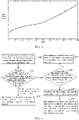
- the open circuit potential curve of the iron-lithium battery core is shown in FIG.2 .
- the open circuit potential curve of the ternary battery core is shown in FIG.3 .
- the slope of the open circuit potential curve of the iron-lithium battery core is greater than the slope of the open circuit potential curve of the ternary battery core under the state of charge of 0% to 8%, but the slope of the open circuit potential curve of the iron-lithium battery core is less than that of the ternary battery core under the state of charge of about 8% to 95%.
- the open circuit potential curve of the iron-lithium core shows a trend of steep rise and then smooth rise, the open circuit potential curve of the ternary core shows a trend of gradual rise.
- the power management controller 30 can collect the state parameters of each first battery cell 101 in the first battery core 10 and each second battery cell 201 in the second battery core 20, such as charging voltage, open circuit voltage, etc.
- the power management controller 30 can be directly connected to each battery cell via a wire or cable and collect the state parameters of each battery cell.
- the power management controller may not be directly connected to each battery cell, but rather collect the state parameters of each battery cell via wireless transmission technology.
- the battery module 1 can also include more components.
- it can also include a plurality of equalization units 40, each the equalization units 40 is disposed on one battery cell, and the power management controller 30 and each equalization unit 40 are electrically connected to control the equalization unit to perform equalization processing on the corresponding battery cell, where the equalization unit 40 can be a loss circuit, which can be used to lose the power of the connected battery cell under the control of the power management controller 30.
- the application scheme provides a method for equalizing a battery module, which is used to equalize the aforementioned battery modules with different kinds of battery cores.
- the execution subject of this method can be the power management controller in the battery module.
- the method includes the following steps:
- the power management controller can obtain a first charging voltage of each battery cell in the first battery core and a second charging voltage of each battery cell in the second battery core during charging. Furthermore, the power management controller can obtain the maximum and minimum value of the first charging voltage in the first battery core, and the maximum and minimum value of the second charging voltage in the second battery core.
- the first preset value can be determined according to the fully-charged voltage of the first battery core minus the first set value
- the second preset value can be determined according to fully-charged voltage of the second battery core minus the second set value, thus it can determine whether the first battery core enters its corresponding first fully-charged interval according to whether the maximum value of the first charging voltage in the first battery core is greater than the first preset value.
- the maximum value of the first charging voltage is greater than the first preset value, it indicates that the first battery core is close to the state of fully-charged and enters the corresponding first fully-charged interval.
- the maximum value of the first charging voltage is less than the first preset value, it indicates that the first battery core isn't still close to the state of fully-charged and doesn't enter the corresponding first fully-charged interval.
- whether the second battery core enters its corresponding second fully-charged interval can be determined according to whether the maximum value of the second charging voltage in the second battery core is greater than the second preset value.
- the first battery core and the second battery core are different kinds of battery core s, the scopes of their fully-charged range interval are also different. Therefore, the first preset value and the second preset value in an embodiment of the application can be designed as different. Of course, it doesn't exclude some special circumstances where the fully-charged voltage of the first battery core minus the first set value is just the same as the fully-charged voltage of the second battery core minus the second set value. Such special circumstances are also within the scope of protection of this application.
- step S402 the first battery core has entered its corresponding first fully-charged interval, indicating that the first battery core has nearly reached fully charged, and at this time, the second battery core has not yet entered its corresponding second fully-charged interval indicating that the second battery core still has not reached a state of fully-charged.
- the first battery core is discharged so that the power capacity charged in the first battery core is consumed under a certain extent, and then it slows down the charging speed of the first battery core until the second battery core enters its corresponding second fully-charged interval, and stops discharging consumption on the first battery core and the equalization comes to an end.
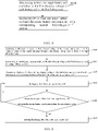
- the first battery core is discharged in step S402 until the second battery core enters its corresponding second fully-charged interval, and it can be implemented as follows, as shown in FIG.5 , including:
- partial battery cells are selected in a plurality of battery cells in the first battery core to perform discharging, and realizes the first battery core is discharged.
- the target battery cell is discharged in step S501 means charging of the target battery cell while and the discharge consumption is performed, for example, loss circuit is used to consume the charge of the target battery cell and so on.
- the target cell in step 500 can be randomly selected according to the preset number.
- the following method will be introduced to select target battery cell based on the charging voltage of a plurality of battery cells in the first battery core. As shown in FIG.6 , the method includes the following steps:
- the first charging voltage is greater than the fourth preset value indicates that the charging voltage of the corresponding battery cell is higher than the rest of battery cells, in order to make different battery cells in the first battery core voltage tends to be consistent, and therefore, select the battery cell whose the first charging voltage is greater than the fourth preset value to discharge.
- C is the fourth preset value
- A is the full-charged voltage pressure of the first battery core
- B is the voltage difference value
- a and b are constants.
- Step S501 can include the following steps:
- the present embodiment can find that the battery module enters a equalization state in time, and stop discharging the battery cell to save electric energy.
- the third preset value is determined by the fully-charged voltage of the first battery core and the third set value.
- the third preset value is smaller than the first preset value, and thus when the maximum value of the first charging voltage in the first battery core is less than the third preset value, it indicates that there has a not small voltage difference from which the first battery core enters the fully-charged interval; when the maximum value of the first charging voltage in the first battery core is greater than the third preset value, it indicates that there has a small voltage difference from which the first battery core enters the fully-charged interval;
- step S403 proceeds to step S404, and the second battery core is discharged until the first battery core enters its corresponding first fully-charged interval.
- the process of discharging the first battery core can be referred to step S402, and details are not described again.
- step S403 When a larger voltage difference from which the first battery core enters the fully-charged interval is determined by step S403, if step S404 is still performed to discharge the second battery core, and then the second battery core need a longer time to discharge, which is not unfriendly to charge the second battery core and the overall charging time of the battery module is also longer.
- the application provides the following battery method for equalizing.
- step S405 is performed to rest the first battery core and the second battery core, and stop charging the first battery core and the second battery core during the period of resting. Its purpose is to obtain the open circuit voltage of each battery cell in the first battery core or the second battery core under the state of resting, and then find the SOC corresponding to each battery cell in the open circuit potential curve corresponding to the battery cell based on the open circuit voltage, where SOC refers to the state of charge of a battery cell, which can be found through the open circuit voltage and open circuit potential curve. For example, the open circuit voltage (ordinate) of some battery cell and the open circuit potential curve are obtained in FIG.2 . Then the corresponding SOC (abscissa) of the open circuit voltage can be obtained.
- the resting time can be set according to experience, or, the resting time can also be set according to parameters such as the temperature of the first core and the second battery core, voltage of the battery core.
- step S406 is performed to discharge both the first battery core and the second battery core after resting until the SOC of each battery cell in the first battery core and the second battery core enters the same state, and realizes the equalization between the first battery core and the second battery core, where the SOC of each battery cell in the first battery core and the second battery core enters the same state, means that the SOC in the first battery core and the second battery core are the same or although the difference exists but the difference is within a preset range, and the preset range can be set to a smaller range, for example, the preset range is that the SOC difference between the first battery core and the second battery core is within 10%.
- step S406 may includes the following steps:
- step S700 since the first battery core and the second battery core have stopped being charged, the SOC value of each battery cell in the first battery core can be calculated according to the open circuit voltage of each battery cell in the first battery core and the first open circuit potential curve of the first battery core, and then the minimum SOC value among the SOC values of each battery cell in the first battery core.
- step S701 each battery cell other than the battery cell corresponding to a minimum SOC value in the first battery core are discharged until the SOC of these battery cores drops to the minimum SOC value, and realize the alignment of each battery core in the first battery core.
- the discharge capacity is determined according to the minimum SOC value in the first battery core and the discharge capacity, and it is used to discharge capacity each battery core in the second battery core.
- the discharge capacity can be calculated according to the minimum SOC value of the first battery core and the rated capacity of the second battery core.
- the discharge capacity of the second battery core that needs to be discharged can be obtained through the minimum SOC value of the first battery core so that the SOC of the second battery core is close to the minimum SOC of the first battery core after the second battery core is discharged based on the discharge capacity. Finally, the first battery core and the second battery core are under more equalized state.
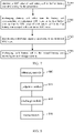
- FIG.8 shows a schematic structural diagram of an equalizing apparatus of a battery module provided by an embodiment of the application.
- the apparatus corresponds to the method embodiment executed by the power management controller in FIG.4 to FIG.7 and can execute the steps involved in the method executed by the power management controller in the above embodiment.
- the apparatus includes at least one software function module, the at least one software function module can be stored in a memory in the form of software or firmware, or can be solidified in an operating system(operating system, OS) of the apparatus.
- the apparatus includes: an obtaining module 800, configured to obtain a first charging voltage of each battery cell in the first battery core and a second charging voltage of each battery cell in the second battery core; a judgment module 801, configured to judge whether a maximum value of the first charging voltage of each battery cell in the first battery core is greater than a first preset value to determine whether the first battery core enters its corresponding first fully-charged interval, and judge whether a maximum value of the second charging voltage of each battery cell in the second battery core is greater than a second preset value to determine whether the second battery core enters its corresponding second fully-charged interval; a discharge module 802, configured to discharge the first battery core until the second battery core enters its corresponding second fully-charged interval after the judgment module 801 judges that the first battery core enters its corresponding first fully-charged interval and the second battery core doesn't enter its corresponding second fully-charged interval; the obtaining module 800, is configured to obtain a maximum value of the first charging voltage after the judgment module 801 judges that the first battery core doesn't enter
- the discharge module 802 is specifically configured to determine at least one target battery cell according to the first charging voltage of each battery cell in the first battery core; and to discharge at least one target battery cell until the second battery core enters its corresponding fully-charged interval.
- the discharge module 802 is further configured to obtain a SOC value of each battery cell in the first battery core after resting the preset time; and discharge each battery cell other than the battery cell corresponding to a minimum SOC value in the first battery core, so that the SOC value of each battery cell in the first battery core is equal to the minimum SOC value; and determine a discharge capacity according to the minimum SOC value; and discharge each battery cell in the second battery core according to the discharge capacity.
- the equalizing apparatus of the above battery module can adopt different equalization strategies according to the difference between the two different kinds of battery cores in the battery module entering the full charging interval, and improve equalizing accuracy of the two different kinds of battery cores in the battery module in order to avoid the occurrence of overcharge/overdischarge, and further to improve the life of the battery module.
- the implementation of each module in the equalizing apparatus of the battery module can refer to the implementation of the corresponding steps in the method for equalizing the battery module.
- the present application provides a power management controller.
- the power management controller has a chip 9, and an instruction is solidified in the chip 9.
- the instruction is executed by the chip to execute the equalizing method according to any one of optional implementation manners of the first aspect and any one of an optional implementation manner of the first aspect.
- the chip 9 specifically includes: a processor 901 and a memory 902.
- the processor 901 and the memory 902 are interconnected through a communication bus 903 and/or other forms of connection mechanism (not shown) and communicate with each other.
- the memory 902 stores a computer program executable by the processor 901.
- the processor 901 executes the computer program to execute the method process in any one of the foregoing implementation manners during execution, such as step S400 to step S406: obtaining a first charging voltage of each battery cell in the first battery core and a second charging voltage of each battery cell in the second battery core; judging whether the first battery core enters its corresponding first fully-charged interval and judging whether the second battery core enters its corresponding second fully-charged interval; if the first battery core enters its corresponding first fully-charged interval and the second battery core doesn't enter its corresponding second fully-charged interval, discharging the second battery core by the power management controller until the first battery core enters its corresponding first fully-charged interval; if the first battery core doesn't enter its corresponding first fully-charged interval and the second battery core enters its corresponding second fully-charged interval, judging whether the maximum value of the first charging voltage of each battery cell in the first battery core is greater than a third preset value; if so, discharging the
- the present application provides a storage medium with a computer-executable instruction stored therein, the computer-executable instruction executes the steps in any one of an optional implementations the above-mentioned equalizing method, when executed by the processor.
- the storage medium can be implemented by any type of volatile or nonvolatile storage apparatuses or their combination, such as Static Random Access Memory(Static Random Access Memory, SRAM), Electrically Erasable Programmable Read-Only Memory(Electrically Erasable Programmable Read-Only Memory, EEPROM), Erasable Programmable Read Only Memory(Erasable Programmable Read Only Memory, EPROM), Programmable Read-Only Memory(Programmable Read-Only Memory, PROM), Read-Only Memory(Read-Only Memory, ROM), magnetic memory, flash memory, magnetic disk or optical disk.
- Static Random Access Memory Static Random Access Memory, SRAM
- Electrically Erasable Programmable Read-Only Memory Electrically Erasable Programmable Read-Only Memory
- EEPROM Electrically Erasable Programmable Read-Only Memory
- EPROM Erasable Programmable Read Only Memory
- PROM Programmable Read-Only Memory
- Read-Only Memory Read-Only Memory
- magnetic memory flash memory
- flash memory magnetic disk
- the present application provides a computer program product, the computer program product, when executed by a computer, causes the computer to execute the method process in any of the foregoing implementation manners.
Landscapes
- Engineering & Computer Science (AREA)
- Power Engineering (AREA)
- General Chemical & Material Sciences (AREA)
- Electrochemistry (AREA)
- Chemical Kinetics & Catalysis (AREA)
- Chemical & Material Sciences (AREA)
- Manufacturing & Machinery (AREA)
- Sustainable Development (AREA)
- Mechanical Engineering (AREA)
- Transportation (AREA)
- Sustainable Energy (AREA)
- Life Sciences & Earth Sciences (AREA)
- Microelectronics & Electronic Packaging (AREA)
- Charge And Discharge Circuits For Batteries Or The Like (AREA)
- Secondary Cells (AREA)
Abstract
Description
- This present application relates to the technical field of battery equalization, and in particular, to a method and apparatus for equalizing the battery module, a battery module, and a power management controller.
- Battery equalization refers to the use of power electronics technology to keep lithium-ion battery cell voltage or the voltage deviation of battery module within the expected range, so as to ensure that each single battery in the battery module maintains the same state during use in order to avoid the occurrence of overcharge/overdischarge, and further to improve the life of the battery module.
- Existing battery equalization methods are generally based on voltage for charge and discharge equalization, but such equalization methods are only suitable for a single type of battery core. A single type of battery cell means that each single battery in the battery module belongs to the same type (such as it is a ternary battery core or an iron-lithium battery core), and for a battery module with two kinds of battery cores (such as with both an iron-lithium battery core and a ternary battery core at the same time). Due to the different characteristics of different kinds of battery cores, their fully-charged voltages are also different, so the battery equalization method based on a single type of battery core has poor accuracy for equalizing a battery module with two kinds of battery cores.
- The purpose of the embodiment of the present application is to provide a method for equalizing, apparatus, a battery module, and a power management controller, so as to solve the problem of poor accuracy in equalizing battery modules with two kinds of battery cores.
- In a first aspect, the invention provides a method for equalizing a battery module, the battery module including a first battery core, a second battery core and a power management controller, the first battery core and the second battery core being connected in series, both the first battery core and the second battery core including at least one battery cell, the first battery core having a first battery chemical component and exhibiting a first open circuit potential curve, the second battery core having a second battery chemical component and exhibiting a second open potential curve, and the first open circuit potential curve being different from the second open circuit potential curve, the method including : obtaining, by the power management controller, a first charging voltage of each battery cell in the first battery core and a second charging voltage of each battery cell in the second battery core; judging, by the power management controller, whether a maximum value of the first charging voltage of each battery cell in the first battery core is greater than a first preset value to determine whether the first battery core enters a corresponding first fully-charged interval; judging, by the power management controller, whether a maximum value of the second charging voltage of each battery cell in the second battery core is greater than a second preset value to determine whether the second battery core enters a corresponding second fully-charged interval; if the first battery core enters its corresponding first fully-charged interval and the second battery core doesn't enter its corresponding second fully-charged interval, discharging the first battery core by the power management controller until the second battery core enters its corresponding second fully-charged interval; if the first battery core doesn't enter its corresponding first fully-charged interval and the second battery core enters its corresponding second fully-charged interval, obtaining the maximum value of the first charging voltage, judging whether the maximum value of the first charging voltage of each battery cell in the first battery core is greater than a third preset value by the power management controller; and if so, discharging the second battery core by the power management controller until the first battery core enters its corresponding first fully-charged interval; if not, controlling the first battery core and the second battery core to rest for a preset time by the power management controller; after resting for the preset time, discharging the first battery core and the second battery core by the power management controller until a SOC of each battery cell in the first battery core and the second battery core enters a same state.
- In the above-designed method for equalizing, firstly obtaining a first charging voltage of each battery cell in the first battery core and a second charging voltage of each battery cell in the second battery core, and then judging whether a maximum value of the first charging voltage of each battery cell in the first battery core is greater than a first preset value to determine whether the first battery core enters a corresponding first fully-charged interval, and judging whether a maximum value of the second charging voltage of each battery cell in the second battery core is greater than a second preset value to determine whether the second battery core enters its corresponding second fully-charged interval. When the first battery core enters its corresponding first fully-charged interval and the second battery core doesn't enter its corresponding second fully-charged interval, discharging the first battery core until the second battery core enters its corresponding second fully-charged interval. So as to solve the equalizing problem of the first battery core and the second battery core when the first battery core enters its corresponding first fully-charged interval and the second battery core doesn't enter its corresponding second fully-charged interval. When the first battery core doesn't enter its corresponding first fully-charged interval and the second battery core enters its corresponding second fully-charged interval, judging whether the maximum value of the first charging voltage of each battery cell in the first battery core is greater than a third preset value. And if so, discharging the second battery core until the first battery core enters its corresponding first fully-charged interval; if not, controlling the first battery core and the second battery core to rest for a preset time. After resting for the preset time, discharging the first battery core and the second battery core by the power management controller, until a SOC of each battery cell in the first battery core and the second battery core enters the same state, so as to solve the equalizing problem when the first battery core doesn't enter its corresponding first fully-charged interval and the second battery core enters its corresponding second fully-charged interval, realizing the equalization method of two different kinds of battery cores in the battery module, and solving the problem that the equalization of battery modules with two different kinds of battery cores is not accurate when using the existing voltage based charge and discharge equalization, and improving the accuracy of the equalization of battery modules with two different kinds of battery cores.
- In an optional implementation manner of the first aspect, discharging the first battery core until the second battery core enters its corresponding fully-charged interval, includes: determining at least one target battery cell according to the first charging voltage of each battery cell in the first battery core; discharging the at least one target battery cell until the second battery core enters its corresponding second fully-charged interval.
- In an optional implementation manner of the first aspect, determining at least one target battery cell according to the first charging voltage of each battery cell in the first battery core, includes: calculating a difference between a fully-charged voltage of the second battery core and a minimum value of the second charging voltage in the second battery core to obtain a voltage difference value; determining a fourth preset value according to a fully-charged voltage of the first battery core and the voltage difference value; determining a battery cell with a first charging voltage in the first battery core is greater than the fourth preset value as a target battery cell to obtain the at least one target battery cell.
- In an optional implementation manner of the first aspect, discharging the at least one target battery cell by the power management controller until the second battery core enters its corresponding second fully-charged interval, includes: discharging the at least one target battery cell; judging whether a maximum value of the second charging voltage in the battery cell is greater than the second preset value, during discharging of the at least one target battery cell; if so, stopping discharging the at least one target battery cell by the power management controller.
- In an optional implementation manner of the first aspect, after resting for the preset time, discharging the first battery core and the second battery core until a SOC of each battery cell in the first battery core and the second battery core entering a same state, includes: obtaining a SOC value of each battery cell in the first battery core after resting the preset time; discharging a battery cell other than the battery cell corresponding to a minimum SOC value in the first battery core, so that the SOC value of each battery cell in the first battery core is equal to the minimum SOC value; determining a discharge capacity according to the minimum SOC value; discharging each battery cell in the second battery core according to the discharge capacity.
- In an optional implementation manner of the first aspect, determining a discharge capacity according to the minimum SOC value by the power management controller, includes: obtaining a rated capacity of the second battery core; calculating the discharge capacity according to the minimum SOC value and the rated capacity of the second battery core.
- In a second aspect, the invention provides an equalizing apparatus of a battery module, the battery module including a first battery core, a second battery core and a power management controller, the first battery core and the second battery core being connected in series, both the first battery core and the second battery core including at least one battery cell and the first battery core having a first battery chemical component and exhibiting a first open circuit potential curve, the second battery core having a second battery chemical component and exhibiting a second open potential curve, and the first open circuit potential curve being different from the second open circuit potential curve, the apparatus including: an obtaining module, configured to obtain a first charging voltage of each battery cell in the first battery core and a second charging voltage of each battery cell in the second battery core; a judgment module, configured to judge whether a maximum value of the first charging voltage of each battery cell in the first battery core is greater than a first preset value to determine whether the first battery core enters its corresponding first fully-charged interval; the judgment module further configured to judge whether a maximum value of the second charging voltage of each battery cell in the second battery core is greater than a second preset value to determine whether the second battery core enters its corresponding second fully-charged interval; a discharge module, configured to discharge the first battery core until the second battery core enters its corresponding second fully-charged interval after the judgment module judges that the first battery core enters its corresponding first fully-charged interval and the second battery core doesn't enter its corresponding second fully-charged interval; the obtaining module, further configured to obtain the maximum value of the first charging voltage after the judgment module judges that the first battery core doesn't enter its corresponding first fully-charged interval and the second battery core enters its corresponding second fully-charged interval; the judgment module, further configured to judge whether the maximum value of the first charging voltage of each battery cell in the first battery core is greater than a third preset value; the discharge module configured to discharge the second battery core until the first battery core enters its corresponding first fully-charged interval after the judgment module judges that the maximum value of the first charging voltage of each battery cell in the first battery core is greater than a third preset value; a resting module, configured to control the first battery core and the second battery core to rest for a preset time after the judgment module judges that a maximum first charging voltage is less than the third preset value; the discharge module further configured to discharge the first battery core and the second battery core until a SOC of each battery cell in the first battery core and the second battery core enters the same state after resting for the preset time.
- In the above-designed the equalizing apparatus, firstly obtaining a first charging voltage of each battery cell in the first battery core and a second charging voltage of each battery cell in the second battery core, and then judging whether a maximum value of the first charging voltage of each battery cell in the first battery core is greater than a first preset value to determine whether the first battery core enters its corresponding first fully-charged interval, and judging whether a maximum value of the second charging voltage of each battery cell in the second battery core is greater than a second preset value to determine whether the second battery core enters its corresponding second fully-charged interval. When the first battery core enters its corresponding first fully-charged interval and the second battery core doesn't enter its corresponding second fully-charged interval, discharging the first battery core until the second battery core enters its corresponding second fully-charged interval. So as to solve the equalizing problem of the first battery core and the second battery when the first battery core enters its corresponding first fully-charged interval and the second battery core doesn't enter its corresponding second fully-charged interval. When the first battery core doesn't enter its corresponding first fully-charged interval and the second battery core enters its corresponding second fully-charged interval, judging whether the maximum value of the first charging voltage of each battery cell in the first battery core is greater than a third preset value. And if so, discharging the second battery core until the first battery core enters its corresponding first fully-charged interval; if not, controlling the first battery core and the second battery core to rest for a preset time. After resting for the preset time, discharging the first battery core and the second battery core by the power management controller, so as to solve the equalizing problem when the first battery core doesn't enter its corresponding first fully-charged interval and the second battery core enters its corresponding second fully-charged interval, realizing the equalization method of two different kinds of battery cores in the battery module, and solving the problem that the equalization of battery modules with two different kinds of battery cores is not accurate when using the existing voltage based charge and discharge equalization, and improving the accuracy of the equalization of battery modules with two different kinds of battery cores.
- In a third aspect, the invention provides a battery module, the battery module including: a first battery core and a second battery core, the first battery core and the second battery core being connected in series, both the first battery core and the second battery core including at least one battery cell, and the charge and discharge curves of the first battery core and the second battery core being different; a power management controller, configured to execute the method for equalizing according to an optional implementation manner of the first aspect to perform equalization processing on the first battery core and the second battery core.
- In an optional implementation manner of the third aspect, the battery module further includes: a plurality of equalization units, each the equalization units being disposed on one battery cell, the power management controller and each equalization units being electrically connected to control the equalization unit to perform equalization processing on the corresponding battery cell.
- In a fourth aspect, the invention provides a power management controller, the power management controller including a chip, an instruction is solidified in the chip, the instruction, when executed by the chip, executes the method for equalizing according to the first aspect and any one of an optional implementation manner of the first aspect.
- In a fifth aspect, the present application provides a storage medium with a computer-executable instruction stored therein, the computer-executable instruction executes the method in the first aspect, any one of an optional implementation manner of the first aspect, when executed by the processor.
- In a sixth aspect, the present application provides a computer program product, the computer program product, when executed by a computer, causes the computer to execute the method in the first aspect, in any one of an optional implementations of the first aspect.
- In order to illustrate the technical solutions in embodiments of the present application more clearly, brief description will be made below to drawings required in the embodiments of the present application, and apparently, the drawings described below are some embodiments of the present application only, and other drawings could be obtained based on these drawings by those ordinary skilled in this art without creative efforts.
-
FIG.1 is a schematic structural diagram of a battery module provided by an embodiment of the application; -
FIG.2 is a schematic diagram of a charging curve of a first battery core provided by an embodiment of the application; -
FIG.3 is a schematic diagram of a charging curve of a second battery core provided by an embodiment of the application; -
FIG.4 is a first flowchart of a method for equalizing provided by an embodiment of the application; -
FIG.5 is a second flowchart of the method for equalizing provided by an embodiment of the application; -
FIG.6 is a third flowchart of the method for equalizing provided by an embodiment of the application; -
FIG.7 is a fourth flowchart of the method for equalizing provided by an embodiment of the application; -
FIG.8 is a schematic structural diagram of an equalizing apparatus provided by an embodiment of the application; -
FIG.9 is a schematic structural diagram of a chip provided by an embodiment of the application. - In the drawings, the drawings are not drawn to actual scale.
- Description of reference signs: 1-battery module; 10-first battery core; 101-first battery cell; 20-second battery core; 201-second battery cell; 30-power management controller; 40-equalization unit; 800-obtaining module; 801-judgment module; 802-discharge module;803-resting module; 9-chip; 901-processor; 902-memory; 903-communication bus.
- Implementation manners of the present application will be further described below in detail with reference to the accompanying drawings and embodiments. The detailed description of the following embodiments and the accompanying drawings are used to exemplarily illustrate principles of the present application, but cannot be used to limit the scope of the present application, that is, the present application is not limited to the described embodiments.
- In the description of the present application, it should be noted that, unless otherwise provided, "a plurality of' means more than two; and orientations or positional relationships indicated by terms such as "up", "down", "left", "right", "inside", and "outside" are merely for convenience of describing the present application and for simplifying the description, rather than for indicating or implying that an apparatus or element indicated must have a specific orientation, and must be constructed and operated in a specific orientation, which thus may not be understood as limitation to the present application. In addition, the terms "first", "second", and "third" are only intended for the purpose of description, and shall not be understood as an indication or implication of relative importance. "Vertical" is not strictly vertical, but within an allowable range of error. "Parallel" is not strictly parallel, but within an allowable range of error.
- The orientation words appearing in the following description are all directions shown in the drawings, and do not limit the specific structure of the present application. In the description of the present application, it should be further noted that, unless explicitly specified and defined otherwise, terms "installation", "interconnection", and "connection" should be understood broadly, for example, they may either be a fixed connection, or a detachable connection, or an integrated connection; and they may either be a direct connection, or an indirect connection through an intermediary. Those of ordinary skill in the art may understand the specific meanings of the foregoing terms in the present application according to specific conditions.
-
FIG. 1 shows an example of abattery module 1 according to the present application, thebattery module 1 includes afirst battery core 10, asecond battery core 20, and apower management controller 30, thefirst battery core 10 and thesecond battery core 20 are connected in series, thefirst battery core 10 includes at least onefirst battery cell 101 and thesecond battery core 20 includes at least onesecond battery cell 201. The first battery core has a first battery chemical component and exhibits a first open circuit potential curve, and the second battery core has a second battery chemical component and exhibits a second open potential curve. The first open circuit potential curve is different from the second open circuit potential curve. - The difference in open circuit potential curve of different kinds of battery cores will be described below. It is assumed that the
first battery core 10 is an iron-lithium battery core, thesecond battery core 20 is a ternary battery core. The open circuit potential curve of the iron-lithium battery core is shown inFIG.2 . The open circuit potential curve of the ternary battery core is shown inFIG.3 . Compared withFIG.2 andFIG.3 , it can be seen that the slope of the open circuit potential curve of the iron-lithium battery core is greater than the slope of the open circuit potential curve of the ternary battery core under the state of charge of 0% to 8%, but the slope of the open circuit potential curve of the iron-lithium battery core is less than that of the ternary battery core under the state of charge of about 8% to 95%. The open circuit potential curve of the iron-lithium core shows a trend of steep rise and then smooth rise, the open circuit potential curve of the ternary core shows a trend of gradual rise. - The
power management controller 30 can collect the state parameters of eachfirst battery cell 101 in thefirst battery core 10 and eachsecond battery cell 201 in thesecond battery core 20, such as charging voltage, open circuit voltage, etc. As a possible implementation, thepower management controller 30 can be directly connected to each battery cell via a wire or cable and collect the state parameters of each battery cell. As another possible implementation, the power management controller may not be directly connected to each battery cell, but rather collect the state parameters of each battery cell via wireless transmission technology. - In some possible implementations, the
battery module 1 can also include more components. For example, it can also include a plurality ofequalization units 40, each theequalization units 40 is disposed on one battery cell, and thepower management controller 30 and eachequalization unit 40 are electrically connected to control the equalization unit to perform equalization processing on the corresponding battery cell, where theequalization unit 40 can be a loss circuit, which can be used to lose the power of the connected battery cell under the control of thepower management controller 30. - Combined with the
battery module 1 as shown inFigure 1 , the application scheme provides a method for equalizing a battery module, which is used to equalize the aforementioned battery modules with different kinds of battery cores. The execution subject of this method can be the power management controller in the battery module. As shown inFIG.4 , the method includes the following steps: - Step S400: obtaining a first charging voltage of each battery cell in the first battery core and a second charging voltage of each battery cell in the second battery core.
- Step S401: judging whether the first battery core enters its corresponding first fully-charged interval and judging whether the second battery core enters its corresponding second fully-charged interval; if the first battery core enters its corresponding first fully-charged interval and the second battery core doesn't enter its corresponding second fully-charged interval, then proceeds to Step S402; if the first battery core doesn't enter its corresponding first fully-charged interval and the second battery core enters its corresponding second fully-charged interval, then proceeds to Step S403.
- Step S402: discharging the first battery core until the second battery core enters its corresponding second fully-charged interval.
- Step S403: judging whether the maximum value of the first charging voltage of each battery cell in the first battery core is greater than a third preset value; if so, proceeds to Step S404; if not, proceeds to step S405.
- Step S404: discharging the second battery core until the first battery core enters its corresponding first fully-charged interval;
- Step S405: controlling the first battery core and the second battery core to rest for a preset time, and then proceeds to Step S406.
- Step S406: after resting for the preset time, the power management controller discharging the first battery core and the second battery core until a SOC of each battery cell in the first battery core and the second battery core enters the same state.
- The implementation of the above steps will be described in detail below.
- In step S400, with reference to the description of the power management controller in
FIG.1 , the power management controller can obtain a first charging voltage of each battery cell in the first battery core and a second charging voltage of each battery cell in the second battery core during charging. Furthermore, the power management controller can obtain the maximum and minimum value of the first charging voltage in the first battery core, and the maximum and minimum value of the second charging voltage in the second battery core. - In step S401, the first preset value can be determined according to the fully-charged voltage of the first battery core minus the first set value, and the second preset value can be determined according to fully-charged voltage of the second battery core minus the second set value, thus it can determine whether the first battery core enters its corresponding first fully-charged interval according to whether the maximum value of the first charging voltage in the first battery core is greater than the first preset value. When the maximum value of the first charging voltage is greater than the first preset value, it indicates that the first battery core is close to the state of fully-charged and enters the corresponding first fully-charged interval. When the maximum value of the first charging voltage is less than the first preset value, it indicates that the first battery core isn't still close to the state of fully-charged and doesn't enter the corresponding first fully-charged interval. Similarly, whether the second battery core enters its corresponding second fully-charged interval can be determined according to whether the maximum value of the second charging voltage in the second battery core is greater than the second preset value.
- It should be noted that since the first battery core and the second battery core are different kinds of battery core s, the scopes of their fully-charged range interval are also different. Therefore, the first preset value and the second preset value in an embodiment of the application can be designed as different. Of course, it doesn't exclude some special circumstances where the fully-charged voltage of the first battery core minus the first set value is just the same as the fully-charged voltage of the second battery core minus the second set value. Such special circumstances are also within the scope of protection of this application.
- In step S402, the first battery core has entered its corresponding first fully-charged interval, indicating that the first battery core has nearly reached fully charged, and at this time, the second battery core has not yet entered its corresponding second fully-charged interval indicating that the second battery core still has not reached a state of fully-charged. At this time, the first battery core is discharged so that the power capacity charged in the first battery core is consumed under a certain extent, and then it slows down the charging speed of the first battery core until the second battery core enters its corresponding second fully-charged interval, and stops discharging consumption on the first battery core and the equalization comes to an end. When the equalization comes to an end, since the first battery core and the second battery core have entered their respective fully-charged interval to be close the state of fully-charged. Thus, when one battery core is fully charged, the other battery cell is also close to or has been fully charged, so as to achieve the equalization between the first battery core and the second battery core.
- As a possible embodiment, the first battery core is discharged in step S402 until the second battery core enters its corresponding second fully-charged interval, and it can be implemented as follows, as shown in
FIG.5 , including: - Step S500: determining at least one target battery cell according to the first charging voltage of each battery cell in the first battery core.
- Step S501: discharging the at least one target battery cell until the second battery core enters its corresponding second fully-charged interval.
- In the above solution, partial battery cells are selected in a plurality of battery cells in the first battery core to perform discharging, and realizes the first battery core is discharged. It should be understood that the target battery cell is discharged in step S501 means charging of the target battery cell while and the discharge consumption is performed, for example, loss circuit is used to consume the charge of the target battery cell and so on.
- There are a variety of ways to determine the target cell in
step 500, for example, it can be randomly selected according to the preset number. The following method will be introduced to select target battery cell based on the charging voltage of a plurality of battery cells in the first battery core. As shown inFIG.6 , the method includes the following steps: - Step S600: calculating a difference between the fully-charged voltage of the second battery core and the minimum value of the second charging voltage in the second battery core to obtain a voltage difference value.
- Step S601: determining the fourth preset value according to the fully-charged voltage of the first battery core and the voltage difference value.
- Step S602: determining a battery cell whose the first charging voltage in the first battery core is greater than the fourth preset value as a target battery cell to obtain the at least one target battery cell.
- In the above solution, the first charging voltage is greater than the fourth preset value indicates that the charging voltage of the corresponding battery cell is higher than the rest of battery cells, in order to make different battery cells in the first battery core voltage tends to be consistent, and therefore, select the battery cell whose the first charging voltage is greater than the fourth preset value to discharge.
- The following introduces a method for determining the fourth preset value according to a fully-charged voltage and the voltage difference value, which is expressed as the following formula:

- Where C is the fourth preset value, A is the full-charged voltage pressure of the first battery core, B is the voltage difference value, and a and b are constants.
- As a possible implementation manner, as shown in
FIG.6 , Step S501 can include the following steps: - Step S603: discharging the at least one target battery cell.
- Step S604: during discharging of the at least one target battery cell, the power management controller judging whether a maximum value of the second charging voltage in the second battery core is greater than the second preset value; if so, proceeds to Step S605; if not, proceeds to Step S603.
- Step S605: stopping discharging the at least one target battery cell.
- In the above solution, during discharging process of the target battery cell, it is possible to judge whether the maximum value of the second charging voltage in the second battery core is greater than the second preset value in accordance with a certain time interval, that is, judge whether the second battery core enters its corresponding second fully-charged interval, if the second battery core doesn't enter its corresponding second fully-charged interval, then continue discharging the target battery cell; if the second battery core enters its corresponding second fully-charged interval, then stop discharging the target battery cell. The present embodiment can find that the battery module enters a equalization state in time, and stop discharging the battery cell to save electric energy.
- The solution that the first battery core enters its corresponding first fully-charged interval and the second battery core doesn't enter its corresponding first fully-charged interval is described above. The following continues to introduce the solution when the first battery core doesn't enter its corresponding first fully-charged interval while the second battery core enters its corresponding first fully-charged interval, which is included in steps S403 to S406.
- In step S403, the third preset value is determined by the fully-charged voltage of the first battery core and the third set value. The third preset value is smaller than the first preset value, and thus when the maximum value of the first charging voltage in the first battery core is less than the third preset value, it indicates that there has a not small voltage difference from which the first battery core enters the fully-charged interval; when the maximum value of the first charging voltage in the first battery core is greater than the third preset value, it indicates that there has a small voltage difference from which the first battery core enters the fully-charged interval;
When a smaller voltage difference from which the first battery core enters the fully-charged interval is determined by step S403, proceeds to step S404, and the second battery core is discharged until the first battery core enters its corresponding first fully-charged interval. The process of discharging the first battery core can be referred to step S402, and details are not described again. - When a larger voltage difference from which the first battery core enters the fully-charged interval is determined by step S403, if step S404 is still performed to discharge the second battery core, and then the second battery core need a longer time to discharge, which is not unfriendly to charge the second battery core and the overall charging time of the battery module is also longer. In response to this situation, the application provides the following battery method for equalizing.
- Firstly, step S405 is performed to rest the first battery core and the second battery core, and stop charging the first battery core and the second battery core during the period of resting. Its purpose is to obtain the open circuit voltage of each battery cell in the first battery core or the second battery core under the state of resting, and then find the SOC corresponding to each battery cell in the open circuit potential curve corresponding to the battery cell based on the open circuit voltage, where SOC refers to the state of charge of a battery cell, which can be found through the open circuit voltage and open circuit potential curve. For example, the open circuit voltage (ordinate) of some battery cell and the open circuit potential curve are obtained in
FIG.2 . Then the corresponding SOC (abscissa) of the open circuit voltage can be obtained. The resting time can be set according to experience, or, the resting time can also be set according to parameters such as the temperature of the first core and the second battery core, voltage of the battery core. - Then, step S406 is performed to discharge both the first battery core and the second battery core after resting until the SOC of each battery cell in the first battery core and the second battery core enters the same state, and realizes the equalization between the first battery core and the second battery core, where the SOC of each battery cell in the first battery core and the second battery core enters the same state, means that the SOC in the first battery core and the second battery core are the same or although the difference exists but the difference is within a preset range, and the preset range can be set to a smaller range, for example, the preset range is that the SOC difference between the first battery core and the second battery core is within 10%.
- As a possible embodiment, as shown in
FIG.7 , step S406 may includes the following steps: - Step S700: obtaining a SOC value of each battery cell in the first battery core after resting for the preset time.
- Step S701: discharging a battery cell other than the battery cell corresponding to a minimum SOC value in the first battery core, so that the SOC value of each battery cell in the first battery core is equal to the minimum SOC value.
- Step S702: determining a discharge capacity according to the minimum SOC value.
- Step S703: discharging each battery cell in the second battery core according to the discharge capacity.
- In step S700, since the first battery core and the second battery core have stopped being charged, the SOC value of each battery cell in the first battery core can be calculated according to the open circuit voltage of each battery cell in the first battery core and the first open circuit potential curve of the first battery core, and then the minimum SOC value among the SOC values of each battery cell in the first battery core.
- In step S701, each battery cell other than the battery cell corresponding to a minimum SOC value in the first battery core are discharged until the SOC of these battery cores drops to the minimum SOC value, and realize the alignment of each battery core in the first battery core.
- In step S702, the discharge capacity is determined according to the minimum SOC value in the first battery core and the discharge capacity, and it is used to discharge capacity each battery core in the second battery core. In a possible implementation manner, the discharge capacity can be calculated according to the minimum SOC value of the first battery core and the rated capacity of the second battery core. For example, the discharge capacity can be calculated by the following formula, which is: discharge capacity = (1-Minimum SOC value) ∗ rated capacity of the second battery core.
- In the above solution, the discharge capacity of the second battery core that needs to be discharged can be obtained through the minimum SOC value of the first battery core so that the SOC of the second battery core is close to the minimum SOC of the first battery core after the second battery core is discharged based on the discharge capacity. Finally, the first battery core and the second battery core are under more equalized state.
- In the above-mentioned embodiment provided by this application, for the battery module with two different kinds of battery cores, according to the difference between the two battery cores entering the fully-charged interval, different equalization strategies are used to improve equalizing accuracy of the two different kinds of battery cores in the battery module in order to avoid the occurrence of overcharge/overdischarge, and further to improve the life of the battery module.
-
FIG.8 shows a schematic structural diagram of an equalizing apparatus of a battery module provided by an embodiment of the application. It should be understood that the apparatus corresponds to the method embodiment executed by the power management controller inFIG.4 to FIG.7 and can execute the steps involved in the method executed by the power management controller in the above embodiment. The apparatus includes at least one software function module, the at least one software function module can be stored in a memory in the form of software or firmware, or can be solidified in an operating system(operating system, OS) of the apparatus. The apparatus includes: an obtaining module 800, configured to obtain a first charging voltage of each battery cell in the first battery core and a second charging voltage of each battery cell in the second battery core; a judgment module 801, configured to judge whether a maximum value of the first charging voltage of each battery cell in the first battery core is greater than a first preset value to determine whether the first battery core enters its corresponding first fully-charged interval, and judge whether a maximum value of the second charging voltage of each battery cell in the second battery core is greater than a second preset value to determine whether the second battery core enters its corresponding second fully-charged interval; a discharge module 802, configured to discharge the first battery core until the second battery core enters its corresponding second fully-charged interval after the judgment module 801 judges that the first battery core enters its corresponding first fully-charged interval and the second battery core doesn't enter its corresponding second fully-charged interval; the obtaining module 800, is configured to obtain a maximum value of the first charging voltage after the judgment module 801 judges that the first battery core doesn't enter its corresponding first fully-charged interval and the second battery core enters its corresponding second fully-charged interval; the judgment module 801, further configured to judge whether the maximum value of the first charging voltage of each battery cell in the first battery core is greater than a third preset value; the discharge module 802, is configured to discharge the second battery core until the first battery core enters its corresponding first fully-charged interval after the judgment module 801 judges that the maximum value of the first charging voltage of each battery cell in the first battery core is greater than a third preset value; a resting module 803, configured to control the first battery core and the second battery core to rest for a preset time after the judgment module 801 judges that a maximum first charging voltage is less than the third preset value; and the discharge module 802, further configured to discharge the first battery core and the second battery core until a SOC of each battery cell in the first battery core and the second battery core enters a same state after resting for the preset time. - In some optional embodiment, the
discharge module 802 is specifically configured to determine at least one target battery cell according to the first charging voltage of each battery cell in the first battery core; and to discharge at least one target battery cell until the second battery core enters its corresponding fully-charged interval. - In some optional embodiment, the
discharge module 802 is further configured to obtain a SOC value of each battery cell in the first battery core after resting the preset time; and discharge each battery cell other than the battery cell corresponding to a minimum SOC value in the first battery core, so that the SOC value of each battery cell in the first battery core is equal to the minimum SOC value; and determine a discharge capacity according to the minimum SOC value; and discharge each battery cell in the second battery core according to the discharge capacity. - The equalizing apparatus of the above battery module can adopt different equalization strategies according to the difference between the two different kinds of battery cores in the battery module entering the full charging interval, and improve equalizing accuracy of the two different kinds of battery cores in the battery module in order to avoid the occurrence of overcharge/overdischarge, and further to improve the life of the battery module. Where the implementation of each module in the equalizing apparatus of the battery module can refer to the implementation of the corresponding steps in the method for equalizing the battery module.
- As shown in
FIG.9 , the present application provides a power management controller. The power management controller has a chip 9, and an instruction is solidified in the chip 9. The instruction is executed by the chip to execute the equalizing method according to any one of optional implementation manners of the first aspect and any one of an optional implementation manner of the first aspect. The chip 9 specifically includes: aprocessor 901 and amemory 902. Theprocessor 901 and thememory 902 are interconnected through acommunication bus 903 and/or other forms of connection mechanism (not shown) and communicate with each other. Thememory 902 stores a computer program executable by theprocessor 901. When the computing apparatus is running, the processor 901 executes the computer program to execute the method process in any one of the foregoing implementation manners during execution, such as step S400 to step S406: obtaining a first charging voltage of each battery cell in the first battery core and a second charging voltage of each battery cell in the second battery core; judging whether the first battery core enters its corresponding first fully-charged interval and judging whether the second battery core enters its corresponding second fully-charged interval; if the first battery core enters its corresponding first fully-charged interval and the second battery core doesn't enter its corresponding second fully-charged interval, discharging the second battery core by the power management controller until the first battery core enters its corresponding first fully-charged interval; if the first battery core doesn't enter its corresponding first fully-charged interval and the second battery core enters its corresponding second fully-charged interval, judging whether the maximum value of the first charging voltage of each battery cell in the first battery core is greater than a third preset value; if so, discharging the second battery core until the first battery core enters its corresponding first fully-charged interval; if not, controlling the first battery core and the second battery core to rest for a preset time; after resting for the preset time, discharging the first battery core and the second battery core by the power management controller until a SOC of each battery cell in the first battery core and the second battery core enters a same state. - The present application provides a storage medium with a computer-executable instruction stored therein, the computer-executable instruction executes the steps in any one of an optional implementations the above-mentioned equalizing method, when executed by the processor.
- Where the storage medium can be implemented by any type of volatile or nonvolatile storage apparatuses or their combination, such as Static Random Access Memory(Static Random Access Memory, SRAM), Electrically Erasable Programmable Read-Only Memory(Electrically Erasable Programmable Read-Only Memory, EEPROM), Erasable Programmable Read Only Memory(Erasable Programmable Read Only Memory, EPROM), Programmable Read-Only Memory(Programmable Read-Only Memory, PROM), Read-Only Memory(Read-Only Memory, ROM), magnetic memory, flash memory, magnetic disk or optical disk.
- The present application provides a computer program product, the computer program product, when executed by a computer, causes the computer to execute the method process in any of the foregoing implementation manners.
- Although the present application has been described with reference to the preferred embodiments, various modifications can be made to it without departing from the scope of the present application and the components therein can be replaced with equivalents. In particular, as long as there is no structural conflict, the various technical features mentioned in the various embodiments can be combined in any manner. This application is not limited to the specific embodiments disclosed in the text, but includes all technical solutions falling within the scope of the claims.
Claims (10)
- A method for equalizing a battery module, the battery module comprising a first battery core, a second battery core, and a power management controller, the first battery core and the second battery core being connected in series, both the first battery core and the second battery core comprising at least one battery cell, the first battery core having a first battery chemical component and exhibiting a first open circuit potential curve, the second battery core having a second battery chemical component and exhibiting a second open circuit potential curve, and the first open circuit potential curve being different from the second open circuit potential curve, the method comprising:obtaining, by the power management controller, a first charging voltage of each battery cell in the first battery core and a second charging voltage of each battery cell in the second battery core;Judging, by the power management controller, whether a maximum value of the first charging voltage of each battery cell in the first battery core is greater than a first preset value to determine whether the first battery core enters a corresponding first fully-charged interval;judging, by the power management controller, whether a maximum value of the second charging voltage of each battery cell in the second battery core is greater than a second preset value to determine whether the second battery core enters its corresponding second fully-charged interval;if the first battery core enters its corresponding first fully-charged interval and the second battery core does not enter its corresponding second fully-charged interval, discharging the first battery core by the power management controller until the second battery core enters its corresponding second fully-charged interval;if the first battery core does not enter its corresponding first fully-charged interval and the second battery core enters its corresponding second fully-charged interval, judging whether the maximum value of the first charging voltage of each battery cell in the first battery core is greater than a third preset value by the power management controller;and if so, discharging the second battery core by the power management controller until the first battery core enters its corresponding first fully-charged interval;if not, controlling the first battery core and the second battery core to rest for a preset time by the power management controller;after resting for the preset time, discharging the first battery core and the second battery core by the power management controller until a SOC of each battery cell in the first battery core and the second battery core enters a same state.
- The method according to claim 1, wherein discharging the first battery core by the power management controller until the second battery core enters its corresponding fully-charged interval, comprises:determining, by the power management controller, at least one target battery cell according to the first charging voltage of each battery cell in the first battery core;discharging, by the power management controller, the at least one target battery cell until the second battery core enters its corresponding second fully-charged interval.
- The method according to claim 2, wherein determining at least one target battery cell according to the first charging voltage of each battery cell in the first battery core by the power management controller, comprises:calculating, by the power management controller, a difference between a fully-charged voltage of the second battery core and a minimum value of the second charging voltage in the second battery core to obtain a voltage difference value;determining, by the power management controller, a fourth preset value according to a fully-charged voltage of the first battery core and the voltage difference value;determining, by the power management controller, a battery cell with a first charging voltage in the first battery core is greater than the fourth preset value as a target battery cell to obtain the at least one target battery cell.
- The method according to claim 2, wherein discharging the at least one target battery cell by the power management controller until the second battery core enters its corresponding second fully-charged interval, comprises:discharging, by the power management controller, the at least one target battery cell;judging, by the power management controller, whether a maximum value of the second charging voltage in the second battery cell is greater than the second preset value during discharging of the at least one target battery cell;if so, stopping discharging the at least one target battery cell by the power management controller.
- The method according to claim 1, wherein after resting for the preset time, discharging the first battery core and the second battery core by the power management controller until a SOC of each battery cell in the first battery core and the second battery core entering a same state, comprises:obtaining, by the power management controller, a SOC value of each battery cell in the first battery core after resting the preset time;discharging, by the power management controller, a battery cell other than a battery cell corresponding to a minimum SOC value in the first battery core, so that the SOC value of each battery cell in the first battery core is equal to the minimum SOC value;determining, by the power management controller, a discharge capacity according to the minimum SOC value;discharging, by the power management controller, each battery cell in the second battery core according to the discharge capacity.
- The method according to claim 5, wherein determining a discharge capacity according to the minimum SOC value by the power management controller, comprises:obtaining, by the power management controller, a rated capacity of the second battery core;calculating, by the power management controller, the discharge capacity according to the minimum SOC value and the rated capacity of the second battery core.
- An equalizing apparatus of battery module, the battery module comprising a first battery core, a second battery core, and a power management controller, the first battery core and the second battery core being connected in series, both the first battery core and the second battery core comprising at least one battery cell, and the first battery core having a first battery chemical component and exhibiting a first open circuit potential curve, the second battery core having a second battery chemical component and exhibiting a second open potential curve, and the first open circuit potential curve being different from the second open circuit potential curve, the apparatus comprising:an obtaining module, configured to obtain a first charging voltage of each battery cell in the first battery core and a second charging voltage of each battery cell in the second battery core;a judgment module, configured to judge whether a maximum value of the first charging voltage of each battery cell in the first battery core is greater than a first preset value to determine whether the first battery core enters its corresponding first fully-charged interval;the judgment module, further configured to judge whether a maximum value of the second charging voltage of each battery cell in the second battery core is greater than a second preset value to determine whether the second battery core enters its corresponding second fully-charged interval;a discharge module, configured to discharge the first battery core until the second battery core enters its corresponding second fully-charged interval after the judgment module judges that the first battery core enters its corresponding first fully-charged interval and the second battery core does not enter its corresponding second fully-charged interval;the judgment module, further configured to judge whether the maximum value of the first charging voltage of each battery cell in the first battery core is greater than a third preset value after judging that the first battery core does not enter its corresponding first fully-charged interval and the second battery core enters its corresponding second fully-charged interval;the discharge module, configured to discharge the second battery core until the first battery core enters its corresponding first fully-charged interval after the judgment module judges that the maximum value of the first charging voltage of each battery cell in the first battery core is greater than a third preset value;a resting module, configured to control the first battery core and the second battery core to rest for a preset time after the judgment module judges that a maximum first charging voltage is less than the third preset value;the discharge module, further configured to discharge the first battery core and the second battery core until a SOC of each battery cell in the first battery core and the second battery core enters a same state after resting for the preset time.
- A battery module, the battery module comprising:a first battery core and a second battery core, the first battery core and the second battery core being connected in series, both the first battery core and the second battery core comprising at least one battery cell, the first battery core having a first battery chemical component and exhibiting a first open circuit potential curve, the second battery core having a second battery chemical component and exhibiting a second open circuit potential curve, and the first open circuit potential curve being different from the second open circuit potential curve;a power management controller configured to execute the method according to any one of claims 1-6 to perform equalization processing on the first battery core and the second battery core.
- The battery module according to claim 8, wherein the battery module further comprises:
a plurality of equalization units, each the equalization units being disposed on one battery cell, the power management controller and each equalization units being electrically connected to control the equalization unit to perform equalization processing on the corresponding battery cell. - A power management controller, the power management controller comprising a chip, an instruction is solidified in the chip, the instruction, when executed by the chip, executes the method according to any one of claims 1-6.
Priority Applications (1)
| Application Number | Priority Date | Filing Date | Title |
|---|---|---|---|
| HUE20923689A HUE062267T2 (en) | 2020-12-30 | 2020-12-30 | Method and apparatus for equalizing a battery module, battery module, and power management controller |
Applications Claiming Priority (1)
| Application Number | Priority Date | Filing Date | Title |
|---|---|---|---|
| PCT/CN2020/141793 WO2022141292A1 (en) | 2020-12-30 | 2020-12-30 | Equalization method and device for battery module, battery module, and power supply management controller |
Publications (3)
| Publication Number | Publication Date |
|---|---|
| EP4050697A4 EP4050697A4 (en) | 2022-08-31 |
| EP4050697A1 true EP4050697A1 (en) | 2022-08-31 |
| EP4050697B1 EP4050697B1 (en) | 2023-06-14 |
Family
ID=82117903
Family Applications (1)
| Application Number | Title | Priority Date | Filing Date |
|---|---|---|---|
| EP20923689.2A Active EP4050697B1 (en) | 2020-12-30 | 2020-12-30 | Method and apparatus for equalizing a battery module, battery module, and power management controller |
Country Status (5)
| Country | Link |
|---|---|
| US (1) | US11557903B2 (en) |
| EP (1) | EP4050697B1 (en) |
| CN (1) | CN114982039B (en) |
| HU (1) | HUE062267T2 (en) |
| WO (1) | WO2022141292A1 (en) |
Families Citing this family (5)
| Publication number | Priority date | Publication date | Assignee | Title |
|---|---|---|---|---|
| CN110988702B (en) * | 2019-04-25 | 2021-04-02 | 宁德时代新能源科技股份有限公司 | Method, device, management system and storage medium for determining available battery capacity |
| WO2022170481A1 (en) * | 2021-02-09 | 2022-08-18 | 宁德时代新能源科技股份有限公司 | Battery charging method, controller, battery management system, battery, and electric apparatus |
| CN116118568A (en) * | 2022-12-20 | 2023-05-16 | 奇瑞新能源汽车股份有限公司 | Balancing method based on lithium iron phosphate battery |
| CN120749956B (en) * | 2025-08-14 | 2025-12-26 | 北京知行新能科技有限公司 | Device for on-line equalization and capacity verification of battery pack and control method |
| CN120934144B (en) * | 2025-10-10 | 2026-02-10 | 上海融和智电新能源有限公司 | Reversible capacity recovery method and device for battery cells |
Family Cites Families (15)
| Publication number | Priority date | Publication date | Assignee | Title |
|---|---|---|---|---|
| JP2006304393A (en) * | 2005-04-15 | 2006-11-02 | Toyota Motor Corp | Power supply device, control method therefor, and vehicle |
| KR100824905B1 (en) | 2006-08-24 | 2008-04-23 | 삼성에스디아이 주식회사 | Hybrid battery and its full charge capacity calculation method |
| US8098041B2 (en) | 2007-11-04 | 2012-01-17 | GM Global Technology Operations LLC | Method of charging a powertrain |
| US9568555B2 (en) * | 2010-12-06 | 2017-02-14 | Peter Fredrick Nortman | Electrochemical cell monitoring and balancing circuit with self-diagnostic feature |
| WO2013019899A2 (en) * | 2011-08-01 | 2013-02-07 | Maxim Integrated Products, Inc. | Simple and high efficiency balancing circuits and methods for hybrid batteries |
| US9365115B2 (en) * | 2012-01-20 | 2016-06-14 | Ford Global Technologies, Llc | System and method for vehicle power management |
| KR101500547B1 (en) * | 2012-05-10 | 2015-03-09 | 주식회사 엘지화학 | Apparatus and method for balancing of battery cell's charging capacity |
| CN102938570B (en) * | 2012-10-23 | 2015-03-11 | 华为技术有限公司 | Power supply system and power supply method |
| CN108539300B (en) * | 2018-04-27 | 2020-06-19 | 上海蓝诺新能源技术有限公司 | Cell balance method and system for battery pack |
| CN108988421B (en) * | 2018-07-13 | 2020-06-30 | 维沃移动通信有限公司 | Battery charging method, charging circuit and terminal |
| WO2020191550A1 (en) * | 2019-03-22 | 2020-10-01 | Oppo广东移动通信有限公司 | Charging and discharging control method and device to be charged |
| CN113273049A (en) * | 2019-03-22 | 2021-08-17 | Oppo广东移动通信有限公司 | Power supply device and method and electronic equipment |
| CN110970964B (en) * | 2019-04-24 | 2021-01-05 | 宁德时代新能源科技股份有限公司 | Battery pack balance control method, device, equipment and medium |
| JP7147809B2 (en) * | 2019-08-01 | 2022-10-05 | 株式会社デンソー | Deterioration degree determination device for secondary battery and assembled battery |
| CN111366859B (en) * | 2020-03-30 | 2023-03-31 | 深圳市科陆电子科技股份有限公司 | Method for detecting electric core of energy storage system |
-
2020
- 2020-12-30 HU HUE20923689A patent/HUE062267T2/en unknown
- 2020-12-30 CN CN202080080430.2A patent/CN114982039B/en active Active
- 2020-12-30 WO PCT/CN2020/141793 patent/WO2022141292A1/en not_active Ceased
- 2020-12-30 EP EP20923689.2A patent/EP4050697B1/en active Active
-
2021
- 2021-09-29 US US17/488,410 patent/US11557903B2/en active Active
Also Published As
| Publication number | Publication date |
|---|---|
| EP4050697A4 (en) | 2022-08-31 |
| WO2022141292A1 (en) | 2022-07-07 |
| HUE062267T2 (en) | 2023-10-28 |
| EP4050697B1 (en) | 2023-06-14 |
| CN114982039B (en) | 2024-08-09 |
| US20220209547A1 (en) | 2022-06-30 |
| US11557903B2 (en) | 2023-01-17 |
| CN114982039A (en) | 2022-08-30 |
Similar Documents
| Publication | Publication Date | Title |
|---|---|---|
| EP4050697B1 (en) | Method and apparatus for equalizing a battery module, battery module, and power management controller | |
| EP3923007B1 (en) | Battery management apparatus, battery management method, battery pack, and electric vehicle | |
| CN111293739B (en) | A charging method and device | |
| US10811886B2 (en) | Charge control apparatus capable of high speed cell balancing and energy saving and method thereof | |
| CN109941147B (en) | Method for prolonging service life of power battery and electronic equipment | |
| KR102911133B1 (en) | Power Battery Charging Method and Battery Management System | |
| WO2023077270A1 (en) | Battery cell capacity equalization method, battery management system and storage medium | |
| CN104521096A (en) | Charging management system for unpiloted conveyance vehicles | |
| WO2022097931A1 (en) | Battery management device and method | |
| CN113437778B (en) | Multi-battery pack charging management method and device, energy storage equipment and readable storage medium | |
| US10756393B2 (en) | Method for preventing duplicate allocation of ID to battery modules | |
| WO2022178672A1 (en) | Charging control method and apparatus, and power management controller | |
| CN112068014A (en) | Peak power prediction method and device of power battery pack and battery management system | |
| EP4227695A1 (en) | Method and system for determining remaining battery charging time | |
| CN115663946A (en) | Energy balancing method, device, equipment and storage medium | |
| CN115663945A (en) | Energy balancing method, device, equipment and storage medium | |
| KR101472886B1 (en) | Device for Voltage Balancing of Battery Pack and Balancing Process Using the Same | |
| CN115684977B (en) | A control method, device, equipment and storage medium for quick-change battery pack | |
| US20230324472A1 (en) | Detection method and detection device for battery, battery management system, and storage medium | |
| US20250058675A1 (en) | Battery unit and battery monitoring apparatus | |
| US20250239866A1 (en) | Battery System for Sequential Charging of Batteries and Control Method Thereof | |
| EP4697552A1 (en) | Battery management device and battery balancing method thereby | |
| CN121546761A (en) | A method, system and dielectric for segmented passive equalization of battery packs under all operating conditions | |
| JP2025038572A (en) | Information processing device, information processing method, information processing program, and information processing system | |
| KR20260031502A (en) | Apparatus for diagnosing battery and operating method thereof |
Legal Events
| Date | Code | Title | Description |
|---|---|---|---|
| STAA | Information on the status of an ep patent application or granted ep patent |
Free format text: STATUS: UNKNOWN |
|
| STAA | Information on the status of an ep patent application or granted ep patent |
Free format text: STATUS: THE INTERNATIONAL PUBLICATION HAS BEEN MADE |
|
| PUAI | Public reference made under article 153(3) epc to a published international application that has entered the european phase |
Free format text: ORIGINAL CODE: 0009012 |
|
| STAA | Information on the status of an ep patent application or granted ep patent |
Free format text: STATUS: REQUEST FOR EXAMINATION WAS MADE |
|
| 17P | Request for examination filed |
Effective date: 20210916 |
|
| A4 | Supplementary search report drawn up and despatched |
Effective date: 20220311 |
|
| AK | Designated contracting states |
Kind code of ref document: A1 Designated state(s): AL AT BE BG CH CY CZ DE DK EE ES FI FR GB GR HR HU IE IS IT LI LT LU LV MC MK MT NL NO PL PT RO RS SE SI SK SM TR |
|
| STAA | Information on the status of an ep patent application or granted ep patent |
Free format text: STATUS: EXAMINATION IS IN PROGRESS |
|
| 17Q | First examination report despatched |
Effective date: 20221006 |
|
| REG | Reference to a national code |
Ref country code: DE Ipc: H02J0007000000 Ref country code: DE Ref legal event code: R079 Ref document number: 602020012623 Country of ref document: DE Free format text: PREVIOUS MAIN CLASS: H01M0010440000 Ipc: H02J0007000000 |
|
| GRAP | Despatch of communication of intention to grant a patent |
Free format text: ORIGINAL CODE: EPIDOSNIGR1 |
|
| STAA | Information on the status of an ep patent application or granted ep patent |
Free format text: STATUS: GRANT OF PATENT IS INTENDED |
|
| RIC1 | Information provided on ipc code assigned before grant |
Ipc: B60L 58/22 20190101ALI20230303BHEP Ipc: B60L 58/21 20190101ALI20230303BHEP Ipc: B60L 58/13 20190101ALI20230303BHEP Ipc: H01M 50/51 20210101ALI20230303BHEP Ipc: H01M 10/44 20060101ALI20230303BHEP Ipc: H01M 10/42 20060101ALI20230303BHEP Ipc: H02J 7/34 20060101ALI20230303BHEP Ipc: H02J 7/00 20060101AFI20230303BHEP |
|
| DAV | Request for validation of the european patent (deleted) | ||
| DAX | Request for extension of the european patent (deleted) | ||
| RIN1 | Information on inventor provided before grant (corrected) |
Inventor name: LI, SHICHAO Inventor name: ZHANG, SHICHANG Inventor name: XU, GUANGYU Inventor name: PENG, LEI |
|
| INTG | Intention to grant announced |
Effective date: 20230404 |
|
| GRAS | Grant fee paid |
Free format text: ORIGINAL CODE: EPIDOSNIGR3 |
|
| GRAA | (expected) grant |
Free format text: ORIGINAL CODE: 0009210 |
|
| STAA | Information on the status of an ep patent application or granted ep patent |
Free format text: STATUS: THE PATENT HAS BEEN GRANTED |
|
| AK | Designated contracting states |
Kind code of ref document: B1 Designated state(s): AL AT BE BG CH CY CZ DE DK EE ES FI FR GB GR HR HU IE IS IT LI LT LU LV MC MK MT NL NO PL PT RO RS SE SI SK SM TR |
|
| REG | Reference to a national code |
Ref country code: CH Ref legal event code: EP |
|
| P01 | Opt-out of the competence of the unified patent court (upc) registered |
Effective date: 20230516 |
|
| REG | Reference to a national code |
Ref country code: DE Ref legal event code: R096 Ref document number: 602020012623 Country of ref document: DE |
|
| REG | Reference to a national code |
Ref country code: AT Ref legal event code: REF Ref document number: 1579951 Country of ref document: AT Kind code of ref document: T Effective date: 20230715 |
|
| REG | Reference to a national code |
Ref country code: LT Ref legal event code: MG9D |
|
| REG | Reference to a national code |
Ref country code: NL Ref legal event code: MP Effective date: 20230614 |
|
| REG | Reference to a national code |
Ref country code: HU Ref legal event code: AG4A Ref document number: E062267 Country of ref document: HU |
|
| PG25 | Lapsed in a contracting state [announced via postgrant information from national office to epo] |
Ref country code: SE Free format text: LAPSE BECAUSE OF FAILURE TO SUBMIT A TRANSLATION OF THE DESCRIPTION OR TO PAY THE FEE WITHIN THE PRESCRIBED TIME-LIMIT Effective date: 20230614 Ref country code: NO Free format text: LAPSE BECAUSE OF FAILURE TO SUBMIT A TRANSLATION OF THE DESCRIPTION OR TO PAY THE FEE WITHIN THE PRESCRIBED TIME-LIMIT Effective date: 20230914 Ref country code: ES Free format text: LAPSE BECAUSE OF FAILURE TO SUBMIT A TRANSLATION OF THE DESCRIPTION OR TO PAY THE FEE WITHIN THE PRESCRIBED TIME-LIMIT Effective date: 20230614 |
|
| REG | Reference to a national code |
Ref country code: AT Ref legal event code: MK05 Ref document number: 1579951 Country of ref document: AT Kind code of ref document: T Effective date: 20230614 |
|
| PG25 | Lapsed in a contracting state [announced via postgrant information from national office to epo] |
Ref country code: RS Free format text: LAPSE BECAUSE OF FAILURE TO SUBMIT A TRANSLATION OF THE DESCRIPTION OR TO PAY THE FEE WITHIN THE PRESCRIBED TIME-LIMIT Effective date: 20230614 Ref country code: NL Free format text: LAPSE BECAUSE OF FAILURE TO SUBMIT A TRANSLATION OF THE DESCRIPTION OR TO PAY THE FEE WITHIN THE PRESCRIBED TIME-LIMIT Effective date: 20230614 Ref country code: LV Free format text: LAPSE BECAUSE OF FAILURE TO SUBMIT A TRANSLATION OF THE DESCRIPTION OR TO PAY THE FEE WITHIN THE PRESCRIBED TIME-LIMIT Effective date: 20230614 Ref country code: LT Free format text: LAPSE BECAUSE OF FAILURE TO SUBMIT A TRANSLATION OF THE DESCRIPTION OR TO PAY THE FEE WITHIN THE PRESCRIBED TIME-LIMIT Effective date: 20230614 Ref country code: HR Free format text: LAPSE BECAUSE OF FAILURE TO SUBMIT A TRANSLATION OF THE DESCRIPTION OR TO PAY THE FEE WITHIN THE PRESCRIBED TIME-LIMIT Effective date: 20230614 Ref country code: GR Free format text: LAPSE BECAUSE OF FAILURE TO SUBMIT A TRANSLATION OF THE DESCRIPTION OR TO PAY THE FEE WITHIN THE PRESCRIBED TIME-LIMIT Effective date: 20230915 |
|
| PG25 | Lapsed in a contracting state [announced via postgrant information from national office to epo] |
Ref country code: FI Free format text: LAPSE BECAUSE OF FAILURE TO SUBMIT A TRANSLATION OF THE DESCRIPTION OR TO PAY THE FEE WITHIN THE PRESCRIBED TIME-LIMIT Effective date: 20230614 |
|
| PG25 | Lapsed in a contracting state [announced via postgrant information from national office to epo] |
Ref country code: SK Free format text: LAPSE BECAUSE OF FAILURE TO SUBMIT A TRANSLATION OF THE DESCRIPTION OR TO PAY THE FEE WITHIN THE PRESCRIBED TIME-LIMIT Effective date: 20230614 |
|
| PG25 | Lapsed in a contracting state [announced via postgrant information from national office to epo] |
Ref country code: IS Free format text: LAPSE BECAUSE OF FAILURE TO SUBMIT A TRANSLATION OF THE DESCRIPTION OR TO PAY THE FEE WITHIN THE PRESCRIBED TIME-LIMIT Effective date: 20231014 |
|
| PG25 | Lapsed in a contracting state [announced via postgrant information from national office to epo] |
Ref country code: SM Free format text: LAPSE BECAUSE OF FAILURE TO SUBMIT A TRANSLATION OF THE DESCRIPTION OR TO PAY THE FEE WITHIN THE PRESCRIBED TIME-LIMIT Effective date: 20230614 Ref country code: SK Free format text: LAPSE BECAUSE OF FAILURE TO SUBMIT A TRANSLATION OF THE DESCRIPTION OR TO PAY THE FEE WITHIN THE PRESCRIBED TIME-LIMIT Effective date: 20230614 Ref country code: RO Free format text: LAPSE BECAUSE OF FAILURE TO SUBMIT A TRANSLATION OF THE DESCRIPTION OR TO PAY THE FEE WITHIN THE PRESCRIBED TIME-LIMIT Effective date: 20230614 Ref country code: PT Free format text: LAPSE BECAUSE OF FAILURE TO SUBMIT A TRANSLATION OF THE DESCRIPTION OR TO PAY THE FEE WITHIN THE PRESCRIBED TIME-LIMIT Effective date: 20231016 Ref country code: IS Free format text: LAPSE BECAUSE OF FAILURE TO SUBMIT A TRANSLATION OF THE DESCRIPTION OR TO PAY THE FEE WITHIN THE PRESCRIBED TIME-LIMIT Effective date: 20231014 Ref country code: EE Free format text: LAPSE BECAUSE OF FAILURE TO SUBMIT A TRANSLATION OF THE DESCRIPTION OR TO PAY THE FEE WITHIN THE PRESCRIBED TIME-LIMIT Effective date: 20230614 Ref country code: CZ Free format text: LAPSE BECAUSE OF FAILURE TO SUBMIT A TRANSLATION OF THE DESCRIPTION OR TO PAY THE FEE WITHIN THE PRESCRIBED TIME-LIMIT Effective date: 20230614 Ref country code: AT Free format text: LAPSE BECAUSE OF FAILURE TO SUBMIT A TRANSLATION OF THE DESCRIPTION OR TO PAY THE FEE WITHIN THE PRESCRIBED TIME-LIMIT Effective date: 20230614 |
|
| PG25 | Lapsed in a contracting state [announced via postgrant information from national office to epo] |
Ref country code: PL Free format text: LAPSE BECAUSE OF FAILURE TO SUBMIT A TRANSLATION OF THE DESCRIPTION OR TO PAY THE FEE WITHIN THE PRESCRIBED TIME-LIMIT Effective date: 20230614 |
|
| REG | Reference to a national code |
Ref country code: DE Ref legal event code: R097 Ref document number: 602020012623 Country of ref document: DE |
|
| PLBE | No opposition filed within time limit |
Free format text: ORIGINAL CODE: 0009261 |
|
| STAA | Information on the status of an ep patent application or granted ep patent |
Free format text: STATUS: NO OPPOSITION FILED WITHIN TIME LIMIT |
|
| PG25 | Lapsed in a contracting state [announced via postgrant information from national office to epo] |
Ref country code: DK Free format text: LAPSE BECAUSE OF FAILURE TO SUBMIT A TRANSLATION OF THE DESCRIPTION OR TO PAY THE FEE WITHIN THE PRESCRIBED TIME-LIMIT Effective date: 20230614 |
|
| PG25 | Lapsed in a contracting state [announced via postgrant information from national office to epo] |
Ref country code: SI Free format text: LAPSE BECAUSE OF FAILURE TO SUBMIT A TRANSLATION OF THE DESCRIPTION OR TO PAY THE FEE WITHIN THE PRESCRIBED TIME-LIMIT Effective date: 20230614 |
|
| 26N | No opposition filed |
Effective date: 20240315 |
|
| PG25 | Lapsed in a contracting state [announced via postgrant information from national office to epo] |
Ref country code: SI Free format text: LAPSE BECAUSE OF FAILURE TO SUBMIT A TRANSLATION OF THE DESCRIPTION OR TO PAY THE FEE WITHIN THE PRESCRIBED TIME-LIMIT Effective date: 20230614 Ref country code: IT Free format text: LAPSE BECAUSE OF FAILURE TO SUBMIT A TRANSLATION OF THE DESCRIPTION OR TO PAY THE FEE WITHIN THE PRESCRIBED TIME-LIMIT Effective date: 20230614 |
|
| REG | Reference to a national code |
Ref country code: CH Ref legal event code: PL |
|
| REG | Reference to a national code |
Ref country code: DE Ref legal event code: R081 Ref document number: 602020012623 Country of ref document: DE Owner name: CONTEMPORARY AMPEREX TECHNOLOGY (HONG KONG) LI, HK Free format text: FORMER OWNER: CONTEMPORARY AMPEREX TECHNOLOGY CO., LTD., NINGDE CITY, FUJIAN, CN |
|
| PG25 | Lapsed in a contracting state [announced via postgrant information from national office to epo] |
Ref country code: LU Free format text: LAPSE BECAUSE OF NON-PAYMENT OF DUE FEES Effective date: 20231230 |
|
| PG25 | Lapsed in a contracting state [announced via postgrant information from national office to epo] |
Ref country code: MC Free format text: LAPSE BECAUSE OF FAILURE TO SUBMIT A TRANSLATION OF THE DESCRIPTION OR TO PAY THE FEE WITHIN THE PRESCRIBED TIME-LIMIT Effective date: 20230614 |
|
| REG | Reference to a national code |
Ref country code: BE Ref legal event code: MM Effective date: 20231231 |
|
| PG25 | Lapsed in a contracting state [announced via postgrant information from national office to epo] |
Ref country code: MC Free format text: LAPSE BECAUSE OF FAILURE TO SUBMIT A TRANSLATION OF THE DESCRIPTION OR TO PAY THE FEE WITHIN THE PRESCRIBED TIME-LIMIT Effective date: 20230614 Ref country code: LU Free format text: LAPSE BECAUSE OF NON-PAYMENT OF DUE FEES Effective date: 20231230 |
|
| REG | Reference to a national code |
Ref country code: GB Ref legal event code: 732E Free format text: REGISTERED BETWEEN 20240815 AND 20240821 |
|
| REG | Reference to a national code |
Ref country code: HU Ref legal event code: GB9C Owner name: CONTEMPORARY AMPEREX TECHNOLOGY (HONG KONG) LIMITED, HK Free format text: FORMER OWNER(S): CONTEMPORARY AMPEREX TECHNOLOGY CO., LIMITED, CN Ref country code: HU Ref legal event code: FH1C Free format text: FORMER REPRESENTATIVE(S): SBGK SZABADALMI UEGYVIVOEI IRODA, HU Representative=s name: DANUBIA SZABADALMI ES JOGI IRODA KFT., HU |
|
| REG | Reference to a national code |
Ref country code: IE Ref legal event code: MM4A |
|
| PG25 | Lapsed in a contracting state [announced via postgrant information from national office to epo] |
Ref country code: IE Free format text: LAPSE BECAUSE OF NON-PAYMENT OF DUE FEES Effective date: 20231230 |
|
| PG25 | Lapsed in a contracting state [announced via postgrant information from national office to epo] |
Ref country code: BE Free format text: LAPSE BECAUSE OF NON-PAYMENT OF DUE FEES Effective date: 20231231 |
|
| PG25 | Lapsed in a contracting state [announced via postgrant information from national office to epo] |
Ref country code: CH Free format text: LAPSE BECAUSE OF NON-PAYMENT OF DUE FEES Effective date: 20231231 |
|
| PG25 | Lapsed in a contracting state [announced via postgrant information from national office to epo] |
Ref country code: IE Free format text: LAPSE BECAUSE OF NON-PAYMENT OF DUE FEES Effective date: 20231230 Ref country code: CH Free format text: LAPSE BECAUSE OF NON-PAYMENT OF DUE FEES Effective date: 20231231 Ref country code: BE Free format text: LAPSE BECAUSE OF NON-PAYMENT OF DUE FEES Effective date: 20231231 |
|
| PG25 | Lapsed in a contracting state [announced via postgrant information from national office to epo] |
Ref country code: BG Free format text: LAPSE BECAUSE OF FAILURE TO SUBMIT A TRANSLATION OF THE DESCRIPTION OR TO PAY THE FEE WITHIN THE PRESCRIBED TIME-LIMIT Effective date: 20230614 |
|
| PG25 | Lapsed in a contracting state [announced via postgrant information from national office to epo] |
Ref country code: BG Free format text: LAPSE BECAUSE OF FAILURE TO SUBMIT A TRANSLATION OF THE DESCRIPTION OR TO PAY THE FEE WITHIN THE PRESCRIBED TIME-LIMIT Effective date: 20230614 |
|
| PG25 | Lapsed in a contracting state [announced via postgrant information from national office to epo] |
Ref country code: CY Free format text: LAPSE BECAUSE OF FAILURE TO SUBMIT A TRANSLATION OF THE DESCRIPTION OR TO PAY THE FEE WITHIN THE PRESCRIBED TIME-LIMIT; INVALID AB INITIO Effective date: 20201230 |
|
| PG25 | Lapsed in a contracting state [announced via postgrant information from national office to epo] |
Ref country code: TR Free format text: LAPSE BECAUSE OF FAILURE TO SUBMIT A TRANSLATION OF THE DESCRIPTION OR TO PAY THE FEE WITHIN THE PRESCRIBED TIME-LIMIT Effective date: 20230614 |
|
| PGFP | Annual fee paid to national office [announced via postgrant information from national office to epo] |
Ref country code: DE Payment date: 20251104 Year of fee payment: 6 |
|
| PGFP | Annual fee paid to national office [announced via postgrant information from national office to epo] |
Ref country code: GB Payment date: 20251114 Year of fee payment: 6 |
|
| PGFP | Annual fee paid to national office [announced via postgrant information from national office to epo] |
Ref country code: HU Payment date: 20251127 Year of fee payment: 6 Ref country code: FR Payment date: 20251110 Year of fee payment: 6 |