EP4050623B1 - Production method for power distribution component - Google Patents
Production method for power distribution component Download PDFInfo
- Publication number
- EP4050623B1 EP4050623B1 EP20879857.9A EP20879857A EP4050623B1 EP 4050623 B1 EP4050623 B1 EP 4050623B1 EP 20879857 A EP20879857 A EP 20879857A EP 4050623 B1 EP4050623 B1 EP 4050623B1
- Authority
- EP
- European Patent Office
- Prior art keywords
- cross
- circular portion
- wire
- section non
- metallic wire
- Prior art date
- Legal status (The legal status is an assumption and is not a legal conclusion. Google has not performed a legal analysis and makes no representation as to the accuracy of the status listed.)
- Active
Links
Images




Classifications
-
- B—PERFORMING OPERATIONS; TRANSPORTING
- B21—MECHANICAL METAL-WORKING WITHOUT ESSENTIALLY REMOVING MATERIAL; PUNCHING METAL
- B21F—WORKING OR PROCESSING OF METAL WIRE
- B21F1/00—Bending wire other than coiling; Straightening wire
- B21F1/02—Straightening
-
- B—PERFORMING OPERATIONS; TRANSPORTING
- B21—MECHANICAL METAL-WORKING WITHOUT ESSENTIALLY REMOVING MATERIAL; PUNCHING METAL
- B21F—WORKING OR PROCESSING OF METAL WIRE
- B21F1/00—Bending wire other than coiling; Straightening wire
- B21F1/004—Bending wire other than coiling; Straightening wire by means of press-type tooling
-
- B—PERFORMING OPERATIONS; TRANSPORTING
- B21—MECHANICAL METAL-WORKING WITHOUT ESSENTIALLY REMOVING MATERIAL; PUNCHING METAL
- B21F—WORKING OR PROCESSING OF METAL WIRE
- B21F1/00—Bending wire other than coiling; Straightening wire
- B21F1/006—Bending wire other than coiling; Straightening wire in 3D with means to rotate the tools about the wire axis
-
- B—PERFORMING OPERATIONS; TRANSPORTING
- B21—MECHANICAL METAL-WORKING WITHOUT ESSENTIALLY REMOVING MATERIAL; PUNCHING METAL
- B21F—WORKING OR PROCESSING OF METAL WIRE
- B21F1/00—Bending wire other than coiling; Straightening wire
- B21F1/008—Bending wire other than coiling; Straightening wire in 3D with means to rotate the wire about its axis
-
- B—PERFORMING OPERATIONS; TRANSPORTING
- B21—MECHANICAL METAL-WORKING WITHOUT ESSENTIALLY REMOVING MATERIAL; PUNCHING METAL
- B21F—WORKING OR PROCESSING OF METAL WIRE
- B21F1/00—Bending wire other than coiling; Straightening wire
- B21F1/02—Straightening
- B21F1/026—Straightening and cutting
-
- B—PERFORMING OPERATIONS; TRANSPORTING
- B21—MECHANICAL METAL-WORKING WITHOUT ESSENTIALLY REMOVING MATERIAL; PUNCHING METAL
- B21F—WORKING OR PROCESSING OF METAL WIRE
- B21F11/00—Cutting wire
-
- B—PERFORMING OPERATIONS; TRANSPORTING
- B21—MECHANICAL METAL-WORKING WITHOUT ESSENTIALLY REMOVING MATERIAL; PUNCHING METAL
- B21F—WORKING OR PROCESSING OF METAL WIRE
- B21F3/00—Coiling wire into particular forms
-
- B—PERFORMING OPERATIONS; TRANSPORTING
- B21—MECHANICAL METAL-WORKING WITHOUT ESSENTIALLY REMOVING MATERIAL; PUNCHING METAL
- B21F—WORKING OR PROCESSING OF METAL WIRE
- B21F5/00—Upsetting wire
-
- H—ELECTRICITY
- H01—ELECTRIC ELEMENTS
- H01B—CABLES; CONDUCTORS; INSULATORS; SELECTION OF MATERIALS FOR THEIR CONDUCTIVE, INSULATING OR DIELECTRIC PROPERTIES
- H01B7/00—Insulated conductors or cables characterised by their form
- H01B7/17—Protection against damage caused by external factors, e.g. sheaths or armouring
- H01B7/18—Protection against damage caused by wear, mechanical force or pressure; Sheaths; Armouring
- H01B7/1805—Protections not provided for in groups H01B7/182 - H01B7/26
- H01B7/181—Protections not provided for in groups H01B7/182 - H01B7/26 composed of beads or rings
Definitions
- the present invention relates to a method for manufacturing a power distribution component formed by integrating a resin member with a round metallic wire.
- a round metallic wire formed of a solid wire in a cross-section circular shape is used as conductors of various electric devices.
- the round metallic wire is inexpensive as compared with a square wire in a cross-section square shape, and excellent in strength against tension and bending, and further has such an advantage as easier bending in a desired direction than the square shape when attached to the electric device.
- the round metallic wire is used as a power line for supplying electric power to a three-phase rotary electric machine such as a motor.
- a power-line fixing member including three insertion holes through which the three power lines are inserted is used.
- the displacement is securely suppressed, but due to the circular cross section of the power line, it rotates centered at an axial center in the insertion hole of the power-line fixing member.
- difficulty of positioning at the time of fastening with the terminal and a displacement due to vibrations have been unable to be completely eliminated.
- JP 2017-55486 discloses a technique in which a jig crushes a predetermined portion of a power line to a cross-section non-circular shape and a resin member which is a power-line fixing member is molded integrally with this portion. Since the resin member is integrated with the cross-section non-circular portion, relative rotation between the power line and the resin member is suppressed.
- JP 2017-55486 the cross-section non-circular portion is formed on the power line by the jig before the resin member as the power-line fixing member is integrated therewith.
- the round metallic wire made of copper or the like has flexibility, and hence can be bent to some extent to be fitted to a shape of an attachment portion when assembled to the motor or the like as described above, but actually, a power line formed in a three-dimensional shape, whose bending angle, length, and the like are specified beforehand to be fitted to the attachment portion, is used.
- the power line in JP 2017-55486 is also similar, and the predetermined portion of the three-dimensionally shaped power line processed to given design specifications is crushed by the jig through additional processing, and the resin member is integrated therewith.
- the present invention was made in consideration of the above and has an object to provide a method for manufacturing a power distribution component including steps of processing a round metallic wire which make it possible to process a three-dimensionally shaped round metallic wire having a cross-section non-circular portion in a predetermined portion without performing additional processing, and having specified dimensional accuracy and accuracy of form.
- a method for manufacturing a power distribution component for use in a predetermined position of an electric device includes the steps of processing a round metallic wire formed of a cross-section circular solid wire, for use as a conductor of the power distribution component, the method includes:
- the cross-section non-circular portion forming step is processed in a shape including a flat surface which comes into surface contact with an abutting surface of the wire holding portion of the bending machine.
- the round metallic wire is cut in a predetermined length.
- the cross-section non-circular portion having a non-circular cross-sectional shape is formed.
- this cross-section non-circular portion is held by the wire holding portion of the bending machine, and the bending is performed in the predetermined three-dimensional shape. Holding the cross-section non-circular portion causes relative rotation centered at an axial center between the cross-section non-circular portion and the wire holding portion to be suppressed as compared with a case of the cross-section circular shape.
- processing this cross-section non-circular portion in a shape including the flat surface which comes into surface contact with the abutting surface of the wire holding portion of the bending machine causes the relative rotation between the cross-section non-circular portion and the wire holding portion to be further suppressed.
- bending accuracy in the three-dimensional shape is improved.
- a displacement is eliminated in a holding position of the wire holding portion of the bending machine, which also reduces an error among processed products.
- dimensional measurement is performed on the processed products by using an optical microscope or the like.
- the cross-section circular shape makes it difficult to focus on a tangent along a longitudinal direction, and makes positioning relative to a reference line of the optical microscope difficult, but having the cross-section non-circular portion, preferably having the flat surface makes a visible line clear, which makes it easy to focus on it and makes the positioning easy, resulting in improvement also in dimensional measurement accuracy.
- the round metallic wire after obtaining the processed product of the three-dimensionally shaped round metallic wire having high dimensional accuracy and accuracy of form, the round metallic wire can be combined with the member such as a rotation stopper as it is while maintaining the high dimensional accuracy and the like without a need to perform additional processing for forming the cross-section non-circular portion.
- the power distribution component integrated with the resin member by insert molding can also be manufactured easily by using the cross-section non-circular portion as it is without performing the additional processing.
- FIG. 1(a) illustrates a processed product (hereinafter, to be referred to as "wire processed product") 100A of a round metallic wire 100 processed using a round metallic wire processing apparatus 1 (refer to FIG. 3 )
- the wire processed product 100A is used as, for example, a power line of a motor or the like as indicated in Patent Documents 1, 2, and formed in a three-dimensional shape to include connecting portions 101, 101 to be connected to terminals or the like at both end portions, a plurality of bent portions 102, 102, and straight portions 103, 103 between them.
- a cross-section non-circular portion 105 having a non-circular cross-sectional shape in a diameter direction (a direction orthogonal to a longitudinal direction (axial center direction) of the round metallic wire 100) of the round metallic wire 100 is formed.
- a shape of the cross-section non-circular portion 105 is formed in a rectangle having four flat surfaces 105a to 105d on an outer peripheral surface as illustrated in FIG. 1(b) . Note that this shape of the cross-section non-circular portion 105 will be further described later.
- the wire processed product 100A is set in a metal mold, and a resin member 200 is integrated by insert molding (refer to FIG. 2(a) ). At this time, as illustrated in FIG. 2(b) , the resin member 200 is integrated closely around the cross-section non-circular portion 105.
- the cross-section non-circular portion 105 has the four flat surfaces 105a to 105d, which eliminates the occurrence of relative rotation between them and the resin member 200 closely covering their peripheries.
- the wire processed product 100A of the round metallic wire 100 gets rid of being rotated and displaced in an axial direction at the time of fastening with the terminal of the motor or the like or by action of external vibrations, or the like.
- Patent Documents 1, 2 for example, in a case of being used for a three-phase motor or the like, it is naturally possible to have a structure in which the three wire processed products 100A of the round metallic wires 100 are subjected to insert molding together and covered with the common resin member 200 to thereby prevent a mutual displacement.
- FIG. 3 schematically illustrates a schematic configuration of the round metallic wire processing apparatus 1
- FIG. 4 and FIG. 5 each schematically illustrate each of processing machines for each processing step.
- the round metallic wire processing apparatus 1 includes a straightening machine 10, a cross-section non-circular portion forming machine 20, a bending machine 30, and a cutting machine 40.
- the straightening machine 10 includes, for example, a plurality of straightening rollers 11 disposed to be opposed, as illustrated in FIG. 4 and FIG. 5 .
- the round metallic wire 100 targeted for processing is formed of a cross-section circular solid wire having a surface covered with enamel and made of metal such as copper, and provided as a coiled material wound in a coil shape.
- the straightening machine 10 is provided to correct its winding tendency caused by being wound in a coil shape.
- end portions serve as the connecting portions 101, 101, and a film of enamel is removed from these connecting portions 101, 101.
- the enamel film is removed after the straightening by, for example, shaving the surface, using chemicals, or the like.
- a cross-section non-circular portion forming machine 20 forms a predetermined portion of the round metallic wire 100 processed linearly by the straightening machine 10 in a non-circular shape in the cross-sectional shape in the diameter direction of the round metallic wire 100.
- a concrete structure of the cross-section non-circular portion forming machine 20 is not limited, but for example, is constituted of a pressing machine having pressing portions 21 which sandwiches the round metallic wire 100 on both sides along the diameter direction as illustrated in FIG. 4 and FIG. 5 .
- a facing surface 21a facing the round metallic wire 100 on the pressing portion 21 has a shape roughly fitted to an abutting surface 31a of a wire holding portion 31 of the bending machine 30 which separates from and approaches the round metallic wire 100 (refer to FIG.
- the wire holding portion 31 has at least the two abutting surfaces 31a on the round metallic wire 100, and at least one surface of them is formed of a flat surface, and hence at least one of the pressing surfaces 21a of the pressing portions 21 is also formed in a flat surface.
- both the facing surfaces 21a, 21a of the pressing portions 21, 21 on both 180-degree opposed sides of the cross-section non-circular portion forming machine 20 are formed as the flat surfaces. Accordingly, when these pressing portions 21, 21 approach each other, one pair of the opposing flat surfaces 105a, 105c serving as the cross-section non-circular portion 105 are formed, and next, by turning the round metallic wire 100 by 90 degrees centered at an axial center and making the pressing portions 21, 21 approach each other again, the other pair of the opposing flat surfaces 105b, 105d are formed, and the cross-section non-circular portion 105 having a substantially rectangular cross section in the diameter direction is formed.
- the cross-sectional shape of the cross-section non-circular portion 105 is applicable unless circular, and for example, the flat surface may be formed only on one surface, or the flat surfaces may be formed only on two opposing surfaces. They may be formed on three or five surfaces or more.
- the closer the cross-sectional shape is to a circle the more likely relative rotation between the cross-section non-circular portion 105 and the wire holding portion 31 of the bending machine 230 and the relative rotation, when the resin member 200 illustrated in FIG. 2 is molded integrally, between the two are to occur, and hence the flat surfaces are preferably set to eight surfaces or less.
- a modified cross section partially having any depression or projection such as a cross-section square or triangle is also applicable.
- these surfaces may each be in a shape having at least one flat surface capable of surface contact with the abutting surface 31a of the wire holding portion 31 of the bending machine 30. Having at least one flat surface causes the abutting surface 31a of the wire holding portion 31 of the bending machine 30 to come into surface contact therewith, and thereby the round metallic wire 100 can be prevented from rotating centered at the axial center at the time of bending.
- the one provided with the wire holding portion (chuck) 31 at a tip of a three-dimensionally movable robot arm 32 as illustrated in FIG. 6(a) the one having the wire holding portion 31 provided with a pair of opposing plates capable of separating from and approaching each other (corresponding to a portion in which work in a press die is held) as illustrated in FIG. 6(b) , or the like can be used.
- the wire holding portion 31 at least one surface (the two opposing surfaces in this embodiment) on which the round metallic wire 100 is held is set as the flat surface.
- the round metallic wire 100 on which the flat surfaces 105a to 105d are formed by the cross-section non-circular portion forming machine 20 is set in each of these wire holding portions 31, the round metallic wire 100 does not rotate centered at the axial center despite having a cross-section circular shape in portions expect the cross-section non-circular portion 105.
- the bending machine 30 has the wire holding portion (chuck) 31 and a working portion (not illustrated) which comes into contact with the round metallic wire 100, and either or both of these move three-dimensionally, and thereby the round metallic wire 100 is bent at a predetermined angle in a predetermined direction, or the like, and the round metallic wire 100 is processed in a predetermined three-dimensional shape to design specifications.
- the round metallic wire 100 is held between a pair of the abutting surfaces 31a, 31a of the wire holding portion 31 formed of the two plates, and a portion protruding from the wire holding portion 31 is approached from any direction by and brought into contact with a processing tool 33 (refer to "bending step" in FIG.
- a concrete structure of the bending machine 30 is not limited at all as long as the round metallic wire 100 can be subjected to bending.
- the cutting machine 40 cuts the round metallic wire 100 in a predetermined length in accordance with the design specifications. As long as the round metallic wire 100 can be cut, its structure is not limited at all.
- a cutting machine control unit 50 which automatically operates the cutting machine 40 is included (refer to FIG. 3 ).
- the cutting machine control unit 50 controls the cutting machine 40 so as to perform cutting operation in the predetermined length in accordance with the beforehand set design specifications.
- the cutting machine control unit 50 only needs to control a cutting length, and moreover, timing of operating the cutting machine 40 can also be automatically controlled.
- the round metallic wire 100 is straightened by the above-described straightening machine 10, and thereafter at either timing before being transferred to the cross-section non-circular portion forming machine 20 (the state in FIG. 4 ) or timing before being transferred to the bending machine 30 after the formation of the cross-section non-circular portion 105 (the state in FIG. 5 ), the cutting machine 40 is operated to cut the round metallic wire 100 in the predetermined length.
- the timing of cutting by using the cutting machine 40 can be optionally set depending on the kind of the three-dimensional shape to be imparted to the round metallic wire 100, the required dimensional accuracy, and the like. As illustrated in FIG. 4 , cutting after the straightening makes, even when the cross-section non-circular portion 105 is formed in any position of end portions and a middle portion, its positioning easy, and also makes handling of the bending thereafter easy. Further, cutting after the bending sometimes also causes deformation due to a shock at the time of cutting, but the prior cutting eliminates such a possibility as described above.
- the material provided in a coil shape is transferred to the straightening machine 10 of the round metallic wire processing apparatus 1 to be linearly corrected (S1 in FIG. 7 ). Thereafter, in accordance with specifications of the wire processed product 100A, an enamel cover is peeled for each predetermined distance so that the connecting ends 101, 101 to the terminals or the like at attachment positions are formed.
- the linearly corrected round metallic wire 100 is cut in a predetermined length by the cutting machine 40 (S2 in FIG. 7 ).
- the advantage such that cutting at this time makes handling of later processing easy is as described above.
- the round metallic wire 100 cut in the predetermined length is transferred to the cross-section non-circular portion forming machine 20 to form the cross-section non-circular portion 105 (S3 in FIG. 7 ).
- the cross-section non-circular portion 105 is formed in at least one position.
- the cross-section non-circular portion 105 is provided to prevent movement in a rotation direction when held by the wire holding portion 31 in the bending machine 30, and in varying the portion held by the wire holding portion 31, using a plurality of the bending machines 30, or the like, corresponding thereto, the cross-section non-circular portions 105 can be formed in a plurality of positions.
- the cross-section non-circular portion 105 is held by the wire holding portion 31 of the bending machine 30, and a three-dimensional shape in accordance with the design specifications is imparted (S4 in FIG. 7 ).
- the plurality of bending machines 30 it is possible to in the initial bending machine 30, hold the cross-section non-circular portion 105 in a certain predetermined position in the wire holding portion 31 and perform the bending, and thereafter in the next bending machine 30, hold the cross-section non-circular portion 105 formed in a different position therefrom in the wire holding portion 31 and perform the bending, for example.
- FIG. 8 is a flowchart illustrating one example of processing steps in that case, and after the correction step (S5 in FIG. 8 ), the cross-section non-circular portion is formed (S6 in FIG. 8 ), cutting is thereafter performed (S7 in FIG. 8 ), and the bending step is performed (S8 in FIG. 8 ) to obtain the wire processed product 100A.
- the cross-section non-circular portion 105 is formed before the bending. Therefore, by holding the cross-section non-circular portion 105 in the wire holding portion 31, the bending can be performed, which allows the prevention of the movement in the rotation direction centered at the axial center at the time of bending, or the like, resulting in enabling an increase of bending accuracy. Further, making a holding position of the wire holding portion 31 stable reduces variations in processing accuracy among products.
- the round metallic wire 100 is transferred between the machines by feed rollers (not illustrated), and after the formation of the cross-section non-circular portion 105, a slide with respect to the feed rollers is suppressed, which also enables suppression of a deterioration of the processing accuracy caused by variations in feed rate.
- a visible outline of the cross-section non-circular portion 105, in particular, a surface processed in the flat surface is easy to observe. That is, in a circular cross section, it is difficult to focus on a tangent of the circular cross section when it is observed by the optical microscope, which sometimes affects dimensional measurement accuracy, but according to this example, it becomes easy to focus on the visible outline of the flat surface or the like, which increases the dimensional measurement accuracy.
- the wire processed product 100A of this example is used as a power distribution component, wherein it is integrated with the resin member 200 which functions as a rotation stopper for an attachment portion, or the like, the resin member 200 is integrated with the cross-section non-circular portion 105 by the insert molding (S10) to obtain a power distribution component 300 (refer to FIG. 2 ), as illustrated in FIG. 9 .
- the obtained power distribution component 300 does not rotate mutually since the resin member 200 is integrated with the cross-section non-circular portion 105.
- the cross-section non-circular portion is not required to be formed by additional processing after completing the wire processed product as conventionally formed, and it is possible to prevent an influence on dimensional accuracy and a deformation accompanying the additional processing.
- the power distribution component 300 including the wire processed product 100A obtained by the present invention is particularly suitable for uses requiring high dimensional accuracy, accuracy of form, and the like despite an inexpensive round wire as compared with a square wire.
Landscapes
- Engineering & Computer Science (AREA)
- Mechanical Engineering (AREA)
- Wire Processing (AREA)
- Manufacture Of Motors, Generators (AREA)
Description
- The present invention relates to a method for manufacturing a power distribution component formed by integrating a resin member with a round metallic wire.
- A round metallic wire formed of a solid wire in a cross-section circular shape is used as conductors of various electric devices. The round metallic wire is inexpensive as compared with a square wire in a cross-section square shape, and excellent in strength against tension and bending, and further has such an advantage as easier bending in a desired direction than the square shape when attached to the electric device.
- In focusing attention on such an advantage, for example, in
JP 2014-128095 JP 2014-128095 - By using such a power-line fixing member, the displacement is securely suppressed, but due to the circular cross section of the power line, it rotates centered at an axial center in the insertion hole of the power-line fixing member. As a result, difficulty of positioning at the time of fastening with the terminal and a displacement due to vibrations have been unable to be completely eliminated.
- In consideration of this point,
JP 2017-55486 - However, in
JP 2017-55486 JP 2017-55486 - Subjecting such a round metallic wire processed to/with the given design specifications and accuracy to the processing of partial crushing with the jig affects the bending angle, a bend position, and the like of the round metallic wire formed in the three-dimensional shape, and even though an aim to stop the rotation by using the resin member can be attained, there is a possibility that dimensional accuracy and accuracy of form of the round metallic wire itself are inferior against the design specifications.
- The present invention was made in consideration of the above and has an object to provide a method for manufacturing a power distribution component including steps of processing a round metallic wire which make it possible to process a three-dimensionally shaped round metallic wire having a cross-section non-circular portion in a predetermined portion without performing additional processing, and having specified dimensional accuracy and accuracy of form.
- To solve the above problems, a method for manufacturing a power distribution component for use in a predetermined position of an electric device is provided, the method includes the steps of processing a round metallic wire formed of a cross-section circular solid wire, for use as a conductor of the power distribution component, the method includes:
- a correction step of linearly correcting a coiled material of the round metallic wire;
- a cross-section non-circular portion forming step of forming a cross-section non-circular portion having a non-circular cross-sectional shape in a diameter direction in at least one position of the round metallic wire linearly corrected by the correction step;
- a bending step of holding the cross-section non-circular portion in a wire holding portion of a bending machine and performing bending in a predetermined three-dimensional shape; and
- the step of integrally attaching a resin member on an outer periphery of the cross-section non-circular portion of the processed product of the round metallic wire.
- Preferably, in the cross-section non-circular portion forming step, the cross-section non-circular portion is processed in a shape including a flat surface which comes into surface contact with an abutting surface of the wire holding portion of the bending machine.
- Preferably, at either timing after the correction step and before the cross-section non-circular portion forming step or timing after the cross-section non-circular portion forming step, the round metallic wire is cut in a predetermined length.
- According to the present invention, in an intermediate step in which the round metallic wire is processed in the predetermined three-dimensional shape, in at least one position, the cross-section non-circular portion having a non-circular cross-sectional shape is formed. At the time of bending, this cross-section non-circular portion is held by the wire holding portion of the bending machine, and the bending is performed in the predetermined three-dimensional shape. Holding the cross-section non-circular portion causes relative rotation centered at an axial center between the cross-section non-circular portion and the wire holding portion to be suppressed as compared with a case of the cross-section circular shape. In particular, processing this cross-section non-circular portion in a shape including the flat surface which comes into surface contact with the abutting surface of the wire holding portion of the bending machine causes the relative rotation between the cross-section non-circular portion and the wire holding portion to be further suppressed. As a result, bending accuracy in the three-dimensional shape is improved. Further, a displacement is eliminated in a holding position of the wire holding portion of the bending machine, which also reduces an error among processed products. Further, normally, after the bending, dimensional measurement is performed on the processed products by using an optical microscope or the like. At this time, the cross-section circular shape makes it difficult to focus on a tangent along a longitudinal direction, and makes positioning relative to a reference line of the optical microscope difficult, but having the cross-section non-circular portion, preferably having the flat surface makes a visible line clear, which makes it easy to focus on it and makes the positioning easy, resulting in improvement also in dimensional measurement accuracy.
- Hence, according to the present invention, after obtaining the processed product of the three-dimensionally shaped round metallic wire having high dimensional accuracy and accuracy of form, the round metallic wire can be combined with the member such as a rotation stopper as it is while maintaining the high dimensional accuracy and the like without a need to perform additional processing for forming the cross-section non-circular portion. Further, the power distribution component integrated with the resin member by insert molding can also be manufactured easily by using the cross-section non-circular portion as it is without performing the additional processing.
-
- [
FIGs. 1] FIG. 1 is a perspective view illustrating one example of a wire processed product (finished processed product) of a round metallic wire processed using a round metallic wire processing apparatus, andFIG. 1(b) is an enlarged sectional view taken along an A-A line ofFIG. 1(a) . - [
FIGs. 2] FIG. 2(a) is a perspective view illustrating one example of a power distribution component in which a resin member for rotation stopper is attached by being molded integrally with the wire processed product illustrated inFIG. 1 , andFIG. 2(b) is an enlarged sectional view taken along a B-B line ofFIG. 2(a) . - [
FIG. 3] FIG. 3 is a diagram illustrating a schematic configuration of the round metallic wire processing apparatus - [
FIG. 4] FIG. 4 illustrates a schematic configuration of each of processing machines for each processing step in a state of cutting the round metallic wire before forming a cross-section non-circular portion after correction. - [
FIG. 5] FIG. 5 illustrates a schematic configuration of each of the processing machines for each processing step in a state of cutting the round metallic wire before bending after the formation of the cross-section non-circular portion. - [
FIGs. 6] FIG. 6(a) illustrates one example of a wire holding portion of a bending machine, andFIG. 6(b) illustrates the other example of a wire holding portion of the bending machine. - [
FIG. 7] FIG. 7 is a flowchart illustrating one example of the processing steps of the round metallic wire in the state inFIG. 4 . - [
FIG. 8] FIG. 8 is a flowchart illustrating one example of the processing steps of the round metallic wire in the state inFIG. 5 . - [
FIG. 9] FIG. 9 is a flowchart illustrating one example of a step of a method for manufacturing a power distribution component according to one embodiment of the present invention. - An embodiment of the present invention will be hereinafter described using the drawings.
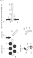
FIG. 1(a) illustrates a processed product (hereinafter, to be referred to as "wire processed product") 100A of a roundmetallic wire 100 processed using a round metallic wire processing apparatus 1 (refer toFIG. 3 ) The wire processedproduct 100A is used as, for example, a power line of a motor or the like as indicated inPatent Documents portions bent portions straight portions product 100A, in a range of thestraight portion 103 in the vicinity of the middle of the entire length, a cross-sectionnon-circular portion 105 having a non-circular cross-sectional shape in a diameter direction (a direction orthogonal to a longitudinal direction (axial center direction) of the round metallic wire 100) of the roundmetallic wire 100 is formed. A shape of the cross-sectionnon-circular portion 105 is formed in a rectangle having fourflat surfaces 105a to 105d on an outer peripheral surface as illustrated inFIG. 1(b) . Note that this shape of the cross-sectionnon-circular portion 105 will be further described later. - The wire processed
product 100A is set in a metal mold, and aresin member 200 is integrated by insert molding (refer toFIG. 2(a) ). At this time, as illustrated inFIG. 2(b) , theresin member 200 is integrated closely around the cross-sectionnon-circular portion 105. The cross-sectionnon-circular portion 105 has the fourflat surfaces 105a to 105d, which eliminates the occurrence of relative rotation between them and theresin member 200 closely covering their peripheries. As a result, the wire processedproduct 100A of the roundmetallic wire 100 gets rid of being rotated and displaced in an axial direction at the time of fastening with the terminal of the motor or the like or by action of external vibrations, or the like. Note that as indicated inPatent Documents products 100A of the roundmetallic wires 100 are subjected to insert molding together and covered with thecommon resin member 200 to thereby prevent a mutual displacement. - Next, a processing method and a processing apparatus for the round
metallic wire 100 used as described above will be described.FIG. 3 schematically illustrates a schematic configuration of the round metallicwire processing apparatus 1, andFIG. 4 andFIG. 5 each schematically illustrate each of processing machines for each processing step. As illustrated in these figures, the round metallicwire processing apparatus 1 includes a straighteningmachine 10, a cross-section non-circularportion forming machine 20, abending machine 30, and acutting machine 40. - The straightening
machine 10 includes, for example, a plurality of straighteningrollers 11 disposed to be opposed, as illustrated inFIG. 4 andFIG. 5 . The roundmetallic wire 100 targeted for processing is formed of a cross-section circular solid wire having a surface covered with enamel and made of metal such as copper, and provided as a coiled material wound in a coil shape. The straighteningmachine 10 is provided to correct its winding tendency caused by being wound in a coil shape. Here, in the wire processedproduct 100A illustrated inFIG. 1 , end portions serve as the connectingportions portions - A cross-section non-circular
portion forming machine 20 forms a predetermined portion of the roundmetallic wire 100 processed linearly by the straighteningmachine 10 in a non-circular shape in the cross-sectional shape in the diameter direction of the roundmetallic wire 100. A concrete structure of the cross-section non-circularportion forming machine 20 is not limited, but for example, is constituted of a pressing machine havingpressing portions 21 which sandwiches the roundmetallic wire 100 on both sides along the diameter direction as illustrated inFIG. 4 andFIG. 5 . A facingsurface 21a facing the roundmetallic wire 100 on thepressing portion 21 has a shape roughly fitted to anabutting surface 31a of awire holding portion 31 of the bendingmachine 30 which separates from and approaches the round metallic wire 100 (refer toFIG. 6(a), (b) ). Concretely, for example, thewire holding portion 31 has at least the two abuttingsurfaces 31a on the roundmetallic wire 100, and at least one surface of them is formed of a flat surface, and hence at least one of thepressing surfaces 21a of thepressing portions 21 is also formed in a flat surface. - In this example, both the facing
surfaces pressing portions portion forming machine 20 are formed as the flat surfaces. Accordingly, when thesepressing portions flat surfaces non-circular portion 105 are formed, and next, by turning the roundmetallic wire 100 by 90 degrees centered at an axial center and making thepressing portions flat surfaces non-circular portion 105 having a substantially rectangular cross section in the diameter direction is formed. - However, the cross-sectional shape of the cross-section
non-circular portion 105 is applicable unless circular, and for example, the flat surface may be formed only on one surface, or the flat surfaces may be formed only on two opposing surfaces. They may be formed on three or five surfaces or more. However, the closer the cross-sectional shape is to a circle, the more likely relative rotation between the cross-sectionnon-circular portion 105 and thewire holding portion 31 of the bending machine 230 and the relative rotation, when theresin member 200 illustrated inFIG. 2 is molded integrally, between the two are to occur, and hence the flat surfaces are preferably set to eight surfaces or less. In addition to this, a modified cross section partially having any depression or projection such as a cross-section square or triangle is also applicable. In any case, these surfaces may each be in a shape having at least one flat surface capable of surface contact with theabutting surface 31a of thewire holding portion 31 of the bendingmachine 30. Having at least one flat surface causes theabutting surface 31a of thewire holding portion 31 of the bendingmachine 30 to come into surface contact therewith, and thereby the roundmetallic wire 100 can be prevented from rotating centered at the axial center at the time of bending. - As the bending
machine 30, for example, the one provided with the wire holding portion (chuck) 31 at a tip of a three-dimensionallymovable robot arm 32 as illustrated inFIG. 6(a) , the one having thewire holding portion 31 provided with a pair of opposing plates capable of separating from and approaching each other (corresponding to a portion in which work in a press die is held) as illustrated inFIG. 6(b) , or the like can be used. In each of thesewire holding portions 31, at least one surface (the two opposing surfaces in this embodiment) on which the roundmetallic wire 100 is held is set as the flat surface. Accordingly, as long as the roundmetallic wire 100 on which theflat surfaces 105a to 105d are formed by the cross-section non-circularportion forming machine 20 is set in each of thesewire holding portions 31, the roundmetallic wire 100 does not rotate centered at the axial center despite having a cross-section circular shape in portions expect the cross-sectionnon-circular portion 105. - In
FIG. 6(a) , the bendingmachine 30 has the wire holding portion (chuck) 31 and a working portion (not illustrated) which comes into contact with the roundmetallic wire 100, and either or both of these move three-dimensionally, and thereby the roundmetallic wire 100 is bent at a predetermined angle in a predetermined direction, or the like, and the roundmetallic wire 100 is processed in a predetermined three-dimensional shape to design specifications. InFIG. 6(b) , for example, the roundmetallic wire 100 is held between a pair of the abuttingsurfaces wire holding portion 31 formed of the two plates, and a portion protruding from thewire holding portion 31 is approached from any direction by and brought into contact with a processing tool 33 (refer to "bending step" inFIG. 4 andFIG. 5 ) to be thereby processed in a predetermined shape. Then, by varying the directions of the roundmetallic wire 100 or using the one capable of approaching it from different directions as the processing tool, the three-dimensional shape is imparted. Note that a concrete structure of the bendingmachine 30 is not limited at all as long as the roundmetallic wire 100 can be subjected to bending. - The cutting
machine 40 cuts the roundmetallic wire 100 in a predetermined length in accordance with the design specifications. As long as the roundmetallic wire 100 can be cut, its structure is not limited at all. In this example, a cuttingmachine control unit 50 which automatically operates the cuttingmachine 40 is included (refer toFIG. 3 ). The cuttingmachine control unit 50 controls the cuttingmachine 40 so as to perform cutting operation in the predetermined length in accordance with the beforehand set design specifications. The cuttingmachine control unit 50 only needs to control a cutting length, and moreover, timing of operating the cuttingmachine 40 can also be automatically controlled. Specifically, the roundmetallic wire 100 is straightened by the above-describedstraightening machine 10, and thereafter at either timing before being transferred to the cross-section non-circular portion forming machine 20 (the state inFIG. 4 ) or timing before being transferred to the bendingmachine 30 after the formation of the cross-section non-circular portion 105 (the state inFIG. 5 ), the cuttingmachine 40 is operated to cut the roundmetallic wire 100 in the predetermined length. - The timing of cutting by using the cutting
machine 40 can be optionally set depending on the kind of the three-dimensional shape to be imparted to the roundmetallic wire 100, the required dimensional accuracy, and the like. As illustrated inFIG. 4 , cutting after the straightening makes, even when the cross-sectionnon-circular portion 105 is formed in any position of end portions and a middle portion, its positioning easy, and also makes handling of the bending thereafter easy. Further, cutting after the bending sometimes also causes deformation due to a shock at the time of cutting, but the prior cutting eliminates such a possibility as described above. - As illustrated in
FIG. 5 , cutting before the bending after the formation of the cross-sectionnon-circular portion 105 makes it easy to perform the bending, but makes the positioning of the formation position of the cross-sectionnon-circular portion 105 more difficult than that in cutting prior thereto since the cross-sectionnon-circular portion 105 is formed while keeping the roundmetallic wire 100 long. On one hand, by forming the cross-sectionnon-circular portion 105, a size in a long direction is sometimes somewhat affected by a deformation in the diameter direction. Further, the cutting after the bending sometimes causes the deformation as described above. Thus, when the dimensional accuracy is required more strictly, or the like, the roundmetallic wire 100 is also considered to be kept long until the formation of the cross-sectionnon-circular portion 105 and cut before the bending. - Next, one example of a method for processing the round
metallic wire 100 will be described based onFIG. 4 andFIG. 7 . In the processing method, as described above, the material provided in a coil shape is transferred to the straighteningmachine 10 of the round metallicwire processing apparatus 1 to be linearly corrected (S1 inFIG. 7 ). Thereafter, in accordance with specifications of the wire processedproduct 100A, an enamel cover is peeled for each predetermined distance so that the connecting ends 101, 101 to the terminals or the like at attachment positions are formed. - Next, for example, the linearly corrected round
metallic wire 100 is cut in a predetermined length by the cutting machine 40 (S2 inFIG. 7 ). The advantage such that cutting at this time makes handling of later processing easy is as described above. Subsequently, the roundmetallic wire 100 cut in the predetermined length is transferred to the cross-section non-circularportion forming machine 20 to form the cross-section non-circular portion 105 (S3 inFIG. 7 ). The cross-sectionnon-circular portion 105 is formed in at least one position. The cross-sectionnon-circular portion 105 is provided to prevent movement in a rotation direction when held by thewire holding portion 31 in the bendingmachine 30, and in varying the portion held by thewire holding portion 31, using a plurality of thebending machines 30, or the like, corresponding thereto, the cross-sectionnon-circular portions 105 can be formed in a plurality of positions. - Next, the cross-section
non-circular portion 105 is held by thewire holding portion 31 of the bendingmachine 30, and a three-dimensional shape in accordance with the design specifications is imparted (S4 inFIG. 7 ). At this time, when the plurality of bendingmachines 30 are used, it is possible to in theinitial bending machine 30, hold the cross-sectionnon-circular portion 105 in a certain predetermined position in thewire holding portion 31 and perform the bending, and thereafter in thenext bending machine 30, hold the cross-sectionnon-circular portion 105 formed in a different position therefrom in thewire holding portion 31 and perform the bending, for example. - This completes the wire processed
product 100A. Note that the timing of the cutting step is thus not limited to before the formation of the cross-section non-circular portion after the correction, but as illustrated inFIG. 5 , is also applicable to after the formation of the cross-section non-circular portion as described above.FIG. 8 is a flowchart illustrating one example of processing steps in that case, and after the correction step (S5 inFIG. 8 ), the cross-section non-circular portion is formed (S6 inFIG. 8 ), cutting is thereafter performed (S7 inFIG. 8 ), and the bending step is performed (S8 inFIG. 8 ) to obtain the wire processedproduct 100A. - According to this example, with respect to the round
metallic wire 100, the cross-sectionnon-circular portion 105 is formed before the bending. Therefore, by holding the cross-sectionnon-circular portion 105 in thewire holding portion 31, the bending can be performed, which allows the prevention of the movement in the rotation direction centered at the axial center at the time of bending, or the like, resulting in enabling an increase of bending accuracy. Further, making a holding position of thewire holding portion 31 stable reduces variations in processing accuracy among products. Further, the roundmetallic wire 100 is transferred between the machines by feed rollers (not illustrated), and after the formation of the cross-sectionnon-circular portion 105, a slide with respect to the feed rollers is suppressed, which also enables suppression of a deterioration of the processing accuracy caused by variations in feed rate. - Further, when dimensions of the processed wire processed
product 100A are measured using an optical microscope, a visible outline of the cross-sectionnon-circular portion 105, in particular, a surface processed in the flat surface is easy to observe. That is, in a circular cross section, it is difficult to focus on a tangent of the circular cross section when it is observed by the optical microscope, which sometimes affects dimensional measurement accuracy, but according to this example, it becomes easy to focus on the visible outline of the flat surface or the like, which increases the dimensional measurement accuracy. - Next, the wire processed
product 100A of this example is used as a power distribution component, wherein it is integrated with theresin member 200 which functions as a rotation stopper for an attachment portion, or the like, theresin member 200 is integrated with the cross-sectionnon-circular portion 105 by the insert molding (S10) to obtain a power distribution component 300 (refer toFIG. 2 ), as illustrated inFIG. 9 . The obtainedpower distribution component 300 does not rotate mutually since theresin member 200 is integrated with the cross-sectionnon-circular portion 105. According to the present invention, the cross-section non-circular portion is not required to be formed by additional processing after completing the wire processed product as conventionally formed, and it is possible to prevent an influence on dimensional accuracy and a deformation accompanying the additional processing. - According to the above, the
power distribution component 300 including the wire processedproduct 100A obtained by the present invention is particularly suitable for uses requiring high dimensional accuracy, accuracy of form, and the like despite an inexpensive round wire as compared with a square wire. -
- 1 round metallic wire processing apparatus
- 10 strengthening machine
- 11 strengthening roller
- 20 cross-section non-circular portion forming machine
- 21 pressing portion
- 21a facing surface
- 30 bending machine
- 31 wire holding portion
- 31a abutting surface
- 40 cutting machine
- 50 cutting machine control unit
- 100 round metallic wire
- 100A wire processed product (finished processed product of round metallic wire)
- 105 cross-section non-circular portion
- 105a, 105b, 105c, 105d flat surface
- 200 resin member
- 300 power distribution component
Claims (3)
- A method for manufacturing a power distribution component (300) for use in a predetermined position of an electric device, the method including steps of processing a round metallic wire (100) formed of a cross-section circular solid wire, for use as a conductor of the power distribution component (300), the method comprising:a correction step of linearly correcting a coiled material of the round metallic wire (100);a cross-section non-circular portion forming step of forming a cross-section non-circular portion (105) having a non-circular cross-sectional shape in a diameter direction in at least one position of the round metallic wire (100) linearly corrected by the correction step;a bending step of holding the cross-section non-circular portion (105) in a wire holding portion (31) of a bending machine (30) and performing bending in a predetermined three-dimensional shape; andthe step of integrally attaching a resin member (200) on an outer periphery of the cross-section non-circular portion (105) of the processed product of the round metallic wire (100).
- The method for manufacturing a power distribution component (300) according to claim 1, wherein in the cross-section non-circular portion forming step, the cross-section non-circular portion (105) is processed in a shape including a flat surface (105a,b,c,d) which comes into surface contact with an abutting surface (31a) of the wire holding portion (31) of the bending machine (30).
- The method for manufacturing a power distribution component (300) according to claim 1 or 2, wherein at either timing after the correction step and before the cross-section non-circular portion forming step or timing after the cross-section non-circular portion forming step, the round metallic wire is cut in a predetermined length.
Applications Claiming Priority (2)
| Application Number | Priority Date | Filing Date | Title |
|---|---|---|---|
| JP2019193979A JP7141673B2 (en) | 2019-10-25 | 2019-10-25 | METHOD FOR PROCESSING ROUND METAL WIRE, MACHINE FOR ROUND METAL WIRE, AND METHOD FOR MANUFACTURING POWER DISTRIBUTION PARTS |
| PCT/JP2020/036121 WO2021079681A1 (en) | 2019-10-25 | 2020-09-24 | Method for processing round metallic wire rod, apparatus for processing round metallic wire rod, and production method for power distribution component |
Publications (4)
| Publication Number | Publication Date |
|---|---|
| EP4050623A1 EP4050623A1 (en) | 2022-08-31 |
| EP4050623A4 EP4050623A4 (en) | 2022-12-21 |
| EP4050623B1 true EP4050623B1 (en) | 2024-09-04 |
| EP4050623C0 EP4050623C0 (en) | 2024-09-04 |
Family
ID=75619308
Family Applications (1)
| Application Number | Title | Priority Date | Filing Date |
|---|---|---|---|
| EP20879857.9A Active EP4050623B1 (en) | 2019-10-25 | 2020-09-24 | Production method for power distribution component |
Country Status (5)
| Country | Link |
|---|---|
| US (1) | US11858029B2 (en) |
| EP (1) | EP4050623B1 (en) |
| JP (1) | JP7141673B2 (en) |
| CN (1) | CN113939374B (en) |
| WO (1) | WO2021079681A1 (en) |
Family Cites Families (15)
| Publication number | Priority date | Publication date | Assignee | Title |
|---|---|---|---|---|
| US1709938A (en) * | 1927-12-31 | 1929-04-23 | Hump Hairpin Mfg Co | Method and machine for producing hair-gripping fasteners |
| US1936611A (en) * | 1931-04-24 | 1933-11-28 | American Can Co | Manufacture of container opening keys |
| US2838075A (en) * | 1953-10-30 | 1958-06-10 | Sylvania Electric Prod | Wire flattening, hooking, and feeding device |
| US4654912A (en) * | 1984-09-18 | 1987-04-07 | Gray John C | Production of threaded metal rods for making U-bolts |
| JPS62137132A (en) * | 1985-12-11 | 1987-06-20 | Toshiba Corp | Working method for wire |
| US5203191A (en) * | 1990-05-02 | 1993-04-20 | North America Omcg, Inc. | Versatile automatic metal strip working machine |
| BE1009938A6 (en) * | 1996-01-31 | 1997-11-04 | Piminvest N V | Method for application of characters in an object. |
| JP2003045231A (en) | 2001-07-30 | 2003-02-14 | Yaskawa Electric Corp | Busbar for controller |
| US7571631B2 (en) * | 2005-09-20 | 2009-08-11 | 01 Inc. | Method of manufacturing a woodworker's holdfast |
| JP2014128095A (en) | 2012-12-26 | 2014-07-07 | Toyota Motor Corp | Power line fixing member |
| JP2014161872A (en) | 2013-02-25 | 2014-09-08 | Saijo Inx Co Ltd | Processing method of bus bar material |
| RU2707847C1 (en) * | 2014-09-18 | 2019-11-29 | Ниппон Стил Корпорейшн | Method of making molded article, tooling and tubular article |
| JP2016221551A (en) | 2015-06-01 | 2016-12-28 | 株式会社フジックス | Device and method for manufacturing rod-like bus bar |
| JP2017055486A (en) | 2015-09-07 | 2017-03-16 | トヨタ自動車株式会社 | Power line coupling structure of rotating electric machine stator |
| KR101748862B1 (en) * | 2015-12-28 | 2017-06-19 | 정의선 | Built-in antenna manufacturing method for a mobile phone |
-
2019
- 2019-10-25 JP JP2019193979A patent/JP7141673B2/en active Active
-
2020
- 2020-09-24 CN CN202080042554.1A patent/CN113939374B/en active Active
- 2020-09-24 WO PCT/JP2020/036121 patent/WO2021079681A1/en not_active Ceased
- 2020-09-24 US US17/761,749 patent/US11858029B2/en active Active
- 2020-09-24 EP EP20879857.9A patent/EP4050623B1/en active Active
Also Published As
| Publication number | Publication date |
|---|---|
| EP4050623A1 (en) | 2022-08-31 |
| US11858029B2 (en) | 2024-01-02 |
| EP4050623A4 (en) | 2022-12-21 |
| CN113939374B (en) | 2025-08-08 |
| CN113939374A (en) | 2022-01-14 |
| JP7141673B2 (en) | 2022-09-26 |
| WO2021079681A1 (en) | 2021-04-29 |
| JP2021068626A (en) | 2021-04-30 |
| EP4050623C0 (en) | 2024-09-04 |
| US20220371075A1 (en) | 2022-11-24 |
Similar Documents
| Publication | Publication Date | Title |
|---|---|---|
| EP3048709B1 (en) | Coil-end-molding device and method | |
| KR101541663B1 (en) | Segmented-coil manufacturing method, segmented-coil manufacturing device, and segmented coil manufactured using segmented-coil manufacturing device | |
| US20210296044A1 (en) | Common-mode choke coil and method of manufacturing common-mode choke coil | |
| JP5681250B1 (en) | Conductor piece set molding method and conductor piece set molding apparatus | |
| JP6166046B2 (en) | Segment manufacturing method and segment manufacturing apparatus | |
| JP5785117B2 (en) | Winding device and winding method | |
| JP2003143818A (en) | Manufacturing method of split conductor of coil | |
| US20260121494A1 (en) | Method of manufacturing armature | |
| US11858029B2 (en) | Method for processing round metallic wire, round metallic wire processing apparatus and method for manufacturing power distribution component | |
| US20190312494A1 (en) | Method and apparatus for producing rotating electric machine stator | |
| JP5674693B2 (en) | Winding forming apparatus and winding forming method | |
| WO2007105451A1 (en) | Metal terminal, coil component and method for holding and fixing conductive wire | |
| CN108011477A (en) | The manufacture method and motor of stator | |
| JP5436397B2 (en) | Winding end forming apparatus and method | |
| US20160276910A1 (en) | Method of manufacturing assembled conductor and electric motor | |
| JP2019103251A (en) | Conductor wire forming apparatus and method | |
| JP7151645B2 (en) | Conductor wire forming apparatus and method for producing formed conductor | |
| CN109720934B (en) | Winding end binding device | |
| JP2006224111A (en) | Long object folding method, long object folding mold and long object folding apparatus | |
| CN113145704A (en) | Bent pipe manufacturing device and bent pipe manufacturing method | |
| US11583916B2 (en) | Apparatus for straightening wire ends | |
| US20250239925A1 (en) | Method of manufacturing armature | |
| JP2003009478A (en) | Coil twist shaping method | |
| JPS5944869B2 (en) | Manufacturing method of flat wire wheels for electric motors |
Legal Events
| Date | Code | Title | Description |
|---|---|---|---|
| STAA | Information on the status of an ep patent application or granted ep patent |
Free format text: STATUS: THE INTERNATIONAL PUBLICATION HAS BEEN MADE |
|
| PUAI | Public reference made under article 153(3) epc to a published international application that has entered the european phase |
Free format text: ORIGINAL CODE: 0009012 |
|
| STAA | Information on the status of an ep patent application or granted ep patent |
Free format text: STATUS: REQUEST FOR EXAMINATION WAS MADE |
|
| 17P | Request for examination filed |
Effective date: 20220318 |
|
| AK | Designated contracting states |
Kind code of ref document: A1 Designated state(s): AL AT BE BG CH CY CZ DE DK EE ES FI FR GB GR HR HU IE IS IT LI LT LU LV MC MK MT NL NO PL PT RO RS SE SI SK SM TR |
|
| A4 | Supplementary search report drawn up and despatched |
Effective date: 20221122 |
|
| DAV | Request for validation of the european patent (deleted) | ||
| DAX | Request for extension of the european patent (deleted) | ||
| RIC1 | Information provided on ipc code assigned before grant |
Ipc: H01B 7/18 20060101ALI20221116BHEP Ipc: H02K 15/04 20060101ALI20221116BHEP Ipc: B21F 5/00 20060101ALI20221116BHEP Ipc: B21F 1/02 20060101ALI20221116BHEP Ipc: B21F 1/00 20060101ALI20221116BHEP Ipc: B21D 53/00 20060101ALI20221116BHEP Ipc: B21D 11/02 20060101ALI20221116BHEP Ipc: H01B 13/00 20060101AFI20221116BHEP |
|
| RIN1 | Information on inventor provided before grant (corrected) |
Inventor name: TODA, MAMORU Inventor name: TAKEUCHI, KUNIHITO Inventor name: SEKITOMI, YUJI |
|
| STAA | Information on the status of an ep patent application or granted ep patent |
Free format text: STATUS: EXAMINATION IS IN PROGRESS |
|
| 17Q | First examination report despatched |
Effective date: 20231024 |
|
| GRAP | Despatch of communication of intention to grant a patent |
Free format text: ORIGINAL CODE: EPIDOSNIGR1 |
|
| STAA | Information on the status of an ep patent application or granted ep patent |
Free format text: STATUS: GRANT OF PATENT IS INTENDED |
|
| INTG | Intention to grant announced |
Effective date: 20240503 |
|
| GRAS | Grant fee paid |
Free format text: ORIGINAL CODE: EPIDOSNIGR3 |
|
| GRAA | (expected) grant |
Free format text: ORIGINAL CODE: 0009210 |
|
| STAA | Information on the status of an ep patent application or granted ep patent |
Free format text: STATUS: THE PATENT HAS BEEN GRANTED |
|
| AK | Designated contracting states |
Kind code of ref document: B1 Designated state(s): AL AT BE BG CH CY CZ DE DK EE ES FI FR GB GR HR HU IE IS IT LI LT LU LV MC MK MT NL NO PL PT RO RS SE SI SK SM TR |
|
| REG | Reference to a national code |
Ref country code: GB Ref legal event code: FG4D |
|
| REG | Reference to a national code |
Ref country code: CH Ref legal event code: EP |
|
| REG | Reference to a national code |
Ref country code: IE Ref legal event code: FG4D |
|
| REG | Reference to a national code |
Ref country code: DE Ref legal event code: R096 Ref document number: 602020037310 Country of ref document: DE |
|
| U01 | Request for unitary effect filed |
Effective date: 20240905 |
|
| U07 | Unitary effect registered |
Designated state(s): AT BE BG DE DK EE FI FR IT LT LU LV MT NL PT RO SE SI Effective date: 20240923 |
|
| U20 | Renewal fee for the european patent with unitary effect paid |
Year of fee payment: 5 Effective date: 20240926 |
|
| PG25 | Lapsed in a contracting state [announced via postgrant information from national office to epo] |
Ref country code: NO Free format text: LAPSE BECAUSE OF FAILURE TO SUBMIT A TRANSLATION OF THE DESCRIPTION OR TO PAY THE FEE WITHIN THE PRESCRIBED TIME-LIMIT Effective date: 20241204 |
|
| PG25 | Lapsed in a contracting state [announced via postgrant information from national office to epo] |
Ref country code: GR Free format text: LAPSE BECAUSE OF FAILURE TO SUBMIT A TRANSLATION OF THE DESCRIPTION OR TO PAY THE FEE WITHIN THE PRESCRIBED TIME-LIMIT Effective date: 20241205 Ref country code: PL Free format text: LAPSE BECAUSE OF FAILURE TO SUBMIT A TRANSLATION OF THE DESCRIPTION OR TO PAY THE FEE WITHIN THE PRESCRIBED TIME-LIMIT Effective date: 20240904 |
|
| PG25 | Lapsed in a contracting state [announced via postgrant information from national office to epo] |
Ref country code: HR Free format text: LAPSE BECAUSE OF FAILURE TO SUBMIT A TRANSLATION OF THE DESCRIPTION OR TO PAY THE FEE WITHIN THE PRESCRIBED TIME-LIMIT Effective date: 20240904 |
|
| PG25 | Lapsed in a contracting state [announced via postgrant information from national office to epo] |
Ref country code: ES Free format text: LAPSE BECAUSE OF FAILURE TO SUBMIT A TRANSLATION OF THE DESCRIPTION OR TO PAY THE FEE WITHIN THE PRESCRIBED TIME-LIMIT Effective date: 20240904 Ref country code: RS Free format text: LAPSE BECAUSE OF FAILURE TO SUBMIT A TRANSLATION OF THE DESCRIPTION OR TO PAY THE FEE WITHIN THE PRESCRIBED TIME-LIMIT Effective date: 20241204 |
|
| PG25 | Lapsed in a contracting state [announced via postgrant information from national office to epo] |
Ref country code: RS Free format text: LAPSE BECAUSE OF FAILURE TO SUBMIT A TRANSLATION OF THE DESCRIPTION OR TO PAY THE FEE WITHIN THE PRESCRIBED TIME-LIMIT Effective date: 20241204 Ref country code: PL Free format text: LAPSE BECAUSE OF FAILURE TO SUBMIT A TRANSLATION OF THE DESCRIPTION OR TO PAY THE FEE WITHIN THE PRESCRIBED TIME-LIMIT Effective date: 20240904 Ref country code: NO Free format text: LAPSE BECAUSE OF FAILURE TO SUBMIT A TRANSLATION OF THE DESCRIPTION OR TO PAY THE FEE WITHIN THE PRESCRIBED TIME-LIMIT Effective date: 20241204 Ref country code: HR Free format text: LAPSE BECAUSE OF FAILURE TO SUBMIT A TRANSLATION OF THE DESCRIPTION OR TO PAY THE FEE WITHIN THE PRESCRIBED TIME-LIMIT Effective date: 20240904 Ref country code: GR Free format text: LAPSE BECAUSE OF FAILURE TO SUBMIT A TRANSLATION OF THE DESCRIPTION OR TO PAY THE FEE WITHIN THE PRESCRIBED TIME-LIMIT Effective date: 20241205 Ref country code: ES Free format text: LAPSE BECAUSE OF FAILURE TO SUBMIT A TRANSLATION OF THE DESCRIPTION OR TO PAY THE FEE WITHIN THE PRESCRIBED TIME-LIMIT Effective date: 20240904 |
|
| PG25 | Lapsed in a contracting state [announced via postgrant information from national office to epo] |
Ref country code: IS Free format text: LAPSE BECAUSE OF FAILURE TO SUBMIT A TRANSLATION OF THE DESCRIPTION OR TO PAY THE FEE WITHIN THE PRESCRIBED TIME-LIMIT Effective date: 20250104 |
|
| PG25 | Lapsed in a contracting state [announced via postgrant information from national office to epo] |
Ref country code: SM Free format text: LAPSE BECAUSE OF FAILURE TO SUBMIT A TRANSLATION OF THE DESCRIPTION OR TO PAY THE FEE WITHIN THE PRESCRIBED TIME-LIMIT Effective date: 20240904 |
|
| PG25 | Lapsed in a contracting state [announced via postgrant information from national office to epo] |
Ref country code: CZ Free format text: LAPSE BECAUSE OF FAILURE TO SUBMIT A TRANSLATION OF THE DESCRIPTION OR TO PAY THE FEE WITHIN THE PRESCRIBED TIME-LIMIT Effective date: 20240904 |
|
| PG25 | Lapsed in a contracting state [announced via postgrant information from national office to epo] |
Ref country code: SK Free format text: LAPSE BECAUSE OF FAILURE TO SUBMIT A TRANSLATION OF THE DESCRIPTION OR TO PAY THE FEE WITHIN THE PRESCRIBED TIME-LIMIT Effective date: 20240904 |
|
| REG | Reference to a national code |
Ref country code: CH Ref legal event code: PL |
|
| PG25 | Lapsed in a contracting state [announced via postgrant information from national office to epo] |
Ref country code: MC Free format text: LAPSE BECAUSE OF FAILURE TO SUBMIT A TRANSLATION OF THE DESCRIPTION OR TO PAY THE FEE WITHIN THE PRESCRIBED TIME-LIMIT Effective date: 20240904 |
|
| PLBE | No opposition filed within time limit |
Free format text: ORIGINAL CODE: 0009261 |
|
| STAA | Information on the status of an ep patent application or granted ep patent |
Free format text: STATUS: NO OPPOSITION FILED WITHIN TIME LIMIT |
|
| PG25 | Lapsed in a contracting state [announced via postgrant information from national office to epo] |
Ref country code: CH Free format text: LAPSE BECAUSE OF NON-PAYMENT OF DUE FEES Effective date: 20240930 |
|
| PG25 | Lapsed in a contracting state [announced via postgrant information from national office to epo] |
Ref country code: IE Free format text: LAPSE BECAUSE OF NON-PAYMENT OF DUE FEES Effective date: 20240924 |
|
| 26N | No opposition filed |
Effective date: 20250605 |
|
| GBPC | Gb: european patent ceased through non-payment of renewal fee |
Effective date: 20241204 |
|
| PG25 | Lapsed in a contracting state [announced via postgrant information from national office to epo] |
Ref country code: GB Free format text: LAPSE BECAUSE OF NON-PAYMENT OF DUE FEES Effective date: 20241204 |
|
| U20 | Renewal fee for the european patent with unitary effect paid |
Year of fee payment: 6 Effective date: 20250926 |
|
| PG25 | Lapsed in a contracting state [announced via postgrant information from national office to epo] |
Ref country code: CY Free format text: LAPSE BECAUSE OF FAILURE TO SUBMIT A TRANSLATION OF THE DESCRIPTION OR TO PAY THE FEE WITHIN THE PRESCRIBED TIME-LIMIT; INVALID AB INITIO Effective date: 20200924 |
|
| PG25 | Lapsed in a contracting state [announced via postgrant information from national office to epo] |
Ref country code: HU Free format text: LAPSE BECAUSE OF FAILURE TO SUBMIT A TRANSLATION OF THE DESCRIPTION OR TO PAY THE FEE WITHIN THE PRESCRIBED TIME-LIMIT; INVALID AB INITIO Effective date: 20200924 |