EP4050620A1 - Universal load beam features that characterize patient motion in three dimensions in a hospital bed - Google Patents
Universal load beam features that characterize patient motion in three dimensions in a hospital bed Download PDFInfo
- Publication number
- EP4050620A1 EP4050620A1 EP22158232.3A EP22158232A EP4050620A1 EP 4050620 A1 EP4050620 A1 EP 4050620A1 EP 22158232 A EP22158232 A EP 22158232A EP 4050620 A1 EP4050620 A1 EP 4050620A1
- Authority
- EP
- European Patent Office
- Prior art keywords
- patient
- motion
- support apparatus
- load cells
- movement
- Prior art date
- Legal status (The legal status is an assumption and is not a legal conclusion. Google has not performed a legal analysis and makes no representation as to the accuracy of the status listed.)
- Pending
Links
Images



Classifications
-
- G—PHYSICS
- G16—INFORMATION AND COMMUNICATION TECHNOLOGY [ICT] SPECIALLY ADAPTED FOR SPECIFIC APPLICATION FIELDS
- G16H—HEALTHCARE INFORMATICS, i.e. INFORMATION AND COMMUNICATION TECHNOLOGY [ICT] SPECIALLY ADAPTED FOR THE HANDLING OR PROCESSING OF MEDICAL OR HEALTHCARE DATA
- G16H40/00—ICT specially adapted for the management or administration of healthcare resources or facilities; ICT specially adapted for the management or operation of medical equipment or devices
- G16H40/60—ICT specially adapted for the management or administration of healthcare resources or facilities; ICT specially adapted for the management or operation of medical equipment or devices for the operation of medical equipment or devices
- G16H40/63—ICT specially adapted for the management or administration of healthcare resources or facilities; ICT specially adapted for the management or operation of medical equipment or devices for the operation of medical equipment or devices for local operation
-
- A—HUMAN NECESSITIES
- A61—MEDICAL OR VETERINARY SCIENCE; HYGIENE
- A61G—TRANSPORT, PERSONAL CONVEYANCES, OR ACCOMMODATION SPECIALLY ADAPTED FOR PATIENTS OR DISABLED PERSONS; OPERATING TABLES OR CHAIRS; CHAIRS FOR DENTISTRY; FUNERAL DEVICES
- A61G7/00—Beds specially adapted for nursing; Devices for lifting patients or disabled persons
- A61G7/05—Parts, details or accessories of beds
- A61G7/0527—Weighing devices
-
- A—HUMAN NECESSITIES
- A61—MEDICAL OR VETERINARY SCIENCE; HYGIENE
- A61B—DIAGNOSIS; SURGERY; IDENTIFICATION
- A61B5/00—Measuring for diagnostic purposes; Identification of persons
- A61B5/0002—Remote monitoring of patients using telemetry, e.g. transmission of vital signals via a communication network
- A61B5/0015—Remote monitoring of patients using telemetry, e.g. transmission of vital signals via a communication network characterised by features of the telemetry system
- A61B5/002—Monitoring the patient using a local or closed circuit, e.g. in a room or building
-
- A—HUMAN NECESSITIES
- A61—MEDICAL OR VETERINARY SCIENCE; HYGIENE
- A61B—DIAGNOSIS; SURGERY; IDENTIFICATION
- A61B5/00—Measuring for diagnostic purposes; Identification of persons
- A61B5/103—Measuring devices for testing the shape, pattern, colour, size or movement of the body or parts thereof, for diagnostic purposes
- A61B5/1036—Measuring load distribution, e.g. podologic studies
-
- A—HUMAN NECESSITIES
- A61—MEDICAL OR VETERINARY SCIENCE; HYGIENE
- A61B—DIAGNOSIS; SURGERY; IDENTIFICATION
- A61B5/00—Measuring for diagnostic purposes; Identification of persons
- A61B5/103—Measuring devices for testing the shape, pattern, colour, size or movement of the body or parts thereof, for diagnostic purposes
- A61B5/1036—Measuring load distribution, e.g. podologic studies
- A61B5/1038—Measuring plantar pressure during gait
-
- A—HUMAN NECESSITIES
- A61—MEDICAL OR VETERINARY SCIENCE; HYGIENE
- A61B—DIAGNOSIS; SURGERY; IDENTIFICATION
- A61B5/00—Measuring for diagnostic purposes; Identification of persons
- A61B5/103—Measuring devices for testing the shape, pattern, colour, size or movement of the body or parts thereof, for diagnostic purposes
- A61B5/11—Measuring movement of the entire body or parts thereof, e.g. head or hand tremor or mobility of a limb
- A61B5/1113—Local tracking of patients, e.g. in a hospital or private home
- A61B5/1115—Monitoring leaving of a patient support, e.g. a bed or a wheelchair
-
- A—HUMAN NECESSITIES
- A61—MEDICAL OR VETERINARY SCIENCE; HYGIENE
- A61B—DIAGNOSIS; SURGERY; IDENTIFICATION
- A61B5/00—Measuring for diagnostic purposes; Identification of persons
- A61B5/103—Measuring devices for testing the shape, pattern, colour, size or movement of the body or parts thereof, for diagnostic purposes
- A61B5/11—Measuring movement of the entire body or parts thereof, e.g. head or hand tremor or mobility of a limb
- A61B5/1116—Determining posture transitions
-
- A—HUMAN NECESSITIES
- A61—MEDICAL OR VETERINARY SCIENCE; HYGIENE
- A61B—DIAGNOSIS; SURGERY; IDENTIFICATION
- A61B5/00—Measuring for diagnostic purposes; Identification of persons
- A61B5/72—Signal processing specially adapted for physiological signals or for diagnostic purposes
- A61B5/7203—Signal processing specially adapted for physiological signals or for diagnostic purposes for noise prevention, reduction or removal
- A61B5/7207—Signal processing specially adapted for physiological signals or for diagnostic purposes for noise prevention, reduction or removal of noise induced by motion artifacts
- A61B5/721—Signal processing specially adapted for physiological signals or for diagnostic purposes for noise prevention, reduction or removal of noise induced by motion artifacts using a separate sensor to detect motion or using motion information derived from signals other than the physiological signal to be measured
-
- A—HUMAN NECESSITIES
- A61—MEDICAL OR VETERINARY SCIENCE; HYGIENE
- A61G—TRANSPORT, PERSONAL CONVEYANCES, OR ACCOMMODATION SPECIALLY ADAPTED FOR PATIENTS OR DISABLED PERSONS; OPERATING TABLES OR CHAIRS; CHAIRS FOR DENTISTRY; FUNERAL DEVICES
- A61G7/00—Beds specially adapted for nursing; Devices for lifting patients or disabled persons
- A61G7/002—Beds specially adapted for nursing; Devices for lifting patients or disabled persons having adjustable mattress frame
- A61G7/015—Beds specially adapted for nursing; Devices for lifting patients or disabled persons having adjustable mattress frame divided into different adjustable sections, e.g. for Gatch position
-
- A—HUMAN NECESSITIES
- A61—MEDICAL OR VETERINARY SCIENCE; HYGIENE
- A61G—TRANSPORT, PERSONAL CONVEYANCES, OR ACCOMMODATION SPECIALLY ADAPTED FOR PATIENTS OR DISABLED PERSONS; OPERATING TABLES OR CHAIRS; CHAIRS FOR DENTISTRY; FUNERAL DEVICES
- A61G7/00—Beds specially adapted for nursing; Devices for lifting patients or disabled persons
- A61G7/002—Beds specially adapted for nursing; Devices for lifting patients or disabled persons having adjustable mattress frame
- A61G7/018—Control or drive mechanisms
-
- G—PHYSICS
- G01—MEASURING; TESTING
- G01G—WEIGHING
- G01G19/00—Weighing apparatus or methods adapted for special purposes not provided for in the preceding groups
- G01G19/44—Weighing apparatus or methods adapted for special purposes not provided for in the preceding groups for weighing persons
- G01G19/445—Weighing apparatus or methods adapted for special purposes not provided for in the preceding groups for weighing persons in a horizontal position
-
- G—PHYSICS
- G16—INFORMATION AND COMMUNICATION TECHNOLOGY [ICT] SPECIALLY ADAPTED FOR SPECIFIC APPLICATION FIELDS
- G16H—HEALTHCARE INFORMATICS, i.e. INFORMATION AND COMMUNICATION TECHNOLOGY [ICT] SPECIALLY ADAPTED FOR THE HANDLING OR PROCESSING OF MEDICAL OR HEALTHCARE DATA
- G16H50/00—ICT specially adapted for medical diagnosis, medical simulation or medical data mining; ICT specially adapted for detecting, monitoring or modelling epidemics or pandemics
- G16H50/30—ICT specially adapted for medical diagnosis, medical simulation or medical data mining; ICT specially adapted for detecting, monitoring or modelling epidemics or pandemics for calculating health indices; for individual health risk assessment
-
- A—HUMAN NECESSITIES
- A61—MEDICAL OR VETERINARY SCIENCE; HYGIENE
- A61G—TRANSPORT, PERSONAL CONVEYANCES, OR ACCOMMODATION SPECIALLY ADAPTED FOR PATIENTS OR DISABLED PERSONS; OPERATING TABLES OR CHAIRS; CHAIRS FOR DENTISTRY; FUNERAL DEVICES
- A61G2203/00—General characteristics of devices
- A61G2203/30—General characteristics of devices characterised by sensor means
- A61G2203/32—General characteristics of devices characterised by sensor means for force
-
- A—HUMAN NECESSITIES
- A61—MEDICAL OR VETERINARY SCIENCE; HYGIENE
- A61G—TRANSPORT, PERSONAL CONVEYANCES, OR ACCOMMODATION SPECIALLY ADAPTED FOR PATIENTS OR DISABLED PERSONS; OPERATING TABLES OR CHAIRS; CHAIRS FOR DENTISTRY; FUNERAL DEVICES
- A61G2203/00—General characteristics of devices
- A61G2203/30—General characteristics of devices characterised by sensor means
- A61G2203/36—General characteristics of devices characterised by sensor means for motion
Definitions
- the present disclosure relates to the use of load cells of a scale system of a patient support apparatus for characterizing patient motion. More specifically, the present disclosure relates to using the load cells of the scale system to characterize patient motion in three dimensions.
- load cells in patient support apparatuses, such as hospital beds, for example, to measure patient weight is known. Over time, approaches to using the information from the load cells to detect patient movement and to issue an alert or notification when the patient moves beyond a particular threshold have been developed.
- the use of load cells to make these determinations and inferences based on the motion is limited by the potential for external influences, such as the addition of equipment to the frame supported on the scale. When this is done, the existing information regarding the position of the patient is compromised as the weight distribution is changed unexpectedly.
- Movement in this context means a change in position of the patient on the patient support apparatus, such as rolling over or moving toward an edge of a patient support apparatus to exit the patient support apparatus, for example.
- it is important to identify patient motion such as movement of limbs or oscillating motion that does not result in a change of position or movement of the patient relative to the patient support apparatus, but is still useful in predicting patient outcomes or potential future patient movements.
- the present disclosure includes one or more of the following features, alone or in any combination.
- a patient support apparatus comprise a first frame, a plurality of load cells positioned on the first frame, a second frame, and a control system.
- the second frame is supported on the load cells such that the load of the second frame is measured by the load cells, the second frame configured to support a patient supported on the patient support apparatus such that the load of the patient is transferred through the plurality of load cells.
- the control system includes a controller.
- the controller is operable to receive a separate signal from each of the plurality of load cells, process the signals to identify, based on transient changes in the forces measured by each of the plurality of load cells, motion of the patient that does not result in relative movement of the patient relative to the second frame.
- the motion of the patient is further processed to characterize the nature of the patient motion and, based on the characterization of the patient motion automatically update a patient profile in a patient record to reflect the characterization of the patient motion.
- the transient changes in the forces measured by the load cells are indicative of motion of a least a portion of the patient in a vertical direction.
- the controller is operable to calculate the work done by the patient in the vertical direction to characterize the patient motion.
- the controller is operable to calculate the work done by the patient and distinguish between motion that results in movement of the patient's mass to a different position on the patient support apparatus from motion that does not result in movement of the patient's mass to a different position on the patient support apparatus and updates the patient profile to reflect the net movement of the patient and the motion that does not result in movement of the patient's mass to a different position on the patient support apparatus.
- the controller is operable to calculate a speed of movement of the center of gravity of the patient in the plane that is orthogonal to the direction of gravity to determine the amount of work done by the patient moving in the plane that is orthogonal to the direction of gravity.
- the controller is operable to calculate the work done by a patient that does not result in movement in the plane that is orthogonal to the direction of gravity.
- the controller is operable to determine the work that is done to move the patient in the direction of gravity and the work that is done to move the patient in the plane that is orthogonal to the direction of gravity and updates the patient profile based on the total work done by the patient.
- the controller is operable to distinguish between patient motion and non-patient motion artifacts and disregards non-patient motion artifacts when updating the patient profile.
- the controller is operable to determine the existence of a non-patient motion artifact by closed system analysis that detects that an additional load has been added to the load cells.
- the additional load is determined using an analysis of the sum of the values detected by the load cells to determine if the net load of the load cells has been affected by an external input.
- patient support apparatus comprises a plurality of load cells, a frame supported on the load cells such that the load of the frame is measured by the load cells, the frame configured to support a patient supported on the patient support apparatus such that the load of the patient is transferred through the plurality of load cells, and a control system.
- the control system includes a controller.
- the controller is operable to receive a separate signal from each of the plurality of load cells, process the signals to identify, based on transient changes in the forces measured by each of the plurality of load cells, motion of the patient.
- the controller is operable to classify the motion of the patient, and, based on the classification, update a patient profile in a patient record to reflect the characterization of the patient motion.
- the transient changes in the forces measured by the load cells are indicative of motion of a least a portion of the patient in a vertical direction.
- the controller is operable to calculate the work done by the patient in the vertical direction to characterize the patient motion.
- the controller is operable to calculate the work done by the patient and distinguish between motion that results in movement of the patient's mass to a different position on the patient support apparatus from motion that does not result in movement of the patient's mass to a different position on the patient support apparatus and updates the patient profile to reflect the net movement of the patient and the motion that does not result in movement of the patient's mass to a different position on the patient support apparatus.
- the controller is operable to calculate a speed of movement of the center of gravity of the patient in the plane that is orthogonal to the direction of gravity to further determine the amount of work done by the patient moving in the plane that is orthogonal to the direction of gravity.
- the controller is operable to calculate the work done by a patient that does not result in movement in the plane that is orthogonal to the direction of gravity.
- the controller is operable to determine the work that is done to move the patient in the direction of gravity and the work that is done to move the patient in the plane that is orthogonal to the direction of gravity and updates the patient profile to reflect the total work done by the patient.
- the controller is operable to distinguish between patient motion and non-patient motion artifacts and disregards non-patient motion artifacts when updating the patient profile.
- the controller is operable to determine the existence of a non-patient motion artifact by closed system analysis that detects that an additional load has been added to the load cells.
- the additional load is determined using an analysis of the sum of the values detected by the load cells to determine if the net load of the load cells has been affected by an external input.
- a method of characterizing the condition of a patient supported on a patient support apparatus having a plurality of load cells that support the patient load comprises receiving a separate signal from each of the plurality of load cells.
- the method also comprises processing the signals to identify, based on transient changes in the forces measured by each of the plurality of load cells, motion of the patient that does not result in a change of position of the patient on the patient support apparatus.
- the method also comprises characterizing the nature of the patient motion; and based on the characterization of the patient motion, automatically updating a patient profile in a patient record to reflect the characterization of the patient motion.
- the method further comprises determining, based on the transient changes in the forces measured by the load cells, the magnitude of motion of a least a portion of the patient in a vertical direction.
- the method further comprises calculating the work done by the patient in the vertical direction to characterize the patient motion.
- the method further comprises calculating the work done by the patient, distinguishing between motion that results in movement of the patient's mass to a different position on the patient support apparatus from motion that does not result in movement of the patient's mass to a different position on the patient support apparatus, and updating the patient profile to reflect the net movement of the patient and the motion that does not result in movement of the patient's mass to a different position on the patient support apparatus.
- the method further comprises calculating a speed of movement of the center of gravity of the patient in the plane that is orthogonal to the direction of gravity to further determine the amount of work done by the patient moving in the plane that is orthogonal to the direction of gravity.
- the method further comprises calculate the work done by a patient that does not result in movement in the plane that is orthogonal to the direction of gravity, and updating the patient profile to reflect the work done by the patient.
- the method further comprises determining the work that is done to move the patient in the direction of gravity and the work that is done to move the patient in the plane that is orthogonal to the direction of gravity, and updating the patient profile to reflect the total work done by the patient.
- the method further comprises distinguishing between patient motion and non-patient motion artifacts, and disregarding non-patient motion artifacts when updating the patient profile.
- the method further comprises determining the existence of a non-patient motion artifact by closed system analysis that detects that an additional load has been added to the load cells.
- the method further comprises determining the additional load using an analysis of the sum of the values detected by the load cells to determine if the net load of the load cells has been affected by an external input.
- a method of characterizing the condition of a patient supported on a patient support apparatus having a plurality of load cells that support the patient load, the patient support apparatus having a patient support surface with an x-axis, a y-axis, and a z-axis the method comprises receive a separate signal from each of the plurality of load cells, calculating a speed of movement of the center of gravity of the patient in the plane defined by the x-axis and y-axis by using the forces measured in the x-axis and y-axis, and notifying a caregiver of a patient status based on the speed of movement.
- the method further comprises calculating total work done by the patient in the plane defined by the x-axis and y-axis based on the speed of movement of the center of gravity.
- the method further comprises calculating a speed of movement of the patient in z-axis by using the forces measured in the z-axis.
- a method of characterizing the condition of a patient supported on a patient support apparatus having a plurality of load cells that support the patient load, the patient support apparatus having a patient support surface with an x-axis, a y-axis, and a z-axis comprises receiving a separate signal from each of the plurality of load cells, processing the signals to identify changes in the forces measured by each of the plurality of load cells, calculating total work done by the patient based on the changes in force, and notifying a caregiver of a patient status based on the total work done.
- the method further comprises calculating total work done by the patient in the plane defined by the x-axis and y-axis based on the speed of movement of the center of gravity.
- the method further comprises calculating a speed of movement of the patient in z-axis by using the forces measured in the z-axis.
- a method of characterizing the condition of a patient supported on a patient support apparatus having a plurality of load cells that support the patient load, the patient support apparatus having a patient support surface with an x-axis, a y-axis, and a z-axis comprises receiving a separate signal from each of the plurality of load cells, processing the signals to identify any changes in forces in the x-axis, y-axis, and z-axis, calculating at least one of speed of the center of gravity, kinetic energy of the patient, and total work done by the patient, based on the changes in forces, and notifying a caregiver of a patient status based on the calculation.
- the method further comprises calculating total work done by the patient in the plane defined by the x-axis and y-axis based on the speed of movement of the center of gravity.
- the method further comprises calculating a speed of movement of the patient in z-axis by using the forces measured in the z-axis.
- FIG. 1 An illustrative patient support apparatus 10 embodied as a hospital bed is shown in Fig. 1 .
- the bed 10 of Fig. 1 has a frame 20 which includes a base frame 22 supported on casters 24.
- the stationary base frame 22 further supports a weigh frame 30 that an adjustably positionable mattress support upper frame 34 supporting a mattress 18.
- the illustrative mattress 18 is an inflatable patient support surface which includes inflatable zones including a head zone 36, a seat zone 38, thigh zone 40, and a foot zone 42.
- the bed 10 further includes a headboard 12 at a head end 46 of the bed 10, a footboard 16 at a foot end 48 of the bed 10, and a movable siderails 14 coupled to the upper frame 34 of the bed 10.
- the bed 10 also includes a user interface 54 positioned on one of the siderails 14.
- the bed 10 of the embodiment of Fig. 1 is conventionally configured to adjustably position the upper frame 34 relative to the base frame 22 to adjust the position of a patient supported on
- Conventional structures and devices may be provided to adjustably position the upper frame 34, and such conventional structures and devices may include, for example, linkages, drives, and other movement members and devices coupled between base frame 22 and the weigh frame 30, and/or between weigh frame 30 and upper frame 34.
- Control of the position of the upper frame 34 and mattress 18 relative to the base frame 22 or weigh frame 30 is controlled, for example, by a patient control pendant 56 or user interface 54.
- the upper frame 34 may, for example, be adjustably positioned in a general incline from the head end 46 to the foot end 48 or vice versa.
- the upper frame 34 may be adjustably positioned such that the head section 44 of the mattress 18 is positioned between minimum and maximum incline angles, e.g., 0-65 degrees, relative to horizontal or bed flat, and the upper frame 34 may also be adjustably positioned such that a seat section (not shown) of the mattress 18 is positioned between minimum and maximum bend angles, e.g., 0-35 degrees, relative to horizontal or bed flat.
- minimum and maximum incline angles e.g., 0-65 degrees
- a seat section not shown
- the upper frame 34 or portions thereof may be adjustably positioned in other orientations, and such other orientations are contemplated by this disclosure.
- the bed 10 has a control system 26 that includes a controller 28, a scale module 50, an air module 52, and the user interface 54.
- each of the controller 28, scale module 50, air module 52, and user interface 54 includes a processor 62 and a memory device 64.
- the processor 62 and memory device 64 are shown only with respect to the controller 28, but similar structures are used in the scale module 50, air module 52, and user interface 54.
- the memory device 64 includes instructions that, when executed by the processor 62, cause the processor 62 to perform functions as associated with the particular one of controller 28, scale module 50, air module 52, and user interface 54.
- the components of the control system 26 communicate amongst themselves to share information and distribute the functions of the bed 10.
- the processor 62 of each of the controller 28, scale module 50, air module 52, and user interface 54 is also operable, based on instructions from the memory device 64, to communicate with the others of the controller 28, scale module 50, air module 52, and user interface 54 using a communications protocol.
- processor here includes any microprocessor, microcontroller, processor circuitry, control circuitry, preprogrammed device, or any structure capable of accessing the memory device and executing non-transient instructions to perform the tasks, algorithm, and processed disclosed herein.
- the control system 26 employs a conventional controller area network (CAN) for communications between subsystems, but it should be understood that any of a number of networking and communications solutions could be employed in the control system 26.
- CAN controller area network
- the scale module 50 includes four load cells 66, 68, 70, and 72. To determine a weight of a patient supported on the mattress 18, the load cells 66, 68, 70, and 72 are positioned between the weigh frame 30 and the upper frame 34 as illustrated in Figs. 3 and 4 . Each load cell 66, 68, 70, 72 is configured to produce a signal indicative of a load supported by the respective load cell 66, 68, 70, 72 from the upper frame 34 relative to the weigh frame 30.
- the load cell 66 is designated as the right head load cell (RHLC) in the figures to represent that the load cell 66 is positioned at the right side of the bed 10 at the head end 46.
- the load cell 68 is designated at the left head load cell (LHLC)
- the load cell 70 is designated as the right foot load cell (RFLC)
- the load cell is designated left foot load cell (LFLC), each following the same convention.
- the scale module 50 includes a processor 62 that is in communication with each of the respective load cells 66, 68, 70, and 72 and operable to process the signals from the load cells 66, 68, 70, and 72.
- the memory device 64 is also utilized by the controller 28 to store information corresponding to features and functions provided by the bed 10.
- a weight distribution of a load among the plurality of load cells 66, 68, 70, and 72 may not be the same depending on variations in the structure of the bed 10, variations in each of load cells 66, 68, 70, and 72 and the position of the load on the mattress 18 relative to the particular load cell 66, 68, 70, or 72. Accordingly, a calibration constant for each of the load cells 66, 68, 70, and 72 is established to adjust for differences in the load cells 66, 68, 70, and 72 in response to the load borne by each. Each of the load cells 66, 68, 70, and 72 produces a signal indicative of the load supported by that load cell 66, 68, 70, or 72.
- each of the respective load cells 66, 68, 70, 72 are adjusted using a corresponding calibration constant for the respective load cell 66, 68, 70, 72.
- the adjusted loads are then combined to establish the actual weight supported on the bed 10.
- the independent signals from each of the load cells 66, 68, 70, 72 is used to draw inferences about the movement and motion of the patient.
- the air module 52 is the functional controller for the mattress 18 and includes processor 62 and a memory device 64.
- the processor 62 is in communication with a blower 106, a manifold 58, and an air pressure sensor assembly 60.
- the air module 52 is a conventional structure with the manifold 58 operating under the control of the processor 62 to control the flow of air from the blower 106 into and out of the head zone 36, seat zone 38, thigh zone 40, and foot zone 42 to control the interface pressure experienced by the patient supported on the mattress 18.
- the present disclosure is directed to using the information from sensor assembly 60 to make further inferences regarding motion by the patient supported on the mattress 18.
- the sensor assembly 60 includes separate sensors for measuring the air pressure in each of the head zone 36, seat zone 38, thigh zone 40, and foot zone 42.
- the pressure sensor assembly includes a head zone sensor 82, a seat zone sensor 84, a thigh zone senor 86, and a foot zone sensor 88. While signals from the sensors 82, 84, 86, and 88 are used to control the pressure in the respective zones, applying the principles of the present disclosure, the signals are also useful in making inferences regarding patient movement and, when used synergistically with the information gleaned from the signals from the load cells 66, 68, 70, and 72, provide a more fulsome and accurate analysis of patient movement and/or motion.
- the present disclosure is directed to utilizing the bed 10, and specifically the scale module 50 and air module 52, as an instrument for measuring the motions of a patient that occupies the bed 10 and characterizing that motion to make inferences about the patient's health.
- error can be introduced when the sensor output is affected by various sources of noise.
- Some sources of noise, such as electrical or stray environmental noise can be mitigated through robust design.
- NPMA non-patient motion artifacts
- NPMA 6 is a graph demonstrating the relationship between strictly patient motions, shown as narrow columns at reference 74, to NPMAs, shown as wide columns at reference 76.
- NPMAs When NPMAs occur, they are typically much greater in motion magnitude than patient motions. Failure to acknowledge and adjust for the presence of these NPMA results in an inaccurate inference of mobility, self-directed motion, etc. to bias towards patients having much more mobility than they actually have.
- the present disclosure is directed to having a practical and accurate analysis and mitigation of NPMAs in real-time. Once determined, load cell signal data that has aspects of NPMA movement can be mitigated or ignored such that true-patient motion can be determined. Referring now, to Fig. 7 , an algorithm 78 for true motion detection is illustrated, including the NPMA detector function 80.
- lateral patient motions LPMs
- SOs vertical or self-offloading patient movements
- NPMAs non-patient motion artifacts
- any lateral movement will cause the center of gravity of the bed to change during a unit-time interval, proportionally to ratio of the displacement of the amount of mass moved to the amount of mass that remained stationary. Due to this, this feature is self-normalized by patient weight. Note that CG movement in the x and y axis is merged by typical vector addition and the directionality is ignored to establish a factor called CGspeed. It is understood that both patient and non-patient movements will cause the CG to move, for these reasons, and the classifiers and inference models discussed below, any motion that imparts its force to the weigh frame 30 is considered to be a motion.
- the patient and the bed 10 are treated as a closed system.
- the total energy of the closed system will be constant and conserved over time of typical patient movements. Any energy that is created by the patient as a result of them moving does not change the overall loading of all four load cells 66, 68, 70, and 72, but simply changes the proportion the total load that each load cell 66, 68, 70, or 72 is carrying at any given time. There is no total gain of loads, the loads simply shift around the four load cells 66, 68, 70, and 72 as the patient moves laterally.
- the value of the transient load is calculated by subtracting the from the total load measured by the load cells 66, 68, 70, and 72 the closed-system load measured before the transient event; the closed-system load which is effectively the patient's static weight, designated as the DC sum of beams (DCSB) which can be determined using known techniques, such as that disclosed in U.S. Pat. No. 10,054,479 titled "BED WITH AUTOMATIC WEIGHT OFFSET DETECTION AND MODIFICATION,” which is incorporated herein for the disclosure of monitoring and updating a patient load to establish a static patient weight, DCSB.
- DCSB DC sum of beams
- a simple threshold can be tested to determine whether a TTL is a NPMA or not.
- the units here are forces, measured in kg, also called kg-force.
- an oscillation in the location of the CG and an effective return of the TTL to zero can be considered to confirm the transient nature of the load to help confirm that the event is a TTL.
- SOs self-offloading patient movements
- Fig. 8 the phenomenon of an SO event is illustrated with reference to the variation the sum of the signals from the load cells 66, 68, 70, and 72 over time.
- the initial forces imparted to move the trunk of the patient create a spike in the measured load as the movement begins to occur in a preload phase designated as 1 on the graph in Fig. 8 .
- This is a result of a sort of conservation of energy.
- the integral or sum of TTL over this event is approximately zero when an SO event is experience, where TTL is negative at points in time, such as the designation 2.
- the SO is detected when any loads induced by the motion of the patient are offset by reactionary loads.
- ATTL ⁇ RHLC LHLC RFLC LFLC ⁇ DCSB / DCSB
- RHLC, LHLC, RFLC, and LFLC are the values in kg, of the four load cells 66, 68, 70, and 72 and DCSB, which is defined above.
- This approach provides an absolute value of the TTL, recognizing that transient loads may also unload the weigh frame 30 in some situations.
- centInt ⁇ L ⁇ L sum RHLC LHLC RFLC LFLC ⁇ DCSB / DCSB
- CGspeed ⁇ CGx 2 + ⁇ CGy 2 t
- CGx X ⁇ LHLC + LFLC / sum RHLC LHLC RFLC LFLC
- CGy Y ⁇ RHLC + RFLC / sum RHLC LHLC RFLC LFLC
- t is the time interval over which the change in the position of the CG moves and where X is the distance between the left load cells 68, 72 and the right load cells 66, 70, and Y is the distance between head load cells 66, 68 and the foot load cells 70, 72.
- Table 1 below summarizes the different classes used, the expected responses of the features, and the labeling of the response variables used for training for machine learning. As seen in the table, the features discussed differentiate between the different categories and thus a classifier can be built with them. Table 1 Simple/ complex Type of motion Motion Class NPMA Class Predictor ATTL Predictor centInt Predictor CGspeed - Nomotion (NM) 0 0 low low low simple LPM 1 0 low low high simple SO 1 0 high high high simple NPMA 1 1 high low high complex LPM OOB 1 0 varies varies high complex LPM NPMA 1 1 varies varies high
- a binary logistic regression was used to determine a simple threshold that could easily be deployed in an embedded system.
- a 10-times K-folds cross-validation with an 80/20 ratio split of the training from the validation data was performed.
- An AUC-ROC curve was prepared to score the performance of the motion classifier classification approach applied at various thresholds for TPR vs. FPR.
- the validation test resulted in an ROC AUC of 0.99, which is a near-perfect classifier.
- using a threshold of 0.5 94% of the time true motion is detected and 99% of the time true no motion is detected.
- the coefficients from the empirical model describes the size and direction of the relationship between a predictor feature and the response variables.
- the estimated coefficient for the center of gravity speed is -24.43 and change in absolute changes in transient load (ATTL) is -14.57.
- the intercept of this model is 4.98.
- this equation represents a line in a two-dimensional feature space, where it can be said that any data point above this line will be motion and any data point below this line will be no-motion group.
- Pn is the probability there is a NPMA event.
- a generalized algorithm 78 for processing sensor data from existing sensors from a bed 10 was developed as shown in Fig. 7 .
- bed status data and sensor data are pre-processed with sensor data being filtered, such as through low-pass filter. Additional testing is confirmed at step 92 where data being transferred into an inference engine 94 is validated.
- validation include a determination that sensor data being received is consistent with the environment of the bed and patient. In some examples, information may be received from a hospital information system 32 which indicates an expected sensor signal range.
- validation may test the DCSB against the weight of the patient in the hospital information system 32 to validate that the signals from the load cells 66, 68, 70, 72 are reasonable.
- the hospital information system 32 may include an admission/discharge/transfer (ADT) management system, an electronic medical records system, or a nurse call system. Each of these units of the hospital information system 32 may regularly communicate with others of the systems or may be standalone systems.
- the validation step 92 may also use other sensors to confirm that a patient is in the bed 10 and generating meaningful data to confirm the validity of the algorithm 78 in real time.
- the filtered data is provided to the inference engine 94 where at step 96 a first feature extraction is conducted.
- a first feature is extracted to confirm whether there is a threshold state, such as motion or no motion.
- the CGspeed and ATTL analysis were each proven to be a useful to establish the presence of motion or no motion.
- other first features may extracted as the first step in a serial classification approach.
- the serial classification approach is continued with the features extracted in step 96 advanced to step 98 where baseline data is tested against an extracted first feature to determine whether a threshold has been met that is indicative of motion. If no motion is detected, the algorithm 78 loops at step 98 until motion is identified and classification can be conducted.
- the motion is discriminated at step 80 between NPMA and patient motion of either LPM or SO. If NPMA is identified at step 80, then the signal data is disregarded. However, confirmation and characterization of LPM or SO at step 80 is further analyzed at step 102 to establish a degree of motion.
- the motion can be distinguished between an egress, a large self-offloading patient movement (SO), a major lateral patient motion (LPM) and/or a small self-offloading patient movement (SO), or a slight lateral patient motion.
- SO self-offloading patient movement
- LPM major lateral patient motion
- SO small self-offloading patient movement
- the patient's medical record can be updated, based on the inference identify, objectively, the patient's motion and behavior such as regular self-offloading patient movement (SO), major lateral patient motions (LPMs), slight LPMs, or ingress or egress with or without caregiver assistance.
- SO self-offloading patient movement
- LPMs major lateral patient motions
- slight LPMs or ingress or egress with or without caregiver assistance.
- the data from the load cells 66, 68, 70, 72 may be processed further to provide a higher level of sensitivity to the characterization of the patient movement. While the discussion above addresses the inference and first characterization of the patient motion, by calculating the work done by the patient during the motion, a more fulsome understanding the magnitude of the patient motion can be used to monitor the patient and provide insights as to the patient's medical progression, whether it be positive or negative.
- DCSB is expressed as a mass.
- This calculation of total work with each characterized motion allows an inference as to the health of the patient. If the patient is doing less work in a given time, it is possible to infer that the patient's health has deteriorated as they are not as active.
- This measurement of work is provides a method of making a second order analysis of patient activity, independent of the patient's actual movement relative to the bed 10.
- a patient may cause motion of their body, in the z-axis, for example, without causing actual displacement of their center of gravity relative to the bed 10. In traditional models, this lack of movement would infer the patient to be immobile. Applying the principle of work in multiple dimensions, there is an ability to better characterize the patient's health.
- the control system 26 further includes a communications interface 108 that is operable, under the control of the controller 28, to communicate with the hospital information system 32 through a communications infrastructure 110 to share the patient health characterization, whether that be a mobility score, an activity score, a consciousness score, or any other objective score based on the output from the bed 10 acting as a sensor to objectively measure the work done by the patient and characterizing the type of motions patient is making.
- a communications interface 108 that is operable, under the control of the controller 28, to communicate with the hospital information system 32 through a communications infrastructure 110 to share the patient health characterization, whether that be a mobility score, an activity score, a consciousness score, or any other objective score based on the output from the bed 10 acting as a sensor to objectively measure the work done by the patient and characterizing the type of motions patient is making.
- the controller 28 may communicate that adverse condition through the communications interface 108 to the hospital information system 32 for action by caregivers. Similarly, the controller 28 may communicate an adverse event to the user interface 54 which may issue an audible or visual alert of the adverse condition.
- the adverse condition may be based on an acceptable threshold of motion or work.
- the adverse condition evaluation may rely solely on a rate of change of patient motion or work. For example, a significant drop in the motion of or work being done by a patient may be an indicator of the deterioration of a patient due to, for example, sepsis, delirium, or a loss of consciousness.
Landscapes
- Health & Medical Sciences (AREA)
- Life Sciences & Earth Sciences (AREA)
- Engineering & Computer Science (AREA)
- Public Health (AREA)
- General Health & Medical Sciences (AREA)
- Animal Behavior & Ethology (AREA)
- Veterinary Medicine (AREA)
- Medical Informatics (AREA)
- Biomedical Technology (AREA)
- Physics & Mathematics (AREA)
- Pathology (AREA)
- Biophysics (AREA)
- Molecular Biology (AREA)
- Heart & Thoracic Surgery (AREA)
- Surgery (AREA)
- Nursing (AREA)
- Oral & Maxillofacial Surgery (AREA)
- Dentistry (AREA)
- Physiology (AREA)
- Primary Health Care (AREA)
- Epidemiology (AREA)
- Signal Processing (AREA)
- Computer Vision & Pattern Recognition (AREA)
- Artificial Intelligence (AREA)
- Psychiatry (AREA)
- Business, Economics & Management (AREA)
- General Business, Economics & Management (AREA)
- General Physics & Mathematics (AREA)
- Computer Networks & Wireless Communication (AREA)
- Data Mining & Analysis (AREA)
- Databases & Information Systems (AREA)
- Measurement Of The Respiration, Hearing Ability, Form, And Blood Characteristics Of Living Organisms (AREA)
Abstract
Description
- The present disclosure relates to the use of load cells of a scale system of a patient support apparatus for characterizing patient motion. More specifically, the present disclosure relates to using the load cells of the scale system to characterize patient motion in three dimensions.
- The use of load cells in patient support apparatuses, such as hospital beds, for example, to measure patient weight is known. Over time, approaches to using the information from the load cells to detect patient movement and to issue an alert or notification when the patient moves beyond a particular threshold have been developed. The use of load cells to make these determinations and inferences based on the motion is limited by the potential for external influences, such as the addition of equipment to the frame supported on the scale. When this is done, the existing information regarding the position of the patient is compromised as the weight distribution is changed unexpectedly.
- In addition, caregivers or visitors may intermittently apply pressure to the frame, thereby changing weight measurements and the distribution of the weigh on the frame. Motion algorithms generally rely on changes the distribution of weight over multiple sensors to determine patient location and relative movement. These transient and external forces confound the algorithms used to determine patient movement and motion.
- In some cases, it is important to determine patient movement relative to the patient support apparatus. Movement in this context means a change in position of the patient on the patient support apparatus, such as rolling over or moving toward an edge of a patient support apparatus to exit the patient support apparatus, for example. In other cases, it is important to identify patient motion such as movement of limbs or oscillating motion that does not result in a change of position or movement of the patient relative to the patient support apparatus, but is still useful in predicting patient outcomes or potential future patient movements.
- Thus, there is a need to improve the approaches to measuring and characterizing patient motion and movement in real-time. Improving the characterization of patient motion allows for a more fulsome predictive analysis of patient actions and evaluation of patient conditions. For example, as a patient progresses out of sedation, certain motions are indicative of the state of consciousness of the patient. Also, certain motions are indicative of a patient preparing to make a movement such that monitoring for the motion provides an advanced indication that may be used to alert a caregiver that a patient is preparing to make an attempt to exit the patient support apparatus.
- The present disclosure includes one or more of the following features, alone or in any combination.
- According to a first aspect of the present disclosure, a patient support apparatus comprise a first frame, a plurality of load cells positioned on the first frame, a second frame, and a control system. The second frame is supported on the load cells such that the load of the second frame is measured by the load cells, the second frame configured to support a patient supported on the patient support apparatus such that the load of the patient is transferred through the plurality of load cells. The control system includes a controller. The controller is operable to receive a separate signal from each of the plurality of load cells, process the signals to identify, based on transient changes in the forces measured by each of the plurality of load cells, motion of the patient that does not result in relative movement of the patient relative to the second frame. The motion of the patient is further processed to characterize the nature of the patient motion and, based on the characterization of the patient motion automatically update a patient profile in a patient record to reflect the characterization of the patient motion.
- In some embodiments, the transient changes in the forces measured by the load cells are indicative of motion of a least a portion of the patient in a vertical direction.
- In some embodiments, the controller is operable to calculate the work done by the patient in the vertical direction to characterize the patient motion.
- In some embodiments, the controller is operable to calculate the work done by the patient and distinguish between motion that results in movement of the patient's mass to a different position on the patient support apparatus from motion that does not result in movement of the patient's mass to a different position on the patient support apparatus and updates the patient profile to reflect the net movement of the patient and the motion that does not result in movement of the patient's mass to a different position on the patient support apparatus.
- In some embodiments, the controller is operable to calculate a speed of movement of the center of gravity of the patient in the plane that is orthogonal to the direction of gravity to determine the amount of work done by the patient moving in the plane that is orthogonal to the direction of gravity.
- In some embodiments, the controller is operable to calculate the work done by a patient that does not result in movement in the plane that is orthogonal to the direction of gravity.
- In some embodiments, the controller is operable to determine the work that is done to move the patient in the direction of gravity and the work that is done to move the patient in the plane that is orthogonal to the direction of gravity and updates the patient profile based on the total work done by the patient.
- In some embodiments, the controller is operable to distinguish between patient motion and non-patient motion artifacts and disregards non-patient motion artifacts when updating the patient profile.
- In some embodiments, the controller is operable to determine the existence of a non-patient motion artifact by closed system analysis that detects that an additional load has been added to the load cells.
- In some embodiments, the additional load is determined using an analysis of the sum of the values detected by the load cells to determine if the net load of the load cells has been affected by an external input.
- According to a second aspect of the present disclosure, patient support apparatus comprises a plurality of load cells, a frame supported on the load cells such that the load of the frame is measured by the load cells, the frame configured to support a patient supported on the patient support apparatus such that the load of the patient is transferred through the plurality of load cells, and a control system. The control system includes a controller. The controller is operable to receive a separate signal from each of the plurality of load cells, process the signals to identify, based on transient changes in the forces measured by each of the plurality of load cells, motion of the patient. The controller is operable to classify the motion of the patient, and, based on the classification, update a patient profile in a patient record to reflect the characterization of the patient motion.
- In some embodiments, the transient changes in the forces measured by the load cells are indicative of motion of a least a portion of the patient in a vertical direction.
- In some embodiments, the controller is operable to calculate the work done by the patient in the vertical direction to characterize the patient motion.
- In some embodiments, the controller is operable to calculate the work done by the patient and distinguish between motion that results in movement of the patient's mass to a different position on the patient support apparatus from motion that does not result in movement of the patient's mass to a different position on the patient support apparatus and updates the patient profile to reflect the net movement of the patient and the motion that does not result in movement of the patient's mass to a different position on the patient support apparatus.
- In some embodiments, the controller is operable to calculate a speed of movement of the center of gravity of the patient in the plane that is orthogonal to the direction of gravity to further determine the amount of work done by the patient moving in the plane that is orthogonal to the direction of gravity.
- In some embodiments, the controller is operable to calculate the work done by a patient that does not result in movement in the plane that is orthogonal to the direction of gravity.
- In some embodiments, the controller is operable to determine the work that is done to move the patient in the direction of gravity and the work that is done to move the patient in the plane that is orthogonal to the direction of gravity and updates the patient profile to reflect the total work done by the patient.
- In some embodiments, the controller is operable to distinguish between patient motion and non-patient motion artifacts and disregards non-patient motion artifacts when updating the patient profile.
- In some embodiments, the controller is operable to determine the existence of a non-patient motion artifact by closed system analysis that detects that an additional load has been added to the load cells.
- In some embodiments, the additional load is determined using an analysis of the sum of the values detected by the load cells to determine if the net load of the load cells has been affected by an external input.
- According to a third aspect of the present disclosure, a method of characterizing the condition of a patient supported on a patient support apparatus having a plurality of load cells that support the patient load, the method comprises receiving a separate signal from each of the plurality of load cells. The method also comprises processing the signals to identify, based on transient changes in the forces measured by each of the plurality of load cells, motion of the patient that does not result in a change of position of the patient on the patient support apparatus. The method also comprises characterizing the nature of the patient motion; and based on the characterization of the patient motion, automatically updating a patient profile in a patient record to reflect the characterization of the patient motion.
- In some embodiments, the method further comprises determining, based on the transient changes in the forces measured by the load cells, the magnitude of motion of a least a portion of the patient in a vertical direction.
- In some embodiments, the method further comprises calculating the work done by the patient in the vertical direction to characterize the patient motion.
- In some embodiments, the method further comprises calculating the work done by the patient, distinguishing between motion that results in movement of the patient's mass to a different position on the patient support apparatus from motion that does not result in movement of the patient's mass to a different position on the patient support apparatus, and updating the patient profile to reflect the net movement of the patient and the motion that does not result in movement of the patient's mass to a different position on the patient support apparatus.
- In some embodiments, the method further comprises calculating a speed of movement of the center of gravity of the patient in the plane that is orthogonal to the direction of gravity to further determine the amount of work done by the patient moving in the plane that is orthogonal to the direction of gravity.
- In some embodiments, the method further comprises calculate the work done by a patient that does not result in movement in the plane that is orthogonal to the direction of gravity, and updating the patient profile to reflect the work done by the patient.
- In some embodiments, the method further comprises determining the work that is done to move the patient in the direction of gravity and the work that is done to move the patient in the plane that is orthogonal to the direction of gravity, and updating the patient profile to reflect the total work done by the patient.
- In some embodiments, the method further comprises distinguishing between patient motion and non-patient motion artifacts, and disregarding non-patient motion artifacts when updating the patient profile.
- In some embodiments, the method further comprises determining the existence of a non-patient motion artifact by closed system analysis that detects that an additional load has been added to the load cells.
- In some embodiments, the method further comprises determining the additional load using an analysis of the sum of the values detected by the load cells to determine if the net load of the load cells has been affected by an external input.
- According to a fourth aspect of the present disclosure, a method of characterizing the condition of a patient supported on a patient support apparatus having a plurality of load cells that support the patient load, the patient support apparatus having a patient support surface with an x-axis, a y-axis, and a z-axis, the method comprises receive a separate signal from each of the plurality of load cells, calculating a speed of movement of the center of gravity of the patient in the plane defined by the x-axis and y-axis by using the forces measured in the x-axis and y-axis, and notifying a caregiver of a patient status based on the speed of movement.
- In some embodiments, the method further comprises calculating total work done by the patient in the plane defined by the x-axis and y-axis based on the speed of movement of the center of gravity.
- In some embodiments, the method further comprises calculating a speed of movement of the patient in z-axis by using the forces measured in the z-axis.
- According to a fifth aspect of the present disclosure, a method of characterizing the condition of a patient supported on a patient support apparatus having a plurality of load cells that support the patient load, the patient support apparatus having a patient support surface with an x-axis, a y-axis, and a z-axis, the method comprises receiving a separate signal from each of the plurality of load cells, processing the signals to identify changes in the forces measured by each of the plurality of load cells, calculating total work done by the patient based on the changes in force, and notifying a caregiver of a patient status based on the total work done.
- In some embodiments, the method further comprises calculating total work done by the patient in the plane defined by the x-axis and y-axis based on the speed of movement of the center of gravity.
- In some embodiments, the method further comprises calculating a speed of movement of the patient in z-axis by using the forces measured in the z-axis.
- According to as sixth aspect of the present disclosure, a method of characterizing the condition of a patient supported on a patient support apparatus having a plurality of load cells that support the patient load, the patient support apparatus having a patient support surface with an x-axis, a y-axis, and a z-axis, the method comprises receiving a separate signal from each of the plurality of load cells, processing the signals to identify any changes in forces in the x-axis, y-axis, and z-axis, calculating at least one of speed of the center of gravity, kinetic energy of the patient, and total work done by the patient, based on the changes in forces, and notifying a caregiver of a patient status based on the calculation.
- In some embodiments, the method further comprises calculating total work done by the patient in the plane defined by the x-axis and y-axis based on the speed of movement of the center of gravity.
- In some embodiments, the method further comprises calculating a speed of movement of the patient in z-axis by using the forces measured in the z-axis.
- The invention will now be further described by way of example with reference to the accompanying drawings, in which:
-
Fig. 1 is a perspective view of a patient support apparatus including a control system operable to measure signals from a plurality of sensors and process those signals according to the present disclosure; -
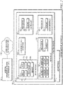
Fig. 2 is a block diagram of a portion of the control system of the patient support apparatus ofFig. 1 ; -
Fig. 3 is a diagrammatic illustration of the interaction between a first frame of the patient support apparatus ofFig. 1 and a second frame supported on load cells supported from the first frame; -
Fig. 4 , is a side view of a portion of the patient support apparatus ofFig. 1 showing a first frame supported on load cells supported on a second frame, the load cells supporting all of the load of the first frame; -
Fig. 5 is a diagrammatic representation of a mattress of the patient support apparatus ofFig. 1 , the mattress including multiple inflatable zones; -
Fig. 6 is a graphical representation of a group of data collected from the patient support apparatus ofFig. 1 , the graphical representation showing the difference between incidents of patient movement detected by the sensors of the patient support apparatus and non -patient movement artifacts detected by the sensors; -
Fig. 7 is a diagrammatic representation of an algorithm for characterizing sensor signals from the patient apparatus ofFig 1 ; and -
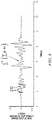
Fig. 8 is a graphical representation of a time series of a sensor signal from a group of sensor of the patient support apparatus ofFig. 1 . - An illustrative
patient support apparatus 10 embodied as a hospital bed is shown inFig. 1 . Thebed 10 ofFig. 1 has aframe 20 which includes abase frame 22 supported oncasters 24. Thestationary base frame 22 further supports aweigh frame 30 that an adjustably positionable mattress supportupper frame 34 supporting amattress 18. Theillustrative mattress 18 is an inflatable patient support surface which includes inflatable zones including ahead zone 36, aseat zone 38,thigh zone 40, and afoot zone 42. Thebed 10 further includes aheadboard 12 at ahead end 46 of thebed 10, afootboard 16 at afoot end 48 of thebed 10, and amovable siderails 14 coupled to theupper frame 34 of thebed 10. Thebed 10 also includes auser interface 54 positioned on one of thesiderails 14. Thebed 10 of the embodiment ofFig. 1 is conventionally configured to adjustably position theupper frame 34 relative to thebase frame 22 to adjust the position of a patient supported on themattress 18. - Conventional structures and devices may be provided to adjustably position the
upper frame 34, and such conventional structures and devices may include, for example, linkages, drives, and other movement members and devices coupled betweenbase frame 22 and theweigh frame 30, and/or betweenweigh frame 30 andupper frame 34. Control of the position of theupper frame 34 andmattress 18 relative to thebase frame 22 or weighframe 30 is controlled, for example, by apatient control pendant 56 oruser interface 54. Theupper frame 34 may, for example, be adjustably positioned in a general incline from thehead end 46 to thefoot end 48 or vice versa. Additionally, theupper frame 34 may be adjustably positioned such that the head section 44 of themattress 18 is positioned between minimum and maximum incline angles, e.g., 0-65 degrees, relative to horizontal or bed flat, and theupper frame 34 may also be adjustably positioned such that a seat section (not shown) of themattress 18 is positioned between minimum and maximum bend angles, e.g., 0-35 degrees, relative to horizontal or bed flat. Those skilled in the art will recognize that theupper frame 34 or portions thereof may be adjustably positioned in other orientations, and such other orientations are contemplated by this disclosure. - In one illustrative embodiment shown diagrammatically in
Fig. 2 , thebed 10 has acontrol system 26 that includes acontroller 28, ascale module 50, anair module 52, and theuser interface 54. In the illustrative embodiment each of thecontroller 28,scale module 50,air module 52, anduser interface 54 includes aprocessor 62 and amemory device 64. Theprocessor 62 andmemory device 64 are shown only with respect to thecontroller 28, but similar structures are used in thescale module 50,air module 52, anduser interface 54. Thememory device 64 includes instructions that, when executed by theprocessor 62, cause theprocessor 62 to perform functions as associated with the particular one ofcontroller 28,scale module 50,air module 52, anduser interface 54. The components of thecontrol system 26 communicate amongst themselves to share information and distribute the functions of thebed 10. Theprocessor 62 of each of thecontroller 28,scale module 50,air module 52, anduser interface 54 is also operable, based on instructions from thememory device 64, to communicate with the others of thecontroller 28,scale module 50,air module 52, anduser interface 54 using a communications protocol. It should be understood that the term processor here includes any microprocessor, microcontroller, processor circuitry, control circuitry, preprogrammed device, or any structure capable of accessing the memory device and executing non-transient instructions to perform the tasks, algorithm, and processed disclosed herein. In the illustrative embodiment, thecontrol system 26 employs a conventional controller area network (CAN) for communications between subsystems, but it should be understood that any of a number of networking and communications solutions could be employed in thecontrol system 26. - The
scale module 50 includes fourload cells mattress 18, theload cells weigh frame 30 and theupper frame 34 as illustrated inFigs. 3 and4 . Eachload cell respective load cell upper frame 34 relative to theweigh frame 30. Some of the structural components of thebed 10 will be designated hereinafter as "right", "left", "head" and "foot" from the reference point of an individual lying on the individual's back on themattress 18 with the individual's head oriented toward thehead end 46 of thebed 10 and the individual's feet oriented toward thefoot end 48 of thebed 10. Following this convention, theload cell 66 is designated as the right head load cell (RHLC) in the figures to represent that theload cell 66 is positioned at the right side of thebed 10 at thehead end 46. Theload cell 68 is designated at the left head load cell (LHLC), theload cell 70 is designated as the right foot load cell (RFLC), and the load cell is designated left foot load cell (LFLC), each following the same convention. - The
scale module 50 includes aprocessor 62 that is in communication with each of therespective load cells load cells memory device 64 is also utilized by thecontroller 28 to store information corresponding to features and functions provided by thebed 10. - A weight distribution of a load among the plurality of
load cells bed 10, variations in each ofload cells mattress 18 relative to theparticular load cell load cells load cells load cells load cell respective load cells respective load cell bed 10. In the present disclosure, the independent signals from each of theload cells - The
air module 52 is the functional controller for themattress 18 and includesprocessor 62 and amemory device 64. Theprocessor 62 is in communication with ablower 106, a manifold 58, and an air pressure sensor assembly 60. Theair module 52 is a conventional structure with the manifold 58 operating under the control of theprocessor 62 to control the flow of air from theblower 106 into and out of thehead zone 36,seat zone 38,thigh zone 40, andfoot zone 42 to control the interface pressure experienced by the patient supported on themattress 18. However, the present disclosure is directed to using the information from sensor assembly 60 to make further inferences regarding motion by the patient supported on themattress 18. The sensor assembly 60 includes separate sensors for measuring the air pressure in each of thehead zone 36,seat zone 38,thigh zone 40, andfoot zone 42. The pressure sensor assembly includes a head zone sensor 82, a seat zone sensor 84, a thigh zone senor 86, and a foot zone sensor 88. While signals from the sensors 82, 84, 86, and 88 are used to control the pressure in the respective zones, applying the principles of the present disclosure, the signals are also useful in making inferences regarding patient movement and, when used synergistically with the information gleaned from the signals from theload cells - Thus, the present disclosure is directed to utilizing the
bed 10, and specifically thescale module 50 andair module 52, as an instrument for measuring the motions of a patient that occupies thebed 10 and characterizing that motion to make inferences about the patient's health. Like all biomedical sensing systems, error can be introduced when the sensor output is affected by various sources of noise. Some sources of noise, such as electrical or stray environmental noise can be mitigated through robust design. However, it is not always possible to mitigate human-caused forces that are imparted to theload cells Fig. 6 is a graph demonstrating the relationship between strictly patient motions, shown as narrow columns atreference 74, to NPMAs, shown as wide columns atreference 76. When NPMAs occur, they are typically much greater in motion magnitude than patient motions. Failure to acknowledge and adjust for the presence of these NPMA results in an inaccurate inference of mobility, self-directed motion, etc. to bias towards patients having much more mobility than they actually have. - The present disclosure is directed to having a practical and accurate analysis and mitigation of NPMAs in real-time. Once determined, load cell signal data that has aspects of NPMA movement can be mitigated or ignored such that true-patient motion can be determined. Referring now, to
Fig. 7 , analgorithm 78 for true motion detection is illustrated, including theNPMA detector function 80. - Through an empirical study that included real-time data collection from video observation of test subject patients synchronized with signals from load cells of the scale module of the bed supporting the test subject patients, the types of motion from the where classified in one of three types: lateral patient motions (LPMs); vertical or self-offloading patient movements (SOs); or non-patient motion artifacts (NPMAs). There were also observations that found that load cell signals varied when there was no patient movement. These artifacts were designated as non-movements (NMs). Permutations of these categories, called "complex movements", also including further categorization into combinations including different directionality of the simple movements was also established.
- The use of the signals from the load cells of a bed, such as
load cells load cells Fig. 1 ) of a range of speeds and magnitudes of motion that are associated with patient motions has been determined. Thus, this allows for the detection of lateral patient motions (LPMs), which are, by definition, detected patient motions which have no vertical component. Any lateral movement will cause the center of gravity of the bed to change during a unit-time interval, proportionally to ratio of the displacement of the amount of mass moved to the amount of mass that remained stationary. Due to this, this feature is self-normalized by patient weight. Note that CG movement in the x and y axis is merged by typical vector addition and the directionality is ignored to establish a factor called CGspeed. It is understood that both patient and non-patient movements will cause the CG to move, for these reasons, and the classifiers and inference models discussed below, any motion that imparts its force to theweigh frame 30 is considered to be a motion. - In a first approach at discriminating NPMAs from LPMs, the patient and the
bed 10 are treated as a closed system. The total energy of the closed system will be constant and conserved over time of typical patient movements. Any energy that is created by the patient as a result of them moving does not change the overall loading of all fourload cells load cell load cells - In contrast, when a caregiver pushes or pulls on the patient or bed 10 (a NPMA), the closed-system is corrupted by an external energy source and the net load on the
load cells bed 10, such as when a person hugs the patient, and in sustained touches of thebed 10, such as when a caregiver leans onbed 10 while doing long procedure. In either case, an additional load is introduced to theload cells load cell bed 10. The value of the transient load, designated as total transient load (TTL) is calculated by subtracting the from the total load measured by theload cells U.S. Pat. No. 10,054,479 - Once the DCSB is established, a simple threshold can be tested to determine whether a TTL is a NPMA or not. The units here are forces, measured in kg, also called kg-force. As part of the test of the threshold, an oscillation in the location of the CG and an effective return of the TTL to zero can be considered to confirm the transient nature of the load to help confirm that the event is a TTL.
- However, there is an exception to this simple approach. Relying just on thresholding TTL moment-by-moment is confounded by self-offloading patient movements (SOs). SOs are large vertical shifts that are an artifact of a patient quickly lifting their core body up using the strength in his legs or arms and then returning to a starting or near starting position. These self-movements cause large momentary changes in TTL and may appear to be an NPMA. Although SOs can cause momentary large shifts from the patient's weight in the closed system, appearing to break it, the closed system is not broken if the response of the system through the entire duration of the motion is considered.
- Referring to
Fig. 8 , the phenomenon of an SO event is illustrated with reference to the variation the sum of the signals from theload cells Fig. 8 . The forces oscillate after the movement occurs in a reaction phase, designated as 2 on the graph inFig. 8 . This is a result of a sort of conservation of energy. The integral or sum of TTL over this event is approximately zero when an SO event is experience, where TTL is negative at points in time, such as thedesignation 2. Under this conservation of energy approach, the SO is detected when any loads induced by the motion of the patient are offset by reactionary loads. - To establish characterization criteria, an empirical study using the synchronized video and load cell signal capture approach discussed above was implemented to gather a mixture of human-generated and human-surrogate test movements were performed. Taking care to vary parameters such as motion speed and magnitude of both patient and NPMA movements, and introducing variability such as different body shapes and strengths in the case of the human subjects, a representative data sample was developed. In the case of the human subjects, three subjects were used a ten-year-old male, 44.5 kg, a fourteen-year-old female, 60 kg, and a forty-year-old male, 101 kg.
- Using the empirically generated test data, an approach was developed to model the absolute total transient load (ATTL), which is defined as:

- Where RHLC, LHLC, RFLC, and LFLC are the values in kg, of the four
load cells weigh frame 30 in some situations. - The conservation of energy theory was modeled using an integral approach and taking the absolute value of the integral as shown below.

- A third modeling equation was derived to calculate CGspeed, which is discussed in theory above, and these equations were used:


- Where t, is the time interval over which the change in the position of the CG moves and where X is the distance between the
left load cells right load cells head load cells foot load cells - The empirically collected test data was manually annotated as patient movement (SO, LPM, or out of bed (OOB)), non-patient motion artifact (NPMA) or no-movement (NM). Patient movements occurring simultaneously with NPMAs were considered labeled as NPMAs, since ultimately it is more important to correctly identify NPMAs when they occur, potentially during patient movement, and throw out all of the data so as not to bias patient movements. To guard against human error of labeling, movements for training and validation were "moved inward", starting 0.5 seconds later and 0.5 before the end as was labeled by humans on all classes. If the (non)movement was greater than 5 seconds, 1 second was used instead of 0.5 seconds. Each feature was calculated in 100 ms intervals, which was determined to be appropriate.
- Table 1 below summarizes the different classes used, the expected responses of the features, and the labeling of the response variables used for training for machine learning. As seen in the table, the features discussed differentiate between the different categories and thus a classifier can be built with them.
Table 1 Simple/ complex Type of motion Motion Class NPMA Class Predictor ATTL Predictor centInt Predictor CGspeed - Nomotion (NM) 0 0 low low low simple LPM 1 0 low low high simple SO 1 0 high high high simple NPMA 1 1 high low high complex LPM OOB 1 0 varies varies high complex LPM NPMA 1 1 varies varies high - Data was visualized to confirm the theoretical behavior suspected, as laid out in Table 1. Although it appears that patient motion is predicted by one variable, and NPMA/non-NPMA is determined by two, an approach that would serialize classifiers by determining if there is ANY motion (patient or non-patient) and pass that data into the classifier that determines the presence of NPMA vs. non NPMA was implemented.
- A binary logistic regression was used to determine a simple threshold that could easily be deployed in an embedded system. A 10-times K-folds cross-validation with an 80/20 ratio split of the training from the validation data was performed. An AUC-ROC curve was prepared to score the performance of the motion classifier classification approach applied at various thresholds for TPR vs. FPR. The validation test resulted in an ROC AUC of 0.99, which is a near-perfect classifier. For this motion detection model, using a threshold of 0.5, 94% of the time true motion is detected and 99% of the time true no motion is detected.
- The coefficients from the empirical model describes the size and direction of the relationship between a predictor feature and the response variables. Using the dataset, the estimated coefficient for the center of gravity speed is -24.43 and change in absolute changes in transient load (ATTL) is -14.57. The intercept of this model is 4.98. Using these coefficients, the following relationship describes motion or no motion:

- Where Pm is the probability there is a motion.
- Due to the binary shape of a sigmoid (shape that is used in logistic regression), this equation represents a line in a two-dimensional feature space, where it can be said that any data point above this line will be motion and any data point below this line will be no-motion group.
- The data was further analyzed with a single factor to test for NPMA events and an estimated threshold coefficient for centInt was 2.87 and the intercept was -4.95. The following equation represents a vertical line indicating that any data point to the right side will be NPMA.

- Where Pn is the probability there is a NPMA event.
- Having successfully established that the features under study could be extracted and applied with confidence in an inference model, a
generalized algorithm 78 for processing sensor data from existing sensors from abed 10 was developed as shown inFig. 7 . At apreprocessing step 90, bed status data and sensor data are pre-processed with sensor data being filtered, such as through low-pass filter. Additional testing is confirmed atstep 92 where data being transferred into aninference engine 94 is validated. Atstep 92, validation include a determination that sensor data being received is consistent with the environment of the bed and patient. In some examples, information may be received from ahospital information system 32 which indicates an expected sensor signal range. For example, validation may test the DCSB against the weight of the patient in thehospital information system 32 to validate that the signals from theload cells hospital information system 32 may include an admission/discharge/transfer (ADT) management system, an electronic medical records system, or a nurse call system. Each of these units of thehospital information system 32 may regularly communicate with others of the systems or may be standalone systems. Thevalidation step 92 may also use other sensors to confirm that a patient is in thebed 10 and generating meaningful data to confirm the validity of thealgorithm 78 in real time. - The filtered data is provided to the
inference engine 94 where at step 96 a first feature extraction is conducted. From the example above, a first feature is extracted to confirm whether there is a threshold state, such as motion or no motion. The CGspeed and ATTL analysis were each proven to be a useful to establish the presence of motion or no motion. In other embodiments, other first features may extracted as the first step in a serial classification approach. Upon extraction of the first feature, the serial classification approach is continued with the features extracted instep 96 advanced to step 98 where baseline data is tested against an extracted first feature to determine whether a threshold has been met that is indicative of motion. If no motion is detected, thealgorithm 78 loops atstep 98 until motion is identified and classification can be conducted. - Once motion is identified at
step 98, the motion is discriminated atstep 80 between NPMA and patient motion of either LPM or SO. If NPMA is identified atstep 80, then the signal data is disregarded. However, confirmation and characterization of LPM or SO atstep 80 is further analyzed atstep 102 to establish a degree of motion. Atstep 102, in the illustrative embodiment, the motion can be distinguished between an egress, a large self-offloading patient movement (SO), a major lateral patient motion (LPM) and/or a small self-offloading patient movement (SO), or a slight lateral patient motion. Once the inference as to the type of patient motion is complete atstep 102, the information is then moved to a database associated with the patient asstep 104. For example, atstep 104 the patient's medical record can be updated, based on the inference identify, objectively, the patient's motion and behavior such as regular self-offloading patient movement (SO), major lateral patient motions (LPMs), slight LPMs, or ingress or egress with or without caregiver assistance. - In addition to simple characterization of the patient motion, between an LPM, SO, egress, or ingress, the data from the
load cells - Using
Equation 3 above to calculate the CGspeed in the X-Y plane can be further processed to calculate the kinetic energy, designated "KE" by the equation:
- Thus, applying the known information, KE can be calculated as:

- Where DCSB is expressed as a mass. By summing the KE over the entire interval of movement by the patient, we can calculate the work the patient does in moving the X-Y plane.

- To calculate the work that is done in the vertical direction, z, the approach is very similar. We calculate KEz by integrating the positive half of the curve shown in
Fig. 8 . We only integrate the upper half of the curve, above the DCSB because the other half of the curve are the reactionary loads that are a response to the work done by the patient to bring the closed-system back to equilibrium. Thus, the calculation of KE in the z-axis is:
- Where ATTL is calculated in
Equation 1 above.
- Having calculated work in all three axes, the total work done by the patient in the movement is simply the sum:

- This calculation of total work with each characterized motion allows an inference as to the health of the patient. If the patient is doing less work in a given time, it is possible to infer that the patient's health has deteriorated as they are not as active. This measurement of work is provides a method of making a second order analysis of patient activity, independent of the patient's actual movement relative to the
bed 10. A patient may cause motion of their body, in the z-axis, for example, without causing actual displacement of their center of gravity relative to thebed 10. In traditional models, this lack of movement would infer the patient to be immobile. Applying the principle of work in multiple dimensions, there is an ability to better characterize the patient's health. - With this in mind, we return to the
control system 26 shown inFig. 2 . Thecontrol system 26 further includes acommunications interface 108 that is operable, under the control of thecontroller 28, to communicate with thehospital information system 32 through acommunications infrastructure 110 to share the patient health characterization, whether that be a mobility score, an activity score, a consciousness score, or any other objective score based on the output from thebed 10 acting as a sensor to objectively measure the work done by the patient and characterizing the type of motions patient is making. - Still further, it is contemplated that if the
controller 28 detects an adverse condition, thecontroller 28 may communicate that adverse condition through thecommunications interface 108 to thehospital information system 32 for action by caregivers. Similarly, thecontroller 28 may communicate an adverse event to theuser interface 54 which may issue an audible or visual alert of the adverse condition. The adverse condition may be based on an acceptable threshold of motion or work. In addition, the adverse condition evaluation may rely solely on a rate of change of patient motion or work. For example, a significant drop in the motion of or work being done by a patient may be an indicator of the deterioration of a patient due to, for example, sepsis, delirium, or a loss of consciousness. - Although this disclosure refers to specific embodiments, it will be understood by those skilled in the art that various changes in form and detail may be made.
- Embodiments of the invention can be described with reference to the following numbered clauses, with preferred features laid out in the dependent clauses:
- 1. A method of characterizing the condition of a patient supported on a patient support apparatus having a plurality of load cells that support the patient load, the method comprising:
- receive a separate signal from each of the plurality of load cells;
- process the signals to identify, based on transient changes in the forces measured by each of the plurality of load cells, motion of the patient that does not result in a change of position of the patient on the patient support apparatus;
- characterize the nature of the patient motion; and
- based on the characterization of the patient motion automatically update a patient profile in a patient record to reflect the characterization of the patient motion.
- 2. The method of
clause 1, further comprising:
determining, based on the transient changes in the forces measured by the load cells, the magnitude of motion of a least a portion of the patient in a vertical direction. - 3. The method of
clause 2, further comprising:
calculating the work done by the patient in the vertical direction to characterize the patient motion. - 4. The method of any preceding clause, further comprising:
- calculating the work done by the patient;
- distinguishing between motion that results in movement of the patient's mass to a different position on the patient support apparatus from motion that does not result in movement of the patient's mass to a different position on the patient support apparatus; and updating the patient profile to reflect the net movement of the patient and the motion that does not result in movement of the patient's mass to a different position on the patient support apparatus.
- 5. The method of any preceding clause, further comprising:
calculating a speed of movement of the center of gravity of the patient in the plane that is orthogonal to the direction of gravity to further determine the amount of work done by the patient moving in the plane that is orthogonal to the direction of gravity. - 6. The method of any preceding clause, further comprising:
- calculate the work done by a patient that does not result in movement in the plane that is orthogonal to the direction of gravity; and
- updating the patient profile to reflect the work done by the patient.
- 7. The method of
clause 6, further comprising:
determining the work that is done to move the patient in the direction of gravity and the work that is done to move the patient in the plane that is orthogonal to the direction of gravity; and updating the patient profile to reflect the total work done by the patient. - 8. The method of any preceding clause, further comprising:
- distinguishing between patient motion and non-patient motion artifacts; and
- disregarding non-patient motion artifacts when updating the patient profile.
- 9. The method of clause 8, further comprising:
determining the existence of a non-patient motion artifact by closed system analysis that detects that an additional load has been added to the load cells. - 10. The method of either clause 8 or clause 9, further comprising:
determining the additional load using an analysis of the sum of the values detected by the load cells to determine if the net load of the load cells has been affected by an external input. - 11. A method of characterizing the condition of a patient supported on a patient support apparatus having a plurality of load cells that support the patient load, the patient support apparatus having a patient support surface with an x-axis, a y-axis, and a z-axis, the method comprising:
- receiving a separate signal from each of the plurality of load cells;
- calculating a speed of movement of the center of gravity of the patient in the plane defined by the x-axis and y-axis by using the forces measured in the x-axis and y-axis, and
- notifying a caregiver of a patient status based on the speed of movement.
- 12. The method as recited in clause 11, further comprising calculating total work done by the patient in the plane defined by the x-axis and y-axis based on the speed of movement of the center of gravity.
- 13. The method as recited in
clause 12, further comprising calculating a speed of movement of the patient in z-axis by using the forces measured in the z-axis. - 14. The method as recited in any one of clauses 11 to 13, further comprising calculating a speed of movement of the patient in z-axis by using the forces measured in the z-axis.
- 15. A method of characterizing the condition of a patient supported on a patient support apparatus having a plurality of load cells that support the patient load, the patient support apparatus having a patient support surface with an x-axis, a y-axis, and a z-axis, the method comprising:
- receiving a separate signal from each of the plurality of load cells;
- processing the signals to identify changes in the forces measured by each of the plurality of load cells;
- calculating total work done by the patient based on the changes in force; and
- notifying a caregiver of a patient status based on the total work done.
- 16. The method as recited in clause 15, further comprising calculating total work done by the patient in the plane defined by the x-axis and y-axis based on the speed of movement of the center of gravity.
- 17. The method as recited in
clause 16, further comprising calculating a speed of movement of the patient in z-axis by using the forces measured in the z-axis. - 18. The method as recited in any one of clauses 15 to 17, further comprising calculating a speed of movement of the patient in z-axis by using the forces measured in the z-axis.
- 19. A method of characterizing the condition of a patient supported on a patient support apparatus having a plurality of load cells that support the patient load, the patient support apparatus having a patient support surface with an x-axis, a y-axis, and a z-axis, the method comprising:
- receiving a separate signal from each of the plurality of load cells;
- processing the signals to identify any changes in forces in the x-axis, y-axis, and z-axis;
- calculating at least one of speed of the center of gravity, kinetic energy of the patient, and total work done by the patient, based on the changes in forces; and
- notifying a caregiver of a patient status based on the calculation.
- 20. The method as recited in clause 19, further comprising calculating total work done by the patient in the plane defined by the x-axis and y-axis based on the speed of movement of the center of gravity.
- 21. The method as recited in
clause 20, further comprising calculating a speed of movement of the patient in z-axis by using the forces measured in the z-axis. - 22. The method as recited in any one of clauses 19 to 21, further comprising calculating a speed of movement of the patient in z-axis by using the forces measured in the z-axis.
Claims (15)
- A patient support apparatus comprisinga plurality of load cells,a frame supported on the load cells such that the load of the frame is measured by the load cells, the frame configured to support a patient supported on the patient support apparatus such that the load of the patient is transferred through the plurality of load cells,a control system including a controller, the controller operable to receive a separate signal from each of the plurality of load cells, process the signals to identify, based on transient changes in the forces measured by each of the plurality of load cells, motion of the patient, characterize the motion of the patient, and, based on the characterization, update a patient profile in a patient record to reflect the characterization of the patient motion.
- The patient support apparatus of claim 1, wherein the transient changes in the forces measured by the load cells are indicative of motion of a least a portion of the patient in a vertical direction.
- The patient support apparatus of claim 2, wherein the controller is operable to calculate the work done by the patient in the vertical direction to characterize the patient motion.
- The patient support apparatus of any preceding claim, wherein the controller is operable to calculate the work done by the patient and distinguish between motion that results in movement of the patient's mass to a different position on the patient support apparatus from motion that does not result in movement of the patient's mass to a different position on the patient support apparatus and updates the patient profile to reflect the net movement of the patient and the motion that does not result in movement of the patient's mass to a different position on the patient support apparatus.
- The patient support apparatus of any preceding claim, wherein the controller is operable to calculate a speed of movement of the center of gravity of the patient in the plane that is orthogonal to the direction of gravity to further determine the amount of work done by the patient moving in the plane that is orthogonal to the direction of gravity.
- The patient support apparatus of claim 5, wherein the controller is operable to calculate the work done by a patient that does not result in movement in the plane that is orthogonal to the direction of gravity.
- The patient support apparatus of claim 6, wherein the controller is operable to determine the work that is done to move the patient in the direction of gravity and the work that is done to move the patient in the plane that is orthogonal to the direction of gravity and updates the patient profile to reflect the total work done by the patient.
- The patient support apparatus of claim 7, wherein the controller is operable to distinguish between patient motion and non-patient motion artifacts and disregards non-patient motion artifacts when updating the patient profile.
- The patient support apparatus of claim 8, wherein the controller is operable to determine the existence of a non-patient motion artifact by closed system analysis that detects that an additional load has been added to the load cells.
- The patient support apparatus of claim 9, wherein the additional load is determined using an analysis of the sum of the values detected by the load cells to determine if the net load of the load cells has been affected by an external input.
- A patient support apparatus as claimed in any preceding claim comprisinga second frame, andthe plurality of load cells positioned on the second frame, whereinthe controller is operable to identify motion of the patient that does not result in relative movement of the patient relative to the second frame, the motion of the patient being further processed to characterize the nature of the patient motion.
- A method of characterizing the condition of a patient supported on a patient support apparatus having a plurality of load cells that support the patient load, the method comprising:receive a separate signal from each of the plurality of load cells;process the signals to identify, based on transient changes in the forces measured by each of the plurality of load cells, motion of the patient that does not result in a change of position of the patient on the patient support apparatus;characterize the nature of the patient motion; andbased on the characterization of the patient motion automatically update a patient profile in a patient record to reflect the characterization of the patient motion.
- The method of claim 12, further comprising:calculating the work done by the patient;distinguishing between motion that results in movement of the patient's mass to a different position on the patient support apparatus from motion that does not result in movement of the patient's mass to a different position on the patient support apparatus; andupdating the patient profile to reflect the net movement of the patient and the motion that does not result in movement of the patient's mass to a different position on the patient support apparatus.
- The method of either claim 12 or claim 13, further comprising:
calculating a speed of movement of the center of gravity of the patient in the plane that is orthogonal to the direction of gravity to further determine the amount of work done by the patient moving in the plane that is orthogonal to the direction of gravity. - The method of any one of claims 12 to 14, further comprising:calculate the work done by a patient that does not result in movement in the plane that is orthogonal to the direction of gravity; andupdating the patient profile to reflect the work done by the patient.
Applications Claiming Priority (1)
| Application Number | Priority Date | Filing Date | Title |
|---|---|---|---|
| US202163154055P | 2021-02-26 | 2021-02-26 |
Publications (1)
| Publication Number | Publication Date |
|---|---|
| EP4050620A1 true EP4050620A1 (en) | 2022-08-31 |
Family
ID=80448480
Family Applications (1)
| Application Number | Title | Priority Date | Filing Date |
|---|---|---|---|
| EP22158232.3A Pending EP4050620A1 (en) | 2021-02-26 | 2022-02-23 | Universal load beam features that characterize patient motion in three dimensions in a hospital bed |
Country Status (2)
| Country | Link |
|---|---|
| US (1) | US12097154B2 (en) |
| EP (1) | EP4050620A1 (en) |
Citations (4)
| Publication number | Priority date | Publication date | Assignee | Title |
|---|---|---|---|---|
| US20160106345A1 (en) * | 2014-10-17 | 2016-04-21 | Stryker Corporation | Person support apparatuses with motion monitoring |
| US10054479B2 (en) | 2015-05-05 | 2018-08-21 | Hill-Rom Services, Inc. | Bed with automatic weight offset detection and modification |
| US20190183427A1 (en) * | 2017-12-19 | 2019-06-20 | Hill-Rom Services, Inc. | Method and apparatus for patient bed load cell signal monitoring for patient movement classification |
| EP3912609A1 (en) * | 2020-04-30 | 2021-11-24 | Hill-Rom Services, Inc. | Mobility sensing using load cells |
Family Cites Families (27)
| Publication number | Priority date | Publication date | Assignee | Title |
|---|---|---|---|---|
| US7987069B2 (en) * | 2007-11-12 | 2011-07-26 | Bee Cave, Llc | Monitoring patient support exiting and initiating response |
| US8882684B2 (en) * | 2008-05-12 | 2014-11-11 | Earlysense Ltd. | Monitoring, predicting and treating clinical episodes |
| US8752220B2 (en) * | 2009-07-10 | 2014-06-17 | Hill-Rom Services, Inc. | Systems for patient support, monitoring and treatment |
| US8437876B2 (en) | 2009-08-07 | 2013-05-07 | Hill-Rom Services, Inc. | Patient health based support apparatus configuration |
| US8525680B2 (en) | 2009-09-18 | 2013-09-03 | Hill-Rom Services, Inc. | Apparatuses for supporting and monitoring a condition of a person |
| US20110301432A1 (en) | 2010-06-07 | 2011-12-08 | Riley Carl W | Apparatus for supporting and monitoring a person |
| US8350709B2 (en) | 2010-03-31 | 2013-01-08 | Hill-Rom Services, Inc. | Presence detector and occupant support employing the same |
| US8432287B2 (en) | 2010-07-30 | 2013-04-30 | Hill-Rom Services, Inc. | Apparatus for controlling room lighting in response to bed exit |
| US20120259245A1 (en) | 2011-04-08 | 2012-10-11 | Receveur Timothy J | Person support apparatus with activity and mobility sensing |
| US9295600B2 (en) | 2011-04-08 | 2016-03-29 | Hill-Rom Services, Inc. | Person support apparatus with activity and mobility sensing |
| US20140352060A1 (en) * | 2012-01-20 | 2014-12-04 | Showa Denko K.K. | Bed having load detection function and load detector for bed |
| US9295390B2 (en) | 2012-03-02 | 2016-03-29 | Hill-Rom Services, Inc. | Facial recognition based monitoring systems and methods |
| US9213956B2 (en) | 2012-03-14 | 2015-12-15 | Hill-Rom Services, Inc. | Algorithm for predicting and mitigating adverse events |
| US9358168B2 (en) | 2012-09-04 | 2016-06-07 | Hill-Rom Services, Inc. | Patient position detection for patient support surface |
| US10219725B2 (en) | 2012-09-04 | 2019-03-05 | Hill-Rom Services, Inc. | Patient mobility surface assessment system and method |
| US9383250B2 (en) * | 2012-11-05 | 2016-07-05 | Hill-Rom Services, Inc. | Automatic weight offset calculation for bed scale systems |
| JP6134214B2 (en) | 2013-06-28 | 2017-05-24 | 住友理工株式会社 | Bed sensor and bed detection method |
| US10786408B2 (en) * | 2014-10-17 | 2020-09-29 | Stryker Corporation | Person support apparatuses with exit detection systems |
| EP3189823B1 (en) | 2016-01-07 | 2020-12-16 | Hill-Rom Services, Inc. | Support surface useful life monitoring |
| US20170224253A1 (en) | 2016-02-10 | 2017-08-10 | Covidien Lp | Patient bed-exit prediction and detection |
| US10010271B2 (en) * | 2016-04-15 | 2018-07-03 | Hill-Rom Services, Inc. | Method and apparatus for monitoring and reporting on the status of an occupant of an occupant support |
| AU2017350714B2 (en) | 2016-10-24 | 2022-08-04 | Hill-Rom Services, Inc. | System for predicting egress from an occupant support |
| US10548476B2 (en) * | 2017-08-17 | 2020-02-04 | Welch Allyn, Inc. | Patient monitoring system |
| US10297143B1 (en) | 2018-03-21 | 2019-05-21 | International Business Machines Corporation | Detecting quality of physiologic data using contact pressure data for alarm generation |
| AU2019358908A1 (en) | 2019-02-12 | 2021-10-07 | Sleep Number Corporation | Multidimensional multivariate multiple sensor system |
| US12548674B2 (en) | 2019-12-31 | 2026-02-10 | Hill-Rom Services, Inc. | Technologies for inferring a patient condition using machine learning |
| US12527524B2 (en) | 2020-03-30 | 2026-01-20 | Hill-Rom Services, Inc. | Bed-based ballistocardiogram apparatus and method |
-
2022
- 2022-02-21 US US17/676,308 patent/US12097154B2/en active Active
- 2022-02-23 EP EP22158232.3A patent/EP4050620A1/en active Pending
Patent Citations (4)
| Publication number | Priority date | Publication date | Assignee | Title |
|---|---|---|---|---|
| US20160106345A1 (en) * | 2014-10-17 | 2016-04-21 | Stryker Corporation | Person support apparatuses with motion monitoring |
| US10054479B2 (en) | 2015-05-05 | 2018-08-21 | Hill-Rom Services, Inc. | Bed with automatic weight offset detection and modification |
| US20190183427A1 (en) * | 2017-12-19 | 2019-06-20 | Hill-Rom Services, Inc. | Method and apparatus for patient bed load cell signal monitoring for patient movement classification |
| EP3912609A1 (en) * | 2020-04-30 | 2021-11-24 | Hill-Rom Services, Inc. | Mobility sensing using load cells |
Also Published As
| Publication number | Publication date |
|---|---|
| US12097154B2 (en) | 2024-09-24 |
| US20220273509A1 (en) | 2022-09-01 |
Similar Documents
| Publication | Publication Date | Title |
|---|---|---|
| Alarifi et al. | Killer heuristic optimized convolution neural network-based fall detection with wearable IoT sensor devices | |
| EP3355784B1 (en) | Biometric information monitoring system | |
| US20240268707A1 (en) | Injury prevention system for remotely monitoring subjects | |
| US20120253233A1 (en) | Algorithm for quantitative standing balance assessment | |
| EP2687157A2 (en) | Quantitative falls risk assessment through inertial sensors and pressure sensitive platform | |
| US20210161462A1 (en) | Patient support apparatuses with mobility assessment | |
| Shawen et al. | Fall detection in individuals with lower limb amputations using mobile phones: machine learning enhances robustness for real-world applications | |
| Clemente et al. | Helena: Real-time contact-free monitoring of sleep activities and events around the bed | |
| EP3528693B1 (en) | System for predicting egress from an occupant support | |
| Aziz et al. | Identifying the number and location of body worn sensors to accurately classify walking, transferring and sedentary activities | |
| WO2014153665A1 (en) | System and method for monitoring a subject | |
| Amiroh et al. | Intelligent system for fall prediction based on accelerometer and gyroscope of fatal injury in geriatric | |
| Shaima | Fall detection and monitoring using machine learning: a comparative study | |
| EP4049643A1 (en) | Apparatus and method for discriminating patient movement on a support apparatus between self movement and assisted movement | |
| Barralon et al. | Classification of daily physical activities from a single kinematic sensor | |
| Febriana et al. | Sleep monitoring system based on body posture movement using Microsoft Kinect sensor | |
| US12097154B2 (en) | Universal load cell features that characterize patient motion in three dimensions in a hospital bed | |
| Garg et al. | An accelerometer based fall detection system using deep neural network | |
| US12558002B2 (en) | Bed scale noise compensation using a reference transducer | |
| US10478066B2 (en) | System and method for detection of cravings in individuals with addiction | |
| US20230210448A1 (en) | Skin shear detection for hospital beds | |
| Howedi et al. | Accelerometer-based human fall detection using fuzzy entropy | |
| Breuss et al. | Sleep position detection for closed-loop treatment of sleep-related breathing disorders | |
| Kishimoto et al. | Estimation of sleeping posture for M-Health by a wearable tri-axis accelerometer | |
| US20190216367A1 (en) | Patient monitoring system using wearable sensors with automated template matching |
Legal Events
| Date | Code | Title | Description |
|---|---|---|---|
| PUAI | Public reference made under article 153(3) epc to a published international application that has entered the european phase |
Free format text: ORIGINAL CODE: 0009012 |
|
| STAA | Information on the status of an ep patent application or granted ep patent |
Free format text: STATUS: THE APPLICATION HAS BEEN PUBLISHED |
|
| AK | Designated contracting states |
Kind code of ref document: A1 Designated state(s): AL AT BE BG CH CY CZ DE DK EE ES FI FR GB GR HR HU IE IS IT LI LT LU LV MC MK MT NL NO PL PT RO RS SE SI SK SM TR |
|
| STAA | Information on the status of an ep patent application or granted ep patent |
Free format text: STATUS: REQUEST FOR EXAMINATION WAS MADE |
|
| 17P | Request for examination filed |
Effective date: 20230228 |
|
| RBV | Designated contracting states (corrected) |
Designated state(s): AL AT BE BG CH CY CZ DE DK EE ES FI FR GB GR HR HU IE IS IT LI LT LU LV MC MK MT NL NO PL PT RO RS SE SI SK SM TR |
|
| STAA | Information on the status of an ep patent application or granted ep patent |
Free format text: STATUS: EXAMINATION IS IN PROGRESS |
|
| 17Q | First examination report despatched |
Effective date: 20250610 |
|
| GRAP | Despatch of communication of intention to grant a patent |
Free format text: ORIGINAL CODE: EPIDOSNIGR1 |
|
| STAA | Information on the status of an ep patent application or granted ep patent |
Free format text: STATUS: GRANT OF PATENT IS INTENDED |
|
| INTG | Intention to grant announced |
Effective date: 20260205 |