EP4050344B1 - Bestimmung des betriebszustands eines fahrzeugs durch teilchendetektion - Google Patents
Bestimmung des betriebszustands eines fahrzeugs durch teilchendetektion Download PDFInfo
- Publication number
- EP4050344B1 EP4050344B1 EP22155372.0A EP22155372A EP4050344B1 EP 4050344 B1 EP4050344 B1 EP 4050344B1 EP 22155372 A EP22155372 A EP 22155372A EP 4050344 B1 EP4050344 B1 EP 4050344B1
- Authority
- EP
- European Patent Office
- Prior art keywords
- particle
- vehicle
- operating state
- sample volume
- particles
- Prior art date
- Legal status (The legal status is an assumption and is not a legal conclusion. Google has not performed a legal analysis and makes no representation as to the accuracy of the status listed.)
- Active
Links
Images


Classifications
-
- G—PHYSICS
- G01—MEASURING; TESTING
- G01P—MEASURING LINEAR OR ANGULAR SPEED, ACCELERATION, DECELERATION, OR SHOCK; INDICATING PRESENCE, ABSENCE, OR DIRECTION, OF MOVEMENT
- G01P5/00—Measuring speed of fluids, e.g. of air stream; Measuring speed of bodies relative to fluids, e.g. of ship, of aircraft
- G01P5/18—Measuring speed of fluids, e.g. of air stream; Measuring speed of bodies relative to fluids, e.g. of ship, of aircraft by measuring the time taken to traverse a fixed distance
- G01P5/20—Measuring speed of fluids, e.g. of air stream; Measuring speed of bodies relative to fluids, e.g. of ship, of aircraft by measuring the time taken to traverse a fixed distance using particles entrained by a fluid stream
-
- G—PHYSICS
- G08—SIGNALLING
- G08G—TRAFFIC CONTROL SYSTEMS
- G08G5/00—Traffic control systems for aircraft
- G08G5/70—Arrangements for monitoring traffic-related situations or conditions
- G08G5/76—Arrangements for monitoring traffic-related situations or conditions for monitoring atmospheric conditions
-
- B—PERFORMING OPERATIONS; TRANSPORTING
- B64—AIRCRAFT; AVIATION; COSMONAUTICS
- B64D—EQUIPMENT FOR FITTING IN OR TO AIRCRAFT; FLIGHT SUITS; PARACHUTES; ARRANGEMENT OR MOUNTING OF POWER PLANTS OR PROPULSION TRANSMISSIONS IN AIRCRAFT
- B64D43/00—Arrangements or adaptations of instruments
-
- G—PHYSICS
- G01—MEASURING; TESTING
- G01N—INVESTIGATING OR ANALYSING MATERIALS BY DETERMINING THEIR CHEMICAL OR PHYSICAL PROPERTIES
- G01N15/00—Investigating characteristics of particles; Investigating permeability, pore-volume or surface-area of porous materials
- G01N15/02—Investigating particle size or size distribution
- G01N15/0205—Investigating particle size or size distribution by optical means
-
- G—PHYSICS
- G01—MEASURING; TESTING
- G01N—INVESTIGATING OR ANALYSING MATERIALS BY DETERMINING THEIR CHEMICAL OR PHYSICAL PROPERTIES
- G01N15/00—Investigating characteristics of particles; Investigating permeability, pore-volume or surface-area of porous materials
- G01N15/10—Investigating individual particles
- G01N15/14—Optical investigation techniques, e.g. flow cytometry
-
- G—PHYSICS
- G01—MEASURING; TESTING
- G01P—MEASURING LINEAR OR ANGULAR SPEED, ACCELERATION, DECELERATION, OR SHOCK; INDICATING PRESENCE, ABSENCE, OR DIRECTION, OF MOVEMENT
- G01P13/00—Indicating or recording presence, absence, or direction, of movement
- G01P13/02—Indicating direction only, e.g. by weather vane
- G01P13/025—Indicating direction only, e.g. by weather vane indicating air data, i.e. flight variables of an aircraft, e.g. angle of attack, side slip, shear, yaw
-
- G—PHYSICS
- G01—MEASURING; TESTING
- G01P—MEASURING LINEAR OR ANGULAR SPEED, ACCELERATION, DECELERATION, OR SHOCK; INDICATING PRESENCE, ABSENCE, OR DIRECTION, OF MOVEMENT
- G01P5/00—Measuring speed of fluids, e.g. of air stream; Measuring speed of bodies relative to fluids, e.g. of ship, of aircraft
- G01P5/26—Measuring speed of fluids, e.g. of air stream; Measuring speed of bodies relative to fluids, e.g. of ship, of aircraft by measuring the direct influence of the streaming fluid on the properties of a detecting optical wave
-
- G—PHYSICS
- G01—MEASURING; TESTING
- G01N—INVESTIGATING OR ANALYSING MATERIALS BY DETERMINING THEIR CHEMICAL OR PHYSICAL PROPERTIES
- G01N15/00—Investigating characteristics of particles; Investigating permeability, pore-volume or surface-area of porous materials
- G01N15/02—Investigating particle size or size distribution
- G01N15/0205—Investigating particle size or size distribution by optical means
- G01N2015/0238—Single particle scatter
-
- G—PHYSICS
- G01—MEASURING; TESTING
- G01N—INVESTIGATING OR ANALYSING MATERIALS BY DETERMINING THEIR CHEMICAL OR PHYSICAL PROPERTIES
- G01N15/00—Investigating characteristics of particles; Investigating permeability, pore-volume or surface-area of porous materials
- G01N15/10—Investigating individual particles
- G01N15/14—Optical investigation techniques, e.g. flow cytometry
- G01N2015/1486—Counting the particles
Definitions
- Detecting particulates in fluids typically utilizes a light source to illuminate particles, a collection of optics to receive scattered light from the particles and a detector to convert the collected light into an electrical particle signals that can be processed, digitized, etc.
- the particle signals can be used to derive information regarding particles in a sample volume such as particle size and concentration.
- the particle signals may also allow for the calculation of other parameters which may be of interest in determining vehicle operating states in an environment. For aerospace applications, deriving air data parameters for use as a backup system or in data fusion with a traditional air data probe may be of particular interest.
- EP 3 339 184 A1 describes a method of determining the onset of a stall condition in a vehicle that is provided.
- EP 3 290 674 A1 describes methods and apparatus to control thrust ramping of an aircraft engine are disclosed.
- EP 3 301 456 A1 describes an aircraft comprising a fuselage; and a laser transceiver configured to transmit one or more laser light beams, wherein the laser transceiver for measuring an air data parameter is mounted to the aircraft at a waterline location along the center of the fuselage of the aircraft.
- US 2019/302141 A1 describes an optical air data system for an air vehicle including a LIDAR module and a data processing module.
- Embodiments provide a vehicle operating state particle detection system that determines an operating state of vehicle by comparing particle information in sample volumes collected by particle detectors.
- system for determining a vehicle operating state includes at least two particle detectors, a controller and a memory.
- a sample volume used by each particle detector of the at least two particle detectors is configured to be collected in a different location relative to the vehicle than another sample volume used by another particle detector of the at least two particle detectors.
- at least one sample volume is configured to be collected in an environment where particles being detected by an associated particle detector are disturbed by the vehicle when the vehicle is in motion.
- the controller is in communication with the at least two particle detectors.
- the controller is configured to determine at least one operating state of the vehicle based at least in part on a comparison of output signals of the at least two particle detectors.
- the controller is configured to use particle velocity and at least one of measurement of a particle size distribution, and measurement of particle concentration as a function of distance from the vehicle in determining the at least one state of the vehicle.
- the at least one memory is used to store at least operating instructions implemented by the controller in determining the at least one operating state of the vehicle.
- a method of operating a system for determining an operating state using particle detection includes obtaining at least a first sample volume of particles and a second sample volume of particles, wherein the first sample volume is collected in an environment where particles being detected by a particle detector are disturbed by the vehicle by a change in operating state of the vehicle and the second sample volume is collected in an environment where the particles in the second sample volume being detected will be disturbed in a different manner than the particles in the first sample volume by the change in operating state of the vehicle; comparing particles in the at least first sample volume and the second sampled volume; and determining at least one operating state of the vehicle based on the comparison, wherein the comparison is made on the basis of measurements of particle velocity and at least one of measurement of a particle size distribution, and measurement of particle concentration as a function of distance from the vehicle.
- Embodiments provide system for determining a vehicle operating state that can be used to determine a then current operating state of the vehicle.
- An operating state of a vehicle defines how the vehicle is behaving or interacting in an environment.
- a determined operating state may be used as a backup and/or augment determined operating state provided by vehicle sensors such as, but not limited to, air data sensor systems in an avionic application.
- vehicle sensors such as, but not limited to, air data sensor systems in an avionic application.
- a particle detector vehicle operating state determining system has different failure modes than air data sensor system of an aircraft its application as a backup is very beneficial. For example, the more particles measured, the more accurate an estimate of air data parameters. Further environments with high particulate counts are also potential icing environments, where traditional air data probes fail.
- the air data parameters derived from the particulate sensor may also be used to hint at navigation solutions or otherwise bound navigation solutions provided by air data systems, making the solutions more accurate and robust or to cross check for inconsistencies with the existing air data parameters.
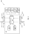
- FIG. 1 a block diagram of a system 100 for determining an operating state using particle detection of an example of an embodiment is illustrated.
- Figure 1 illustrates a vehicle 102 that includes the system 100 for determining an operating state using particle detection.
- the system 100 includes at least one controller 104 and at least one memory 106.
- the controller 104 may include any one or more of a processor, microprocessor, a digital signal processor (DSP), an application specific integrated circuit (ASIC), a field program gate array (FPGA), or equivalent discrete or integrated logic circuitry.
- DSP digital signal processor
- ASIC application specific integrated circuit
- FPGA field program gate array
- controller 104 may include multiple components, such as any combination of one or more microprocessors, one or more controllers, one or more DSPs, one or more ASICs, one or more FPGAs, as well as other discrete or integrated logic circuitry.
- the functions attributed to the controller 104 herein may be embodied as software, firmware, hardware or any combination thereof.
- the controller 104 may be part of a system controller or a component controller.
- the memory 106 may include computer-readable operating instructions that, when executed by the controller 104 provides functions of the system 100 for determining an operating state using particle detection. Such functions may include the functions of determining a then current operational state of the vehicle as described below.
- the computer readable instructions may be encoded within the memory 106.
- Memory 106 is an appropriate non-transitory storage medium or media including any volatile, nonvolatile, magnetic, optical, or electrical media, such as, but not limited to, a random access memory (RAM), read-only memory (ROM), nonvolatile RAM (NVRAM), electrically-erasable programmable ROM (EEPROM), flash memory, or any other storage medium.
- RAM random access memory
- ROM read-only memory
- NVRAM nonvolatile RAM
- EEPROM electrically-erasable programmable ROM
- flash memory or any other storage medium.
- the system 100 for determining an operating state using particle detection in this example includes a plurality of sensors, 110 through 120-4, that provide information to the controller in determining a current vehicle operating state.
- the sensors in this example includes a global position system (GPS) 110 to provide location information, an inertial measurement system (IMS) 112 to provide at least directional acceleration information and an altitude sensor 114 to provide altitude information.
- GPS global position system
- IMS inertial measurement system
- altitude sensor 114 to provide altitude information.
- the sensors further may include air data sensors 116 to provide air data measurements that may include temperature and air speed information.
- the air data sensors may be, but are not limited to, mechanical vanes and pitot-static systems.
- Other types of sensors 118 may also be used that provide vehicle operating state information such as LiDAR echo measurement sensors.
- Information from these sensors alone or in combination are used by the controller 104 in determining a current operational state of the vehicle.
- an input/output 108 may provide a user an input for at least the operating instructions stored in the memory 106 and a system output that outputs controller determinations.
- the input/output 108 may include a vehicle operating control system configured to use, at least in part, determinations of a vehicle operating state from the controller 104.
- the system 100 for determining an operating state using particle detection further includes particle detectors 120-1 through 120-4 which, as described below, may augment operational state determinations by using a system with dissimilar failure modes or to cross check for inconsistencies etc.
- Each particle detectors 120-1, 120-2, 120-3 and 120-4 is associated with a focal length 122-1, 122-2, 122-3 and 122-4 of receive optics of its associated particle detector 120 120-1, 120-2, 120-3 and 120-4.
- the particle sensors may generally be referenced by 120 and the associated focal length may generally be referenced by 122.
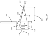
- FIG. 2A a block diagram of a particle detector 120 and an associated focal length 122 is provided for illustrative purposes.
- the particle detector 120 example of Figure 2B is illustrated as including a sensor controller 227, such as a processor or the like, that controls operation of a laser 225 and generates a particle sensor signal 221 based on an output from an optical system 227.
- the partial sensor signal 221 is provided to controller 104 of the system 100.
- the laser 226 generates laser light 226 that is directed out from the particle sensor 120 into particles away from the vehicle 102, such as particles away from a skin 204 of an aircraft. The particles reflect some of the laser light back towards the particle sensor.
- the focal length 122 of the receive optics in the optic system 227 allows for only reflected light back, that is within the cone of light 228, to be collected by the receive optics in the optic system 227. Hence, the focal length 122 of the receive optics in the optic system 227 is selected to monitor particles at a select distance from the particle sensor 120 or a surface of a vehicle 102.
- the use of at least two particle detectors 120 at different locations in relation to the vehicle 102 provides air data parameters based on relative sensor measurements that can be used to determine a current vehicle operating state.
- Each detector 120 may measure the particle content in a sample volume at a finite distance from a surface of a vehicle 102, such as a fuselage of an aircraft in an avionic example, where at least one sample volume used by at least one particle detector 120 was taken in an airflow region that was disturbed by the aircraft 102.
- the movement of the aircraft 102 through the atmosphere disturbs the surrounding environment, including the velocity and concentration of particles in the atmosphere.
- the magnitude of this disturbance is dependent on many flight parameters. Examples of such flight parameters are air speed, air density, angle of attack and side slip angle.
- Some, embodiments take advantage of disturbances by positioning 2 or more particle detectors 120 at various locations on the aircraft fuselage and matching the sensor measurements against a calibration covering the flight envelope of the aircraft.
- the calibration may be derived from modeling (e.g. computational fluid dynamics), direct measurement during flight test with adequate reference sensors, and/or tests in a wind tunnel.
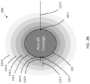
- FIG. 2B illustrates an aircraft fuselage with disturbance areas 200. Further, Figure 2B illustrates a free stream comparison application layout of a configuration of particle sensors 120 in an aircraft example.
- the aircraft fuselage with disturbance areas 200 includes an aircraft fuselage 202 with attached particle detectors 120-5, 120-6 and 120-7. Focal lengths 122-5, 122-6 and 122-7 associated with particle detectors 120-5, 120-6 and 120-7 are also illustrated.
- particle detectors 120-6 is opposably positioned on the aircraft fuselage 202 in relation to particle detectors 120-5. Further illustrated are the disturbance areas 210-1, 210-2, 210-3, and 210-4 with particle concentration gradients found around the aircraft fuselage 202.
- Each particle concentration gradient in the disturbance areas 210-1, 210-2, 210-3 and 210-4 represents levels of particle disturbance as the result of the movement of aircraft fuselage 202 through the particles.
- the aircraft fuselage 202 and hence the aircraft it is associated with is generally traveling in a straight path.
- particle detector 102-5 via its focal length 122-5, measures particles in a sample volume that is outside the disturbance areas while particle detector 102-6, via its focal length 122-6, measures particles in a sample volume that is within disturbance area 210-2.
- All parameters measured by particle detector 120-6 may be normalized by respective free stream values measured by sensor detector 120-5 thereby removing a variation due to total particle load. This normalized data can then be matched to the best fit flight conditions from the calibration.
- additional particle sensors can be added which either sample volumes at different distances from the fuselage 202, different locations on the fuselage 202, or both.
- FIG. 2B illustrates a particle concentration verses distance from fuselage graph 230.
- Graph 230 illustrates an example that uses a particle concentration parameter. Distances from the fuselage 202 are indicated by particle detectors 120-5, 120-6 and 120-7 in graph 230.
- particle detectors 120-8 and 120-9 with nominally identical focal lengths 122-8 and 122-9 may be placed at identical locations on opposite sides of a waterline of the aircraft fuselage 202 in a slide slip angle determination configuration 300 as illustrated in Figure 3A .
- the slide slip angle determination configuration 300 is meant to isolate changes due to a side slip angle (SSA).
- SSA side slip angle
- the measurements from the two sensors should be nominally identical, different only by measurement errors.
- the gradients of deviations, disturbance areas 210-1, 210-2, 210-3, and 210-4, from free stream behavior should tilt to one side, inducing a differential measurement between the two sensors 120-8 and 120-9.
- particle detector 120-9 measures particle parameters in disturbance area 210-4 which are closer to free stream values, while particle detector 120-8 measures area 210-2 of greater disturbance.
- a similar concept is depicted in an angle of attack configuration 320 illustrated in Figure 3B .
- particle detectors 120-10 and 120-12 with nominally identical focal lengths 122-10 and 122-12 may be placed at identically opposite locations of the top and bottom of the aircraft fuselage 202 in order to measure angle of attack of the aircraft.
- the aircraft fuselage 202 is angled so that particle detector 120-12 is measuring particles in a disturbance area 210-4 which is closer to a free stream value, while particle detector 120-10 is measuring in a disturbance area 210-2 that has greater disturbance caused by the aircraft fuselage 202.
- Other arrangements of particle detectors 120, locations and distance for taking a sample volume in relation to a vehicle may be used.
- the above examples illustrate an application to an aircraft, other types of vehicles, including vehicles that traverse through water or on terrain may use this system.
- examples of how the controller 104 may use information from the particle detectors 120 in determining a then current vehicle operating state or improve operating state determinations from other sensors includes, but is not limited, measuring a size distribution of the particles.
- a solution can be found measuring the size distribution using bins where each size bin is used as an independent measurement, constraining the solution.
- measurements as a function of distance from the aircraft (as in a LiDAR echo measurement) may be used.
- a solution with this example can be found using each range bin as an independent measurement, constraining the solution.
- measurement of particle velocity is used. The particle velocity is used as a further constraint. Further a measurement location may be used.
- the location of the measurement may be optimized for the measurement and the determination of specific air data parameters of interest is used within the measurement.
- the slide slip angle configuration 300 of Figure 3A and the angle of attack configuration 320 of Figure 3B may be used together for optimum measurement of angle of attack and slide slip angle.
- an inclusion of limited input data regarding flight parameters of the aircraft may be used.
- static pressure, temperature and/or air speed may be used to limit the number of variables to solve for.
- the solution may not be found by analytical expressions, but by matching against a multi-dimensional space of possible solutions. Having more measurement parameters as compared to outputs is essential to obtaining a reliable solution.
- Figures 2A , 3A and 3B illustrates the focal lengths 122, being spaced select distances from the aircraft fuselage 202, one or more of the detectors 120 and associated focal lengths 122 may be configured to detect particles at the surface of the aircraft fuselage 202 in other example embodiments.
- a vehicle operating state particle detection system flow diagram 400 of one example embodiment is provided.
- the flow diagram 400 is illustrated as a series of sequential blocks. The sequence may occur in different order or may even occur in parallel in other embodiments. Hence embodiments are not limited to the sequential order illustrated in Figure 4 .
- the process starts at block (402) obtaining a first sample volume of particles at a first location and at block (404) obtaining a second sample volume of particle at a second location.
- the first and second locations are distanced from each other about the vehicle.
- the particles collected in the first sample volume and the particles collected in the second sample volume are compared at block (406).
- a difference between a measurement of the particles will be present. Examples of parameters used in determining differences may include differences in the measurement of a particle size distribution, differences in the measurement of particle concentration as a function of distance from the vehicle and the measurement of particle velocity.
- a difference in the particles in the different sample volumes is determined at block (408).
- a solution to operating state of the vehicle based on the difference is determined at block (410). It is noted that a difference does not need to be detected in determining an operating state of a vehicle. For example, no difference between the particle determined at block (408) may mean the slip angle of the vehicle is zero.
- the solution may then be used at block (412) to augment or verify a solution of the current operating state of the vehicle from other sensors. The process then continues at blocks (402) and (404) gathering sample volumes.
Landscapes
- Physics & Mathematics (AREA)
- General Physics & Mathematics (AREA)
- Engineering & Computer Science (AREA)
- Chemical & Material Sciences (AREA)
- Aviation & Aerospace Engineering (AREA)
- Life Sciences & Earth Sciences (AREA)
- Analytical Chemistry (AREA)
- Health & Medical Sciences (AREA)
- Dispersion Chemistry (AREA)
- Biochemistry (AREA)
- General Health & Medical Sciences (AREA)
- Immunology (AREA)
- Pathology (AREA)
- Multimedia (AREA)
- Atmospheric Sciences (AREA)
- Radar, Positioning & Navigation (AREA)
- Remote Sensing (AREA)
- Testing Or Calibration Of Command Recording Devices (AREA)
- Investigating Or Analysing Materials By Optical Means (AREA)
Claims (9)
- Fahrzeugbetriebszustand-Teilchendetektionssystem (100), das System (100) umfassend:mindestens zwei Teilchendetektoren (120), die dazu konfiguriert sind, ein Probenvolumen zu erfassen, wobei das Probenvolumen, das von jedem Teilchendetektor (120) der mindestens zwei Teilchendetektoren (120) verwendet wird, an einer unterschiedlichen Stelle relativ zu dem Fahrzeug (102) als ein anderes Probenvolumen, das von einem anderen Teilchendetektor (120) der mindestens zwei Teilchendetektoren (120) verwendet wird, erfasst wird, wobei mindestens ein Probenvolumen in einer Umgebung erfasst wird, wo Teilchen, die durch einen zugehörigen Teilchendetektor (120) detektiert werden, durch das Fahrzeug (102) aufgewirbelt werden, wenn das Fahrzeug (102) in Bewegung ist;eine Steuerung (104) in Kommunikation mit den mindestens zwei Teilchendetektoren (120), wobei die Steuerung (104) dazu konfiguriert ist, mindestens einen Betriebszustand des Fahrzeugs (102) auf Basis mindestens teilweise eines Vergleichs von Ausgabesignalen der mindestens zwei Teilchendetektoren (120) zu ermitteln, wobeidie Steuerung (104) dazu konfiguriert ist, die Teilchengeschwindigkeit und mindestens eines aus einer Messung einer Teilchengrößenverteilung und einer Messung einer Teilchenkonzentration als eine Funktion des Abstands vom Fahrzeug (102) zur Ermittlung des mindestens einen Zustands des Fahrzeugs (102) zu verwenden; undmindestens einen Speicher (106), um mindestens Betriebsanweisungen zu speichern, die von der Steuerung (104) bei der Ermittlung des mindestens einen Betriebszustands des Fahrzeugs (102) implementiert werden.
- System (100) nach Anspruch 1, wobei der ermittelte Betriebszustand mindestens eines aus Anstellwinkel, Driftwinkel und Luftgeschwindigkeit ist.
- System (100) nach Anspruch 1, wobei die Steuerung (104) ferner dazu konfiguriert ist, auch Flugparameterdaten des Fahrzeugs (102) bei der Ermittlung des mindestens einen Betriebszustands des Fahrzeugs (102) zu verwenden.
- System (100) nach Anspruch 3, wobei die Flugparameterdaten mindestens eines aus statischem Druck, Temperatur und Luftgeschwindigkeit beinhalten.
- System (100) nach Anspruch 1, wobei jeder Teilchendetektor (120) dazu konfiguriert ist, ein zugehöriges Probenvolumen in einem ausgewählten Abstand von einer Fahrzeugfläche des Fahrzeugs (102) zu erfassen.
- System (100) nach Anspruch 1, wobei die mindestens zwei Teilchendetektoren (120) ferner einen ersten Teilchendetektor (120) und einen zweiten Teilchendetektor (120) beinhalten, das System ferner umfassend:den ersten Teilchendetektor (120), der an einer ersten Seite eines Flugzeugrumpfes (202) des Fahrzeugs (102) entlang einer Wasserlinie des Rumpfes (202) positioniert ist; undden zweiten Teilchendetektor (120), der an einer zweiten Seite des Flugzeugrumpfes (202) entlang der Wasserlinie des Rumpfes (202) positioniert ist, wobei der erste und der zweite Teilchendetektor (120) dazu positioniert sind, eine Drift zu ermitteln.
- System (100) nach Anspruch 1, wobei die mindestens zwei Teilchendetektoren (120) ferner einen ersten Teilchendetektor (120) und einen zweiten Teilchendetektor (120) beinhalten, das System (100) ferner umfassend:den ersten Teilchendetektor (120), der oben an einem Flugzeugrumpf (202) des Fahrzeugs (102) positioniert ist; undden zweiten Teilchendetektor (120), der auf eine gegenüberliegende Weise zum ersten Teilchendetektor (120) unten am Flugzeugrumpf (202) positioniert ist, wobei der erste und der zweite Teilchendetektor (120) dazu positioniert sind, einen Anstellwinkel zu ermitteln.
- Verfahren des Betreibens eines Zustands-Teilchendetektionssystems (100) in einem Fahrzeug (102), das Verfahren umfassend:Erhalten mindestens eines ersten Probenvolumens von Teilchen und eines zweiten Probenvolumens von Teilchen, wobei das erste Probenvolumen in einer Umgebung erfasst wird, wo von einem Teilchendetektor detektierte Teilchen vom Fahrzeug (102) durch eine Änderung des Betriebszustands des Fahrzeugs (102) aufgewirbelt werden, und das zweite Probenvolumen in einer Umgebung erfasst wird, wo die in dem zweiten Probenvolumen detektierten Teilchen auf eine unterschiedliche Weise als die Teilchen in dem ersten Probenvolumen durch die Änderung des Betriebszustands des Fahrzeugs (102) aufgewirbelt werden;Vergleichen von Teilchen in dem mindestens ersten Probenvolumen und dem zweiten Probenvolumen; undErmitteln von mindestens einem Betriebszustand des Fahrzeugs auf Basis des Vergleichs, wobei der Vergleich auf der Basis von Messungen der Teilchengeschwindigkeit und mindestens einem aus einer Messung einer Teilchengrößenverteilung und einer Messung einer Teilchenkonzentration als eine Funktion des Abstands von dem Fahrzeug (102) erfolgt.
- Verfahren nach Anspruch 8, ferner umfassend:
Verbessern der Ermittlung von mindestens einem Betriebszustand des Fahrzeugs (102), der von einem Sensorsystem auf Basis des ermittelten mindestens einen Betriebszustands des Fahrzeugs ermittelt wird.
Applications Claiming Priority (1)
| Application Number | Priority Date | Filing Date | Title |
|---|---|---|---|
| US17/184,142 US12112648B2 (en) | 2021-02-24 | 2021-02-24 | Determining vehicle operating state by particle detection |
Publications (2)
| Publication Number | Publication Date |
|---|---|
| EP4050344A1 EP4050344A1 (de) | 2022-08-31 |
| EP4050344B1 true EP4050344B1 (de) | 2024-05-08 |
Family
ID=80222456
Family Applications (1)
| Application Number | Title | Priority Date | Filing Date |
|---|---|---|---|
| EP22155372.0A Active EP4050344B1 (de) | 2021-02-24 | 2022-02-07 | Bestimmung des betriebszustands eines fahrzeugs durch teilchendetektion |
Country Status (2)
| Country | Link |
|---|---|
| US (1) | US12112648B2 (de) |
| EP (1) | EP4050344B1 (de) |
Family Cites Families (15)
| Publication number | Priority date | Publication date | Assignee | Title |
|---|---|---|---|---|
| WO2004012994A2 (en) | 2002-08-02 | 2004-02-12 | Ophir Corporation | Optical air data measurement systems and methods |
| US7656526B1 (en) | 2006-07-21 | 2010-02-02 | University Corporation For Atmospheric Research | Lidar system for remote determination of calibrated, absolute aerosol backscatter coefficients |
| FR2922314B1 (fr) | 2007-10-16 | 2010-02-26 | Thales Sa | Dispositif optique de mesure de parametres anemometriques |
| FR2938924B1 (fr) * | 2008-11-24 | 2011-02-11 | Airbus France | Procede et dispositif de determination de parametres anemometriques d'un aeronef. |
| US20100195089A1 (en) * | 2009-01-30 | 2010-08-05 | General Electric Company | Wind velocity measurement system and method |
| US8390791B2 (en) | 2009-11-30 | 2013-03-05 | General Electric Company | Light detection and ranging system |
| FR2965928B1 (fr) * | 2010-10-08 | 2013-05-31 | Thales Sa | Systeme pour la determination de la vitesse air d'un aeronef |
| US9513373B2 (en) | 2012-11-09 | 2016-12-06 | Airmar Technology Corporation | Speed sensor |
| US10444367B2 (en) * | 2016-02-26 | 2019-10-15 | Honeywell International Inc. | Enhanced LiDAR air data using supplementary sensor outputs |
| CA3029626A1 (en) | 2016-07-06 | 2018-01-11 | Ophir Corporation | Optical air data systems and methods |
| US10279918B2 (en) | 2016-08-31 | 2019-05-07 | The Boeing Company | Methods and apparatus to control thrust ramping of an aircraft engine |
| US10598789B2 (en) * | 2016-09-29 | 2020-03-24 | Honeywell International Inc. | Mounting a laser transceiver to an aircraft |
| US10518896B2 (en) | 2016-12-21 | 2019-12-31 | Honeywell International Inc. | Apparatus and method for detecting stall condition |
| US11525841B2 (en) | 2018-04-19 | 2022-12-13 | Honeywell International Inc. | System and method for deriving airspeed from a particle sensor |
| US10672282B2 (en) | 2018-08-24 | 2020-06-02 | Honeywell International Inc. | Particle sensor system and method to determine visibility for a vehicle |
-
2021
- 2021-02-24 US US17/184,142 patent/US12112648B2/en active Active
-
2022
- 2022-02-07 EP EP22155372.0A patent/EP4050344B1/de active Active
Also Published As
| Publication number | Publication date |
|---|---|
| US20220270498A1 (en) | 2022-08-25 |
| US12112648B2 (en) | 2024-10-08 |
| EP4050344A1 (de) | 2022-08-31 |
Similar Documents
| Publication | Publication Date | Title |
|---|---|---|
| US8527233B2 (en) | Airspeed sensing system for an aircraft | |
| RU2439585C2 (ru) | Система мониторинга анемобароклинометрических параметров для летательных аппаратов | |
| CA1070140A (en) | Pressure sensor for determining airspeed, altitude and angle of attack | |
| US6609421B2 (en) | Sideslip correction for a multi-function three probe air data system | |
| EP2453245B1 (de) | System und Verfahren zur Detektion von blockierten Pitot-Statik-Anschlüssen | |
| US11300584B2 (en) | Optical air data systems and methods | |
| EP3211433B1 (de) | Verfahren und vorrichtung zur bestimmung verbesserter lidar luftdaten unter verwendung der signale zusätzlicher sensoren | |
| KR101810211B1 (ko) | 미세먼지 측정 장치 | |
| Johnsson et al. | Measurements of local solids volume-fraction in fluidized bed boilers | |
| Schmitt et al. | The AWIATOR airborne LIDAR turbulence sensor | |
| EP3557227B1 (de) | System und verfahren zur ableitung der luftgeschwindigkeit aus einem partikelsensor | |
| US6452542B1 (en) | Integrated flight management system | |
| CN108369109B (zh) | 用于监控至少两个冗余传感器的方法 | |
| US20150094976A1 (en) | Calibration of aircraft instruments using a laser sensor | |
| US10527640B2 (en) | System and method for pitot tube blockage detection | |
| US5084614A (en) | Optical single particle detector with lenseless fiber optic probe | |
| EP4050344A1 (de) | Bestimmung des betriebszustands eines fahrzeugs durch teilchendetektion | |
| EP3462178B1 (de) | Niedrigprofilige luftdatenarchitektur | |
| EP4345259A1 (de) | Stosswellendetektionssystem, verfahren zur detektion von stosswellen und flugzeug | |
| US3391568A (en) | Navigation system | |
| RU2254591C2 (ru) | Способ контроля работоспособности бортового приемоиндикатора спутниковой радионавигационной системы |
Legal Events
| Date | Code | Title | Description |
|---|---|---|---|
| PUAI | Public reference made under article 153(3) epc to a published international application that has entered the european phase |
Free format text: ORIGINAL CODE: 0009012 |
|
| STAA | Information on the status of an ep patent application or granted ep patent |
Free format text: STATUS: THE APPLICATION HAS BEEN PUBLISHED |
|
| AK | Designated contracting states |
Kind code of ref document: A1 Designated state(s): AL AT BE BG CH CY CZ DE DK EE ES FI FR GB GR HR HU IE IS IT LI LT LU LV MC MK MT NL NO PL PT RO RS SE SI SK SM TR |
|
| STAA | Information on the status of an ep patent application or granted ep patent |
Free format text: STATUS: REQUEST FOR EXAMINATION WAS MADE |
|
| 17P | Request for examination filed |
Effective date: 20230103 |
|
| RBV | Designated contracting states (corrected) |
Designated state(s): AL AT BE BG CH CY CZ DE DK EE ES FI FR GB GR HR HU IE IS IT LI LT LU LV MC MK MT NL NO PL PT RO RS SE SI SK SM TR |
|
| P01 | Opt-out of the competence of the unified patent court (upc) registered |
Effective date: 20230421 |
|
| GRAP | Despatch of communication of intention to grant a patent |
Free format text: ORIGINAL CODE: EPIDOSNIGR1 |
|
| STAA | Information on the status of an ep patent application or granted ep patent |
Free format text: STATUS: GRANT OF PATENT IS INTENDED |
|
| INTG | Intention to grant announced |
Effective date: 20231016 |
|
| RIN1 | Information on inventor provided before grant (corrected) |
Inventor name: WIENKES, LEE R. |
|
| GRAJ | Information related to disapproval of communication of intention to grant by the applicant or resumption of examination proceedings by the epo deleted |
Free format text: ORIGINAL CODE: EPIDOSDIGR1 |
|
| STAA | Information on the status of an ep patent application or granted ep patent |
Free format text: STATUS: REQUEST FOR EXAMINATION WAS MADE |
|
| GRAP | Despatch of communication of intention to grant a patent |
Free format text: ORIGINAL CODE: EPIDOSNIGR1 |
|
| STAA | Information on the status of an ep patent application or granted ep patent |
Free format text: STATUS: GRANT OF PATENT IS INTENDED |
|
| INTG | Intention to grant announced |
Effective date: 20240228 |
|
| GRAS | Grant fee paid |
Free format text: ORIGINAL CODE: EPIDOSNIGR3 |
|
| GRAA | (expected) grant |
Free format text: ORIGINAL CODE: 0009210 |
|
| STAA | Information on the status of an ep patent application or granted ep patent |
Free format text: STATUS: THE PATENT HAS BEEN GRANTED |
|
| AK | Designated contracting states |
Kind code of ref document: B1 Designated state(s): AL AT BE BG CH CY CZ DE DK EE ES FI FR GB GR HR HU IE IS IT LI LT LU LV MC MK MT NL NO PL PT RO RS SE SI SK SM TR |
|
| REG | Reference to a national code |
Ref country code: GB Ref legal event code: FG4D |
|
| REG | Reference to a national code |
Ref country code: CH Ref legal event code: EP |
|
| REG | Reference to a national code |
Ref country code: DE Ref legal event code: R096 Ref document number: 602022003262 Country of ref document: DE |
|
| REG | Reference to a national code |
Ref country code: IE Ref legal event code: FG4D |
|
| REG | Reference to a national code |
Ref country code: LT Ref legal event code: MG9D |
|
| REG | Reference to a national code |
Ref country code: NL Ref legal event code: MP Effective date: 20240508 |
|
| PG25 | Lapsed in a contracting state [announced via postgrant information from national office to epo] |
Ref country code: IS Free format text: LAPSE BECAUSE OF FAILURE TO SUBMIT A TRANSLATION OF THE DESCRIPTION OR TO PAY THE FEE WITHIN THE PRESCRIBED TIME-LIMIT Effective date: 20240908 |
|
| PG25 | Lapsed in a contracting state [announced via postgrant information from national office to epo] |
Ref country code: BG Free format text: LAPSE BECAUSE OF FAILURE TO SUBMIT A TRANSLATION OF THE DESCRIPTION OR TO PAY THE FEE WITHIN THE PRESCRIBED TIME-LIMIT Effective date: 20240508 |
|
| PG25 | Lapsed in a contracting state [announced via postgrant information from national office to epo] |
Ref country code: HR Free format text: LAPSE BECAUSE OF FAILURE TO SUBMIT A TRANSLATION OF THE DESCRIPTION OR TO PAY THE FEE WITHIN THE PRESCRIBED TIME-LIMIT Effective date: 20240508 Ref country code: FI Free format text: LAPSE BECAUSE OF FAILURE TO SUBMIT A TRANSLATION OF THE DESCRIPTION OR TO PAY THE FEE WITHIN THE PRESCRIBED TIME-LIMIT Effective date: 20240508 |
|
| PG25 | Lapsed in a contracting state [announced via postgrant information from national office to epo] |
Ref country code: GR Free format text: LAPSE BECAUSE OF FAILURE TO SUBMIT A TRANSLATION OF THE DESCRIPTION OR TO PAY THE FEE WITHIN THE PRESCRIBED TIME-LIMIT Effective date: 20240809 |
|
| PG25 | Lapsed in a contracting state [announced via postgrant information from national office to epo] |
Ref country code: PT Free format text: LAPSE BECAUSE OF FAILURE TO SUBMIT A TRANSLATION OF THE DESCRIPTION OR TO PAY THE FEE WITHIN THE PRESCRIBED TIME-LIMIT Effective date: 20240909 |
|
| REG | Reference to a national code |
Ref country code: AT Ref legal event code: MK05 Ref document number: 1685401 Country of ref document: AT Kind code of ref document: T Effective date: 20240508 |
|
| PG25 | Lapsed in a contracting state [announced via postgrant information from national office to epo] |
Ref country code: NL Free format text: LAPSE BECAUSE OF FAILURE TO SUBMIT A TRANSLATION OF THE DESCRIPTION OR TO PAY THE FEE WITHIN THE PRESCRIBED TIME-LIMIT Effective date: 20240508 |
|
| PG25 | Lapsed in a contracting state [announced via postgrant information from national office to epo] |
Ref country code: ES Free format text: LAPSE BECAUSE OF FAILURE TO SUBMIT A TRANSLATION OF THE DESCRIPTION OR TO PAY THE FEE WITHIN THE PRESCRIBED TIME-LIMIT Effective date: 20240508 |
|
| PG25 | Lapsed in a contracting state [announced via postgrant information from national office to epo] |
Ref country code: AT Free format text: LAPSE BECAUSE OF FAILURE TO SUBMIT A TRANSLATION OF THE DESCRIPTION OR TO PAY THE FEE WITHIN THE PRESCRIBED TIME-LIMIT Effective date: 20240508 |
|
| PG25 | Lapsed in a contracting state [announced via postgrant information from national office to epo] |
Ref country code: PL Free format text: LAPSE BECAUSE OF FAILURE TO SUBMIT A TRANSLATION OF THE DESCRIPTION OR TO PAY THE FEE WITHIN THE PRESCRIBED TIME-LIMIT Effective date: 20240508 |
|
| PG25 | Lapsed in a contracting state [announced via postgrant information from national office to epo] |
Ref country code: LV Free format text: LAPSE BECAUSE OF FAILURE TO SUBMIT A TRANSLATION OF THE DESCRIPTION OR TO PAY THE FEE WITHIN THE PRESCRIBED TIME-LIMIT Effective date: 20240508 |
|
| PG25 | Lapsed in a contracting state [announced via postgrant information from national office to epo] |
Ref country code: PT Free format text: LAPSE BECAUSE OF FAILURE TO SUBMIT A TRANSLATION OF THE DESCRIPTION OR TO PAY THE FEE WITHIN THE PRESCRIBED TIME-LIMIT Effective date: 20240909 Ref country code: PL Free format text: LAPSE BECAUSE OF FAILURE TO SUBMIT A TRANSLATION OF THE DESCRIPTION OR TO PAY THE FEE WITHIN THE PRESCRIBED TIME-LIMIT Effective date: 20240508 Ref country code: NO Free format text: LAPSE BECAUSE OF FAILURE TO SUBMIT A TRANSLATION OF THE DESCRIPTION OR TO PAY THE FEE WITHIN THE PRESCRIBED TIME-LIMIT Effective date: 20240808 Ref country code: NL Free format text: LAPSE BECAUSE OF FAILURE TO SUBMIT A TRANSLATION OF THE DESCRIPTION OR TO PAY THE FEE WITHIN THE PRESCRIBED TIME-LIMIT Effective date: 20240508 Ref country code: LV Free format text: LAPSE BECAUSE OF FAILURE TO SUBMIT A TRANSLATION OF THE DESCRIPTION OR TO PAY THE FEE WITHIN THE PRESCRIBED TIME-LIMIT Effective date: 20240508 Ref country code: IS Free format text: LAPSE BECAUSE OF FAILURE TO SUBMIT A TRANSLATION OF THE DESCRIPTION OR TO PAY THE FEE WITHIN THE PRESCRIBED TIME-LIMIT Effective date: 20240908 Ref country code: HR Free format text: LAPSE BECAUSE OF FAILURE TO SUBMIT A TRANSLATION OF THE DESCRIPTION OR TO PAY THE FEE WITHIN THE PRESCRIBED TIME-LIMIT Effective date: 20240508 Ref country code: GR Free format text: LAPSE BECAUSE OF FAILURE TO SUBMIT A TRANSLATION OF THE DESCRIPTION OR TO PAY THE FEE WITHIN THE PRESCRIBED TIME-LIMIT Effective date: 20240809 Ref country code: FI Free format text: LAPSE BECAUSE OF FAILURE TO SUBMIT A TRANSLATION OF THE DESCRIPTION OR TO PAY THE FEE WITHIN THE PRESCRIBED TIME-LIMIT Effective date: 20240508 Ref country code: ES Free format text: LAPSE BECAUSE OF FAILURE TO SUBMIT A TRANSLATION OF THE DESCRIPTION OR TO PAY THE FEE WITHIN THE PRESCRIBED TIME-LIMIT Effective date: 20240508 Ref country code: BG Free format text: LAPSE BECAUSE OF FAILURE TO SUBMIT A TRANSLATION OF THE DESCRIPTION OR TO PAY THE FEE WITHIN THE PRESCRIBED TIME-LIMIT Effective date: 20240508 Ref country code: AT Free format text: LAPSE BECAUSE OF FAILURE TO SUBMIT A TRANSLATION OF THE DESCRIPTION OR TO PAY THE FEE WITHIN THE PRESCRIBED TIME-LIMIT Effective date: 20240508 Ref country code: RS Free format text: LAPSE BECAUSE OF FAILURE TO SUBMIT A TRANSLATION OF THE DESCRIPTION OR TO PAY THE FEE WITHIN THE PRESCRIBED TIME-LIMIT Effective date: 20240808 |
|
| PG25 | Lapsed in a contracting state [announced via postgrant information from national office to epo] |
Ref country code: DK Free format text: LAPSE BECAUSE OF FAILURE TO SUBMIT A TRANSLATION OF THE DESCRIPTION OR TO PAY THE FEE WITHIN THE PRESCRIBED TIME-LIMIT Effective date: 20240508 |
|
| PG25 | Lapsed in a contracting state [announced via postgrant information from national office to epo] |
Ref country code: EE Free format text: LAPSE BECAUSE OF FAILURE TO SUBMIT A TRANSLATION OF THE DESCRIPTION OR TO PAY THE FEE WITHIN THE PRESCRIBED TIME-LIMIT Effective date: 20240508 |
|
| PG25 | Lapsed in a contracting state [announced via postgrant information from national office to epo] |
Ref country code: CZ Free format text: LAPSE BECAUSE OF FAILURE TO SUBMIT A TRANSLATION OF THE DESCRIPTION OR TO PAY THE FEE WITHIN THE PRESCRIBED TIME-LIMIT Effective date: 20240508 |
|
| PG25 | Lapsed in a contracting state [announced via postgrant information from national office to epo] |
Ref country code: SK Free format text: LAPSE BECAUSE OF FAILURE TO SUBMIT A TRANSLATION OF THE DESCRIPTION OR TO PAY THE FEE WITHIN THE PRESCRIBED TIME-LIMIT Effective date: 20240508 Ref country code: RO Free format text: LAPSE BECAUSE OF FAILURE TO SUBMIT A TRANSLATION OF THE DESCRIPTION OR TO PAY THE FEE WITHIN THE PRESCRIBED TIME-LIMIT Effective date: 20240508 |
|
| PG25 | Lapsed in a contracting state [announced via postgrant information from national office to epo] |
Ref country code: SM Free format text: LAPSE BECAUSE OF FAILURE TO SUBMIT A TRANSLATION OF THE DESCRIPTION OR TO PAY THE FEE WITHIN THE PRESCRIBED TIME-LIMIT Effective date: 20240508 |
|
| PG25 | Lapsed in a contracting state [announced via postgrant information from national office to epo] |
Ref country code: SM Free format text: LAPSE BECAUSE OF FAILURE TO SUBMIT A TRANSLATION OF THE DESCRIPTION OR TO PAY THE FEE WITHIN THE PRESCRIBED TIME-LIMIT Effective date: 20240508 Ref country code: SK Free format text: LAPSE BECAUSE OF FAILURE TO SUBMIT A TRANSLATION OF THE DESCRIPTION OR TO PAY THE FEE WITHIN THE PRESCRIBED TIME-LIMIT Effective date: 20240508 Ref country code: RO Free format text: LAPSE BECAUSE OF FAILURE TO SUBMIT A TRANSLATION OF THE DESCRIPTION OR TO PAY THE FEE WITHIN THE PRESCRIBED TIME-LIMIT Effective date: 20240508 Ref country code: EE Free format text: LAPSE BECAUSE OF FAILURE TO SUBMIT A TRANSLATION OF THE DESCRIPTION OR TO PAY THE FEE WITHIN THE PRESCRIBED TIME-LIMIT Effective date: 20240508 Ref country code: DK Free format text: LAPSE BECAUSE OF FAILURE TO SUBMIT A TRANSLATION OF THE DESCRIPTION OR TO PAY THE FEE WITHIN THE PRESCRIBED TIME-LIMIT Effective date: 20240508 Ref country code: CZ Free format text: LAPSE BECAUSE OF FAILURE TO SUBMIT A TRANSLATION OF THE DESCRIPTION OR TO PAY THE FEE WITHIN THE PRESCRIBED TIME-LIMIT Effective date: 20240508 |
|
| PG25 | Lapsed in a contracting state [announced via postgrant information from national office to epo] |
Ref country code: IT Free format text: LAPSE BECAUSE OF FAILURE TO SUBMIT A TRANSLATION OF THE DESCRIPTION OR TO PAY THE FEE WITHIN THE PRESCRIBED TIME-LIMIT Effective date: 20240508 |
|
| REG | Reference to a national code |
Ref country code: DE Ref legal event code: R097 Ref document number: 602022003262 Country of ref document: DE |
|
| PLBE | No opposition filed within time limit |
Free format text: ORIGINAL CODE: 0009261 |
|
| STAA | Information on the status of an ep patent application or granted ep patent |
Free format text: STATUS: NO OPPOSITION FILED WITHIN TIME LIMIT |
|
| 26N | No opposition filed |
Effective date: 20250211 |
|
| PG25 | Lapsed in a contracting state [announced via postgrant information from national office to epo] |
Ref country code: SI Free format text: LAPSE BECAUSE OF FAILURE TO SUBMIT A TRANSLATION OF THE DESCRIPTION OR TO PAY THE FEE WITHIN THE PRESCRIBED TIME-LIMIT Effective date: 20240508 |
|
| REG | Reference to a national code |
Ref country code: DE Ref legal event code: R119 Ref document number: 602022003262 Country of ref document: DE |
|
| PG25 | Lapsed in a contracting state [announced via postgrant information from national office to epo] |
Ref country code: SE Free format text: LAPSE BECAUSE OF FAILURE TO SUBMIT A TRANSLATION OF THE DESCRIPTION OR TO PAY THE FEE WITHIN THE PRESCRIBED TIME-LIMIT Effective date: 20240508 |
|
| PG25 | Lapsed in a contracting state [announced via postgrant information from national office to epo] |
Ref country code: MC Free format text: LAPSE BECAUSE OF FAILURE TO SUBMIT A TRANSLATION OF THE DESCRIPTION OR TO PAY THE FEE WITHIN THE PRESCRIBED TIME-LIMIT Effective date: 20240508 |
|
| REG | Reference to a national code |
Ref country code: CH Ref legal event code: PL |
|
| PG25 | Lapsed in a contracting state [announced via postgrant information from national office to epo] |
Ref country code: LU Free format text: LAPSE BECAUSE OF NON-PAYMENT OF DUE FEES Effective date: 20250207 |
|
| PG25 | Lapsed in a contracting state [announced via postgrant information from national office to epo] |
Ref country code: CH Free format text: LAPSE BECAUSE OF NON-PAYMENT OF DUE FEES Effective date: 20250228 |
|
| REG | Reference to a national code |
Ref country code: BE Ref legal event code: MM Effective date: 20250228 |
|
| PG25 | Lapsed in a contracting state [announced via postgrant information from national office to epo] |
Ref country code: DE Free format text: LAPSE BECAUSE OF NON-PAYMENT OF DUE FEES Effective date: 20250902 |
|
| PG25 | Lapsed in a contracting state [announced via postgrant information from national office to epo] |
Ref country code: BE Free format text: LAPSE BECAUSE OF NON-PAYMENT OF DUE FEES Effective date: 20250228 |
|
| PG25 | Lapsed in a contracting state [announced via postgrant information from national office to epo] |
Ref country code: IE Free format text: LAPSE BECAUSE OF NON-PAYMENT OF DUE FEES Effective date: 20250207 |
|
| PGFP | Annual fee paid to national office [announced via postgrant information from national office to epo] |
Ref country code: FR Payment date: 20260224 Year of fee payment: 5 |
|
| PG25 | Lapsed in a contracting state [announced via postgrant information from national office to epo] |
Ref country code: CY Free format text: LAPSE BECAUSE OF FAILURE TO SUBMIT A TRANSLATION OF THE DESCRIPTION OR TO PAY THE FEE WITHIN THE PRESCRIBED TIME-LIMIT Effective date: 20240508 |
|
| PG25 | Lapsed in a contracting state [announced via postgrant information from national office to epo] |
Ref country code: TR Free format text: LAPSE BECAUSE OF FAILURE TO SUBMIT A TRANSLATION OF THE DESCRIPTION OR TO PAY THE FEE WITHIN THE PRESCRIBED TIME-LIMIT Effective date: 20240508 |
|
| PG25 | Lapsed in a contracting state [announced via postgrant information from national office to epo] |
Ref country code: LT Free format text: LAPSE BECAUSE OF FAILURE TO SUBMIT A TRANSLATION OF THE DESCRIPTION OR TO PAY THE FEE WITHIN THE PRESCRIBED TIME-LIMIT Effective date: 20240508 |