EP4050229A1 - Keyed coupling system for torque transmission - Google Patents
Keyed coupling system for torque transmission Download PDFInfo
- Publication number
- EP4050229A1 EP4050229A1 EP22158627.4A EP22158627A EP4050229A1 EP 4050229 A1 EP4050229 A1 EP 4050229A1 EP 22158627 A EP22158627 A EP 22158627A EP 4050229 A1 EP4050229 A1 EP 4050229A1
- Authority
- EP
- European Patent Office
- Prior art keywords
- keyseat
- extension
- maximum
- depth
- Prior art date
- Legal status (The legal status is an assumption and is not a legal conclusion. Google has not performed a legal analysis and makes no representation as to the accuracy of the status listed.)
- Granted
Links
Images




Classifications
-
- F—MECHANICAL ENGINEERING; LIGHTING; HEATING; WEAPONS; BLASTING
- F16—ENGINEERING ELEMENTS AND UNITS; GENERAL MEASURES FOR PRODUCING AND MAINTAINING EFFECTIVE FUNCTIONING OF MACHINES OR INSTALLATIONS; THERMAL INSULATION IN GENERAL
- F16D—COUPLINGS FOR TRANSMITTING ROTATION; CLUTCHES; BRAKES
- F16D1/00—Couplings for rigidly connecting two coaxial shafts or other movable machine elements
- F16D1/06—Couplings for rigidly connecting two coaxial shafts or other movable machine elements for attachment of a member on a shaft or on a shaft-end
- F16D1/08—Couplings for rigidly connecting two coaxial shafts or other movable machine elements for attachment of a member on a shaft or on a shaft-end with clamping hub; with hub and longitudinal key
- F16D1/0876—Couplings for rigidly connecting two coaxial shafts or other movable machine elements for attachment of a member on a shaft or on a shaft-end with clamping hub; with hub and longitudinal key with axial keys and no other radial clamping
-
- F—MECHANICAL ENGINEERING; LIGHTING; HEATING; WEAPONS; BLASTING
- F16—ENGINEERING ELEMENTS AND UNITS; GENERAL MEASURES FOR PRODUCING AND MAINTAINING EFFECTIVE FUNCTIONING OF MACHINES OR INSTALLATIONS; THERMAL INSULATION IN GENERAL
- F16C—SHAFTS; FLEXIBLE SHAFTS; ELEMENTS OR CRANKSHAFT MECHANISMS; ROTARY BODIES OTHER THAN GEARING ELEMENTS; BEARINGS
- F16C3/00—Shafts; Axles; Cranks; Eccentrics
- F16C3/02—Shafts; Axles
-
- F—MECHANICAL ENGINEERING; LIGHTING; HEATING; WEAPONS; BLASTING
- F16—ENGINEERING ELEMENTS AND UNITS; GENERAL MEASURES FOR PRODUCING AND MAINTAINING EFFECTIVE FUNCTIONING OF MACHINES OR INSTALLATIONS; THERMAL INSULATION IN GENERAL
- F16D—COUPLINGS FOR TRANSMITTING ROTATION; CLUTCHES; BRAKES
- F16D2250/00—Manufacturing; Assembly
Definitions
- the disclosure relates generally to keyed coupling systems for torque transmission, and more particularly to configurations of keyseats of keyed coupling systems.
- a key is an element that can be used to connect a rotating machine component to a shaft.
- the key is engaged with both the rotating machine component and the shaft to prevent relative rotation between the rotating machine component and the shaft to permit torque transmission.
- the shaft and the rotating machine component respectively include a keyseat (e.g., pocket) and a cooperating keyway (e.g., slot) in which the key is received in order to define a keyed joint between the shaft and the rotating machine component. Keyed joints can cause stress concentrations in the keyed components when a torque is transmitted between the components.
- the components must be sized in consideration of such stress concentrations. Improvement is desirable.
- the disclosure describes a Woodruff key coupling system for torque transmission.
- the system comprises:
- the disclosure describes a rotatable component for keyed coupling with another component.
- the rotatable component has a rotation axis and comprises: a keyseat having a keyseat opening for receiving a key therein, the keyseat including:
- the disclosure describes a method of forming a keyseat in a component having a rotation axis.
- the keyseat includes a pocket defining a circular segment engageable with part of a Woodruff key, a first keyseat extension extending in a first axial direction from the pocket relative to the rotation axis of the component, and a second keyseat extension extending in a second axial direction opposite the first axial direction from the pocket relative to the rotation axis of the component.
- the present disclosure describes (e.g., Woodruff) keyed coupling systems to establish torque transmission between a first component (e.g., shaft) and a second component (e.g., shaft, gear, pulley, wheel, coupler).
- first component e.g., shaft
- second component e.g., shaft, gear, pulley, wheel, coupler.
- keyed joints define a load path between the two components.
- the geometry and configuration of existing keyed joints can cause stress concentrations which may also be subjected to cyclic loading. Such stress concentrations may be caused by the presence of a keyseat in a shaft for example.
- the design of keyed joints must take into account peak stresses caused by such stress concentrations to properly size the components and obtain a suitable fatigue life under the applicable loading conditions.
- the keyed coupling systems described herein may include configurations of keyseats that promote reduced peak stresses compared to other keyseat configurations. In some embodiments, the keyed coupling systems described herein may consequently promote reduced shaft size and weight, and/or improved fatigue life of components for example.
- the configuration of keyseats described herein may be suitable for use with Woodruff keys.
- the configuration of the keyseats described herein may retain the relatively simple installation and removal of Woodruff keys.
- the keyseats described herein may be formed using a traditional Woodruff cutter.
- engaged with and “coupled to” may include both direct engagement/coupling (in which two elements contact each other) and indirect engagement/coupling (in which at least one additional element is located between the two elements).
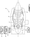
- FIG. 1 illustrates a gas turbine engine 10 (referred hereinafter as "engine 10") of a type preferably provided for use in subsonic flight, generally comprising in serial flow communication a fan 12 through which ambient air is propelled, a multistage compressor 14 for pressurizing the air, a combustor 16 in which the compressed air is mixed with fuel and ignited for generating an annular stream of hot combustion gases, and a turbine section 18 for extracting energy from the combustion gases.
- Engine 10 may include any type of engine suitable for use in aircraft applications.
- Engine 10 may include one or more keyed coupling systems 20 (referred hereinafter as "system 20") as described herein. Even though system 20 is illustrated and described in the context of engine 10, it is understood that system 20 may be used to establish torque transmission in various (e.g., aviation, automotive, marine, industrial) applications. In the exemplary embodiment illustrated in FIG. 1 , system 20 is used for torque transfer between motive power source 22 and oil pump 24, which may be part of a lubrication system of engine 10. Oil pump 24 may supply lubricating fluid to one or more lubrication loads 26 of engine 10 such as bearings and gears that require lubrication and/or cooling.
- lubrication loads 26 of engine 10 such as bearings and gears that require lubrication and/or cooling.
- Motive power source 22 may be drivingly engaged (e.g., in torque-transmitting engagement) with oil pump 24 via system 20.
- Sump 28 may be in fluid communication with lubrication load 26 and with oil pump 24 to collect oil from lubrication load 26 and return the oil to oil pump 24 for recirculation.
- Motive power source 22 may be an electric motor, hydraulic motor, pneumatic motor and/or a rotating/driven shaft of engine 10 drivingly coupled to oil pump 24 via an accessory gearbox and keyed coupling system 20 for example.
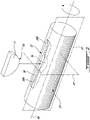
- FIG. 2 is a perspective view of an exemplary rotatable component (e.g., shaft 30) and key 31 which may be part of system 20.
- the rotatable component may be input shaft 30 of oil pump 24 that may be driven (i.e., receive an input torque) from motive power source 22 for example.
- Shaft 30 may be rotatable about rotation axis RA.
- Shaft 30 may include keyseat 32 formed therein.
- Keyseat 32 may include opening 34 defined in a radially-outer surface of shaft 30 for receiving a suitable key 31 therein.
- Keyseat 32 may include pocket 36 for mating engagement with part of the key received into keyseat 32.
- Keyseat 32 may include one or more axial keyseat extensions 38A, 38B that do not engage with key 31 during operation.
- First keyseat extension 38A may extend in a first axial direction from pocket 36 (and from key 31) relative to rotation axis RA of shaft 30.
- Second keyseat extension 38B may extend in a second axial direction opposite the first axial direction from pocket 36 (and from key 31) relative to rotation axis RA of shaft 30.
- keyseat 32 could instead be formed in a bore of a component (e.g., gear, pulley, wheel, coupler) that is mated and in torque-transmitting engagement with a shaft, and a cooperating keyway could instead be formed in the shaft.
- a component e.g., gear, pulley, wheel, coupler
- FIG. 3 is an axial cross-section view of part of an exemplary system 20.
- System 20 may include shaft 30 with keyseat 32 shown in FIG. 2 , key 31, and another rotatable component 42 that is in torque-transmitting engagement with shaft 30 via key 31.
- the cross-sectional view is taken in radial plane RP parallel to and containing rotation axis RA of shaft 30 and of component 42.
- Component 42 may include any device that is configured to induce rotary motion in, or have rotary motion induced by, shaft 30.
- component 42 may include another shaft, gear, pulley, wheel and/or coupler.
- Component 42 may include central bore 44 in which shaft 30 is received.
- Component 42 may include keyway 46 opening into central bore 44.
- key 31 may be a Woodruff key but it is understood that other types of keys may be suitable.
- key 31 may have an axial cross-sectional profile shaped as a circular segment as shown in FIGS. 2 and 3 .
- key 31 may have a semicircular axial cross-sectional profile.
- key 31 may have an axial cross-sectional profile shaped as an elliptical segment.
- Key 31 may have a thickness perpendicular to the page in FIG. 3 .
- the thickness of key 31 may be selected to provide the desired fit within keyseat 32 and keyway 46.
- the thickness of key 31 may be substantially uniform.
- the width of keyseat 32 perpendicular to the page in FIG. 3 may be substantially uniform.
- pocket, 36 and keyseat extensions 38A, 38B may have different or substantially identical (e.g., and uniform) widths. Keyseat extensions 38A, 38B may not be engaged with key 31.
- pocket 36 may have floor 48 having a curved axial cross-sectional profile that engages with and conforms to the shape of part (e.g., underside 50 in FIG. 2 ) of key 31 facing radially inwardly relative to rotation axis RA. Pocket 36 may also include sidewalls that engage with cooperating sidewalls of key 31.
- floor 48 of pocket 36 may have an arcuate axial cross-sectional profile having pocket radius R.
- the axial cross-sectional profile of floor 48 of pocket 36 may include a circular arc.
- the axial cross-sectional profile of floor 48 of pocket 36 may include part of an ellipse and/or part of an oval.
- underside 50 of key 31 may have a convex (e.g., fully or partially curved and/or multifaceted) axial cross-sectional profile
- floor 48 may have a cooperating (e.g., conforming) concave axial cross-sectional profile.
- keyseat 32 and key 31 may be substantially symmetric or asymmetric about axial plane AP that is normal to rotation axis RA.
- keyseat 32 may be dimensioned to provide desired structural performance and mitigate peak stresses in shaft 30 due to the presence of keyseat 32 in shaft 30. Dimensions of keyseat 32 for specific applications and load conditions may be determined empirically and/or via simulation and modelling using finite element analysis software for example.
- axial length W of keyseat 32 along rotation axis RA of shaft 30 may be equal to or greater than 1.33 times pocket radius R. In some embodiments, axial length W of keyseat 32 along rotation axis RA of shaft 30 may be about two times pocket radius R. In some embodiments, axial length W of keyseat 32 along rotation axis RA of shaft 30 may be between 1.33 and 10 times pocket radius R. In some embodiments, axial length W of keyseat 32 along rotation axis RA of shaft 30 may be between 1.33 and 5 times pocket radius R.
- the maximum depths from opening 34 of keyseat extensions 38A, 38B and of pocket 36 may also differ.
- pocket 36 may have a greater depth than those of keyseat extensions 38A, 38B so that when key 31 is seated into pocket 36, the cooperating mating surfaces of pocket 36 and key 31 may hinder or prevent relative axial movement between pocket 36 and key 31.
- a maximum depth H of pocket 36 may be greater than a maximum depth h of keyseat extension(s) 38A and/or 38B.
- maximum depths h of keyseat extensions 38A and 38B may differ from each other, or may be substantially identical.
- maximum depth h of keyseat extension(s) 38A and/or 38B may be between 0.5 times maximum depth H of pocket 36 and 0.8 times maximum depth H of pocket 36. In some embodiments, maximum depth h of keyseat extension(s) 38A and/or 38B may be about 2/3 of maximum depth H of pocket 36. The difference(s) in maximum depths H and h may result in keyseat 32 having a stepped floor.
- Axial cross-sectional profiles of keyseat extension(s) 38A, 38B may respectively define extension floors 52A, 52B and extension transitions 54A, 54B.
- Extension transitions 54A, 54B may provide respective geometric transitions between extension floors 52A, 52B and opening 34 formed in the surface of shaft 30.
- axial cross-sectional profiles of extension transitions 54A, 54B may each define a linear and planar ramp (e.g., chamfer) extending between extension floor 52A or 52B and opening 34.
- axial cross-sectional profiles of extension transitions 54A, 54B may be curved (e.g., arcuate).
- axial cross-sectional profiles of extension transitions 54A, 54B may include a circular arc and/or part of an ellipse or oval. In various embodiments, axial cross-sectional profiles of extension transitions 54A, 54B may differ from each other or may be substantially identical. In some embodiments, axial cross-sectional profiles of extension transitions 54A, 54B may have transition radius r. In some embodiments, transition radius r may be substantially identical to pocket radius R. In some embodiments, transition radius r may be greater than or smaller than pocket radius R. In some embodiments, transition radius r may have a non-zero value. In some embodiments, transition radius r may be two or more times pocket radius R.
- extension floors 52A, 52B may be substantially planar and substantially parallel to rotation axis RA.
- substantially tangent-continuous transitions may exist between extension transitions 54A, 54B and respective extension floors 52A, 52B.
- extension transitions 54A, 54B may define respective fillet transitions between extension floors 52A, 52B and opening 34.
- torque may be transmitted via key 31 either from shaft 30 to component 42 or from component 42 to shaft 30 as in the illustrated example of shaft 30 being an input shaft of oil pump 24.
- Key 31 may also serve as an overload fuse between shaft 30 and component 42 such that in the event of overloading, key 31 would fail (e.g., shear) prior to damage being caused to shaft 30 and/or component 42 during operation. Such failure of key 31 would cause torque transfer between shaft 30 and component 42 to be stopped.
- Woodruff keys One desirable property of using Woodruff keys is the ease of assembly and disassembly.
- the configuration of keyseat 32 may accomodate the use of Woodruff keys while retaining such desirable properties of using Woodruff keys.
- the stress maps depicted herein were generated using finite element analysis software using digital models of the applicable structures, and using a simulated unit (dummy) bending load in FIGS. 4A , 4B , and using a simulated unit (dummy) torsional load in FIGS. 5A , 5B .
- the configuration of keyseat 32 may, in some embodiments, promote a reduction in magnitude and relocation of peak (maximum principal) stresses on a component such as shaft 30 that includes keyseat 32 instead of baseline Woodruff keyseat 58.
- the stress maps depicted herein are examples under the operating conditions selected for illustration only. It is understood that the stress maps may be different for other operating conditions.
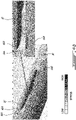
- FIG. 4A is a perspective view of a structural stress map around a baseline Woodruff keyseat 58 formed in baseline shaft 56 under an exemplary bending load.
- the bending load applied to baseline shaft 56 defines as a simply supported beam with a concentrated load applied at a mid span of the shaft where Woodruff keyseat 58 is located.
- the stress magnitudes displayed in the stress map may be compressive or tensile depending on whether baseline keyseat 58 is on the same side or one the opposite side of the applied bending load.
- An inset in FIG. 4A shows an enlarged portion of baseline keyseat 58.
- the stress map shows regions 60A, 60B of relatively low stress, and regions 62A, 62B of relatively high stress.
- FIG. 4B is a perspective view of a structural stress map around keyseat 32 of system 20 under the same bending load depicted in FIG. 4A for comparison.
- An inset in FIG. 4B shows an enlarged portion of keyseat 32.
- the stress map shows regions 64A, 64B of relatively low stress, and regions 66A, 66B of relatively high stress. Comparing FIGS. 4A and 4B reveals a dispersion and relocation of regions 62A, 62B of relatively high stress in baseline keyseat 58 to regions 66A, 66B of relatively high stress in keyseat 32.
- a comparison of the magnitudes of the highest peak stresses e.g., in regions 62A, 62B, 66A and 66B
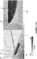
- FIG. 5A is a perspective view of a structural stress map around the baseline Woodruff keyseat 58 formed in baseline shaft 56 under a unit torsional load.
- An inset in FIG. 5A shows an enlarged portion of baseline keyseat 58.
- the stress map shows regions 68A, 68B of relatively low stress, and region 70A of relatively high stress.
- FIG. 5B is a perspective view of a structural stress map around keyseat 32 formed in shaft 30 under a unit torsional load.
- An inset in FIG. 5B shows an enlarged portion of keyseat 32.
- the stress map shows regions 72A, 72B of relatively low stress, and region 74A of relatively high stress. Comparing FIGS. 5A and 5B reveals a dispersion and relocation of regions 70A, of relatively high stress in baseline keyseat 58 to region 74A of relatively high stress in keyseat 32.
- the region of peak stress depicted as region 74A is now farther from the outer surface of shaft 30.
- a comparison of the magnitudes of the highest peak stresses has revealed a 26% reduction in magnitude of the maximum peak stresses.
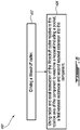
- FIGS. 6 and 7 illustrate an exemplary method 600 for forming keyseat 32 in shaft 30 or in another component.
- FIG. 6 is a flowchart of method 600 and FIG. 7 provides a graphical illustration of method 600 using Wodruff cutter 76.
- the same Woodruff cutter 76 may be used to machine the entirety of keyseat 32 in a single machining operation.
- different or other machining operations using different or other tools may be required.
- keyseat 32 may be formed in a metallic (e.g., steel) shaft 30 or other rotatable component by a suitable material removal process such as machining using a suitable (e.g., computer numerical control) machine tool for example.
- Method 600 may be used to machine keyseat 32 as depicted herein or other configurations of keyseat 32 into a component such as shaft 30. Accordingly, aspects of keyseat 32 and of system 20 described herein may be incorporated into method 600. The steps of method 600 are provided for illustrative purposes. Variations of the steps, omission or substitution of various steps, or additional steps may be considered. Method 600 may include:
- FIG. 7 schematically illustrates Woodruff cutter 76 and an exemplary toolpath 78 for machining keyseat 32 into shaft 30. It is understood that other types of toolpaths and cutters may be suitable. Shaft 30 and keyseat 32 are shown schematically in an axial cross-sectional view taken in radial plane RP. Tool path 78 may include one or more radial movements 78A and axial movements 78B that may be used during machining. In situations where pocket radius R and transition radius r (shown in FIG. 3 ) are substantially equal, Woodruff cutter 76 of a same outer radius may be selected to simplify toolpath 78. FIG.
- method 600 may use only a single tool (e.g., Woodruff cutter 76) to machine the entire keyseat 32. In some embodiments, method 600 may use a plurality of tools (e.g., side milling or other types of cutters) to machine the entire keyseat 32.
- a single tool e.g., Woodruff cutter 76
- a plurality of tools e.g., side milling or other types of cutters
Landscapes
- Engineering & Computer Science (AREA)
- General Engineering & Computer Science (AREA)
- Mechanical Engineering (AREA)
- Ocean & Marine Engineering (AREA)
- Shafts, Cranks, Connecting Bars, And Related Bearings (AREA)
- Chemical & Material Sciences (AREA)
- Combustion & Propulsion (AREA)
Abstract
Description
- The disclosure relates generally to keyed coupling systems for torque transmission, and more particularly to configurations of keyseats of keyed coupling systems.
- In machinery design, a key is an element that can be used to connect a rotating machine component to a shaft. The key is engaged with both the rotating machine component and the shaft to prevent relative rotation between the rotating machine component and the shaft to permit torque transmission. The shaft and the rotating machine component respectively include a keyseat (e.g., pocket) and a cooperating keyway (e.g., slot) in which the key is received in order to define a keyed joint between the shaft and the rotating machine component. Keyed joints can cause stress concentrations in the keyed components when a torque is transmitted between the components. The components must be sized in consideration of such stress concentrations. Improvement is desirable.
- In one aspect, the disclosure describes a Woodruff key coupling system for torque transmission. The system comprises:
- a Woodruff key;
- a rotatable shaft having a rotation axis, the shaft including a keyseat having a keyseat opening defined in an outer surface of the shaft, a first part of the Woodruff key being received in the keyseat via the keyseat opening, the keyseat including:
- a pocket engaged with the first part of the Woodruff key, the pocket having a maximum pocket depth relative to the keyseat opening;
- a first keyseat extension extending in a first axial direction from the Woodruff key relative to the rotation axis of the shaft, a maximum depth of the first keyseat extension relative to the keyseat opening being less than the maximum pocket depth; and
- a second keyseat extension extending in a second axial direction opposite the first axial direction from the Woodruff key relative to the rotation axis of the shaft, a maximum depth of the second keyseat extension relative to the keyseat opening being less than the maximum pocket depth; and
- a component in torque-transmitting engagement with the shaft, the component including a keyway, a second part of the Woodruff key being received in the keyway.
- In another aspect, the disclosure describes a rotatable component for keyed coupling with another component. The rotatable component has a rotation axis and comprises:
a keyseat having a keyseat opening for receiving a key therein, the keyseat including: - a pocket including a concave floor engageable with a part of the key, the floor having a curved axial cross-sectional profile relative to the rotation axis of the rotatable component;
- a first keyseat extension extending in a first axial direction from the pocket relative to the rotation axis of the rotatable component; and
- a second keyseat extension extending in a second axial direction opposite the first axial direction from the pocket relative to the rotation axis of the rotatable component.
- In a further aspect, the disclosure describes a method of forming a keyseat in a component having a rotation axis. The keyseat includes a pocket defining a circular segment engageable with part of a Woodruff key, a first keyseat extension extending in a first axial direction from the pocket relative to the rotation axis of the component, and a second keyseat extension extending in a second axial direction opposite the first axial direction from the pocket relative to the rotation axis of the component. The method comprises:
- driving a Woodruff cutter: and
- using radial and axial translation of the Woodruff cutter relative to the rotation axis of the component to machine the keyseat including the pocket, the first keyseat extension and the second keyseat extension into the component.
- Further details of these and other aspects of the subject matter of this application will be apparent from the detailed description included below and the drawings.
- Reference is now made to the accompanying drawings, in which:
-
FIG. 1 shows an axial cross-section view of an exemplary turbofan gas turbine engine including a keyed coupling system as described herein; -
FIG. 2 is a perspective view of a Woodruff key and a shaft defining an exemplary keyseat of the keyed coupling system ofFIG. 1 ; -
FIG. 3 is an axial cross-section view of an exemplary keyed coupling system including the keyseat ofFIG. 2 ; -
FIG. 4A is a structural stress map around a baseline keyseat formed in a shaft under a bending load; -
FIG. 4B is a structural stress map around the keyseat ofFIG. 2 formed in a shaft under the bending load; -
FIG. 5A is a structural stress map around the baseline keyseat ofFIG. 4A formed in the shaft under a torsional load; -
FIG. 5B is a structural stress map around the keyseat ofFIG. 2 formed in the shaft under the torsional load; -
FIG. 6 is a flowchart of a method of forming a keyseat in a component; and -
FIG. 7 is a schematic illustration of Woodruff cutter and an exemplary toolpath for machining the keyseat ofFIG. 2 into a shaft. - The present disclosure describes (e.g., Woodruff) keyed coupling systems to establish torque transmission between a first component (e.g., shaft) and a second component (e.g., shaft, gear, pulley, wheel, coupler). During torque transmission, keyed joints define a load path between the two components. The geometry and configuration of existing keyed joints can cause stress concentrations which may also be subjected to cyclic loading. Such stress concentrations may be caused by the presence of a keyseat in a shaft for example. The design of keyed joints must take into account peak stresses caused by such stress concentrations to properly size the components and obtain a suitable fatigue life under the applicable loading conditions.
- In some embodiments, the keyed coupling systems described herein may include configurations of keyseats that promote reduced peak stresses compared to other keyseat configurations. In some embodiments, the keyed coupling systems described herein may consequently promote reduced shaft size and weight, and/or improved fatigue life of components for example.
- In some embodiments, the configuration of keyseats described herein may be suitable for use with Woodruff keys. For example, the configuration of the keyseats described herein may retain the relatively simple installation and removal of Woodruff keys. In some embodiments, the keyseats described herein may be formed using a traditional Woodruff cutter.
- The terms "engaged with" and "coupled to" may include both direct engagement/coupling (in which two elements contact each other) and indirect engagement/coupling (in which at least one additional element is located between the two elements).
- The term "substantially" as used herein may be applied to modify any quantitative representation which could permissibly vary without resulting in a change in the basic function to which it is related.
- Aspects of various embodiments are described through reference to the drawings.
-
FIG. 1 illustrates a gas turbine engine 10 (referred hereinafter as "engine 10") of a type preferably provided for use in subsonic flight, generally comprising in serial flow communication afan 12 through which ambient air is propelled, amultistage compressor 14 for pressurizing the air, acombustor 16 in which the compressed air is mixed with fuel and ignited for generating an annular stream of hot combustion gases, and aturbine section 18 for extracting energy from the combustion gases.Engine 10 may include any type of engine suitable for use in aircraft applications. -
Engine 10 may include one or more keyed coupling systems 20 (referred hereinafter as "system 20") as described herein. Even thoughsystem 20 is illustrated and described in the context ofengine 10, it is understood thatsystem 20 may be used to establish torque transmission in various (e.g., aviation, automotive, marine, industrial) applications. In the exemplary embodiment illustrated inFIG. 1 ,system 20 is used for torque transfer betweenmotive power source 22 andoil pump 24, which may be part of a lubrication system ofengine 10.Oil pump 24 may supply lubricating fluid to one or more lubrication loads 26 ofengine 10 such as bearings and gears that require lubrication and/or cooling. -
Motive power source 22 may be drivingly engaged (e.g., in torque-transmitting engagement) withoil pump 24 viasystem 20.Sump 28 may be in fluid communication withlubrication load 26 and withoil pump 24 to collect oil fromlubrication load 26 and return the oil tooil pump 24 for recirculation.Motive power source 22 may be an electric motor, hydraulic motor, pneumatic motor and/or a rotating/driven shaft ofengine 10 drivingly coupled tooil pump 24 via an accessory gearbox and keyedcoupling system 20 for example. -
FIG. 2 is a perspective view of an exemplary rotatable component (e.g., shaft 30) and key 31 which may be part ofsystem 20. The rotatable component may beinput shaft 30 ofoil pump 24 that may be driven (i.e., receive an input torque) frommotive power source 22 for example.Shaft 30 may be rotatable about rotation axis RA.Shaft 30 may includekeyseat 32 formed therein.Keyseat 32 may include opening 34 defined in a radially-outer surface ofshaft 30 for receiving a suitable key 31 therein.Keyseat 32 may includepocket 36 for mating engagement with part of the key received intokeyseat 32.Keyseat 32 may include one or moreaxial keyseat extensions keyseat extension 38A may extend in a first axial direction from pocket 36 (and from key 31) relative to rotation axis RA ofshaft 30.Second keyseat extension 38B may extend in a second axial direction opposite the first axial direction from pocket 36 (and from key 31) relative to rotation axis RA ofshaft 30. - In some situations, keyseat 32 could instead be formed in a bore of a component (e.g., gear, pulley, wheel, coupler) that is mated and in torque-transmitting engagement with a shaft, and a cooperating keyway could instead be formed in the shaft.
-
FIG. 3 is an axial cross-section view of part of anexemplary system 20.System 20 may includeshaft 30 withkeyseat 32 shown inFIG. 2 , key 31, and anotherrotatable component 42 that is in torque-transmitting engagement withshaft 30 viakey 31. The cross-sectional view is taken in radial plane RP parallel to and containing rotation axis RA ofshaft 30 and ofcomponent 42.Component 42 may include any device that is configured to induce rotary motion in, or have rotary motion induced by,shaft 30. As non-limiting examples,component 42 may include another shaft, gear, pulley, wheel and/or coupler. -
Component 42 may includecentral bore 44 in whichshaft 30 is received.Component 42 may includekeyway 46 opening intocentral bore 44. Whenshaft 30 andcomponent 42 are assembled together in a torque-transmitting engagement,upper part 31A of key 31 may be received into and engaged withkeyway 46 formed incomponent 42, andlower part 31B of key 31 may be received into and engaged with (e.g., pocket 36) ofkeyseat 32 formed inshaft 30. - In some embodiments, key 31 may be a Woodruff key but it is understood that other types of keys may be suitable. For example, key 31 may have an axial cross-sectional profile shaped as a circular segment as shown in
FIGS. 2 and3 . In some embodiments, key 31 may have a semicircular axial cross-sectional profile. In some embodiments, key 31 may have an axial cross-sectional profile shaped as an elliptical segment.Key 31 may have a thickness perpendicular to the page inFIG. 3 . The thickness ofkey 31 may be selected to provide the desired fit withinkeyseat 32 andkeyway 46. In some embodiments, the thickness ofkey 31 may be substantially uniform. In some embodiments, the width ofkeyseat 32 perpendicular to the page inFIG. 3 may be substantially uniform. In various embodiments pocket, 36 andkeyseat extensions Keyseat extensions key 31. - In some embodiments,
pocket 36 may havefloor 48 having a curved axial cross-sectional profile that engages with and conforms to the shape of part (e.g.,underside 50 inFIG. 2 ) ofkey 31 facing radially inwardly relative to rotation axis RA.Pocket 36 may also include sidewalls that engage with cooperating sidewalls ofkey 31. In some embodiments,floor 48 ofpocket 36 may have an arcuate axial cross-sectional profile having pocket radius R. In some embodiments, the axial cross-sectional profile offloor 48 ofpocket 36 may include a circular arc. In some embodiments, the axial cross-sectional profile offloor 48 ofpocket 36 may include part of an ellipse and/or part of an oval. It is understood that other types of curvatures offloor 48 and of key 31 may be suitable. For example,underside 50 ofkey 31 may have a convex (e.g., fully or partially curved and/or multifaceted) axial cross-sectional profile, andfloor 48 may have a cooperating (e.g., conforming) concave axial cross-sectional profile. In some embodiments,keyseat 32 and key 31 may be substantially symmetric or asymmetric about axial plane AP that is normal to rotation axis RA. - Features of
keyseat 32 may be dimensioned to provide desired structural performance and mitigate peak stresses inshaft 30 due to the presence ofkeyseat 32 inshaft 30. Dimensions ofkeyseat 32 for specific applications and load conditions may be determined empirically and/or via simulation and modelling using finite element analysis software for example. In some embodiments, axial length W ofkeyseat 32 along rotation axis RA ofshaft 30 may be equal to or greater than 1.33 times pocket radius R. In some embodiments, axial length W ofkeyseat 32 along rotation axis RA ofshaft 30 may be about two times pocket radius R. In some embodiments, axial length W ofkeyseat 32 along rotation axis RA ofshaft 30 may be between 1.33 and 10 times pocket radius R. In some embodiments, axial length W ofkeyseat 32 along rotation axis RA ofshaft 30 may be between 1.33 and 5 times pocket radius R. - The maximum depths from opening 34 of
keyseat extensions pocket 36 may also differ. For example,pocket 36 may have a greater depth than those ofkeyseat extensions pocket 36, the cooperating mating surfaces ofpocket 36 and key 31 may hinder or prevent relative axial movement betweenpocket 36 and key 31. In reference toFIG. 3 , a maximum depth H ofpocket 36 may be greater than a maximum depth h of keyseat extension(s) 38A and/or 38B. In some embodiments, maximum depths h ofkeyseat extensions pocket 36 and 0.8 times maximum depth H ofpocket 36. In some embodiments, maximum depth h of keyseat extension(s) 38A and/or 38B may be about 2/3 of maximum depth H ofpocket 36. The difference(s) in maximum depths H and h may result inkeyseat 32 having a stepped floor. - Axial cross-sectional profiles of keyseat extension(s) 38A, 38B may respectively define
extension floors extension floors opening 34 formed in the surface ofshaft 30. In some embodiments, axial cross-sectional profiles of extension transitions 54A, 54B may each define a linear and planar ramp (e.g., chamfer) extending betweenextension floor opening 34. In some embodiments, axial cross-sectional profiles of extension transitions 54A, 54B may be curved (e.g., arcuate). In some embodiments, axial cross-sectional profiles of extension transitions 54A, 54B may include a circular arc and/or part of an ellipse or oval. In various embodiments, axial cross-sectional profiles of extension transitions 54A, 54B may differ from each other or may be substantially identical. In some embodiments, axial cross-sectional profiles of extension transitions 54A, 54B may have transition radius r. In some embodiments, transition radius r may be substantially identical to pocket radius R. In some embodiments, transition radius r may be greater than or smaller than pocket radius R. In some embodiments, transition radius r may have a non-zero value. In some embodiments, transition radius r may be two or more times pocket radius R. - In some embodiments,
extension floors respective extension floors extension floors opening 34. - During operation of
system 20, torque may be transmitted viakey 31 either fromshaft 30 tocomponent 42 or fromcomponent 42 toshaft 30 as in the illustrated example ofshaft 30 being an input shaft ofoil pump 24.Key 31 may also serve as an overload fuse betweenshaft 30 andcomponent 42 such that in the event of overloading, key 31 would fail (e.g., shear) prior to damage being caused toshaft 30 and/orcomponent 42 during operation. Such failure of key 31 would cause torque transfer betweenshaft 30 andcomponent 42 to be stopped. - One desirable property of using Woodruff keys is the ease of assembly and disassembly. In some embodiments, the configuration of
keyseat 32 may accomodate the use of Woodruff keys while retaining such desirable properties of using Woodruff keys. - In reference to
FIGS. 4A ,4B ,5A and5B , the stress maps depicted herein were generated using finite element analysis software using digital models of the applicable structures, and using a simulated unit (dummy) bending load inFIGS. 4A ,4B , and using a simulated unit (dummy) torsional load inFIGS. 5A ,5B . As explained below, experiments have revealed that the configuration ofkeyseat 32 may, in some embodiments, promote a reduction in magnitude and relocation of peak (maximum principal) stresses on a component such asshaft 30 that includeskeyseat 32 instead ofbaseline Woodruff keyseat 58. The stress maps depicted herein are examples under the operating conditions selected for illustration only. It is understood that the stress maps may be different for other operating conditions. -
FIG. 4A is a perspective view of a structural stress map around a baseline Woodruff keyseat 58 formed inbaseline shaft 56 under an exemplary bending load. The bending load applied tobaseline shaft 56 defines as a simply supported beam with a concentrated load applied at a mid span of the shaft where Woodruff keyseat 58 is located. The stress magnitudes displayed in the stress map may be compressive or tensile depending on whether baseline keyseat 58 is on the same side or one the opposite side of the applied bending load. An inset inFIG. 4A shows an enlarged portion ofbaseline keyseat 58. The stress map showsregions regions -
FIG. 4B is a perspective view of a structural stress map aroundkeyseat 32 ofsystem 20 under the same bending load depicted inFIG. 4A for comparison. An inset inFIG. 4B shows an enlarged portion ofkeyseat 32. The stress map showsregions regions FIGS. 4A and4B reveals a dispersion and relocation ofregions regions keyseat 32. For the specific unit bending loading depicted inFIGS. 4A and4B as an example, a comparison of the magnitudes of the highest peak stresses (e.g., inregions -
FIG. 5A is a perspective view of a structural stress map around the baseline Woodruff keyseat 58 formed inbaseline shaft 56 under a unit torsional load. An inset inFIG. 5A shows an enlarged portion ofbaseline keyseat 58. The stress map showsregions region 70A of relatively high stress. -
FIG. 5B is a perspective view of a structural stress map aroundkeyseat 32 formed inshaft 30 under a unit torsional load. An inset inFIG. 5B shows an enlarged portion ofkeyseat 32. The stress map showsregions region 74A of relatively high stress. ComparingFIGS. 5A and5B reveals a dispersion and relocation ofregions 70A, of relatively high stress in baseline keyseat 58 toregion 74A of relatively high stress inkeyseat 32. For example, the region of peak stress depicted asregion 74A is now farther from the outer surface ofshaft 30. For the specific unit torsional loading depicted inFIGS. 5A and5B as an example, a comparison of the magnitudes of the highest peak stresses (e.g., inregions -
FIGS. 6 and7 illustrate anexemplary method 600 for formingkeyseat 32 inshaft 30 or in another component.FIG. 6 is a flowchart ofmethod 600 andFIG. 7 provides a graphical illustration ofmethod 600 usingWodruff cutter 76. In some embodiments ofkeyseat 32, thesame Woodruff cutter 76 may be used to machine the entirety ofkeyseat 32 in a single machining operation. In some embodiments ofkeyseat 32, different or other machining operations using different or other tools may be required. In some embodiments, keyseat 32 may be formed in a metallic (e.g., steel)shaft 30 or other rotatable component by a suitable material removal process such as machining using a suitable (e.g., computer numerical control) machine tool for example. -
Method 600 may be used tomachine keyseat 32 as depicted herein or other configurations ofkeyseat 32 into a component such asshaft 30. Accordingly, aspects ofkeyseat 32 and ofsystem 20 described herein may be incorporated intomethod 600. The steps ofmethod 600 are provided for illustrative purposes. Variations of the steps, omission or substitution of various steps, or additional steps may be considered.Method 600 may include: - driving (i.e., rotating) a Woodruff cutter 76 (see block 602); and
- using radial and axial translation of the
Woodruff cutter 76 relative to rotation axis RA tomachine keyseat 32 includingpocket 36,first keyseat extension 38A andsecond keyseat extension 38B (see block 604). -
FIG. 7 schematically illustratesWoodruff cutter 76 and anexemplary toolpath 78 for machiningkeyseat 32 intoshaft 30. It is understood that other types of toolpaths and cutters may be suitable.Shaft 30 andkeyseat 32 are shown schematically in an axial cross-sectional view taken in radial plane RP.Tool path 78 may include one or moreradial movements 78A andaxial movements 78B that may be used during machining. In situations where pocket radius R and transition radius r (shown inFIG. 3 ) are substantially equal,Woodruff cutter 76 of a same outer radius may be selected to simplifytoolpath 78.FIG. 7 shows toolpath 78 for a single (e.g., final) machining pass but it is understood that multiple machining passes at different depths may be used in some embodiments. In some embodiments,method 600 may use only a single tool (e.g., Woodruff cutter 76) to machine theentire keyseat 32. In some embodiments,method 600 may use a plurality of tools (e.g., side milling or other types of cutters) to machine theentire keyseat 32. - The embodiments described in this document provide non-limiting examples of possible implementations of the present technology. Upon review of the present disclosure, a person of ordinary skill in the art will recognize that changes may be made to the embodiments described herein without departing from the scope of the present technology. Further modifications could be implemented by a person of ordinary skill in the art in view of the present disclosure, which modifications would be within the scope of the present technology.
Claims (15)
- A Woodruff key coupling system (20) for torque transmission, the system (20) comprising:a Woodruff key (31);a rotatable shaft (30) having a rotation axis (RA), the shaft (30) including a keyseat (32) having a keyseat opening (34) defined in an outer surface of the shaft (30), a first part of the Woodruff key (31) being received in the keyseat (32) via the keyseat opening (34), the keyseat (32) including:a pocket (36) engaged with the first part of the Woodruff key (31), the pocket (36) having a maximum pocket depth (H) relative to the keyseat opening (34);a first keyseat extension (38A) extending in a first axial direction from the Woodruff key (31) relative to the rotation axis (RA) of the shaft (30), a maximum depth of the first keyseat extension (38A) relative to the keyseat opening (34) being less than the maximum pocket depth (H); anda second keyseat extension (38B) extending in a second axial direction opposite the first axial direction from the Woodruff key (31) relative to the rotation axis (RA) of the shaft (30), a maximum depth (h) of the second keyseat extension (38B) relative to the keyseat opening (34) being less than the maximum pocket depth (H); anda component (42) in torque-transmitting engagement with the shaft (30), the component (42) including a keyway (46), a second part of the Woodruff key (31A) being received in the keyway (46).
- The system (20) of claim 1, wherein:a floor (48) of the pocket (36) has an arcuate axial cross-sectional profile having a pocket radius (R);an axial length (W) of the keyseat (32) along the rotation axis (RA) of the shaft (30) is equal to or greater than 1.33 times the pocket radius (R).
- The system (20) of claim 2, wherein the axial length (W) of the keyseat (32) is about two times the pocket radius (R).
- The system (20) of claim 1, wherein:a floor (48) of the pocket (36) has an arcuate axial cross-sectional profile; andan axial cross-sectional profile of the first keyseat extension (38A) defines an arcuate transition (54A) between the keyseat opening (34) and a floor (52A) of the first keyseat extension (38A).
- The system (20) of claim 4, wherein:the arcuate axial cross-sectional profile of the floor (48) of the pocket (36) has a pocket radius (R); andthe arcuate transition (54A) has a transition radius (r) substantially equal to the pocket radius (R).
- The system (20) of any preceding claim, wherein the maximum depth (h) of the first keyseat extension (38A) is between 0.5 times the maximum pocket depth (H) and 0.8 times the maximum pocket depth (H), and/or wherein the maximum depth (h) of the second keyseat extension (38B) is between 0.5 times the maximum pocket depth (H) and 0.8 times the maximum pocket depth (H).
- The system (20) of any preceding claim, wherein the maximum depth (h) of the first keyseat extension (38A) is about 2/3 of the maximum pocket depth (H), and/or wherein the maximum depth (h) of the second keyseat extension (38B) is about 2/3 of the maximum pocket depth (H).
- A rotatable component (30) for keyed coupling with another component (42), the rotatable component (30) having a rotation axis (RA) and comprising:
a keyseat (32) having a keyseat opening (34) for receiving a key (31) therein, the keyseat (32) including:a pocket (36) including a concave floor (48) engageable with a part of the key (31), the floor (48) having a curved axial cross-sectional profile relative to the rotation axis (RA) of the rotatable component (30);a first keyseat extension (38A) extending in a first axial direction from the pocket (36) relative to the rotation axis (RA) of the rotatable component (30); anda second keyseat extension (38B) extending in a second axial direction opposite the first axial direction from the pocket (36) relative to the rotation axis (RA) of the rotatable component (30). - The rotatable component (30) of claim 8, wherein the rotatable component (30) is a shaft (30) of an oil pump (24) of a gas turbine engine (10).
- The rotatable component (30) of claim 8 or 9, wherein the curved axial cross-sectional profile of the concave floor (48) includes an arc and, optionally, wherein:the arc has a radius (R);an axial length (W) of the keyseat opening (34) is equal to or greater than 1.33 times the radius (R).
- The rotatable component (30) of claim 8, 9 or 10, wherein:the pocket (36) has a maximum pocket depth (H) relative to the keyseat opening (34);a maximum depth (h) of the first keyseat extension (38A) relative to the keyseat opening (34) is less than the maximum pocket depth (H); anda maximum depth (h) of the second keyseat extension (38B) relative to the keyseat opening (34) is less than the maximum pocket depth (H),wherein, optionally, the maximum depth (h) of the first keyseat extension (38A) is between 0.5 times the maximum pocket depth (H) and 0.8 times the maximum pocket depth (H).
- The rotatable component (30) of any of claims 8 to 11, wherein an axial cross-sectional profile of the first keyseat extension (38A) defines a curved transition (54A) between the keyseat opening (34) and a floor (52A) of the first keyseat extension (38A).
- The rotatable component (30) of claim 12, wherein:the curved axial cross-sectional profile of the concave floor (48) of the pocket (36) includes a first or the arc; andthe curved transition (54A) between the keyseat opening (34) and the floor (52A) of the first keyseat extension (38A) includes a second arc.
- A method of forming a keyseat (32) in a component (30) having a rotation axis (RA), the keyseat (32) including a pocket (36) defining a circular segment engageable with part of a Woodruff key (31), a first keyseat extension (38A) extending in a first axial direction from the pocket (36) relative to the rotation axis (RA) of the component (30), and a second keyseat extension (38B) extending in a second axial direction opposite the first axial direction from the pocket (36) relative to the rotation axis (RA) of the component (30), the method comprising:driving a Woodruff cutter (76): andusing radial and axial translation of the Woodruff cutter (76) relative to the rotation axis (RA) of the component (30) to machine the keyseat (32) including the pocket (36), the first keyseat extension (38A) and the second keyseat extension (38B) into the component (30).
- The method of claim 14, wherein the pocket (36) and the first keyseat extension (38A) have different depths (H, h).
Applications Claiming Priority (1)
| Application Number | Priority Date | Filing Date | Title |
|---|---|---|---|
| US17/186,210 US11927223B2 (en) | 2021-02-26 | 2021-02-26 | Keyed coupling system for torque transmission |
Publications (2)
| Publication Number | Publication Date |
|---|---|
| EP4050229A1 true EP4050229A1 (en) | 2022-08-31 |
| EP4050229B1 EP4050229B1 (en) | 2023-12-20 |
Family
ID=80461064
Family Applications (1)
| Application Number | Title | Priority Date | Filing Date |
|---|---|---|---|
| EP22158627.4A Active EP4050229B1 (en) | 2021-02-26 | 2022-02-24 | Keyed coupling system for torque transmission |
Country Status (3)
| Country | Link |
|---|---|
| US (1) | US11927223B2 (en) |
| EP (1) | EP4050229B1 (en) |
| CA (1) | CA3150214A1 (en) |
Citations (2)
| Publication number | Priority date | Publication date | Assignee | Title |
|---|---|---|---|---|
| GB393473A (en) * | 1932-10-25 | 1933-06-08 | John Robert Johnson | Improvements in or relating to mechanical keying means |
| US2563166A (en) * | 1947-07-03 | 1951-08-07 | Jack I Gardner | Locking means for shaft keys |
Family Cites Families (8)
| Publication number | Priority date | Publication date | Assignee | Title |
|---|---|---|---|---|
| US368744A (en) | 1887-08-23 | Shaft-key | ||
| US921401A (en) * | 1907-06-26 | 1909-05-11 | Henry J Hjorth | Self-fitting key. |
| US1221709A (en) * | 1914-08-14 | 1917-04-03 | Frank J Dyett | Key. |
| FR1025383A (en) * | 1950-10-02 | 1953-04-14 | Improvements to semi-circular keys | |
| US2973979A (en) * | 1958-02-26 | 1961-03-07 | Musser C Walton | Key |
| GB1429423A (en) * | 1973-08-03 | 1976-03-24 | Gen Signal Corp | Lokcing key |
| DE19649034C1 (en) * | 1996-11-27 | 1998-02-26 | Ford Werke Ag | Disc spring for insertion in groove in shaft |
| US20160061249A1 (en) | 2014-08-29 | 2016-03-03 | Douglas H. Powell | Adjustable shear key |
-
2021
- 2021-02-26 US US17/186,210 patent/US11927223B2/en active Active
-
2022
- 2022-02-24 EP EP22158627.4A patent/EP4050229B1/en active Active
- 2022-02-25 CA CA3150214A patent/CA3150214A1/en active Pending
Patent Citations (2)
| Publication number | Priority date | Publication date | Assignee | Title |
|---|---|---|---|---|
| GB393473A (en) * | 1932-10-25 | 1933-06-08 | John Robert Johnson | Improvements in or relating to mechanical keying means |
| US2563166A (en) * | 1947-07-03 | 1951-08-07 | Jack I Gardner | Locking means for shaft keys |
Also Published As
| Publication number | Publication date |
|---|---|
| EP4050229B1 (en) | 2023-12-20 |
| US20220275837A1 (en) | 2022-09-01 |
| CA3150214A1 (en) | 2022-08-26 |
| US11927223B2 (en) | 2024-03-12 |
Similar Documents
| Publication | Publication Date | Title |
|---|---|---|
| US11346285B2 (en) | Compact accessory systems for a gas turbine engine | |
| US8465373B2 (en) | Face coupling | |
| EP3869064B1 (en) | Planetary gearbox having compliant journal bearings | |
| EP2199573B1 (en) | Generator coupling for use with gas turbine engine | |
| EP2481880A2 (en) | Drive shaft constant velocity joint assembly with radial elliptical projections | |
| US8613609B2 (en) | Bi-metal pump gear | |
| EP4050229B1 (en) | Keyed coupling system for torque transmission | |
| US20230417153A1 (en) | Lubricant pump system and method for aircraft engine | |
| EP3421171B1 (en) | Turbine wheels, turbine engines including the same, and methods of fabricating turbine wheels with improved bond line geometry | |
| US9682756B1 (en) | System for composite marine propellers | |
| Vishwakarma et al. | Effect of tapered interference fit between impeller and shaft in turbo machines | |
| Mancuso et al. | Coupling Interface Connection. | |
| EP4403750A1 (en) | Mounting system for gearbox including corrugated bushing | |
| US12180969B2 (en) | Centrifugal compressor | |
| EP2546493B1 (en) | Contained shaft spring load | |
| US11603890B2 (en) | Driveline engagement system | |
| EP3450072A1 (en) | Entrance and exit chip rings for balancing broach forces | |
| Arafa | Elastic Deformation and Microslip Issues | |
| Doidge | Drivetrain Protection through Coupling Design | |
| JP2025533883A (en) | Adapter for torque transmission between two rotatable components | |
| Tian | Selection and Comparative Study of Mechanical Fitting Processes: With a Focus on the Application of Motor Rotor Shaft and Rotor Stack Fitting | |
| Radzevich | The Kinds and Causes of Gear Failures | |
| CA3085822C (en) | Shaft assembly for an aircraft turbomachine | |
| Karassik et al. | Couplings | |
| Patil | Performance Evaluation and Analysis of Three Pin Constant Velocity Joint |
Legal Events
| Date | Code | Title | Description |
|---|---|---|---|
| PUAI | Public reference made under article 153(3) epc to a published international application that has entered the european phase |
Free format text: ORIGINAL CODE: 0009012 |
|
| STAA | Information on the status of an ep patent application or granted ep patent |
Free format text: STATUS: THE APPLICATION HAS BEEN PUBLISHED |
|
| AK | Designated contracting states |
Kind code of ref document: A1 Designated state(s): AL AT BE BG CH CY CZ DE DK EE ES FI FR GB GR HR HU IE IS IT LI LT LU LV MC MK MT NL NO PL PT RO RS SE SI SK SM TR |
|
| STAA | Information on the status of an ep patent application or granted ep patent |
Free format text: STATUS: REQUEST FOR EXAMINATION WAS MADE |
|
| 17P | Request for examination filed |
Effective date: 20230228 |
|
| RBV | Designated contracting states (corrected) |
Designated state(s): AL AT BE BG CH CY CZ DE DK EE ES FI FR GB GR HR HU IE IS IT LI LT LU LV MC MK MT NL NO PL PT RO RS SE SI SK SM TR |
|
| GRAP | Despatch of communication of intention to grant a patent |
Free format text: ORIGINAL CODE: EPIDOSNIGR1 |
|
| STAA | Information on the status of an ep patent application or granted ep patent |
Free format text: STATUS: GRANT OF PATENT IS INTENDED |
|
| INTG | Intention to grant announced |
Effective date: 20230630 |
|
| GRAS | Grant fee paid |
Free format text: ORIGINAL CODE: EPIDOSNIGR3 |
|
| GRAA | (expected) grant |
Free format text: ORIGINAL CODE: 0009210 |
|
| STAA | Information on the status of an ep patent application or granted ep patent |
Free format text: STATUS: THE PATENT HAS BEEN GRANTED |
|
| AK | Designated contracting states |
Kind code of ref document: B1 Designated state(s): AL AT BE BG CH CY CZ DE DK EE ES FI FR GB GR HR HU IE IS IT LI LT LU LV MC MK MT NL NO PL PT RO RS SE SI SK SM TR |
|
| REG | Reference to a national code |
Ref country code: GB Ref legal event code: FG4D |
|
| REG | Reference to a national code |
Ref country code: DE Ref legal event code: R096 Ref document number: 602022001325 Country of ref document: DE |
|
| REG | Reference to a national code |
Ref country code: CH Ref legal event code: EP |
|
| REG | Reference to a national code |
Ref country code: IE Ref legal event code: FG4D |
|
| PG25 | Lapsed in a contracting state [announced via postgrant information from national office to epo] |
Ref country code: GR Free format text: LAPSE BECAUSE OF FAILURE TO SUBMIT A TRANSLATION OF THE DESCRIPTION OR TO PAY THE FEE WITHIN THE PRESCRIBED TIME-LIMIT Effective date: 20240321 |
|
| REG | Reference to a national code |
Ref country code: LT Ref legal event code: MG9D |
|
| PG25 | Lapsed in a contracting state [announced via postgrant information from national office to epo] |
Ref country code: LT Free format text: LAPSE BECAUSE OF FAILURE TO SUBMIT A TRANSLATION OF THE DESCRIPTION OR TO PAY THE FEE WITHIN THE PRESCRIBED TIME-LIMIT Effective date: 20231220 |
|
| REG | Reference to a national code |
Ref country code: NL Ref legal event code: MP Effective date: 20231220 |
|
| PG25 | Lapsed in a contracting state [announced via postgrant information from national office to epo] |
Ref country code: ES Free format text: LAPSE BECAUSE OF FAILURE TO SUBMIT A TRANSLATION OF THE DESCRIPTION OR TO PAY THE FEE WITHIN THE PRESCRIBED TIME-LIMIT Effective date: 20231220 |
|
| PG25 | Lapsed in a contracting state [announced via postgrant information from national office to epo] |
Ref country code: LT Free format text: LAPSE BECAUSE OF FAILURE TO SUBMIT A TRANSLATION OF THE DESCRIPTION OR TO PAY THE FEE WITHIN THE PRESCRIBED TIME-LIMIT Effective date: 20231220 Ref country code: GR Free format text: LAPSE BECAUSE OF FAILURE TO SUBMIT A TRANSLATION OF THE DESCRIPTION OR TO PAY THE FEE WITHIN THE PRESCRIBED TIME-LIMIT Effective date: 20240321 Ref country code: FI Free format text: LAPSE BECAUSE OF FAILURE TO SUBMIT A TRANSLATION OF THE DESCRIPTION OR TO PAY THE FEE WITHIN THE PRESCRIBED TIME-LIMIT Effective date: 20231220 Ref country code: ES Free format text: LAPSE BECAUSE OF FAILURE TO SUBMIT A TRANSLATION OF THE DESCRIPTION OR TO PAY THE FEE WITHIN THE PRESCRIBED TIME-LIMIT Effective date: 20231220 Ref country code: BG Free format text: LAPSE BECAUSE OF FAILURE TO SUBMIT A TRANSLATION OF THE DESCRIPTION OR TO PAY THE FEE WITHIN THE PRESCRIBED TIME-LIMIT Effective date: 20240320 |
|
| REG | Reference to a national code |
Ref country code: AT Ref legal event code: MK05 Ref document number: 1642697 Country of ref document: AT Kind code of ref document: T Effective date: 20231220 |
|
| PG25 | Lapsed in a contracting state [announced via postgrant information from national office to epo] |
Ref country code: NL Free format text: LAPSE BECAUSE OF FAILURE TO SUBMIT A TRANSLATION OF THE DESCRIPTION OR TO PAY THE FEE WITHIN THE PRESCRIBED TIME-LIMIT Effective date: 20231220 |
|
| PG25 | Lapsed in a contracting state [announced via postgrant information from national office to epo] |
Ref country code: SE Free format text: LAPSE BECAUSE OF FAILURE TO SUBMIT A TRANSLATION OF THE DESCRIPTION OR TO PAY THE FEE WITHIN THE PRESCRIBED TIME-LIMIT Effective date: 20231220 Ref country code: RS Free format text: LAPSE BECAUSE OF FAILURE TO SUBMIT A TRANSLATION OF THE DESCRIPTION OR TO PAY THE FEE WITHIN THE PRESCRIBED TIME-LIMIT Effective date: 20231220 Ref country code: NO Free format text: LAPSE BECAUSE OF FAILURE TO SUBMIT A TRANSLATION OF THE DESCRIPTION OR TO PAY THE FEE WITHIN THE PRESCRIBED TIME-LIMIT Effective date: 20240320 Ref country code: NL Free format text: LAPSE BECAUSE OF FAILURE TO SUBMIT A TRANSLATION OF THE DESCRIPTION OR TO PAY THE FEE WITHIN THE PRESCRIBED TIME-LIMIT Effective date: 20231220 Ref country code: LV Free format text: LAPSE BECAUSE OF FAILURE TO SUBMIT A TRANSLATION OF THE DESCRIPTION OR TO PAY THE FEE WITHIN THE PRESCRIBED TIME-LIMIT Effective date: 20231220 Ref country code: HR Free format text: LAPSE BECAUSE OF FAILURE TO SUBMIT A TRANSLATION OF THE DESCRIPTION OR TO PAY THE FEE WITHIN THE PRESCRIBED TIME-LIMIT Effective date: 20231220 |
|
| PG25 | Lapsed in a contracting state [announced via postgrant information from national office to epo] |
Ref country code: IS Free format text: LAPSE BECAUSE OF FAILURE TO SUBMIT A TRANSLATION OF THE DESCRIPTION OR TO PAY THE FEE WITHIN THE PRESCRIBED TIME-LIMIT Effective date: 20240420 |
|
| PG25 | Lapsed in a contracting state [announced via postgrant information from national office to epo] |
Ref country code: CZ Free format text: LAPSE BECAUSE OF FAILURE TO SUBMIT A TRANSLATION OF THE DESCRIPTION OR TO PAY THE FEE WITHIN THE PRESCRIBED TIME-LIMIT Effective date: 20231220 Ref country code: AT Free format text: LAPSE BECAUSE OF FAILURE TO SUBMIT A TRANSLATION OF THE DESCRIPTION OR TO PAY THE FEE WITHIN THE PRESCRIBED TIME-LIMIT Effective date: 20231220 |
|
| PG25 | Lapsed in a contracting state [announced via postgrant information from national office to epo] |
Ref country code: SK Free format text: LAPSE BECAUSE OF FAILURE TO SUBMIT A TRANSLATION OF THE DESCRIPTION OR TO PAY THE FEE WITHIN THE PRESCRIBED TIME-LIMIT Effective date: 20231220 |
|
| PG25 | Lapsed in a contracting state [announced via postgrant information from national office to epo] |
Ref country code: SM Free format text: LAPSE BECAUSE OF FAILURE TO SUBMIT A TRANSLATION OF THE DESCRIPTION OR TO PAY THE FEE WITHIN THE PRESCRIBED TIME-LIMIT Effective date: 20231220 Ref country code: SK Free format text: LAPSE BECAUSE OF FAILURE TO SUBMIT A TRANSLATION OF THE DESCRIPTION OR TO PAY THE FEE WITHIN THE PRESCRIBED TIME-LIMIT Effective date: 20231220 Ref country code: RO Free format text: LAPSE BECAUSE OF FAILURE TO SUBMIT A TRANSLATION OF THE DESCRIPTION OR TO PAY THE FEE WITHIN THE PRESCRIBED TIME-LIMIT Effective date: 20231220 Ref country code: IT Free format text: LAPSE BECAUSE OF FAILURE TO SUBMIT A TRANSLATION OF THE DESCRIPTION OR TO PAY THE FEE WITHIN THE PRESCRIBED TIME-LIMIT Effective date: 20231220 Ref country code: IS Free format text: LAPSE BECAUSE OF FAILURE TO SUBMIT A TRANSLATION OF THE DESCRIPTION OR TO PAY THE FEE WITHIN THE PRESCRIBED TIME-LIMIT Effective date: 20240420 Ref country code: EE Free format text: LAPSE BECAUSE OF FAILURE TO SUBMIT A TRANSLATION OF THE DESCRIPTION OR TO PAY THE FEE WITHIN THE PRESCRIBED TIME-LIMIT Effective date: 20231220 Ref country code: CZ Free format text: LAPSE BECAUSE OF FAILURE TO SUBMIT A TRANSLATION OF THE DESCRIPTION OR TO PAY THE FEE WITHIN THE PRESCRIBED TIME-LIMIT Effective date: 20231220 Ref country code: AT Free format text: LAPSE BECAUSE OF FAILURE TO SUBMIT A TRANSLATION OF THE DESCRIPTION OR TO PAY THE FEE WITHIN THE PRESCRIBED TIME-LIMIT Effective date: 20231220 |
|
| PG25 | Lapsed in a contracting state [announced via postgrant information from national office to epo] |
Ref country code: PL Free format text: LAPSE BECAUSE OF FAILURE TO SUBMIT A TRANSLATION OF THE DESCRIPTION OR TO PAY THE FEE WITHIN THE PRESCRIBED TIME-LIMIT Effective date: 20231220 Ref country code: PT Free format text: LAPSE BECAUSE OF FAILURE TO SUBMIT A TRANSLATION OF THE DESCRIPTION OR TO PAY THE FEE WITHIN THE PRESCRIBED TIME-LIMIT Effective date: 20240422 |
|
| PG25 | Lapsed in a contracting state [announced via postgrant information from national office to epo] |
Ref country code: PT Free format text: LAPSE BECAUSE OF FAILURE TO SUBMIT A TRANSLATION OF THE DESCRIPTION OR TO PAY THE FEE WITHIN THE PRESCRIBED TIME-LIMIT Effective date: 20240422 Ref country code: PL Free format text: LAPSE BECAUSE OF FAILURE TO SUBMIT A TRANSLATION OF THE DESCRIPTION OR TO PAY THE FEE WITHIN THE PRESCRIBED TIME-LIMIT Effective date: 20231220 |
|
| REG | Reference to a national code |
Ref country code: DE Ref legal event code: R097 Ref document number: 602022001325 Country of ref document: DE |
|
| PG25 | Lapsed in a contracting state [announced via postgrant information from national office to epo] |
Ref country code: MC Free format text: LAPSE BECAUSE OF FAILURE TO SUBMIT A TRANSLATION OF THE DESCRIPTION OR TO PAY THE FEE WITHIN THE PRESCRIBED TIME-LIMIT Effective date: 20231220 |
|
| PG25 | Lapsed in a contracting state [announced via postgrant information from national office to epo] |
Ref country code: DK Free format text: LAPSE BECAUSE OF FAILURE TO SUBMIT A TRANSLATION OF THE DESCRIPTION OR TO PAY THE FEE WITHIN THE PRESCRIBED TIME-LIMIT Effective date: 20231220 |
|
| PG25 | Lapsed in a contracting state [announced via postgrant information from national office to epo] |
Ref country code: LU Free format text: LAPSE BECAUSE OF NON-PAYMENT OF DUE FEES Effective date: 20240224 |
|
| PLBE | No opposition filed within time limit |
Free format text: ORIGINAL CODE: 0009261 |
|
| STAA | Information on the status of an ep patent application or granted ep patent |
Free format text: STATUS: NO OPPOSITION FILED WITHIN TIME LIMIT |
|
| PG25 | Lapsed in a contracting state [announced via postgrant information from national office to epo] |
Ref country code: SI Free format text: LAPSE BECAUSE OF FAILURE TO SUBMIT A TRANSLATION OF THE DESCRIPTION OR TO PAY THE FEE WITHIN THE PRESCRIBED TIME-LIMIT Effective date: 20231220 |
|
| PG25 | Lapsed in a contracting state [announced via postgrant information from national office to epo] |
Ref country code: SI Free format text: LAPSE BECAUSE OF FAILURE TO SUBMIT A TRANSLATION OF THE DESCRIPTION OR TO PAY THE FEE WITHIN THE PRESCRIBED TIME-LIMIT Effective date: 20231220 Ref country code: LU Free format text: LAPSE BECAUSE OF NON-PAYMENT OF DUE FEES Effective date: 20240224 Ref country code: DK Free format text: LAPSE BECAUSE OF FAILURE TO SUBMIT A TRANSLATION OF THE DESCRIPTION OR TO PAY THE FEE WITHIN THE PRESCRIBED TIME-LIMIT Effective date: 20231220 |
|
| 26N | No opposition filed |
Effective date: 20240923 |
|
| REG | Reference to a national code |
Ref country code: BE Ref legal event code: MM Effective date: 20240229 |
|
| PG25 | Lapsed in a contracting state [announced via postgrant information from national office to epo] |
Ref country code: BE Free format text: LAPSE BECAUSE OF NON-PAYMENT OF DUE FEES Effective date: 20240229 |
|
| PG25 | Lapsed in a contracting state [announced via postgrant information from national office to epo] |
Ref country code: IE Free format text: LAPSE BECAUSE OF NON-PAYMENT OF DUE FEES Effective date: 20240224 |
|
| PG25 | Lapsed in a contracting state [announced via postgrant information from national office to epo] |
Ref country code: IE Free format text: LAPSE BECAUSE OF NON-PAYMENT OF DUE FEES Effective date: 20240224 Ref country code: BE Free format text: LAPSE BECAUSE OF NON-PAYMENT OF DUE FEES Effective date: 20240229 |
|
| PG25 | Lapsed in a contracting state [announced via postgrant information from national office to epo] |
Ref country code: CY Free format text: LAPSE BECAUSE OF FAILURE TO SUBMIT A TRANSLATION OF THE DESCRIPTION OR TO PAY THE FEE WITHIN THE PRESCRIBED TIME-LIMIT; INVALID AB INITIO Effective date: 20220224 |
|
| REG | Reference to a national code |
Ref country code: CH Ref legal event code: PL |
|
| PG25 | Lapsed in a contracting state [announced via postgrant information from national office to epo] |
Ref country code: CH Free format text: LAPSE BECAUSE OF NON-PAYMENT OF DUE FEES Effective date: 20250228 |
|
| PG25 | Lapsed in a contracting state [announced via postgrant information from national office to epo] |
Ref country code: TR Free format text: LAPSE BECAUSE OF FAILURE TO SUBMIT A TRANSLATION OF THE DESCRIPTION OR TO PAY THE FEE WITHIN THE PRESCRIBED TIME-LIMIT Effective date: 20231220 |
|
| P01 | Opt-out of the competence of the unified patent court (upc) registered |
Free format text: CASE NUMBER: UPC_APP_0000184_4050229/2026 Effective date: 20260105 |
|
| PGFP | Annual fee paid to national office [announced via postgrant information from national office to epo] |
Ref country code: GB Payment date: 20260121 Year of fee payment: 5 |
|
| PGFP | Annual fee paid to national office [announced via postgrant information from national office to epo] |
Ref country code: DE Payment date: 20260121 Year of fee payment: 5 |
|
| PGFP | Annual fee paid to national office [announced via postgrant information from national office to epo] |
Ref country code: FR Payment date: 20260121 Year of fee payment: 5 |