EP4050163A1 - Work assisting server, work assisting method, and work assisting system - Google Patents
Work assisting server, work assisting method, and work assisting system Download PDFInfo
- Publication number
- EP4050163A1 EP4050163A1 EP20904790.1A EP20904790A EP4050163A1 EP 4050163 A1 EP4050163 A1 EP 4050163A1 EP 20904790 A EP20904790 A EP 20904790A EP 4050163 A1 EP4050163 A1 EP 4050163A1
- Authority
- EP
- European Patent Office
- Prior art keywords
- work
- client
- time series
- images
- assisting
- Prior art date
- Legal status (The legal status is an assumption and is not a legal conclusion. Google has not performed a legal analysis and makes no representation as to the accuracy of the status listed.)
- Granted
Links
Images



Classifications
-
- E—FIXED CONSTRUCTIONS
- E02—HYDRAULIC ENGINEERING; FOUNDATIONS; SOIL SHIFTING
- E02F—DREDGING; SOIL-SHIFTING
- E02F9/00—Component parts of dredgers or soil-shifting machines, not restricted to one of the kinds covered by groups E02F3/00 - E02F7/00
- E02F9/20—Drives; Control devices
- E02F9/2025—Particular purposes of control systems not otherwise provided for
- E02F9/205—Remotely operated machines, e.g. unmanned vehicles
-
- G—PHYSICS
- G09—EDUCATION; CRYPTOGRAPHY; DISPLAY; ADVERTISING; SEALS
- G09B—EDUCATIONAL OR DEMONSTRATION APPLIANCES; APPLIANCES FOR TEACHING, OR COMMUNICATING WITH, THE BLIND, DEAF OR MUTE; MODELS; PLANETARIA; GLOBES; MAPS; DIAGRAMS
- G09B9/00—Simulators for teaching or training purposes
- G09B9/02—Simulators for teaching or training purposes for teaching control of vehicles or other craft
- G09B9/04—Simulators for teaching or training purposes for teaching control of vehicles or other craft for teaching control of land vehicles
- G09B9/048—Simulators for teaching or training purposes for teaching control of vehicles or other craft for teaching control of land vehicles a model being viewed and manoeuvred from a remote point
-
- E—FIXED CONSTRUCTIONS
- E02—HYDRAULIC ENGINEERING; FOUNDATIONS; SOIL SHIFTING
- E02F—DREDGING; SOIL-SHIFTING
- E02F9/00—Component parts of dredgers or soil-shifting machines, not restricted to one of the kinds covered by groups E02F3/00 - E02F7/00
- E02F9/20—Drives; Control devices
- E02F9/2004—Control mechanisms, e.g. control levers
-
- E—FIXED CONSTRUCTIONS
- E02—HYDRAULIC ENGINEERING; FOUNDATIONS; SOIL SHIFTING
- E02F—DREDGING; SOIL-SHIFTING
- E02F9/00—Component parts of dredgers or soil-shifting machines, not restricted to one of the kinds covered by groups E02F3/00 - E02F7/00
- E02F9/26—Indicating devices
-
- E—FIXED CONSTRUCTIONS
- E02—HYDRAULIC ENGINEERING; FOUNDATIONS; SOIL SHIFTING
- E02F—DREDGING; SOIL-SHIFTING
- E02F9/00—Component parts of dredgers or soil-shifting machines, not restricted to one of the kinds covered by groups E02F3/00 - E02F7/00
- E02F9/26—Indicating devices
- E02F9/264—Sensors and their calibration for indicating the position of the work tool
-
- G—PHYSICS
- G09—EDUCATION; CRYPTOGRAPHY; DISPLAY; ADVERTISING; SEALS
- G09B—EDUCATIONAL OR DEMONSTRATION APPLIANCES; APPLIANCES FOR TEACHING, OR COMMUNICATING WITH, THE BLIND, DEAF OR MUTE; MODELS; PLANETARIA; GLOBES; MAPS; DIAGRAMS
- G09B19/00—Teaching not covered by other main groups of this subclass
- G09B19/16—Control of vehicles or other craft
- G09B19/167—Control of land vehicles
-
- G—PHYSICS
- G09—EDUCATION; CRYPTOGRAPHY; DISPLAY; ADVERTISING; SEALS
- G09B—EDUCATIONAL OR DEMONSTRATION APPLIANCES; APPLIANCES FOR TEACHING, OR COMMUNICATING WITH, THE BLIND, DEAF OR MUTE; MODELS; PLANETARIA; GLOBES; MAPS; DIAGRAMS
- G09B9/00—Simulators for teaching or training purposes
- G09B9/02—Simulators for teaching or training purposes for teaching control of vehicles or other craft
- G09B9/04—Simulators for teaching or training purposes for teaching control of vehicles or other craft for teaching control of land vehicles
- G09B9/042—Simulators for teaching or training purposes for teaching control of vehicles or other craft for teaching control of land vehicles providing simulation in a real vehicle
-
- E—FIXED CONSTRUCTIONS
- E02—HYDRAULIC ENGINEERING; FOUNDATIONS; SOIL SHIFTING
- E02F—DREDGING; SOIL-SHIFTING
- E02F3/00—Dredgers; Soil-shifting machines
- E02F3/04—Dredgers; Soil-shifting machines mechanically-driven
- E02F3/28—Dredgers; Soil-shifting machines mechanically-driven with digging tools mounted on a dipper- or bucket-arm, i.e. there is either one arm or a pair of arms, e.g. dippers, buckets
- E02F3/36—Component parts
- E02F3/42—Drives for dippers, buckets, dipper-arms or bucket-arms
- E02F3/43—Control of dipper or bucket position; Control of sequence of drive operations
- E02F3/435—Control of dipper or bucket position; Control of sequence of drive operations for dipper-arms, backhoes or the like
Definitions
- the present invention relates to a work assisting server for assisting an improvement in operation techniques of a work machine by an operator based on communication with a client.
- a display device for a construction machine has been suggested, the display device being capable of encouraging an inexperienced operator to perform an optimal operation which brings efficient excavation work (for example, see Patent Literature 1).
- a target tractive force value "a tractive force value in actual excavation work with respect to a target lifting force value”
- a lifting force value which are in advance set, in excavation work are displayed while being compared with each other. Accordingly, it is intended to encourage an operator to improve fuel efficiency and to perform an operation with high work efficiency in work at each of phases (traveling of a vehicle and a lift by a work instrument).
- Patent Literature 1 Japanese Patent Laid-Open No. 2015-040422
- an object of the present invention is to provide a server and so forth that enable an operator to gain experience in operation by a simulation while referring to a situation of an operation of a work machine by the operator himself/herself or another operator.
- the present invention relates to a work assisting server for assisting an improvement in operation techniques of a work machine by an operator based on communication with a client.
- a work assisting server of the present invention includes: a first assisting process element that recognizes a time series of captured images which are acquired through an image-capturing device cooperating with a first work machine based on communication with a first client used by a first operator for operating the first work machine and which represent an action manner and an environment changing manner of the first work machine and that causes a time series of work environment images which correspond to the captured images to be accumulatively stored and retained in a database; and a second assisting process element that causes an output interface of a second client to output a time series of designated work environment images, which are designated through an input interface of the second client, among time series of the work environment images which are stored and retained in the database based on communication with the second client and that causes the output interface of the second client to output a time series of simulation images which represent an action manner and an environment changing manner of a second work machine at a virtual work site, the action manner and the environment changing manner corresponding to a simulation operation by a second operator through the input interface of the second client, based on
- a work assisting system of the present invention includes: the work assisting server of the present invention; the first client; and the second client.
- the second operator can designate, through the input interface of the second client, one time series of the work environment images from archives of times series of the work environment images or movies that are registered in the database and that correspond to the captured images which represent an operation manner, the action manner, and the environment changing manner of the first work machine by the first operator.
- the time series of the work environment images for example, a time series of work environment images throughout a period from an execution start time point when the first work machine starts executing a designated task to an execution finishing time point may be defined as a unit which configures an archive.
- the second operator can browse the time series of the designated work environment images through the output interface of the second client.
- the first operator may be the same operator as the second operator, that is, the second operator himself/herself in addition to another operator who is different from the second operator.
- the second operator can, through the input interface of the second client, designate the designated work environment image at one designated time point in the time series of the designated work environment images and can perform a simulation operation of the second work machine at the virtual work site that is based on the designated work environment image at the designated time point.
- the second operator can cause the output interface of the second client to output the time series of the simulation images which represent the action manner and the environment changing manner of the second work machine at the virtual work site in accordance with the simulation operation manner.
- the second operator browses a time series of the designated work environment images which can be used as a suitable reference, then designates a designated work environment image, which can be used as a more suitable reference, from the time series of the designated work environment images, performs a simulation operation of the second work machine at the virtual work site which is reproduced based on the designated work environment images, and can thereby intend an improvement in operation techniques of the work machine.
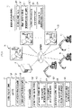
- a work assisting system as one embodiment of the present invention is configured with a work assisting server 10 and plural remote operation devices 20 for performing remote operations of plural work machines 40.
- the work assisting server 10, the remote operation devices 20, and the work machines 40 are configured to be capable of mutual network communication.
- the work assisting server 10 includes a database 102, a first assisting process element 121, and a second assisting process element 122.
- the database 102 stores and retains captured images, work environment images, route guiding images, and so forth in addition to positions and tracks of each of the plural work machines 40.
- the database 102 may be configured with a database server separate from the work assisting server 10.
- Each of the assisting process elements is configured with an arithmetic processing unit (a single-core processor or a multi-core processor or a processor core configuring that), reads necessary data and software from a storage device such as a memory, and executes a computation process following the software for the data as a target, the computation process being described later.
- the remote operation device 20 which configures a client includes a remote control device 200, a remote input interface 210, and a remote output interface 220.
- the remote control device 200 is configured with an arithmetic processing unit (a single-core processor or a multi-core processor or a processor core configuring that), reads necessary data and software from a storage device such as a memory, and executes a computation process following the software for the data as a target.
- the remote input interface 210 includes a remote operation mechanism 211.
- the remote output interface 220 includes an image output device 221 and a remote wireless communication apparatus 222.
- the client may be configured with a portable terminal which cooperates with the remote operation device 20 or has a mutual communication function.
- the portable terminal may have a communication function to communicate with the work assisting server 10.
- the remote operation mechanism 211 includes a traveling operation device, a revolution operation device, a boom operation device, an arm operation device, and a bucket operation device.
- Each of the operation devices has operation levers which accept a rotation operation.
- An operation lever (traveling lever) of the traveling operation device is operated to move a lower traveling body 41 of the work machine 40.
- the traveling lever may also have a traveling pedal.
- a traveling pedal may be provided which is fixed to a base portion or a lower end portion of the traveling lever.
- An operation lever (revolution lever) of the revolution operation device is operated to move a hydraulic revolution motor which configures a revolution mechanism 43 of the work machine 40.
- An operation lever (boom lever) of the boom operation device is operated to move a boom cylinder 442 of the work machine 40.
- An operation lever (arm lever) of the arm operation device is operated to move an arm cylinder 444 of the work machine 40.
- An operation lever (bucket lever) of the bucket operation device is operated to move a bucket cylinder 446
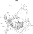
- the operation levers configuring the remote operation mechanism 211 are arranged around a seat St on which an operator is seated, for example.
- the seat St is in a form of a high-back chair with armrests but may be in an arbitrary form on which the operator can be seated such as a form of a low-back chair without a headrest or a form of a chair without a backrest.
- a pair of left and right traveling levers 2110 corresponding to left and right continuous tracks are arranged laterally side by side in a left-right direction in front of the seat St.
- One operation lever may be used as plural operation levers.
- a right operation lever 2111 provided in front of a right frame of the seat St which is illustrated in FIG. 2
- a left operation lever 2112 provided in front of a left frame of the seat St, which is illustrated in FIG.
- Lever patterns may arbitrarily be changed by an operation instruction from the operator.
- the image output device 221 is configured with an obliquely right front image output device 2211, a front image output device 2212, and an obliquely left front image output device 2213 which are respectively arranged in obliquely right front, in front, and in obliquely left front of the seat St, for example.
- the image output devices 2211 to 2213 may further include a speaker (sound output device).
- the work machine 40 includes an actual machine control device 400, an actual machine input interface 410, an actual machine output interface 420, and an actuation mechanism 440.
- the actual machine control device 400 is configured with an arithmetic processing unit (a single-core processor or a multi-core processor or a processor core configuring that), reads necessary data and software from a storage device such as a memory, and executes a computation process following the software for the data as a target.
- arithmetic processing unit a single-core processor or a multi-core processor or a processor core configuring that
- the work machine 40 is a crawler excavator (construction machine), for example, and includes, as illustrated in FIG. 3 , a crawler type lower traveling body 41 and an upper revolving body 42 which is revolvably mounted on the lower traveling body 41 via the revolution mechanism 43.
- a cab (operator cab) 424 is provided to a front left side portion of the upper revolving body 42.
- a work attachment 44 is provided to a front central portion of an upper revolving body 42.
- the actual machine input interface 410 includes an actual machine operation mechanism 411 and an actual machine image-capturing device 412.
- the actual machine operation mechanism 411 includes plural operation levers, which are arranged similarly to the remote operation mechanism 211, around a seat arranged in an internal portion of the cab 424.
- a drive mechanism or a robot which receives a signal corresponding to an operation manner of remote operation levers and moves actual machine operation levers based on the received signal, is provided to the cab 424.
- the actual machine image-capturing device 412 is installed in the internal portion of the cab 424, for example, and captures an image of an environment including at least a part of the actuation mechanism 440 through a front window of the cab 424.
- the actual machine output interface 420 includes an actual machine wireless communication apparatus 422.
- the work attachment 44 as the actuation mechanism includes a boom 441 which is attached to the upper revolving body 42 to be capable of derricking, an arm 443 which is rotatably coupled with a distal end of the boom 441, and a bucket 445 which is rotatably coupled with a distal end of the arm 443.
- the boom cylinder 442, the arm cylinder 444, and the bucket cylinder 446 which are configured with hydraulic cylinders capable of extending and contracting are attached.
- the boom cylinder 442 is interposed between the boom 441 and the upper revolving body 42 such that the boom cylinder 442 extends and contracts by being supplied with hydraulic oil so as to rotate the boom 441 in a derricking direction.
- the arm cylinder 444 is interposed between the arm 443 and the boom 441 such that the arm cylinder 444 extends and contracts by being supplied with hydraulic oil so as to rotate the arm 443 around a horizontal axis with respect to the boom 441.
- the bucket cylinder 446 is interposed between the bucket 445 and the arm 443 such that the bucket cylinder 446 extends and contracts by being supplied with hydraulic oil so as to rotate the bucket 445 around a horizontal axis with respect to the arm 443.
- “Recognition” of information by configuration elements (arithmetic processing resources or hardware resources) of the present invention represents a concept encompassing processes for preparing the information in all forms in which the information is usable in subsequent processes, such as receiving the information, reading out or searching for the information from storage devices and so forth, writing or registering the information (causing the information to be stored or retained) in storage devices and so forth, and estimating, determining, identifying, measuring, and predicting, and so forth the information by executing a computation process of basic information following a predetermined algorithm, the basic information being obtained by an output signal and/or reception from a sensor, a search, and so forth.
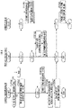
- the remote operation device 20 determines whether or not a designating operation through the remote input interface 210 by the operator is made (STEP 200 in FIG. 4 ).
- a "designating operation” is an operation for selecting the work machine 40 which cooperates with the remote operation device 20 and is a touch operation such as tapping, swiping, flicking, pinching out, or pinching in on a touch panel which configures the remote input interface 210, for example.
- the touch panel displays an actual machine image of the work machine 40 which can become a target of a remote operation, for example, and it is determined whether or not an operation is made to a display position of the actual machine image in the touch panel.
- a series of processes is finished.
- a work environment image request for requesting captured images necessary for an operation of the work machine 40 which cooperates with the remote operation device 20 is transmitted to the work assisting server 10 through the remote wireless communication apparatus 222 (STEP 202 in FIG. 4 ).
- the work environment image request includes at least one of an identifier of the remote operation device 20 and an identifier of the operator.
- the first assisting process element 121 transmits the work environment image request to the concerned work machine 40 (C10 in FIG. 4 ).
- the actual machine control device 400 acquires captured images through the actual machine image-capturing device 412 (STEP 402 in FIG. 4 ).
- the actual machine control device 400 transmits captured image data which represent the captured images to the work assisting server 10 through the actual machine wireless communication apparatus 422 (STEP 404 in FIG. 4 ).
- work environment image data data which represent all or a part of the captured images themselves or simulated work environment images generated based on those
- a time series of the work environment image data is registered in or stored and retained in the database 102 (STEP 114 in FIG. 4 ).
- the remote operation device 20 receives the work environment image data through the remote wireless communication apparatus 222 (C20 in FIG. 4 ), the work environment images corresponding to the work environment image data are output to the image output device 221 (STEP 204 in FIG. 4 ). Accordingly, for example, as illustrated in FIG. 6 , the work environment image, which includes the boom 441, the arm 443, the bucket 445, and the arm cylinder 444 as a part of the work attachment 44 as the actuation mechanism whose image is captured by the actual machine image-capturing device 412 mounted on the work machine 40 which cooperates with the remote operation device 20, is displayed on the image output device 221.
- an operation manner of the remote operation mechanism 211 is recognized by the remote control device 200 (STEP 206 in FIG. 4 ), and a remote operation command corresponding to the operation manner is transmitted to the work assisting server 10 through the remote wireless communication apparatus 222 (STEP 208 in FIG. 4 ).
- the first assisting process element 121 transmits the remote operation command to the work machine 40 (C12 in FIG. 4 ).
- the actual machine control device 400 receives an operation command through the actual machine wireless communication apparatus 422 (C42 in FIG. 4 ), actions of the work attachment 44 or the like are controlled (STEP 406 in FIG. 4 ).
- work is executed in which earth in front of the work machine 40 is scooped by the bucket 445, the upper revolving body 42 is revolved, and earth is then dropped from the bucket 445 (see FIG. 6 ).
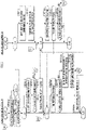
- the remote operation device 20 as a second client determines whether or not a playback operation through the remote input interface 210 by the operator is made (STEP 210 in FIG. 5 ).
- a "playback operation" includes a touch operation for designating one work environment image from a library of the work environment images, the library being registered in the database 102 and displayed on a touch panel, the touch panel configuring the remote input interface 210 and the remote output interface 220, for example.
- a start of playback, a stop of playback, a temporary stop of playback, fast-forwarding, and rewinding of the work environment images are made possible by a remote input interface 210.
- a playback request is transmitted to the work assisting server 10 through the remote wireless communication apparatus 222 (STEP 212 in FIG. 5 ).
- the playback request accompanying the playback operation includes an image identifier for identifying the work environment image designated by the operator.
- the second assisting process element 122 searches for a time series of the work environment images, which is a playback target, as a time series of a designated work environment images from the database 102 based on the image identifiers included in the playback request (STEP 120 in FIG. 5 ).
- the second assisting process element 122 transmits data which represent a time series of designated work environment images to the remote operation device 20 (STEP 121 in FIG. 5 ).
- the remote operation device 20 receives the work environment image data through the remote wireless communication apparatus 222 (C21 in FIG. 5 )
- the work environment images corresponding to the work environment image data are played back in or output to the image output device 221 (STEP 214 in FIG. 5 ).
- the respective work environment images a movie or intermittent still images
- the work environment images including the boom 441, the arm 443, the bucket 445, and the arm cylinder 444 as a part of the work attachment 44 as the actuation mechanism are displayed on the image output device 221 in a time-series manner.
- the remote control device 200 determines whether or not a playback stop operation through an operation by the remote input interface 210 is made (STEP 216 in FIG. 5 ).
- the remote control device 200 transmits a playback stop request to the work assisting server 10 through the remote wireless communication apparatus 222 which configures the remote output interface 220 (STEP 218 in FIG. 5 ).
- the playback stop request includes a playback stop time point of the time series of the work environment images as a designated time point.
- the second assisting process element 122 transmits simulation image data which represent the simulation situation to the remote operation device 20 (STEP 123 in FIG. 5 ).
- a simulation image is output on the image output device 221 which configures the remote output interface 220 (STEP 220 in FIG. 5 ).
- the image output device 221 may output a simulation image instead of the work environment image in a stop state and may output the work environment image in the stop state in a corner of the simulation image.
- the remote control device 200 determines whether or not a simulation stop operation through the remote input interface 210 is made (STEP 222 in FIG. 5 ).
- the remote control device 200 transmits a simulation stop request to the work assisting server 10 through the remote wireless communication apparatus 222 (STEP 228 in FIG. 5 ).
- the remote control device 200 recognizes the operation manner of the remote operation mechanism 211 (STEP 224 in FIG. 5 ), and a simulation operation command corresponding to the operation manner is transmitted to the work assisting server 10 through the remote wireless communication apparatus 222 (STEP 226 in FIG. 5 ).
- the second assisting process element 122 recognizes the simulation situation corresponding to the simulation operation command (STEP 122 in FIG. 5 ). For example, in a case where the operation manner of the remote operation mechanism 211 is to realize a situation where the boom 441 is caused to rise with respect to the upper revolving body 42 and the whole work attachment 44 is thereby caused to rise, a situation where the work attachment 44 acts in such a way in a simulation is recognized as the simulation situation.
- the second assisting process element 122 transmits data which represent simulation images to the remote operation device 20 (STEP 123 in FIG. 5 ). Then, the second assisting process element 122 determines whether or not the simulation stop request is made (STEP 124 in FIG. 5 ). In a case where the determination result is affirmative (YES in STEP 124 in FIG. 5 ), a series of processes is finished. In a case where the determination result is negative (NO in STEP 124 in FIG. 5 ), processes subsequent to reception of the simulation operation command are repeated (see C14 ⁇ STEP 122 ⁇ STEP 123 in FIG. 5 ).
- a time series of the work environment images representing an action manner and an environment changing manner of a first work machine is registered in the database 102 (see STEP 114 in FIG. 4 ). Accordingly, archives of time series of various work environment images are accumulated and preserved in the database 102.
- a "first work machine” denotes the work machine 40 which is remotely operated by the first operator and executes work at an actual work site.
- a second operator of the remote operation device 20 configuring the second client can designate one time series of the work environment images from the archives registered in the database 102 through the remote input interface 210 (see STEP 210 in FIG. 5 ). Accordingly, the second operator can browse the time series of the designated work environment images on the remote output interface 220 (see STEP 220 in FIG. 5 and FIG. 7 ).
- the second operator can perform a simulation operation of the second work machine at a virtual work site that is based on the designated work environment images, through the remote operation mechanism 211 which configures the remote input interface 210 (see FIG. 5 ).
- a "second work machine” denotes a work machine which is subjected to a simulation operation by the second operator and is actuated at a virtual work site.
- the second operator can cause the remote output interface 220 to output a time series of the simulation images which represent the action manner and the environment changing manner of the work machine at the virtual work site in accordance with the simulation operation manner (see STEP 224 ⁇ STEP 226 ⁇ C14 ⁇ STEP 122 ⁇ STEP 123 ⁇ STEP 124 ⁇ C22 ⁇ STEP 220 in FIG. 5 and FIG. 7 ).
- the second operator browses a time series of the work environment images which can be used as a suitable reference, then designates one work environment image, which can be used as a more suitable reference, from the time series of the work environment images, performs a simulation operation of the work machine at a virtual work site which is reproduced based on the designated work environment images, and can thereby intend an improvement in operation techniques of the work machine.
- the work assisting server 10 is configured with one or plural servers which are separate from each of the remote operation devices 20 and the work machines 40 (see FIG. 1 ); however, as another embodiment, the work assisting server 10 may be a configuration element of the remote operation device 20 or the work machine 40.
- Each of the configuration elements 121 and 122 of the work assisting server 10 can be a configuration element of each of two or more apparatuses in the remote operation devices 20 and the work machines 40, the two or more apparatuses being capable of mutual communication.
- the second assisting process element 122 may cause the remote output interface 220 which configures the remote operation device 20 to output time series, while superimposing the time series of the simulation images on the designated time series, which is subsequent to a designated time point, in the time series of the designated work environment images.
- the second operator can cause the remote output interface 220 to output the simulation images which represent the action manner and the environment changing manner of the second work machine at the virtual work site, while superimposing the simulation images on the designated time series of the work environment images which is subsequent to a designated time point, in accordance with the simulation operation manner through the remote operation mechanism 211.
- the second operator is caused to recognize the difference between the action manner of the first work machine or the operation manner of the first operator and the environment changing manner, which are to be referred to, and the action manner of the second work machine or the simulation operation manner of the second operator and the environment changing manner at the virtual work site, and a further improvement in his/her operation techniques is intended.
- the second assisting process element 122 may evaluate the difference between the action manner of the first work machine which is represented by the designated time series of the designated work environment images and the action manner of the second work machine which is represented by the time series of the simulation images. For example, an interval between designated parts (for example, the buckets 445) of the respective work attachments 44 of the first work machine and the second work machine may be converted into an actual spatial distance, and a cumulative value or a time average of the conversion results value may thereby be evaluated as the difference.
- the second assisting process element 122 may cause the remote output interface 220 to output information for confirming whether or not redoing of the simulation operation of the second work machine is necessary.
- the remote output interface 220 may be caused to output a reproduction of the designated time series of the designated work environment images. Accordingly, because the second operator is capable of redoing the simulation operation, a further improvement in operation technique is intended.
- the second assisting process element 122 may cause an operation state (for example, inclination angles or positions of the levers 2110, 2111, and 2112) of the remote operation mechanism 211 which configures the second client at a start time point of the simulation operation of the second work machine to agree with an operation state, at a designated time point, of the remote operation mechanism 211 of the remote operation device 20 which configures the first client.
- an operation state for example, inclination angles or positions of the levers 2110, 2111, and 2112
- the second operator can start the simulation operation of the second work machine while using, as a starting point, an operation state of the remote operation mechanism 211 of the remote operation device 20 configuring the second client, the operation state agreeing with an operation state, by the first operator, of the remote operation mechanism 211 of the remote operation device 20 configuring the first client.
- an operation state of the remote operation mechanism 211 of the remote operation device 20 configuring the second client the operation state agreeing with an operation state, by the first operator, of the remote operation mechanism 211 of the remote operation device 20 configuring the first client.
Landscapes
- Engineering & Computer Science (AREA)
- Theoretical Computer Science (AREA)
- Business, Economics & Management (AREA)
- Structural Engineering (AREA)
- Educational Administration (AREA)
- Educational Technology (AREA)
- General Physics & Mathematics (AREA)
- Physics & Mathematics (AREA)
- Mining & Mineral Resources (AREA)
- Civil Engineering (AREA)
- General Engineering & Computer Science (AREA)
- Aviation & Aerospace Engineering (AREA)
- Entrepreneurship & Innovation (AREA)
- Operation Control Of Excavators (AREA)
- Component Parts Of Construction Machinery (AREA)
- Control Of Position, Course, Altitude, Or Attitude Of Moving Bodies (AREA)
Abstract
Description
- The present invention relates to a work assisting server for assisting an improvement in operation techniques of a work machine by an operator based on communication with a client.
- A display device for a construction machine has been suggested, the display device being capable of encouraging an inexperienced operator to perform an optimal operation which brings efficient excavation work (for example, see Patent Literature 1). Specifically, while being associated with respective operation amounts of a first operation unit which operates a tractive force of a vehicle body and a second operation unit which commands and operates a work instrument in a vehicle-body front portion, "a target tractive force value", "a tractive force value in actual excavation work with respect to a target lifting force value", and "a lifting force value", which are in advance set, in excavation work are displayed while being compared with each other. Accordingly, it is intended to encourage an operator to improve fuel efficiency and to perform an operation with high work efficiency in work at each of phases (traveling of a vehicle and a lift by a work instrument).
- [Patent Literature 1]
Japanese Patent Laid-Open No. 2015-040422 - However, in view of an improvement in operation techniques, it is preferable that an operator having little experience in operating work machines gain experience in operation by simulations while referring to situations where skilled operators or the like operate work machines.
- Accordingly, an object of the present invention is to provide a server and so forth that enable an operator to gain experience in operation by a simulation while referring to a situation of an operation of a work machine by the operator himself/herself or another operator.
- The present invention relates to a work assisting server for assisting an improvement in operation techniques of a work machine by an operator based on communication with a client.
- A work assisting server of the present invention includes: a first assisting process element that recognizes a time series of captured images which are acquired through an image-capturing device cooperating with a first work machine based on communication with a first client used by a first operator for operating the first work machine and which represent an action manner and an environment changing manner of the first work machine and that causes a time series of work environment images which correspond to the captured images to be accumulatively stored and retained in a database; and a second assisting process element that causes an output interface of a second client to output a time series of designated work environment images, which are designated through an input interface of the second client, among time series of the work environment images which are stored and retained in the database based on communication with the second client and that causes the output interface of the second client to output a time series of simulation images which represent an action manner and an environment changing manner of a second work machine at a virtual work site, the action manner and the environment changing manner corresponding to a simulation operation by a second operator through the input interface of the second client, based on a designated work environment image at one designated time point, which is designated through the input interface of the second client, in the time series of the designated work environment images.
- A work assisting system of the present invention includes: the work assisting server of the present invention; the first client; and the second client.
- In the work assisting server and the work assisting system (hereinafter, appropriately referred to as "the work assisting server and so forth") of the present invention, the second operator can designate, through the input interface of the second client, one time series of the work environment images from archives of times series of the work environment images or movies that are registered in the database and that correspond to the captured images which represent an operation manner, the action manner, and the environment changing manner of the first work machine by the first operator. As for the time series of the work environment images, for example, a time series of work environment images throughout a period from an execution start time point when the first work machine starts executing a designated task to an execution finishing time point may be defined as a unit which configures an archive. The second operator can browse the time series of the designated work environment images through the output interface of the second client. The first operator may be the same operator as the second operator, that is, the second operator himself/herself in addition to another operator who is different from the second operator.
- The second operator can, through the input interface of the second client, designate the designated work environment image at one designated time point in the time series of the designated work environment images and can perform a simulation operation of the second work machine at the virtual work site that is based on the designated work environment image at the designated time point. The second operator can cause the output interface of the second client to output the time series of the simulation images which represent the action manner and the environment changing manner of the second work machine at the virtual work site in accordance with the simulation operation manner.
- As described above, the second operator browses a time series of the designated work environment images which can be used as a suitable reference, then designates a designated work environment image, which can be used as a more suitable reference, from the time series of the designated work environment images, performs a simulation operation of the second work machine at the virtual work site which is reproduced based on the designated work environment images, and can thereby intend an improvement in operation techniques of the work machine.
-
-
FIG. 1 is an explanatory diagram about a configuration of a work assisting system as one embodiment of the present invention. -
FIG. 2 is an explanatory diagram about a configuration of a remote operation device. -
FIG. 3 is an explanatory diagram about a configuration of a work machine. -
FIG. 4 is an explanatory diagram about a first function of the work assisting system. -
FIG. 5 is an explanatory diagram about a second function of the work assisting system. -
FIG. 6 is an explanatory diagram about a time series of work environment images. -
FIG. 7 is an explanatory diagram about a time series of simulation images. - A work assisting system as one embodiment of the present invention, which is illustrated in
FIG. 1 , is configured with awork assisting server 10 and pluralremote operation devices 20 for performing remote operations ofplural work machines 40. Thework assisting server 10, theremote operation devices 20, and thework machines 40 are configured to be capable of mutual network communication. - The
work assisting server 10 includes adatabase 102, a firstassisting process element 121, and a secondassisting process element 122. Thedatabase 102 stores and retains captured images, work environment images, route guiding images, and so forth in addition to positions and tracks of each of theplural work machines 40. Thedatabase 102 may be configured with a database server separate from thework assisting server 10. Each of the assisting process elements is configured with an arithmetic processing unit (a single-core processor or a multi-core processor or a processor core configuring that), reads necessary data and software from a storage device such as a memory, and executes a computation process following the software for the data as a target, the computation process being described later. - The
remote operation device 20 which configures a client includes aremote control device 200, aremote input interface 210, and aremote output interface 220. Theremote control device 200 is configured with an arithmetic processing unit (a single-core processor or a multi-core processor or a processor core configuring that), reads necessary data and software from a storage device such as a memory, and executes a computation process following the software for the data as a target. Theremote input interface 210 includes aremote operation mechanism 211. Theremote output interface 220 includes animage output device 221 and a remotewireless communication apparatus 222. - The client may be configured with a portable terminal which cooperates with the
remote operation device 20 or has a mutual communication function. The portable terminal may have a communication function to communicate with thework assisting server 10. - The
remote operation mechanism 211 includes a traveling operation device, a revolution operation device, a boom operation device, an arm operation device, and a bucket operation device. Each of the operation devices has operation levers which accept a rotation operation. An operation lever (traveling lever) of the traveling operation device is operated to move alower traveling body 41 of thework machine 40. The traveling lever may also have a traveling pedal. For example, a traveling pedal may be provided which is fixed to a base portion or a lower end portion of the traveling lever. An operation lever (revolution lever) of the revolution operation device is operated to move a hydraulic revolution motor which configures arevolution mechanism 43 of thework machine 40. An operation lever (boom lever) of the boom operation device is operated to move aboom cylinder 442 of thework machine 40. An operation lever (arm lever) of the arm operation device is operated to move anarm cylinder 444 of thework machine 40. An operation lever (bucket lever) of the bucket operation device is operated to move abucket cylinder 446 of thework machine 40. - As illustrated in
FIG. 2 , the operation levers configuring theremote operation mechanism 211 are arranged around a seat St on which an operator is seated, for example. The seat St is in a form of a high-back chair with armrests but may be in an arbitrary form on which the operator can be seated such as a form of a low-back chair without a headrest or a form of a chair without a backrest. - A pair of left and
right traveling levers 2110 corresponding to left and right continuous tracks are arranged laterally side by side in a left-right direction in front of the seat St. One operation lever may be used as plural operation levers. For example, aright operation lever 2111 provided in front of a right frame of the seat St, which is illustrated inFIG. 2 , may function as the boom lever in a case where theright operation lever 2111 is operated in a front-rear direction and may function as the bucket lever in a case where theright operation lever 2111 is operated in the left-right direction. Similarly, aleft operation lever 2112 provided in front of a left frame of the seat St, which is illustrated inFIG. 2 , may function as the arm lever in a case where theleft operation lever 2112 is operated in the front-rear direction and may function as the revolution lever in a case where theleft operation lever 2112 is operated in the left-right direction. Lever patterns may arbitrarily be changed by an operation instruction from the operator. - As illustrated in
FIG. 2 , theimage output device 221 is configured with an obliquely right frontimage output device 2211, a frontimage output device 2212, and an obliquely left frontimage output device 2213 which are respectively arranged in obliquely right front, in front, and in obliquely left front of the seat St, for example. Theimage output devices 2211 to 2213 may further include a speaker (sound output device). - The
work machine 40 includes an actualmachine control device 400, an actualmachine input interface 410, an actualmachine output interface 420, and anactuation mechanism 440. The actualmachine control device 400 is configured with an arithmetic processing unit (a single-core processor or a multi-core processor or a processor core configuring that), reads necessary data and software from a storage device such as a memory, and executes a computation process following the software for the data as a target. - The
work machine 40 is a crawler excavator (construction machine), for example, and includes, as illustrated inFIG. 3 , a crawler type lower travelingbody 41 and an upper revolvingbody 42 which is revolvably mounted on the lower travelingbody 41 via therevolution mechanism 43. A cab (operator cab) 424 is provided to a front left side portion of the upper revolvingbody 42. Awork attachment 44 is provided to a front central portion of an upper revolvingbody 42. - The actual
machine input interface 410 includes an actualmachine operation mechanism 411 and an actual machine image-capturingdevice 412. The actualmachine operation mechanism 411 includes plural operation levers, which are arranged similarly to theremote operation mechanism 211, around a seat arranged in an internal portion of thecab 424. A drive mechanism or a robot, which receives a signal corresponding to an operation manner of remote operation levers and moves actual machine operation levers based on the received signal, is provided to thecab 424. The actual machine image-capturingdevice 412 is installed in the internal portion of thecab 424, for example, and captures an image of an environment including at least a part of theactuation mechanism 440 through a front window of thecab 424. - The actual
machine output interface 420 includes an actual machinewireless communication apparatus 422. - The
work attachment 44 as the actuation mechanism includes aboom 441 which is attached to the upper revolvingbody 42 to be capable of derricking, anarm 443 which is rotatably coupled with a distal end of theboom 441, and abucket 445 which is rotatably coupled with a distal end of thearm 443. To thework attachment 44, theboom cylinder 442, thearm cylinder 444, and thebucket cylinder 446 which are configured with hydraulic cylinders capable of extending and contracting are attached. - The
boom cylinder 442 is interposed between theboom 441 and the upper revolvingbody 42 such that theboom cylinder 442 extends and contracts by being supplied with hydraulic oil so as to rotate theboom 441 in a derricking direction. Thearm cylinder 444 is interposed between thearm 443 and theboom 441 such that thearm cylinder 444 extends and contracts by being supplied with hydraulic oil so as to rotate thearm 443 around a horizontal axis with respect to theboom 441. Thebucket cylinder 446 is interposed between thebucket 445 and thearm 443 such that thebucket cylinder 446 extends and contracts by being supplied with hydraulic oil so as to rotate thebucket 445 around a horizontal axis with respect to thearm 443. - Functions of the work assisting system in the above configuration will be described by using flowcharts illustrated in
FIG. 4 andFIG. 5 . In the flowcharts, a block indicated by "CXX" is used for simplification of descriptions, denotes transmission and/or reception of data, and denotes a conditional branch where a process in a branching direction is executed while transmission and/or reception of the data are used as a condition. - "Recognition" of information by configuration elements (arithmetic processing resources or hardware resources) of the present invention represents a concept encompassing processes for preparing the information in all forms in which the information is usable in subsequent processes, such as receiving the information, reading out or searching for the information from storage devices and so forth, writing or registering the information (causing the information to be stored or retained) in storage devices and so forth, and estimating, determining, identifying, measuring, and predicting, and so forth the information by executing a computation process of basic information following a predetermined algorithm, the basic information being obtained by an output signal and/or reception from a sensor, a search, and so forth.
- The
remote operation device 20 as a first client determines whether or not a designating operation through theremote input interface 210 by the operator is made (STEP 200 inFIG. 4 ). A "designating operation" is an operation for selecting thework machine 40 which cooperates with theremote operation device 20 and is a touch operation such as tapping, swiping, flicking, pinching out, or pinching in on a touch panel which configures theremote input interface 210, for example. The touch panel displays an actual machine image of thework machine 40 which can become a target of a remote operation, for example, and it is determined whether or not an operation is made to a display position of the actual machine image in the touch panel. In a case where the determination result is a negative result such as interruption of the designating operation (NO inSTEP 200 inFIG. 4 ), a series of processes is finished. On the other hand, in a case where the determination result is affirmative (YES inSTEP 200 inFIG. 4 ), a work environment image request for requesting captured images necessary for an operation of thework machine 40 which cooperates with theremote operation device 20 is transmitted to thework assisting server 10 through the remote wireless communication apparatus 222 (STEP 202 inFIG. 4 ). The work environment image request includes at least one of an identifier of theremote operation device 20 and an identifier of the operator. - In a case where the
work assisting server 10 receives the work environment image request, the first assistingprocess element 121 transmits the work environment image request to the concerned work machine 40 (C10 inFIG. 4 ). - In a case where the
work machine 40 receives the work environment image request through the actual machine wireless communication apparatus 422 (C41 inFIG. 4 ), the actualmachine control device 400 acquires captured images through the actual machine image-capturing device 412 (STEP 402 inFIG. 4 ). The actualmachine control device 400 transmits captured image data which represent the captured images to thework assisting server 10 through the actual machine wireless communication apparatus 422 (STEP 404 inFIG. 4 ). - In a case where the
work assisting server 10 receives the captured image data (C11 inFIG. 4 ), work environment image data (data which represent all or a part of the captured images themselves or simulated work environment images generated based on those) corresponding to the captured image data are transmitted to the remote operation device 20 (STEP 112 inFIG. 4 ). Further, a time series of the work environment image data is registered in or stored and retained in the database 102 (STEP 114 inFIG. 4 ). - In a case where the
remote operation device 20 receives the work environment image data through the remote wireless communication apparatus 222 (C20 inFIG. 4 ), the work environment images corresponding to the work environment image data are output to the image output device 221 (STEP 204 inFIG. 4 ). Accordingly, for example, as illustrated inFIG. 6 , the work environment image, which includes theboom 441, thearm 443, thebucket 445, and thearm cylinder 444 as a part of thework attachment 44 as the actuation mechanism whose image is captured by the actual machine image-capturingdevice 412 mounted on thework machine 40 which cooperates with theremote operation device 20, is displayed on theimage output device 221. - In the
remote operation device 20, an operation manner of theremote operation mechanism 211 is recognized by the remote control device 200 (STEP 206 inFIG. 4 ), and a remote operation command corresponding to the operation manner is transmitted to thework assisting server 10 through the remote wireless communication apparatus 222 (STEP 208 inFIG. 4 ). - In a case where the
work assisting server 10 receives the remote operation command, the first assistingprocess element 121 transmits the remote operation command to the work machine 40 (C12 inFIG. 4 ). - In a case where in the
work machine 40, the actualmachine control device 400 receives an operation command through the actual machine wireless communication apparatus 422 (C42 inFIG. 4 ), actions of thework attachment 44 or the like are controlled (STEP 406 inFIG. 4 ). For example, work is executed in which earth in front of thework machine 40 is scooped by thebucket 445, the upper revolvingbody 42 is revolved, and earth is then dropped from the bucket 445 (seeFIG. 6 ). As illustrated inFIG. 6 , in the above work, the work environment image (a movie or intermittent still images) at a time point t = tk (k = 1, 2, 3, 4, 5, 6), for example, is displayed on theimage output device 221. The work environment image at t = t1 represents a situation where immediately after thebucket 445 is moved to an excavation start position, thework attachment 44 is extended forward, and thebucket 445 is pushed to the ground. The work environment image at t = t2 represents a situation where an operation to move thearm 443 to a position closer to thework machine 40 is performed. The work environment image at t = t3 represents a situation where sufficient earth and sand enter thebucket 445 and thebucket 445 is thereafter caused to take a retainment posture in which earth is grasped. The work environment image at t = t4 represents a situation where left revolution is performed while an operation to raise theboom 441 is performed. The work environment image at t = t5 represents a situation where an operation to move thearm 443 away is performed after the left revolution and thebucket 445 is positioned right above an earth discharging position. The work environment image at t = t6 represents a situation where the bucket takes an earth discharging posture and earth falls from thebucket 445. - The
remote operation device 20 as a second client determines whether or not a playback operation through theremote input interface 210 by the operator is made (STEP 210 inFIG. 5 ). A "playback operation" includes a touch operation for designating one work environment image from a library of the work environment images, the library being registered in thedatabase 102 and displayed on a touch panel, the touch panel configuring theremote input interface 210 and theremote output interface 220, for example. A start of playback, a stop of playback, a temporary stop of playback, fast-forwarding, and rewinding of the work environment images are made possible by aremote input interface 210. - In a case where the determination result is negative (NO in
STEP 210 inFIG. 5 ), a series of processes is finished. On the other hand, in a case where the determination result is affirmative (YES inSTEP 210 inFIG. 5 ), a playback request is transmitted to thework assisting server 10 through the remote wireless communication apparatus 222 (STEP 212 inFIG. 5 ). The playback request accompanying the playback operation includes an image identifier for identifying the work environment image designated by the operator. - In a case where the
work assisting server 10 receives the playback request (C13 inFIG. 5 ), the second assistingprocess element 122 searches for a time series of the work environment images, which is a playback target, as a time series of a designated work environment images from thedatabase 102 based on the image identifiers included in the playback request (STEP 120 inFIG. 5 ). - The second assisting
process element 122 transmits data which represent a time series of designated work environment images to the remote operation device 20 (STEP 121 inFIG. 5 ). - In a case where the
remote operation device 20 receives the work environment image data through the remote wireless communication apparatus 222 (C21 inFIG. 5 ), the work environment images corresponding to the work environment image data are played back in or output to the image output device 221 (STEP 214 inFIG. 5 ). Accordingly, for example, as illustrated inFIG. 6 , the respective work environment images (a movie or intermittent still images) at different time points t = t1, t2, t3, t4, t5, and t6, the work environment images including theboom 441, thearm 443, thebucket 445, and thearm cylinder 444 as a part of thework attachment 44 as the actuation mechanism, are displayed on theimage output device 221 in a time-series manner. - The
remote control device 200 determines whether or not a playback stop operation through an operation by theremote input interface 210 is made (STEP 216 inFIG. 5 ). - In a case where the determination result is negative (NO in STEP 216 in
FIG. 5 ), a playback request without the playback operation is transmitted to thework assisting server 10 through the remotewireless communication apparatus 222. As a result, the time series of the work environment images is continuously output on the image output device 221 (see STEP 212 → C13 → STEP 120 →STEP 121 → C21 → STEP 214 inFIG. 5 ). - On the other hand, in a case where the determination result is affirmative (YES in STEP 216 in
FIG. 5 ), theremote control device 200 transmits a playback stop request to thework assisting server 10 through the remotewireless communication apparatus 222 which configures the remote output interface 220 (STEP 218 inFIG. 5 ). In this case, because the playback request without the playback operation is not transmitted to thework assisting server 10, as a result, a playback of the time series of the work environment images on theimage output device 221 is stopped. The playback stop request includes a playback stop time point of the time series of the work environment images as a designated time point. - In a case where the
work assisting server 10 receives the playback stop request (C14 inFIG. 5 ), the second assistingprocess element 122 recognizes a simulation situation based on the work environment image at the designated time point included in the playback stop request (STEP 122 inFIG. 5 ). For example, an action manner and an environment changing manner of the work machine (second work machine) at a virtual work site, which correspond to the work environment image at a designated time point t = tk in the time series of the work environment images illustrated inFIG. 6 , are recognized as the simulation situation. - In addition, the second assisting
process element 122 transmits simulation image data which represent the simulation situation to the remote operation device 20 (STEP 123 inFIG. 5 ). - In a case where in the
remote operation device 20, the simulation image data are received by the remotewireless communication apparatus 222 which configures the remote output interface 220 (C22 inFIG. 5 ), a simulation image is output on theimage output device 221 which configures the remote output interface 220 (STEP 220 inFIG. 5 ). Accordingly, for example, a simulation image, which represents the action manner and the environment changing manner of the work machine (second work machine) at the virtual work site at a time point t = τj (j = 1, 2, ...) indicated inFIG. 7 , is output on theimage output device 221. In this case, theimage output device 221 may output a simulation image instead of the work environment image in a stop state and may output the work environment image in the stop state in a corner of the simulation image. - The
remote control device 200 determines whether or not a simulation stop operation through theremote input interface 210 is made (STEP 222 inFIG. 5 ). - In a case where the determination result is affirmative (YES in
STEP 222 inFIG. 5 ), theremote control device 200 transmits a simulation stop request to thework assisting server 10 through the remote wireless communication apparatus 222 (STEP 228 inFIG. 5 ). - On the other hand, in a case where the determination result is negative (NO in
STEP 222 inFIG. 5 ), theremote control device 200 recognizes the operation manner of the remote operation mechanism 211 (STEP 224 inFIG. 5 ), and a simulation operation command corresponding to the operation manner is transmitted to thework assisting server 10 through the remote wireless communication apparatus 222 (STEP 226 inFIG. 5 ). - In a case where the
work assisting server 10 receives the simulation operation command (C14 inFIG. 5 ), the second assistingprocess element 122 recognizes the simulation situation corresponding to the simulation operation command (STEP 122 inFIG. 5 ). For example, in a case where the operation manner of theremote operation mechanism 211 is to realize a situation where theboom 441 is caused to rise with respect to the upper revolvingbody 42 and thewhole work attachment 44 is thereby caused to rise, a situation where thework attachment 44 acts in such a way in a simulation is recognized as the simulation situation. - The second assisting
process element 122 transmits data which represent simulation images to the remote operation device 20 (STEP 123 inFIG. 5 ). Then, the second assistingprocess element 122 determines whether or not the simulation stop request is made (STEP 124 inFIG. 5 ). In a case where the determination result is affirmative (YES in STEP 124 inFIG. 5 ), a series of processes is finished. In a case where the determination result is negative (NO in STEP 124 inFIG. 5 ), processes subsequent to reception of the simulation operation command are repeated (see C14 →STEP 122 → STEP 123 inFIG. 5 ). - In a case where in the
remote operation device 20, the simulation image data are received by the remotewireless communication apparatus 222 which configures the remote output interface 220 (C22 inFIG. 5 ), a simulation image is output on theimage output device 221 which configures the remote output interface 220 (STEP 220 inFIG. 5 ). Accordingly, for example, a simulation image at a time point t = τj (j = 1, 2, ...) indicated inFIG. 7 is output on theimage output device 221. - The work environment image at t = τ1 represents, as a simulation image, a situation where immediately after the
bucket 445 is moved to an excavation start position, thework attachment 44 is extended forward, and thebucket 445 is pushed to the ground. The work environment image at t = τ2 represents, as a simulation image, a situation where an operation to move thearm 443 to a position closer to thework machine 40 is performed. The work environment image at t = τ3 represents, as a simulation image, a situation where sufficient earth and sand enter thebucket 445 and thebucket 445 is thereafter caused to take a retainment posture in which earth is grasped. The work environment image at t = τ4 represents, as a simulation image, a situation where left revolution is performed while an operation to raise theboom 441 is performed. The work environment image at t = τ5 represents, as a simulation image, a situation where an operation to move thearm 443 away is performed after the left revolution and thebucket 445 is positioned right above an earth discharging position. The work environment image at t = τ6 represents, as a simulation image, a situation where the bucket takes an earth discharging posture and earth falls from thebucket 445. - In the work assisting system in the above configuration and the
work assisting server 10 configuring that, a time series of the work environment images representing an action manner and an environment changing manner of a first work machine, the first work machine being remotely operated by a first operator through theremote operation device 20 which configures the first client, is registered in the database 102 (see STEP 114 inFIG. 4 ). Accordingly, archives of time series of various work environment images are accumulated and preserved in thedatabase 102. A "first work machine" denotes thework machine 40 which is remotely operated by the first operator and executes work at an actual work site. - A second operator of the
remote operation device 20 configuring the second client can designate one time series of the work environment images from the archives registered in thedatabase 102 through the remote input interface 210 (seeSTEP 210 inFIG. 5 ). Accordingly, the second operator can browse the time series of the designated work environment images on the remote output interface 220 (seeSTEP 220 inFIG. 5 andFIG. 7 ). - The second operator can perform a simulation operation of the second work machine at a virtual work site that is based on the designated work environment images, through the
remote operation mechanism 211 which configures the remote input interface 210 (seeFIG. 5 ). A "second work machine" denotes a work machine which is subjected to a simulation operation by the second operator and is actuated at a virtual work site. The second operator can cause theremote output interface 220 to output a time series of the simulation images which represent the action manner and the environment changing manner of the work machine at the virtual work site in accordance with the simulation operation manner (see STEP 224 → STEP 226 →C14 → STEP 122 → STEP 123 → STEP 124 → C22 →STEP 220 inFIG. 5 andFIG. 7 ). - As described above, the second operator browses a time series of the work environment images which can be used as a suitable reference, then designates one work environment image, which can be used as a more suitable reference, from the time series of the work environment images, performs a simulation operation of the work machine at a virtual work site which is reproduced based on the designated work environment images, and can thereby intend an improvement in operation techniques of the work machine.
- In the above embodiment, the
work assisting server 10 is configured with one or plural servers which are separate from each of theremote operation devices 20 and the work machines 40 (seeFIG. 1 ); however, as another embodiment, thework assisting server 10 may be a configuration element of theremote operation device 20 or thework machine 40. Each of theconfiguration elements work assisting server 10 can be a configuration element of each of two or more apparatuses in theremote operation devices 20 and thework machines 40, the two or more apparatuses being capable of mutual communication. - Based on communication with the
remote operation device 20 which configures the second client, the second assistingprocess element 122 may cause theremote output interface 220 which configures theremote operation device 20 to output time series, while superimposing the time series of the simulation images on the designated time series, which is subsequent to a designated time point, in the time series of the designated work environment images. The second operator can cause theremote output interface 220 to output the simulation images which represent the action manner and the environment changing manner of the second work machine at the virtual work site, while superimposing the simulation images on the designated time series of the work environment images which is subsequent to a designated time point, in accordance with the simulation operation manner through theremote operation mechanism 211. - Thus, the second operator is caused to recognize the difference between the action manner of the first work machine or the operation manner of the first operator and the environment changing manner, which are to be referred to, and the action manner of the second work machine or the simulation operation manner of the second operator and the environment changing manner at the virtual work site, and a further improvement in his/her operation techniques is intended.
- The second assisting
process element 122 may evaluate the difference between the action manner of the first work machine which is represented by the designated time series of the designated work environment images and the action manner of the second work machine which is represented by the time series of the simulation images. For example, an interval between designated parts (for example, the buckets 445) of therespective work attachments 44 of the first work machine and the second work machine may be converted into an actual spatial distance, and a cumulative value or a time average of the conversion results value may thereby be evaluated as the difference. - Furthermore, in a case where the difference exceeds a threshold value, the second assisting
process element 122 may cause theremote output interface 220 to output information for confirming whether or not redoing of the simulation operation of the second work machine is necessary. - Accordingly, in a case where the difference between the action manner of the first work machine or the operation manner of the first operator and the environment changing manner and the action manner of the second work machine or the simulation operation manner of the second operator and the environment changing manner at the virtual work site exceeds the threshold value, because it is confirmed that the redoing is necessary through the
remote input interface 210, a further improvement in operation techniques of the second operator is intended. Further, in a case where it is confirmed that the redoing is necessary, theremote output interface 220 may be caused to output a reproduction of the designated time series of the designated work environment images. Accordingly, because the second operator is capable of redoing the simulation operation, a further improvement in operation technique is intended. - Based on communication with the
remote operation device 20 which configures the second client, the second assistingprocess element 122 may cause an operation state (for example, inclination angles or positions of thelevers remote operation mechanism 211 which configures the second client at a start time point of the simulation operation of the second work machine to agree with an operation state, at a designated time point, of theremote operation mechanism 211 of theremote operation device 20 which configures the first client. - Accordingly, the second operator can start the simulation operation of the second work machine while using, as a starting point, an operation state of the
remote operation mechanism 211 of theremote operation device 20 configuring the second client, the operation state agreeing with an operation state, by the first operator, of theremote operation mechanism 211 of theremote operation device 20 configuring the first client. Thus, easiness of learning of the operation techniques of the first operator by the second operator is improved, and a further improvement in operation techniques of the second operator is intended. -
- 10
- work assisting server
- 20
- remote operation device (first client, second client)
- 40
- work machine
- 102
- database
- 121
- first assisting process element
- 122
- second assisting process element
- 210
- remote input interface
- 220
- remote output interface
- 410
- actual machine input interface
- 412
- actual machine image-capturing device
- 420
- actual machine output interface
- 440
- work attachment (actuation mechanism)
Claims (6)
- A work assisting server for assisting an improvement in an operation technique of a work machine by an operator based on communication with a client, the work assisting server comprising:a first assisting process element that recognizes a time series of captured images which are acquired through an image-capturing device cooperating with a first work machine based on communication with a first client used by a first operator for operating the first work machine and which represent an action manner and an environment changing manner of the first work machine and that causes a time series of work environment images which correspond to the captured images to be accumulatively stored and retained in a database; anda second assisting process element that causes an output interface of a second client to output a time series of designated work environment images, which are designated through an input interface of the second client, among time series of the work environment images which are stored and retained in the database based on communication with the second client and that causes the output interface of the second client to output a time series of simulation images which represent an action manner and an environment changing manner of a second work machine at a virtual work site, the action manner and the environment changing manner corresponding to a simulation operation by a second operator through the input interface of the second client, based on a work environment image at one designated time point, which is designated through the input interface of the second client, in the time series of the designated work environment images.
- The work assisting server according to claim 1, wherein
the second assisting process element causes the output interface of the second client to output time series while superimposing the time series of the simulation images on a designated time series, which is subsequent to the designated time point, in the time series of the designated work environment images. - The work assisting server according to claim 2, wherein
in a case where a difference between the action manner of the first work machine which is represented by the designated time series of the designated work environment images and the action manner of the second work machine which is represented by the time series of the simulation images exceeds a threshold value, the second assisting process element causes the output interface of the second client to output information for confirming whether or not redoing of the simulation operation of the second work machine is necessary. - The work assisting server according to any one of claims 1 to 3, whereinthe first assisting process element recognizes a time series of an operation state of a first operation mechanism which configures the first client based on communication with the first client, andbased on communication with the second client, the second assisting process element causes an operation state of a second operation mechanism which configures the second client at a start time point of the simulation operation of the second work machine to agree with the operation state of the first operation mechanism at a time point which corresponds to the one designated work environment image.
- A work assisting system comprising:the work assisting server according to any one of claims 1 to 4;the first client; andthe second client.
- A work assisting method for assisting an improvement in an operation technique of a work machine by an operator based on communication with a client, the work assisting method comprising:executing a first assisting process of recognizing a time series of captured images which are acquired through an image-capturing device cooperating with a first work machine based on communication with a first client used by a first operator for operating the first work machine and which represent an action manner and an environment changing manner of the first work machine and of causing a time series of work environment images which correspond to the captured images to be accumulatively stored and retained in a database; andexecuting a second assisting process of causing an output interface of a second client to output a time series of designated work environment images, which are designated through an input interface of the second client, among time series of the work environment images which are stored and retained in the database based on communication with the second client and of causing the output interface of the second client to output a time series of simulation images which represent an action manner and an environment changing manner of a second work machine at a virtual work site, the action manner and the environment changing manner corresponding to a simulation operation by a second operator through an input interface of the second client, based on a work environment image at one designated time point, which is designated through the input interface of the second client, in the time series of the designated work environment images.
Applications Claiming Priority (2)
| Application Number | Priority Date | Filing Date | Title |
|---|---|---|---|
| JP2019233255A JP7310595B2 (en) | 2019-12-24 | 2019-12-24 | Work support server and work support system |
| PCT/JP2020/038200 WO2021131228A1 (en) | 2019-12-24 | 2020-10-08 | Work assisting server, work assisting method, and work assisting system |
Publications (3)
| Publication Number | Publication Date |
|---|---|
| EP4050163A1 true EP4050163A1 (en) | 2022-08-31 |
| EP4050163A4 EP4050163A4 (en) | 2023-01-11 |
| EP4050163B1 EP4050163B1 (en) | 2025-08-27 |
Family
ID=76574884
Family Applications (1)
| Application Number | Title | Priority Date | Filing Date |
|---|---|---|---|
| EP20904790.1A Active EP4050163B1 (en) | 2019-12-24 | 2020-10-08 | Work assisting server, work assisting method, and work assisting system |
Country Status (5)
| Country | Link |
|---|---|
| US (1) | US20220406211A1 (en) |
| EP (1) | EP4050163B1 (en) |
| JP (2) | JP7310595B2 (en) |
| CN (1) | CN114902311B (en) |
| WO (1) | WO2021131228A1 (en) |
Families Citing this family (14)
| Publication number | Priority date | Publication date | Assignee | Title |
|---|---|---|---|---|
| WO2021124858A1 (en) * | 2019-12-19 | 2021-06-24 | コベルコ建機株式会社 | Remote control device and remote control system |
| JP7534936B2 (en) * | 2020-11-27 | 2024-08-15 | 株式会社小松製作所 | Wheel loader control system, method, and wheel loader |
| US12353205B2 (en) | 2021-08-11 | 2025-07-08 | Doosan Bobcat North America, Inc. | Remote control for a power machine |
| WO2023122742A1 (en) | 2021-12-22 | 2023-06-29 | Clark Equipment Company | Control of multiple power machines |
| JP7826587B2 (en) * | 2022-03-09 | 2026-03-10 | 住友重機械工業株式会社 | Information processing system, information processing device, and program |
| JPWO2024135603A1 (en) * | 2022-12-20 | 2024-06-27 | ||
| JP2024180057A (en) | 2023-06-16 | 2024-12-26 | 株式会社小松製作所 | Display system and display method for work machine |
| DE112024001655T5 (en) | 2023-06-16 | 2026-03-12 | Komatsu Ltd. | Working machine display system and working machine display method |
| JP2025003004A (en) * | 2023-06-23 | 2025-01-09 | コベルコ建機株式会社 | Operating device and operating system |
| JP2025067426A (en) * | 2023-10-13 | 2025-04-24 | コベルコ建機株式会社 | system |
| WO2025181913A1 (en) * | 2024-02-27 | 2025-09-04 | 日本電気株式会社 | Control plan creation device and control plan creation method |
| WO2025181914A1 (en) * | 2024-02-27 | 2025-09-04 | 日本電気株式会社 | Control plan creation device and control plan creation method |
| JP2025174718A (en) * | 2024-05-17 | 2025-11-28 | コベルコ建機株式会社 | Work Machine Operation System |
| JP2026007523A (en) * | 2024-07-03 | 2026-01-16 | コベルコ建機株式会社 | Work support device, work support system, work machine, remote control device, program, and work support method |
Family Cites Families (21)
| Publication number | Priority date | Publication date | Assignee | Title |
|---|---|---|---|---|
| US8944822B2 (en) * | 2005-07-22 | 2015-02-03 | Appareo Systems, Llc | Synchronized video and synthetic visualization system and method |
| US8485822B2 (en) * | 2006-05-31 | 2013-07-16 | Caterpillar Inc. | Simulation system implementing historical machine data |
| US10600256B2 (en) * | 2006-12-13 | 2020-03-24 | Crown Equipment Corporation | Impact sensing usable with fleet management system |
| US8139108B2 (en) * | 2007-01-31 | 2012-03-20 | Caterpillar Inc. | Simulation system implementing real-time machine data |
| US20150004566A1 (en) * | 2013-06-26 | 2015-01-01 | Caterpillar Inc. | Camera Based Scene Recreator for Operator Coaching |
| DE102013011818B4 (en) * | 2013-07-15 | 2023-07-06 | Liebherr-Werk Nenzing Gmbh | Simulator for a working machine |
| JP2015040422A (en) * | 2013-08-22 | 2015-03-02 | 日立建機株式会社 | Display device of construction machine |
| US20150111184A1 (en) * | 2013-10-23 | 2015-04-23 | Harnischfeger Technologies, Inc. | Optimal path of motion for training simulator |
| US10324433B2 (en) * | 2015-04-01 | 2019-06-18 | Caterpillar Inc. | System and method for determination of machine state based on video and audio analytics |
| CN104992582B (en) * | 2015-07-13 | 2017-08-15 | 中国科学院自动化研究所 | A kind of medical science Minimally Invasive Surgery training system based on mixed reality |
| DE102016000353A1 (en) * | 2016-01-14 | 2017-07-20 | Liebherr-Components Biberach Gmbh | Crane, construction machine or industrial truck simulator |
| DE102016000351A1 (en) * | 2016-01-14 | 2017-07-20 | Liebherr-Werk Biberach Gmbh | Crane, construction machine or industrial truck simulator |
| JP6147406B1 (en) * | 2016-02-02 | 2017-06-14 | 株式会社タダノ | Server, remote monitoring system and remote monitoring method |
| CN106920071B (en) * | 2017-02-23 | 2018-03-27 | 广东电网有限责任公司教育培训评价中心 | Substation field operation householder method and system |
| US11200761B2 (en) * | 2017-07-18 | 2021-12-14 | Komatsu Ltd. | Parameter identifying device, simulation device, and parameter identifying method |
| US10569875B2 (en) * | 2017-09-29 | 2020-02-25 | Deere & Company | Using unmanned aerial vehicles (UAVs or drones) in forestry imaging and assessment applications |
| CN108376490A (en) * | 2018-01-03 | 2018-08-07 | 佛山杰致信息科技有限公司 | A kind of simulated teaching software implementation method based on large scale equipment |
| EP3763885B1 (en) * | 2018-03-08 | 2026-05-06 | Sumitomo Heavy Industries, Ltd. | Work machine, information processing device, information processing method, and program |
| WO2019189888A1 (en) * | 2018-03-30 | 2019-10-03 | 住友重機械工業株式会社 | Construction machine operation assistance system, and construction machine |
| JP7143634B2 (en) | 2018-05-29 | 2022-09-29 | コベルコ建機株式会社 | Skill evaluation system and skill evaluation method |
| US11164476B2 (en) * | 2018-05-29 | 2021-11-02 | Cse Software Inc. | Heavy equipment simulation system and methods of operating same |
-
2019
- 2019-12-24 JP JP2019233255A patent/JP7310595B2/en active Active
-
2020
- 2020-10-08 CN CN202080089367.9A patent/CN114902311B/en active Active
- 2020-10-08 US US17/779,238 patent/US20220406211A1/en not_active Abandoned
- 2020-10-08 EP EP20904790.1A patent/EP4050163B1/en active Active
- 2020-10-08 WO PCT/JP2020/038200 patent/WO2021131228A1/en not_active Ceased
-
2023
- 2023-06-29 JP JP2023106584A patent/JP7544198B2/en active Active
Also Published As
| Publication number | Publication date |
|---|---|
| JP2023129430A (en) | 2023-09-14 |
| US20220406211A1 (en) | 2022-12-22 |
| CN114902311B (en) | 2025-02-21 |
| CN114902311A (en) | 2022-08-12 |
| JP7310595B2 (en) | 2023-07-19 |
| JP7544198B2 (en) | 2024-09-03 |
| WO2021131228A1 (en) | 2021-07-01 |
| JP2021103193A (en) | 2021-07-15 |
| EP4050163B1 (en) | 2025-08-27 |
| EP4050163A4 (en) | 2023-01-11 |
Similar Documents
| Publication | Publication Date | Title |
|---|---|---|
| EP4050163B1 (en) | Work assisting server, work assisting method, and work assisting system | |
| US12346107B2 (en) | Remote operation assistance device and remote operation assistance method | |
| JP7012698B2 (en) | Methods and equipment for controlling excavation of excavators | |
| EP3922775B1 (en) | Remote operation system and remote operation server | |
| US12276085B2 (en) | Work assist server, work assist method, and work assist system | |
| US12305363B2 (en) | Remote operation assistance server, remote operation assistance system, and remote operation assistance method | |
| CN115003888A (en) | Remote operation support server, remote operation support method, and remote operation support system | |
| US20210312721A1 (en) | Reproduction device, analysis assistance system, and reproduction method | |
| US20240052594A1 (en) | Work assistance system and work assistance composite system | |
| US11893694B2 (en) | Reproduction apparatus, analysis assistance system, and reproduction method for synchronizing reproduction of a construction machine model | |
| EP4044101B1 (en) | Work assistance server, work assistance method, and work assistance system | |
| US12620142B2 (en) | Remote operation system and remote operation composite system | |
| WO2021106280A1 (en) | Work assist server, work assist method, and work assist system | |
| JP7581995B2 (en) | Imaging function control system and imaging function control method | |
| JP7415480B2 (en) | Work support server and work support system | |
| JP2023032998A (en) | Work support system and work support composite system | |
| WO2021106281A1 (en) | Work assist server, work assist method, and work assist system | |
| WO2025070227A1 (en) | Operation apparatus and operation system | |
| CN120359338A (en) | Construction support system for excavator |
Legal Events
| Date | Code | Title | Description |
|---|---|---|---|
| STAA | Information on the status of an ep patent application or granted ep patent |
Free format text: STATUS: THE INTERNATIONAL PUBLICATION HAS BEEN MADE |
|
| PUAI | Public reference made under article 153(3) epc to a published international application that has entered the european phase |
Free format text: ORIGINAL CODE: 0009012 |
|
| STAA | Information on the status of an ep patent application or granted ep patent |
Free format text: STATUS: REQUEST FOR EXAMINATION WAS MADE |
|
| 17P | Request for examination filed |
Effective date: 20220524 |
|
| AK | Designated contracting states |
Kind code of ref document: A1 Designated state(s): AL AT BE BG CH CY CZ DE DK EE ES FI FR GB GR HR HU IE IS IT LI LT LU LV MC MK MT NL NO PL PT RO RS SE SI SK SM TR |
|
| A4 | Supplementary search report drawn up and despatched |
Effective date: 20221209 |
|
| RIC1 | Information provided on ipc code assigned before grant |
Ipc: E02F 3/43 20060101ALI20221205BHEP Ipc: G09B 19/16 20060101ALI20221205BHEP Ipc: G09B 9/048 20060101ALI20221205BHEP Ipc: G09B 9/042 20060101ALI20221205BHEP Ipc: E02F 9/26 20060101ALI20221205BHEP Ipc: E02F 9/20 20060101AFI20221205BHEP |
|
| DAV | Request for validation of the european patent (deleted) | ||
| DAX | Request for extension of the european patent (deleted) | ||
| GRAP | Despatch of communication of intention to grant a patent |
Free format text: ORIGINAL CODE: EPIDOSNIGR1 |
|
| STAA | Information on the status of an ep patent application or granted ep patent |
Free format text: STATUS: GRANT OF PATENT IS INTENDED |
|
| RIC1 | Information provided on ipc code assigned before grant |
Ipc: E02F 3/43 20060101ALI20250228BHEP Ipc: G09B 19/16 20060101ALI20250228BHEP Ipc: G09B 9/048 20060101ALI20250228BHEP Ipc: G09B 9/042 20060101ALI20250228BHEP Ipc: E02F 9/26 20060101ALI20250228BHEP Ipc: E02F 9/20 20060101AFI20250228BHEP |
|
| INTG | Intention to grant announced |
Effective date: 20250401 |
|
| GRAS | Grant fee paid |
Free format text: ORIGINAL CODE: EPIDOSNIGR3 |
|
| GRAA | (expected) grant |
Free format text: ORIGINAL CODE: 0009210 |
|
| STAA | Information on the status of an ep patent application or granted ep patent |
Free format text: STATUS: THE PATENT HAS BEEN GRANTED |
|
| AK | Designated contracting states |
Kind code of ref document: B1 Designated state(s): AL AT BE BG CH CY CZ DE DK EE ES FI FR GB GR HR HU IE IS IT LI LT LU LV MC MK MT NL NO PL PT RO RS SE SI SK SM TR |
|
| REG | Reference to a national code |
Ref country code: CH Ref legal event code: EP |
|
| REG | Reference to a national code |
Ref country code: DE Ref legal event code: R096 Ref document number: 602020057731 Country of ref document: DE |
|
| REG | Reference to a national code |
Ref country code: IE Ref legal event code: FG4D |
|
| REG | Reference to a national code |
Ref country code: NL Ref legal event code: MP Effective date: 20250827 |
|
| PG25 | Lapsed in a contracting state [announced via postgrant information from national office to epo] |
Ref country code: IS Free format text: LAPSE BECAUSE OF FAILURE TO SUBMIT A TRANSLATION OF THE DESCRIPTION OR TO PAY THE FEE WITHIN THE PRESCRIBED TIME-LIMIT Effective date: 20251227 |
|
| PGFP | Annual fee paid to national office [announced via postgrant information from national office to epo] |
Ref country code: DE Payment date: 20251010 Year of fee payment: 6 |
|
| PGFP | Annual fee paid to national office [announced via postgrant information from national office to epo] |
Ref country code: GB Payment date: 20251010 Year of fee payment: 6 |
|
| PG25 | Lapsed in a contracting state [announced via postgrant information from national office to epo] |
Ref country code: NO Free format text: LAPSE BECAUSE OF FAILURE TO SUBMIT A TRANSLATION OF THE DESCRIPTION OR TO PAY THE FEE WITHIN THE PRESCRIBED TIME-LIMIT Effective date: 20251127 |
|
| REG | Reference to a national code |
Ref country code: LT Ref legal event code: MG9D |
|
| PG25 | Lapsed in a contracting state [announced via postgrant information from national office to epo] |
Ref country code: PT Free format text: LAPSE BECAUSE OF FAILURE TO SUBMIT A TRANSLATION OF THE DESCRIPTION OR TO PAY THE FEE WITHIN THE PRESCRIBED TIME-LIMIT Effective date: 20251229 |
|
| PG25 | Lapsed in a contracting state [announced via postgrant information from national office to epo] |
Ref country code: FI Free format text: LAPSE BECAUSE OF FAILURE TO SUBMIT A TRANSLATION OF THE DESCRIPTION OR TO PAY THE FEE WITHIN THE PRESCRIBED TIME-LIMIT Effective date: 20250827 |
|
| PG25 | Lapsed in a contracting state [announced via postgrant information from national office to epo] |
Ref country code: HR Free format text: LAPSE BECAUSE OF FAILURE TO SUBMIT A TRANSLATION OF THE DESCRIPTION OR TO PAY THE FEE WITHIN THE PRESCRIBED TIME-LIMIT Effective date: 20250827 Ref country code: NL Free format text: LAPSE BECAUSE OF FAILURE TO SUBMIT A TRANSLATION OF THE DESCRIPTION OR TO PAY THE FEE WITHIN THE PRESCRIBED TIME-LIMIT Effective date: 20250827 |
|
| PGFP | Annual fee paid to national office [announced via postgrant information from national office to epo] |
Ref country code: FR Payment date: 20251010 Year of fee payment: 6 |
|
| PG25 | Lapsed in a contracting state [announced via postgrant information from national office to epo] |
Ref country code: GR Free format text: LAPSE BECAUSE OF FAILURE TO SUBMIT A TRANSLATION OF THE DESCRIPTION OR TO PAY THE FEE WITHIN THE PRESCRIBED TIME-LIMIT Effective date: 20251128 |
|
| PG25 | Lapsed in a contracting state [announced via postgrant information from national office to epo] |
Ref country code: SE Free format text: LAPSE BECAUSE OF FAILURE TO SUBMIT A TRANSLATION OF THE DESCRIPTION OR TO PAY THE FEE WITHIN THE PRESCRIBED TIME-LIMIT Effective date: 20250827 |
|
| PG25 | Lapsed in a contracting state [announced via postgrant information from national office to epo] |
Ref country code: LV Free format text: LAPSE BECAUSE OF FAILURE TO SUBMIT A TRANSLATION OF THE DESCRIPTION OR TO PAY THE FEE WITHIN THE PRESCRIBED TIME-LIMIT Effective date: 20250827 |
|
| PG25 | Lapsed in a contracting state [announced via postgrant information from national office to epo] |
Ref country code: PL Free format text: LAPSE BECAUSE OF FAILURE TO SUBMIT A TRANSLATION OF THE DESCRIPTION OR TO PAY THE FEE WITHIN THE PRESCRIBED TIME-LIMIT Effective date: 20250827 Ref country code: BG Free format text: LAPSE BECAUSE OF FAILURE TO SUBMIT A TRANSLATION OF THE DESCRIPTION OR TO PAY THE FEE WITHIN THE PRESCRIBED TIME-LIMIT Effective date: 20250827 |
|
| PG25 | Lapsed in a contracting state [announced via postgrant information from national office to epo] |
Ref country code: RS Free format text: LAPSE BECAUSE OF FAILURE TO SUBMIT A TRANSLATION OF THE DESCRIPTION OR TO PAY THE FEE WITHIN THE PRESCRIBED TIME-LIMIT Effective date: 20251127 |
|
| PG25 | Lapsed in a contracting state [announced via postgrant information from national office to epo] |
Ref country code: ES Free format text: LAPSE BECAUSE OF FAILURE TO SUBMIT A TRANSLATION OF THE DESCRIPTION OR TO PAY THE FEE WITHIN THE PRESCRIBED TIME-LIMIT Effective date: 20250827 |
|
| REG | Reference to a national code |
Ref country code: AT Ref legal event code: MK05 Ref document number: 1830085 Country of ref document: AT Kind code of ref document: T Effective date: 20250827 |
|
| PG25 | Lapsed in a contracting state [announced via postgrant information from national office to epo] |
Ref country code: RO Free format text: LAPSE BECAUSE OF FAILURE TO SUBMIT A TRANSLATION OF THE DESCRIPTION OR TO PAY THE FEE WITHIN THE PRESCRIBED TIME-LIMIT Effective date: 20250827 |
|
| PG25 | Lapsed in a contracting state [announced via postgrant information from national office to epo] |
Ref country code: SM Free format text: LAPSE BECAUSE OF FAILURE TO SUBMIT A TRANSLATION OF THE DESCRIPTION OR TO PAY THE FEE WITHIN THE PRESCRIBED TIME-LIMIT Effective date: 20250827 |
|
| PG25 | Lapsed in a contracting state [announced via postgrant information from national office to epo] |
Ref country code: DK Free format text: LAPSE BECAUSE OF FAILURE TO SUBMIT A TRANSLATION OF THE DESCRIPTION OR TO PAY THE FEE WITHIN THE PRESCRIBED TIME-LIMIT Effective date: 20250827 |
|
| PG25 | Lapsed in a contracting state [announced via postgrant information from national office to epo] |
Ref country code: AT Free format text: LAPSE BECAUSE OF FAILURE TO SUBMIT A TRANSLATION OF THE DESCRIPTION OR TO PAY THE FEE WITHIN THE PRESCRIBED TIME-LIMIT Effective date: 20250827 |
|
| PG25 | Lapsed in a contracting state [announced via postgrant information from national office to epo] |
Ref country code: IT Free format text: LAPSE BECAUSE OF FAILURE TO SUBMIT A TRANSLATION OF THE DESCRIPTION OR TO PAY THE FEE WITHIN THE PRESCRIBED TIME-LIMIT Effective date: 20250827 |
|
| PG25 | Lapsed in a contracting state [announced via postgrant information from national office to epo] |
Ref country code: CZ Free format text: LAPSE BECAUSE OF FAILURE TO SUBMIT A TRANSLATION OF THE DESCRIPTION OR TO PAY THE FEE WITHIN THE PRESCRIBED TIME-LIMIT Effective date: 20250827 |
|
| PG25 | Lapsed in a contracting state [announced via postgrant information from national office to epo] |
Ref country code: SK Free format text: LAPSE BECAUSE OF FAILURE TO SUBMIT A TRANSLATION OF THE DESCRIPTION OR TO PAY THE FEE WITHIN THE PRESCRIBED TIME-LIMIT Effective date: 20250827 Ref country code: EE Free format text: LAPSE BECAUSE OF FAILURE TO SUBMIT A TRANSLATION OF THE DESCRIPTION OR TO PAY THE FEE WITHIN THE PRESCRIBED TIME-LIMIT Effective date: 20250827 |