EP4049918A1 - Front body structure of vehicle - Google Patents
Front body structure of vehicle Download PDFInfo
- Publication number
- EP4049918A1 EP4049918A1 EP22154221.0A EP22154221A EP4049918A1 EP 4049918 A1 EP4049918 A1 EP 4049918A1 EP 22154221 A EP22154221 A EP 22154221A EP 4049918 A1 EP4049918 A1 EP 4049918A1
- Authority
- EP
- European Patent Office
- Prior art keywords
- coupling member
- vehicle
- pair
- portions
- members
- Prior art date
- Legal status (The legal status is an assumption and is not a legal conclusion. Google has not performed a legal analysis and makes no representation as to the accuracy of the status listed.)
- Pending
Links
- 230000008878 coupling Effects 0.000 claims abstract description 238
- 238000010168 coupling process Methods 0.000 claims abstract description 238
- 238000005859 coupling reaction Methods 0.000 claims abstract description 238
- 239000000725 suspension Substances 0.000 claims abstract description 54
- 239000000835 fiber Substances 0.000 claims abstract description 40
- 229920002430 Fibre-reinforced plastic Polymers 0.000 claims abstract description 21
- 239000011151 fibre-reinforced plastic Substances 0.000 claims abstract description 21
- 239000000463 material Substances 0.000 claims abstract description 19
- 229920003002 synthetic resin Polymers 0.000 claims abstract description 14
- 239000000057 synthetic resin Substances 0.000 claims abstract description 14
- 239000010410 layer Substances 0.000 claims description 60
- 229920000049 Carbon (fiber) Polymers 0.000 claims description 12
- 239000004917 carbon fiber Substances 0.000 claims description 12
- 239000011152 fibreglass Substances 0.000 claims description 8
- 239000002344 surface layer Substances 0.000 claims description 7
- 239000003365 glass fiber Substances 0.000 claims description 3
- 238000006073 displacement reaction Methods 0.000 abstract description 22
- 238000005452 bending Methods 0.000 description 19
- 239000004918 carbon fiber reinforced polymer Substances 0.000 description 15
- 239000012528 membrane Substances 0.000 description 15
- 238000013016 damping Methods 0.000 description 9
- 230000000694 effects Effects 0.000 description 9
- 238000005260 corrosion Methods 0.000 description 6
- 230000007797 corrosion Effects 0.000 description 6
- 230000007246 mechanism Effects 0.000 description 5
- 238000012795 verification Methods 0.000 description 5
- 238000010586 diagram Methods 0.000 description 4
- 230000000052 comparative effect Effects 0.000 description 3
- VNWKTOKETHGBQD-UHFFFAOYSA-N methane Chemical compound C VNWKTOKETHGBQD-UHFFFAOYSA-N 0.000 description 3
- 230000007935 neutral effect Effects 0.000 description 3
- 230000015556 catabolic process Effects 0.000 description 2
- 238000006731 degradation reaction Methods 0.000 description 2
- 238000005516 engineering process Methods 0.000 description 2
- 230000005484 gravity Effects 0.000 description 2
- 238000000034 method Methods 0.000 description 2
- 230000000704 physical effect Effects 0.000 description 2
- 229910000838 Al alloy Inorganic materials 0.000 description 1
- 239000004593 Epoxy Substances 0.000 description 1
- 229910000831 Steel Inorganic materials 0.000 description 1
- 239000000853 adhesive Substances 0.000 description 1
- 230000001070 adhesive effect Effects 0.000 description 1
- 239000000956 alloy Substances 0.000 description 1
- 238000004458 analytical method Methods 0.000 description 1
- 230000008901 benefit Effects 0.000 description 1
- 230000008859 change Effects 0.000 description 1
- 230000008602 contraction Effects 0.000 description 1
- -1 for example Substances 0.000 description 1
- 239000000446 fuel Substances 0.000 description 1
- 239000011159 matrix material Substances 0.000 description 1
- 229910052751 metal Inorganic materials 0.000 description 1
- 239000002184 metal Substances 0.000 description 1
- 230000004048 modification Effects 0.000 description 1
- 238000012986 modification Methods 0.000 description 1
- 230000008569 process Effects 0.000 description 1
- 230000002787 reinforcement Effects 0.000 description 1
- 239000012779 reinforcing material Substances 0.000 description 1
- 229920005989 resin Polymers 0.000 description 1
- 239000011347 resin Substances 0.000 description 1
- 239000010959 steel Substances 0.000 description 1
- 238000012916 structural analysis Methods 0.000 description 1
- 229920001187 thermosetting polymer Polymers 0.000 description 1
- 239000013585 weight reducing agent Substances 0.000 description 1
Images







Classifications
-
- B—PERFORMING OPERATIONS; TRANSPORTING
- B62—LAND VEHICLES FOR TRAVELLING OTHERWISE THAN ON RAILS
- B62D—MOTOR VEHICLES; TRAILERS
- B62D25/00—Superstructure or monocoque structure sub-units; Parts or details thereof not otherwise provided for
- B62D25/08—Front or rear portions
- B62D25/088—Details of structures as upper supports for springs or dampers
-
- B—PERFORMING OPERATIONS; TRANSPORTING
- B62—LAND VEHICLES FOR TRAVELLING OTHERWISE THAN ON RAILS
- B62D—MOTOR VEHICLES; TRAILERS
- B62D25/00—Superstructure or monocoque structure sub-units; Parts or details thereof not otherwise provided for
- B62D25/08—Front or rear portions
- B62D25/082—Engine compartments
-
- B—PERFORMING OPERATIONS; TRANSPORTING
- B62—LAND VEHICLES FOR TRAVELLING OTHERWISE THAN ON RAILS
- B62D—MOTOR VEHICLES; TRAILERS
- B62D25/00—Superstructure or monocoque structure sub-units; Parts or details thereof not otherwise provided for
- B62D25/08—Front or rear portions
- B62D25/14—Dashboards as superstructure sub-units
-
- B—PERFORMING OPERATIONS; TRANSPORTING
- B62—LAND VEHICLES FOR TRAVELLING OTHERWISE THAN ON RAILS
- B62D—MOTOR VEHICLES; TRAILERS
- B62D29/00—Superstructures, understructures, or sub-units thereof, characterised by the material thereof
- B62D29/04—Superstructures, understructures, or sub-units thereof, characterised by the material thereof predominantly of synthetic material
-
- B—PERFORMING OPERATIONS; TRANSPORTING
- B62—LAND VEHICLES FOR TRAVELLING OTHERWISE THAN ON RAILS
- B62D—MOTOR VEHICLES; TRAILERS
- B62D29/00—Superstructures, understructures, or sub-units thereof, characterised by the material thereof
- B62D29/04—Superstructures, understructures, or sub-units thereof, characterised by the material thereof predominantly of synthetic material
- B62D29/043—Superstructures
Definitions
- the present invention relates to a front body structure of a vehicle in which a dash member is coupled to a suspension tower member by a coupling member made of fiber reinforced plastic including fibers impregnated with a synthetic resin material.
- the vehicle body bends and deforms when receiving a large load via the damper mechanism of the suspension device of the vehicle since the top portions (referred to as the suspension tower top portions) of suspension tower members provided in the vehicle body support the damper mechanism.
- the body torsional mode occurs because suspension tower top portions are displaced vertically when the vehicle turns, so the operational safety of the vehicle and the riding comfort of the occupants may be degraded.
- the front body structure of a vehicle in the patent document 1 has an object of suppressing the vertical displacement of the suspension tower top portions and includes a dash panel that separates the vehicle interior from the engine room, a cowl portion mounted on this dash panel, a pair of left and right front side frames extending forward in the front-rear direction of the vehicle body from the left and right end portions of the dash panel, and a pair of left and right suspension tower members, coupled to the outer portions in the vehicle width direction of the pair of front side frames, that project upward to support the upper portions of the dampers of the suspension device, in which a pair of left and right metal suspension tower bars that couple the cowl portion to the suspension tower members are provided.
- fiber reinforced plastic such as, for example, carbon fiber reinforced plastic (CFRP) including impregnated carbon fibers has physical properties of high specific strength (strength/specific gravity) and high specific rigidity (rigidity/specific gravity), which are so-called lightness and strength•rigidity, so carbon fiber reinforced plastic is widely used as structural materials for aircraft, vehicles, and the like. Since mechanical properties such as strength are provided by carbon fibers and the stress transfer function and the fiber protection function between carbon fibers are provided by the base material resin (matrix), this carbon fiber reinforced plastic forms an anisotropic material whose physical properties differ greatly between the fiber direction in which the fibers extend and the non-fiber direction (so-called load direction).
- CFRP carbon fiber reinforced plastic
- the suspension tower bars in patent document 2 couple the suspension tower top portions of a pair of left and right suspension tower members to each other or the pair of suspension tower top portions and the dash member (for example, the cowl portion) to each other, the body portions of the suspension tower bars are formed by fiber reinforced plastic plate materials, and the fiber reinforced plastic plate materials are formed so that FRP sheets with fiber orientation angles of 0°/90° and FRP sheets with fiber orientation angles of 45°/-45° are stacked alternately.
- the suspension tower members fall inward and the cowl portion is displaced vertically like a bow during a travel on a rough road, torsional displacement is caused between the suspension tower top portions and the dash member including the cowl portion. Since the membrane vibration mode occurs in the panel members such as the floor panel due to the torsional displacement between the suspension tower top portions and the dash member, the travel noise performance of the vehicle may degrade.
- the membrane vibration mode of the panel member can be suppressed by increasing the mounting rigidity of the suspension tower members or increasing the plate thickness of the dash member including the cowl portion, but there is a concern that the weight of the car body increases inevitably.
- the vertical displacement of the suspension tower top portions can be reduced by providing the suspension tower bars that firmly couple the suspension tower top portions of the pair of the suspension tower members to the cowl portion as in the technologies in the patent documents 1 and 2. That is, since the body torsional mode can be suppressed by the bending rigidity of the suspension tower bars, the riding comfort can be improved.
- suspension tower bars that couple the suspension tower members to the cowl portion can suppress the body torsional mode, but cannot suppress the membrane vibration mode.
- An object of the present invention is to provide a front body structure of a vehicle and the like that can reduce the vertical displacement of the top portions of the suspension towers and damp vibrations in the torsional direction between the top portions of the suspension towers and the dash member without increasing the weight of the vehicle body.
- a front body structure of a vehicle including: a dash member that extends in a vehicle width direction and separates a vehicle interior from an engine room; a pair of left and right front side frames that extend forward in a vehicle front-rear direction from left and right end portions of the dash member; and a pair of left and right suspension tower members fixed to the pair of front side frames, the pair of left and right suspension tower members projecting upward to support upper portions of dampers of a suspension device, in which a first coupling member that couples the dash member to a suspension member is provided, the first coupling member has a reinforced layer portion made of fiber reinforced plastic in which fibers are impregnated with a synthetic resin material, and the fibers of the reinforced layer portion are oriented so that fibers extending in a longitudinal direction of the first coupling member are more than fibers extending in directions other than the longitudinal direction.
- the vertical displacement of the suspension top portions can be reduced and the body torsional mode can be suppressed by using the bending rigidity of the first coupling member.
- the first coupling member has the reinforced layer portion made of the fiber reinforced plastic in which fibers are impregnated with the synthetic resin material and the fibers of the reinforced layer portion are oriented so that the fibers extending in the longitudinal direction of the first coupling member are more than the fibers extending in the directions other than the longitudinal direction, the torsional displacement between the upper portions of the suspension tower members and the dash member can be converted to the torsional displacement of the first coupling member and the vibration damping capacity of the vehicle is increased and the membrane vibration mode is suppressed.
- the front body structure of a vehicle further includes a pair of left and right first coupling members that couple the dash member to the pair of suspension tower members, the first coupling member being one of the pair of left and right first coupling members; a second coupling member that couples rear end portions of the pair of first coupling members to each other; a pair of left and right front fixing members that fix front end portions of the pair of first coupling members to the pair of suspension tower members; and a pair of left and right rear fixing members that connect, at connection portions, rear end portions of the pair of first coupling members to side end portions of the second coupling member and fixes the connection portions to the dash member, in which the pair of first coupling members and the second coupling member are substantially U-shaped in plan view.
- the pair of left and right first coupling members can be configured as a single component and the ease of handling can be improved.
- the coupling members can be formed long and linearly and the anisotropy tendency of the coupling members can be increased
- the first coupling member has a bent portion that projects upward and extends in the vehicle width direction. According to this structure, at the time of a front collision of the vehicle, the broken portion of the first coupling member can be guided to the upper rear, whereby the interference between components such as pipes disposed around the engine and the broken portion can be avoided.
- the first coupling member and the second coupling member form a closed cross section extending in the longitudinal direction by fitting an inner member having a substantially U-shaped cross section to an outer member having a substantially U-shaped cross section.
- the closed cross section formed in cooperation by the outer member and the inner member can increase the torsional rigidity of the first coupling member and the second coupling member while the bending rigidity of the first coupling member and the second coupling member can be controlled by the open cross section formed by one of the outer member and the inner member.
- the closed cross section is asymmetric with respect to a middle line of a cross section orthogonal to the longitudinal direction in the cross section. According to this structure, even when a bending load is input to the first coupling member and the second coupling member, the bending load can be easily converted to the torsional displacement of the first coupling member and second coupling member.
- the first coupling member in particular the outer member and the inner member (32), each include an upper wall portion and a pair of side wall portions, extending downward from both end portions parallel to the longitudinal direction of the upper wall portion.
- each of the side wall portions comprises a front and rear portion with an intermediate portion arranged in between when seen in the longitudinal direction of the first coupling member.
- the first and second portion are characterized by a larger width compared to the intermediate portion, i.e. extend further in the vertical direction than the intermediate portion.
- the bent portion is formed in the upper wall portion, in particular formed in the intermediate portion of the upper wall portion close to the rear portion of the side wall portions.
- the second coupling member has a reinforced layer portion made of fiber reinforced plastic in which fibers are impregnated with a synthetic resin material.
- the fibers of the reinforced layer portion may be oriented so that fibers extending in a longitudinal direction of the second coupling member are more than fibers extending in directions other than the longitudinal direction of the second coupling member
- a ratio of a volume of the reinforced layer portion to a volume of the first coupling member and the second coupling member is set to 80% or more.
- the practical utility and the suppressive effects of the body torsional mode and the membrane vibration mode can be compatible.
- the suppressive effects of the body torsional mode and the membrane vibration mode are not enough when the ratio of the volume of the reinforced layer portion is less than 80%, but the vehicle body behavior mode can be suppressed while measures against electrolytic corrosion of the first coupling member and the second coupling member are taken when the ratio of the volume of the reinforced layer portion is not less than 80%.
- the pair of first coupling members and/or the second coupling member may have a middle layer portion disposed in the middle portion in thickness direction of the coupling member.
- the pair of first coupling members and/or the second coupling member may further comprise main body layer portions disposed so as to sandwich the middle layer portion.
- the pair of first coupling members and/or the second coupling member may further comprise surface layer portions L3 that cover the surfaces of the main body layer portions.
- the middle layer portion is a fiber reinforced plastic layer having an orientation of 90° in which carbon fibers are arranged so as to extend orthogonally to the longitudinal direction of the first or second coupling member.
- the main body layer portion is a fiber reinforced plastic layer having an orientation of 0° in which carbon fibers are arranged so as to extend in the longitudinal direction of the first or second coupling member.
- the surface layer portion is a glass fiber reinforced plastic (GFRP) layer in which woven glass fibers are impregnated with a synthetic resin.
- GFRP glass fiber reinforced plastic
- the vertical displacement of the top portions of the suspension towers can be reduced and vibrations in the torsional direction between the top portions of the suspension towers and the dash member can be damped without increasing the weight of the vehicle body by providing the coupling member made of the fiber reinforced plastic that is an anisotropic material between the top portions of the suspension towers and the dash member.
- Example 1 of the present invention will be described with reference to Figs. 1 to 22 .
- the vehicle V is configured by a monocoque body and includes a floor panel that forms the bottom surface of a vehicle interior R, a dash panel 1, formed so as to rise up from the front end portion of this floor panel, that separates an engine room E from the vehicle interior R in the vehicle width direction, and a pair of left and right front side frames 2 extending forward from the front surface of this dash panel 1, and a pair of left and right rear side frames (not illustrated) that extend backward from the rear end portion of the floor panel.
- This vehicle V further includes a cowl portion 3, formed on the top of the dash panel 1, that extends in the vehicle width direction and a pair of left and right strut towers 4 (suspension tower members) formed so as to bulge toward the inside of the engine room E. It should be noted that this vehicle V is equipped with an independent strut suspension. In the following descriptions, it is assumed that the direction of arrow F is the front side, the direction of arrow L is the left side, and the direction of arrow U is the upper side.
- the cowl portion 3 is formed in a tub shape by press-forming a steel plate.
- This cowl portion 3 mainly includes a cowl panel 5, a cowl member 6, projecting forward from the front end portion of the cowl panel 5, that forms a tub shaped structure in cooperation with the cowl panel 5, and a cowl grill 7 that partially covers the upper portions of the cowl panel 5 and the cowl member 6.
- a pair of left and right mounting brackets 8 projecting forward are disposed in the left and right end portions of the front wall of the cowl member 6.
- the pairs of mounting brackets 8 are formed in a substantially partial ellipse in plan view and the stud bolts 9 extending vertically upward from the upper surfaces thereof are provided.
- the cowl member 6 can be formed integrally with the dash panel 1, so the dash panel 1 and the cowl member 6 correspond to the dash member according to the present invention.
- the pair of the strut towers 4 are formed so as to project upward. Specifically, the strut towers 4 are formed so as to bulge into the engine room E from the wheel aprons (not illustrated) hung between the apron reinforcements 10 and the front side frames 2 that extend forward and backward. Since the structure of the vehicle V is substantially symmetrical, the right side members and the right side structure will be mainly described below.
- Each of the strut towers 4 includes a hollow cylindrical portion 4a having an axial center that shifts upward toward the rear side, and an annular top portion 4b that closes the upper end portion of this cylindrical portion 4a.
- a plurality of stud bolts 11 extending upward are erected on the top portion 4b.
- This strut tower 4 partially accommodates the upper portion of the damper mechanism (such as the damper and the spring) of the front suspension device (not illustrated).
- the spring seat coupled to the upper end portion of the damper mechanism is fastened and fixed to the top portion 4b by a plurality of fastening members via a mount rubber (any of them are not illustrated).
- this vehicle V is provided with the strut tower bar 20 that structurally couples the pair of strut towers 4 to the cowl member 6 via a plurality of fastening members.
- This strut tower bar 20 is substantially U-shaped in plan view and can suppress the behavior modes (the vehicle body torsional mode and the membrane vibration mode) of the vehicle body that affect the riding comfort.
- the vehicle body torsional mode is a behavior mode used when the vehicle is turning.
- the top portions 4b of the strut towers 4 are displaced in the vertical direction due to the expansion and contraction of the damper mechanism when the vehicle is turning.
- the vehicle body torsional mode about the center axis of the vehicle body occurs due to the vertical displacement of the top portions 4b, causing degradation of steering stability.
- the membrane vibration mode is a behavior mode used when the vehicle travels on a rough road surface.
- the strut towers 4 fall inward in the vehicle width direction while the cowl portion 3 is displaced in the vertical direction like a bow.
- the torsional displacement between the top portions 4b and the cowl portion 3 generates the membrane vibration mode on the panel member, especially on the floor panel having a large area, and causes degradation of riding comfort.
- the strut tower bar 20 will be described again.
- the strut tower bar 20 mainly includes a pair of left and right first coupling members 30 that shift to the inside in the vehicle width direction toward the rear side, a second coupling member 40, extending in the vehicle width direction, that couples the rear end portions of the pair of first coupling members 30, a pair of left and right front fixing members 50 that fix the front end portions of the pair of first coupling members 30 to the stud bolts 11 erected from the top portions 4b of the pair of strut towers 4 via fastening members 23, and a pair of left and right rear fixing members 60, connecting the rear end portions of the pair of first coupling members 30 and the left and right end portions of the second coupling members 40, that fasten and fix the connection portions thereof to the mounting brackets 8 via the stud bolts 9 and the tightening members (not illustrated).
- the main material of the first coupling members 30 and the second coupling member 40 is carbon fiber reinforced plastic (CFRP) in which a reinforcing material (for example, carbon fiber) is impregnated with a synthetic resin (for example, thermosetting epoxy synthetic resin).
- CFRP carbon fiber reinforced plastic
- Carbon fiber includes a fiber bundle (tow) in which a predetermined number of single fibers continuously extending uniformly from one end to the other end in the longitudinal direction of the first coupling members 30 and the second coupling member 40 is bundled.
- the front fixing members 50 and the rear fixing members 60 are made of an aluminum alloy material.
- the front fixing members 50 and the rear fixing members 60 have bending rigidity and torsional rigidity that are larger than in the first coupling members 30 and the second coupling member 40.
- the plate materials of the first coupling members 30 and the second coupling member 40 include three types of layered portions.
- the first coupling members 30 and the second coupling member 40 have a middle layer portion L1 disposed in the middle portion in the thickness direction, main body layer portions L2 disposed so as to sandwich the middle layer portion L1, and surface layer portions L3 that cover the surfaces of the main body layer portions L2.
- the surface layer portions L3 are provided to ensure corrosion resistance (electrolytic corrosion resistance).
- the middle layer portion L1 is a fiber reinforced plastic layer having an orientation of 90° in which the carbon fibers are arranged so as to extend orthogonally to the longitudinal direction.
- the main body layer portion L2 is a fiber reinforced plastic layer having an orientation of 0° in which the carbon fibers described above are arranged so as to extend in the longitudinal direction.
- the surface layer portion L3 is a glass fiber reinforced plastic (GFRP) layer in which woven glass fibers are impregnated with a synthetic resin.
- the volume ratio (L1 to L2 to L3) of these layers are set to, for example, 7 to 80 to 13.
- the first coupling member 30 includes a first coupling member outer 31 that has a substantially U-shaped cross section orthogonal to the longitudinal direction and a first coupling member inner 32, forming a closed cross section C1 extending in the longitudinal direction in cooperation with the first coupling member outer 31 in an intermediate portion in the longitudinal direction, that has a substantially U-shaped cross section.
- the first coupling member outer 31 has open cross sections in both end portions in the longitudinal direction.
- the closed cross section C1 is asymmetric with respect to a middle line C of the cross section orthogonal to the longitudinal direction in the cross section. Accordingly, when a bending load is input to the first coupling member 30, the bending load is converted to torsional displacement of the first coupling member 30.
- the first coupling member outer 31 includes an upper wall portion 31s and a pair of side wall portions 31t, extending downward from both end portions parallel to the longitudinal direction of the upper wall portion 31s.
- the front portion and the rear portion in the longitudinal direction are set to have larger widths (vertical dimensions) than the intermediate portion.
- Openings 31a and 31b are formed in the front portions of the pair of side wall portions 31t in the order from the front and openings 31c and 31d are formed in the rear portions of the pair of side wall portions 31t in the order from the front.
- An opening 31p is formed at the position corresponding to the opening 31a in the front portion of the upper wall portion 31s and an opening 31q is formed at the position corresponding to the opening 31d in the rear portion of the upper wall portion 31s.
- a bent portion 31x that projects upward and extends in the left-right direction is formed in an intermediate portion of the rear side of the upper wall portion 31s.
- the first coupling member inner 32 is shorter in the longitudinal dimension than the first coupling member outer 31.
- the first coupling member inner 32 includes an upper wall portion 32s and a pair of side wall portions 32t, extending downward from both end portions that are parallel to the longitudinal direction of the upper wall portion 32s.
- the front portion and the rear portion in the longitudinal direction are set to have larger widths than the intermediate portion.
- Openings 32b are formed at positions corresponding to the openings 31b in the front portions of the pair of side wall portions 32t and openings 32c are formed at positions corresponding to the openings 31c in the rear portions of the pair of side wall portions 32t.
- a bent portion 32x that projects upward and extends in the left-right direction is formed at a position corresponding to the bent portion 31x in an intermediate portion of the rear side of the upper wall portion 32s.
- Adjusting members 21 having a substantially U-shaped cross section are disposed in both end portions in the longitudinal direction of the first coupling member inner 32.
- the second coupling member 40 is made of the same material as the first coupling member 30 and includes a second coupling member outer 41 having a substantially U-shaped cross section orthogonal to the longitudinal direction and a second coupling member inner 42, having a substantially U-shaped cross section, that forms a closed cross section C2 extending in the longitudinal direction in an intermediate portion in the longitudinal direction in cooperation with the second coupling member outer 41.
- the second coupling member outer 41 has open cross sections in both end portions in the longitudinal direction.
- the closed cross section C2 is symmetric with respect to the middle line of the cross section orthogonal to the longitudinal direction in the cross section and has a substantially trapezoidal shape. This increases the bending rigidity of the second coupling member 40.
- the second coupling member outer 41 includes an upper wall portion 41s and a pair of side wall portions 41t extending downward from both end portions parallel to the longitudinal direction of the upper wall portion 41s.
- the left portion and the right portion in the longitudinal direction are set to have larger widths than an intermediate portion.
- An opening 41a on the outer side in the vehicle width direction and an opening 41b on the inner side in the vehicle width direction are formed in the right portion and the left portion of the pair of side wall portions 41t, respectively, and openings 41p are formed at positions corresponding to the opening 41a in the right end portion and the left end portion of the upper wall portion 41s (see Fig. 6 ).
- the second coupling member inner 42 is shorter in the longitudinal direction than the second coupling member outer 41.
- the second coupling member inner 42 has an upper wall portion 42s and a pair of side wall portions 42t extending downward from both end portions parallel to the longitudinal direction of the upper wall portion 42s.
- the front portion and the rear portion in the longitudinal direction are set to have larger widths than an intermediate portion.
- openings 42b are formed at positions corresponding to the opening 41b (see Fig. 6 ).
- the adjusting members 22 having a substantially U-shaped cross section is disposed in both end portions in the longitudinal direction of the second coupling member inner 42.
- the front fixing member 50 includes a front fixing member outer 51 that is substantially hat-shaped in a cross section orthogonal to the longitudinal direction and a front fixing member inner 52, having substantially U-shaped cross section, that forms a closed cross section extending in the longitudinal direction in the front portion in the longitudinal direction in cooperation with the front fixing member outer 51.
- the front fixing member outer 51 is shorter in the longitudinal direction than the front fixing member inner 52.
- the closed cross section of the front fixing member 50 is disposed so as to correspond to an open cross section region S1b of the first coupling member 30 and an open cross section of the front fixing member 50 is disposed so as to correspond to a closed cross section region S1a of the first coupling member 30.
- the front fixing member outer 51 includes an upper wall portion 51s and a pair of side wall portions 51t extending downward from the both end portions parallel to the axis of the upper wall portion 51s and then extending away from the axis.
- openings 51m and openings 51a are formed in the order from the front.
- openings 51e are formed in the horizontal portions that corresponds to the flange portions.
- an opening 51n and an opening 51p are formed at positions corresponding to the openings 51m and the openings 51a, respectively. It should be noted that stud bolts 11 are inserted into the openings 51e.
- the front fixing member inner 52 has an upper wall portion 52s and a pair of side wall portions 52t extending downward from the both end portions of the upper wall portion 52s that are parallel to the longitudinal direction.
- Each of the side wall portions 52t has an opening 52m at the position corresponding to the opening 51m, an opening 52a at the position corresponding to the opening 51a, and an opening 52b at the position corresponding to the opening 31b (opening 32b) behind the opening 52a.
- An opening 52n is formed at the position corresponding to the opening 51n in front of the upper wall portion 52s.
- the rear fixing member 60 includes a rear fixing member outer 61 that has a substantially U-shaped cross section orthogonal to the longitudinal direction and a rear fixing member inner 62 that has a substantially U-shaped cross section forming a closed cross section extending in the longitudinal direction in cooperation with the rear fixing member outer 61.
- the rear fixing member outer 61 is shorter in the longitudinal direction than the rear fixing member inner 62.
- the outer portion in the vehicle width direction of the closed cross section of the rear fixing member 60 is disposed so as to correspond to the open cross section region S1b of the first coupling member 30 and the inner portion in the vehicle width direction of the closed cross section of the rear fixing member 60 is disposed so as to correspond to an open cross section region S2b of the second coupling member 40.
- the open cross section outside in the vehicle width direction of the rear fixing member 60 is disposed so as to correspond to the closed cross section region S1a of the first coupling member 30 and the open cross section inside in the vehicle width direction of the rear fixing member 60 is disposed so as to correspond to a closed cross section region S2a of the second coupling member 40.
- the rear fixing member outer 61 has an upper wall portion 61s and a pair of side wall portions 61t extending downward from the both end portions parallel to the longitudinal direction of the upper wall portion 61s.
- Each of the side wall portions 61t has an opening 61d corresponding to the opening 31d outside in the vehicle width direction and an opening 61a corresponding to the opening 41a inside in the vehicle width direction.
- the upper wall portion 61s has an opening 61q corresponding to the opening 31q, an opening 61p corresponding to the opening 41p, and a stud hole 61r disposed in an intermediate portion.
- the rear fixing member inner 62 has an upper wall portion 62s and a pair of side wall portions 62t extending downward from the both end portions parallel to the longitudinal direction of the upper wall portion 62s.
- an opening 62c corresponding to the opening 31c, an opening 62d corresponding to the opening 31d, an opening 62a corresponding to the opening 41a, and an opening 62b corresponding to the opening 41b are formed in the order from the outside in the vehicle width direction.
- a stud hole 62r corresponding to the stud hole 61r is provided in the upper wall portion 62s. It should be noted that the stud bolts 9 are inserted into the openings 61r and 62r.
- the end portion inside in the vehicle width direction of the rear fixing member outer 61 and the end portion inside in the vehicle width direction of the rear fixing member inner 62 are substantially parallel to each other in plan view.
- boundary portions B1 between the end portions inside in the vehicle width direction of the rear fixing member outers 61 and the second coupling member outer 41 is disposed outside in the vehicle width direction of boundary portions B2 between the end portions inside in the vehicle width direction of the rear fixing member inners 62 and the second coupling member inner 42 in plan view.
- the pair of left and right boundary portions B1 (B2) are formed so as to be inclined.
- the boundary portion B1 (B2) intersects a neutral axis A at a predetermined angle ⁇ .
- the distance between the pair of boundary portions B1 (B2) is formed so that a distance D1 between the boundary portions on the rear side closest to the cowl portion 3 is the shortest and a distance D2 between the boundary portions on the front side farthest from the cowl portion 3 is the longest.
- the neutral axis A is a line in which the neutral plane of the second coupling member 40 intersects the cross section orthogonal to the longitudinal direction.
- the coupling member inner 32 is fitted and fixed to the first coupling member outer 31 with an adhesive so as to form the closed cross section C1.
- a pair of adjusting members 21 are disposed on one end side and the other end side in the longitudinal direction of the first coupling member inner 32, respectively.
- An opening 21p is formed in the upper wall portion of each of the adjusting members 21 and openings 21a are formed in the side wall portions of each of the adjusting members 21.
- the pair of adjusting members 21 are positioned so that the openings 21a correspond to the openings 31a and 31d of the first coupling member outer 31 and the openings 21p corresponds to the openings 31p and 31q.
- the second coupling member outer 41 is fitted and fixed to the second coupling member inner 42 so as to form the closed cross section C2 in substantially the same procedure.
- the pair of the adjusting members 22 are disposed on one end side and the other end side in the longitudinal direction of the second coupling member inner 42, respectively.
- the opening 22p is formed in the upper wall portion of each of the adjusting members 22 and openings 22a are formed in the side wall portions of each of the adjusting members 22.
- the pair of adjusting members 22 are positioned so that the openings 22a correspond to the openings 41a of the second coupling member outer 41 and the openings 22p correspond to the openings 41p.
- the front fixing member outer 51 covers the end portion of the first coupling member outer 31 from above and the front fixing member inner 52 covers the adjusting members 21 and the first coupling member inner 32 from below, so that the front fixing member outer 51 and the front fixing member inner 52 form the closed cross section and the open cross section.
- the front fixing member 50 surrounds the first coupling member 30 from the outer circumference, the front fixing member 50 has a larger cross-sectional area than the first coupling member 30 and has a larger moment of inertia of area and a larger polar moment of inertia of area than the first coupling member 30.
- the opening 51n coincides with the opening 52n and the opening 51m coincides with the opening 52m. Since the openings 51a and 51p of the front fixing member outer 51 and the openings 52a and 52b of the front fixing member inner 52 are fixed to the first coupling member 30 via screws (not illustrated) or the like, the openings are equivalent to fixing portions.
- the strut tower bar 20 has a thickness corresponding to the two plates (the first coupling member outer 31 and the first coupling member inner 32) in an intermediate portion in the longitudinal direction of first coupling member 30, has a thickness corresponding to the three plates (the first coupling member outer 31, the first coupling member inner 32, and the front fixing member inner 52) in front of this portion, and has a thickness corresponding to the four plates (the front fixing member outer 51, the first coupling member outer 31, the first coupling member inner 32, and the front fixing member inner 52) further in front of this portion.
- the strut tower bar 20 has a thickness corresponding to the four plates (the front fixing member outer 51, the first coupling member outer 31, the adjusting member 21, and the front fixing member inner 52) further in front of this portion, has a thickness corresponding to the three plates (the front fixing member outer 51, the first coupling member outer 31, and the front fixing member inner 52) further in front of this portion, and has a thickness corresponding to the two plates (the front fixing member outer 51 and the front fixing member inner 52) further in front of this portion.
- the rear fixing member outer 61 covers the end portion of the first coupling member outer 31 from above and the rear fixing member inner 62 covers the adjusting member 25 and the first coupling member inner 32 from below, so that the rear fixing member outer 61 and the rear fixing member inner 62 form the closed cross section and the open cross section.
- the rear fixing member 60 surrounds the first coupling member 30 from the outer circumference, the rear fixing member 60 has a larger cross-sectional area than the first coupling member 30 and has a larger moment of inertia of area and a larger polar moment of inertia of area than the first coupling member 30. Since the openings 61d and 61q of the rear fixing member outer 61 and the openings 62c and 62d of the rear fixing member inner 62 are fixed to the first coupling member 30 via screws (not illustrated) or the like, the openings are equivalent to fixing portions.
- the strut tower bar 20 has a thickness corresponding to the two plates (the first coupling member outer 31 and the first coupling member inner 32) in an intermediate portion in the longitudinal direction of first coupling member 30, has a thickness corresponding to the three plates (the first coupling member outer 31, the first coupling member inner 32, and the rear fixing member inner 62) further behind this portion, and has a thickness corresponding to the four plates (the rear fixing member outer 61, the first coupling member outer 31, the adjusting member 25, and the rear fixing member inner 62) further behind this portion.
- the strut tower bar 20 has a thickness corresponding to the three plates (the rear fixing member outer 61, the first coupling member outer 31, and the rear fixing member inner 62) further behind this portion and has a thickness corresponding to the two plates (the rear fixing member outer 61 and the rear fixing member inner 62) further behind this portion.
- the rear fixing member outer 61 covers the end portion of the second coupling member outer 41 from above and the rear fixing member inner 62 covers the adjusting member 22 and the second coupling member inner 42 from below, so that the rear fixing member outer 61 and the rear fixing member inner 62 form the closed cross section and the open cross section. Since the rear fixing member 60 surrounds the second coupling member 40 from the outer circumference, the rear fixing member 60 has a larger cross-sectional area than the second coupling member 40 and has a larger moment of inertia of area and a larger polar moment of inertia of area than the second coupling member 40.
- the openings 61a and 61q of the rear fixing member outer 61 and the openings 62a and 62b of the rear fixing member inner 62 are fixed to the second coupling member 40 via screws (not illustrated) or the like, the openings are equivalent to fixing portions.
- the strut tower bar 20 has a thickness corresponding to the two plates (the second coupling member outer 41 and the second coupling member inner 42) in an intermediate portion in the longitudinal direction of the second coupling member 40, has a thickness corresponding to the three plates (the second coupling member outer 41, the second coupling member inner 42, and the rear fixing member inner 62) further outside in the vehicle width direction, and has a thickness corresponding to the four plates (the rear fixing member outer 61, the first coupling member outer 31, the second coupling member inner 42, and the rear fixing member inner 62) further outside in the vehicle width direction.
- the strut tower bar 20 has a thickness corresponding to the four plates (the rear fixing member outer 61, the first coupling member outer 31, the adjusting member 27, and the rear fixing member inner 62) further outside in the vehicle width direction, has a thickness corresponding to the three plates (the rear fixing member outer 61, the first coupling member outer 31, and the rear fixing member inner 62) further outside in the vehicle width direction, and has a thickness corresponding to the two plates (the rear fixing member outer 61 and the rear fixing member inner 62) further outside in the vehicle width direction.
- the thickness of the strut tower bar 20 only changes within two plates in view of the longitudinal direction. In other words, since change in the member rigidity in the longitudinal direction is suppressed in the strut tower bar 20, the occurrence of local displacement due to the vehicle body behavior mode can be suppressed.
- model M1 is configured by a carbon fiber reinforced plastic layer having an orientation of 0°.
- model M2 is a carbon fiber reinforced plastic layer having an orientation of 0° and 13% of model M2 is a glass fiber reinforced plastic layer having an orientation of 0°, which is disposed on the surface of this carbon fiber reinforced plastic layer.
- model M3 is the carbon fiber reinforced plastic layer having an orientation of 90°, which is disposed in the center
- 80% of model M3 is the carbon fiber reinforced plastic layer having an orientation of 0°, which is disposed on the surface of the carbon fiber reinforced plastic layer having an orientation of 90°
- 13% of model M3 is a glass fiber reinforced plastic layer, which is disposed on the surface of the carbon fiber reinforced plastic layer having an orientation of 0°.
- Fig. 20 illustrates the verification results of bending rigidity. It should be noted that the higher the resonance frequency, the higher the bending rigidity.
- Model M2 has a lower bending rigidity than the model M1 as illustrated in Fig. 20 , but measures against electrolytic corrosion are an essential to ensure reliability at the time of implementation.
- Model M3 has a bending rigidity that is substantially the same as model M2 and can ensure large load/fatigue durability.
- Fig. 21 illustrates the verification results of the vibration damping performance. It should be noted that the higher the modal damping ratio, the larger the amount of accumulated strain energy and the higher the vibration damping effect.
- model M2 has lower vibration damping performance than model M1, but measures against electrolytic corrosion are essential.
- Model M3 has vibration damping performance that is substantially the same as model M2 and can ensure large loads/fatigue durability. As described above, the compatibility between the practical utility and the suppressive effects of the body torsional mode and the membrane vibration mode was confirmed.
- the front body structure of the vehicle V is provided with the first coupling members 30 that couple the cowl member 6 to the strut towers 4, the vertical displacement of the top portions 4b of the strut towers 4 can be reduced and the body torsional mode can be suppressed by using the bending rigidity of the first coupling members 30.
- each of the first coupling members 30 has the reinforced layer portion made of the fiber reinforced plastic in which fibers are impregnated with the synthetic resin material and the fibers of the reinforced layer portion are oriented so that the fibers extending in a longitudinal direction are more than the fibers extending in directions other than the longitudinal direction, the torsional displacement between the top portions of the strut towers 4 and the cowl member 6 can be converted to the torsional displacement of the first coupling members 30 and the membrane vibration mode is suppressed by increasing the vibration damping capacity of the vehicle V.
- the torsional displacement of the first coupling member 30 is converted to strain energy and kinetic energy and this strain energy is temporarily stored in the synthetic resin material of the first coupling members 30 as shear strain. After that, the stored strain energy (shear strain) is converted to kinetic energy again and part thereof is dissipated as thermal energy.
- the front body structure includes the pair of left and right first coupling members 30 that couple the cowl member 6 to the pair of strut towers 4, the second coupling member 40 that couples the rear end portions of the pair of first coupling members 30 to each other, the pair of left and right front fixing members 50 that fix the front end portions of the pair of first coupling members 30 to the pair of strut towers 4, and the pair of left and right rear fixing members 60 that connect, at connection portions, the rear end portions of the pair of first coupling members 30 to the side end portions of the second coupling member 40 and fixes the connecting portions to the cowl member 6, in which the pair of first coupling members 30 and the second coupling member 40 are substantially U-shaped in plan view.
- the pair of left and right first coupling members 30 can be configured as a single component and the ease of handling can be improved.
- the coupling members 21 and 22 can be formed long linearly and the anisotropy tendency of the coupling members 21 and 22 can be increased.
- the broken portion of the first coupling member 30 can be guided to the upper rear at the time of a front collision of the vehicle V, whereby the interference between the components (such as the fuel pipe) disposed around the engine and the broken portion can be avoided.
- the solid line illustrates the state before the collision and the double chain line illustrates the state after the collision.
- first coupling members 30 and the second coupling member 40 form the closed cross section C1 extending in the longitudinal direction by fitting the inner members 21b and 22b with the substantially U-shaped cross sections to the outer members 21a and 22a with the substantially U-shaped cross sections, the bending rigidity of the first coupling members 30 and the second coupling member 40 is increased by the closed cross section C1 formed in cooperation by the outer members and the inner members and the torsional rigidity of the first coupling members 30 and the second coupling member 40 can be controlled by the open cross section formed by one of the outer members 21a and 22a, and the inner members 21b and 22b.
- the closed cross section C1 is asymmetric with respect to the middle line C of the cross section orthogonal to the longitudinal direction in the cross section, even when a bending load is input to the first coupling members 30, the bending load can be easily converted to torsional displacement of first coupling members 30.
- the ratio of the volume of the reinforced layer portion to the volumes of the first coupling members 30 and the second coupling member 40 is set to 80% or more, the compatibility between the practical utility and the suppressive effects of the body torsional mode and the membrane vibration mode can be achieved.
- the suppressive effects of the body torsional mode and the membrane vibration mode are not enough when the ratio of the volume of the reinforced layer portion is less than 80%, but the vehicle body behavior modes can be suppressed while measures against electrolytic corrosion of the first coupling member and the second coupling member are taken when the ratio of the volume of the reinforced layer portion is 80% or more.
- the fibers extending in the longitudinal direction only need to be more than the fibers extending in directions other than the longitudinal direction and the material of the first coupling members 30 and the second coupling member 40 is not limited to carbon fiber.
- the vibration damping performance can be further increased by forming the cross section asymmetrically with respect to the middle line of the cross section.
Landscapes
- Engineering & Computer Science (AREA)
- Chemical & Material Sciences (AREA)
- Combustion & Propulsion (AREA)
- Transportation (AREA)
- Mechanical Engineering (AREA)
- Architecture (AREA)
- Structural Engineering (AREA)
- Body Structure For Vehicles (AREA)
Abstract
Description
- The present invention relates to a front body structure of a vehicle in which a dash member is coupled to a suspension tower member by a coupling member made of fiber reinforced plastic including fibers impregnated with a synthetic resin material.
- It is conventionally known that the vehicle body bends and deforms when receiving a large load via the damper mechanism of the suspension device of the vehicle since the top portions (referred to as the suspension tower top portions) of suspension tower members provided in the vehicle body support the damper mechanism.
- In particular, the body torsional mode occurs because suspension tower top portions are displaced vertically when the vehicle turns, so the operational safety of the vehicle and the riding comfort of the occupants may be degraded.
- The front body structure of a vehicle in the
patent document 1 has an object of suppressing the vertical displacement of the suspension tower top portions and includes a dash panel that separates the vehicle interior from the engine room, a cowl portion mounted on this dash panel, a pair of left and right front side frames extending forward in the front-rear direction of the vehicle body from the left and right end portions of the dash panel, and a pair of left and right suspension tower members, coupled to the outer portions in the vehicle width direction of the pair of front side frames, that project upward to support the upper portions of the dampers of the suspension device, in which a pair of left and right metal suspension tower bars that couple the cowl portion to the suspension tower members are provided. - In recent years, fiber reinforced plastic such as, for example, carbon fiber reinforced plastic (CFRP) including impregnated carbon fibers has physical properties of high specific strength (strength/specific gravity) and high specific rigidity (rigidity/specific gravity), which are so-called lightness and strength•rigidity, so carbon fiber reinforced plastic is widely used as structural materials for aircraft, vehicles, and the like. Since mechanical properties such as strength are provided by carbon fibers and the stress transfer function and the fiber protection function between carbon fibers are provided by the base material resin (matrix), this carbon fiber reinforced plastic forms an anisotropic material whose physical properties differ greatly between the fiber direction in which the fibers extend and the non-fiber direction (so-called load direction).
- A technology for using fiber reinforced plastic has been proposed to achieve both body rigidity and weight reduction. The suspension tower bars in
patent document 2 couple the suspension tower top portions of a pair of left and right suspension tower members to each other or the pair of suspension tower top portions and the dash member (for example, the cowl portion) to each other, the body portions of the suspension tower bars are formed by fiber reinforced plastic plate materials, and the fiber reinforced plastic plate materials are formed so that FRP sheets with fiber orientation angles of 0°/90° and FRP sheets with fiber orientation angles of 45°/-45° are stacked alternately. -
- [Patent document 1]
JP-A-2020-029162 - [Patent document 2]
JP-A-2010-173546 - Since the suspension tower members fall inward and the cowl portion is displaced vertically like a bow during a travel on a rough road, torsional displacement is caused between the suspension tower top portions and the dash member including the cowl portion. Since the membrane vibration mode occurs in the panel members such as the floor panel due to the torsional displacement between the suspension tower top portions and the dash member, the travel noise performance of the vehicle may degrade.
- In such a case, the membrane vibration mode of the panel member can be suppressed by increasing the mounting rigidity of the suspension tower members or increasing the plate thickness of the dash member including the cowl portion, but there is a concern that the weight of the car body increases inevitably.
- The vertical displacement of the suspension tower top portions can be reduced by providing the suspension tower bars that firmly couple the suspension tower top portions of the pair of the suspension tower members to the cowl portion as in the technologies in the
patent documents - However, the suspension tower bars that couple the suspension tower members to the cowl portion can suppress the body torsional mode, but cannot suppress the membrane vibration mode.
- That is, it is not easy to reduce both the vertical displacement of the suspension tower top portions and the torsional displacement between the suspension tower top portions and the dash member at the same time without increasing the weight of the vehicle body.
- An object of the present invention is to provide a front body structure of a vehicle and the like that can reduce the vertical displacement of the top portions of the suspension towers and damp vibrations in the torsional direction between the top portions of the suspension towers and the dash member without increasing the weight of the vehicle body.
- According to a first aspect, there is provided a front body structure of a vehicle including: a dash member that extends in a vehicle width direction and separates a vehicle interior from an engine room; a pair of left and right front side frames that extend forward in a vehicle front-rear direction from left and right end portions of the dash member; and a pair of left and right suspension tower members fixed to the pair of front side frames, the pair of left and right suspension tower members projecting upward to support upper portions of dampers of a suspension device, in which a first coupling member that couples the dash member to a suspension member is provided, the first coupling member has a reinforced layer portion made of fiber reinforced plastic in which fibers are impregnated with a synthetic resin material, and the fibers of the reinforced layer portion are oriented so that fibers extending in a longitudinal direction of the first coupling member are more than fibers extending in directions other than the longitudinal direction.
- According to this structure, since the first coupling member that couples the dash member and the suspension tower members is provided, the vertical displacement of the suspension top portions can be reduced and the body torsional mode can be suppressed by using the bending rigidity of the first coupling member.
- Since the first coupling member has the reinforced layer portion made of the fiber reinforced plastic in which fibers are impregnated with the synthetic resin material and the fibers of the reinforced layer portion are oriented so that the fibers extending in the longitudinal direction of the first coupling member are more than the fibers extending in the directions other than the longitudinal direction, the torsional displacement between the upper portions of the suspension tower members and the dash member can be converted to the torsional displacement of the first coupling member and the vibration damping capacity of the vehicle is increased and the membrane vibration mode is suppressed.
- In a second aspect, the front body structure of a vehicle according to the first aspect further includes a pair of left and right first coupling members that couple the dash member to the pair of suspension tower members, the first coupling member being one of the pair of left and right first coupling members; a second coupling member that couples rear end portions of the pair of first coupling members to each other; a pair of left and right front fixing members that fix front end portions of the pair of first coupling members to the pair of suspension tower members; and a pair of left and right rear fixing members that connect, at connection portions, rear end portions of the pair of first coupling members to side end portions of the second coupling member and fixes the connection portions to the dash member, in which the pair of first coupling members and the second coupling member are substantially U-shaped in plan view. According to this structure, the pair of left and right first coupling members can be configured as a single component and the ease of handling can be improved. In addition, the coupling members can be formed long and linearly and the anisotropy tendency of the coupling members can be increased.
- According to a third aspect, in the front body structure of a vehicle according to the first or second aspect, the first coupling member has a bent portion that projects upward and extends in the vehicle width direction. According to this structure, at the time of a front collision of the vehicle, the broken portion of the first coupling member can be guided to the upper rear, whereby the interference between components such as pipes disposed around the engine and the broken portion can be avoided.
- According to a fourth aspect, in the front body structure of a vehicle according to the second or third aspect, the first coupling member and the second coupling member form a closed cross section extending in the longitudinal direction by fitting an inner member having a substantially U-shaped cross section to an outer member having a substantially U-shaped cross section. According to this structure, the closed cross section formed in cooperation by the outer member and the inner member can increase the torsional rigidity of the first coupling member and the second coupling member while the bending rigidity of the first coupling member and the second coupling member can be controlled by the open cross section formed by one of the outer member and the inner member.
- According to a fifth aspect, in the front body structure of a vehicle according to the fourth aspect, the closed cross section is asymmetric with respect to a middle line of a cross section orthogonal to the longitudinal direction in the cross section. According to this structure, even when a bending load is input to the first coupling member and the second coupling member, the bending load can be easily converted to the torsional displacement of the first coupling member and second coupling member.
- According to a sixth aspect, the first coupling member, in particular the outer member and the inner member (32), each include an upper wall portion and a pair of side wall portions, extending downward from both end portions parallel to the longitudinal direction of the upper wall portion.
- According to a seventh aspect, each of the side wall portions comprises a front and rear portion with an intermediate portion arranged in between when seen in the longitudinal direction of the first coupling member. The first and second portion are characterized by a larger width compared to the intermediate portion, i.e. extend further in the vertical direction than the intermediate portion.
- According to an eighth aspect, the bent portion is formed in the upper wall portion, in particular formed in the intermediate portion of the upper wall portion close to the rear portion of the side wall portions.
- According to a ninth aspect the second coupling member has a reinforced layer portion made of fiber reinforced plastic in which fibers are impregnated with a synthetic resin material. The fibers of the reinforced layer portion may be oriented so that fibers extending in a longitudinal direction of the second coupling member are more than fibers extending in directions other than the longitudinal direction of the second coupling member
- According to a tenth aspect, in the front body structure of a vehicle according to any one of the second to fifth aspects, a ratio of a volume of the reinforced layer portion to a volume of the first coupling member and the second coupling member is set to 80% or more. According to this structure, the practical utility and the suppressive effects of the body torsional mode and the membrane vibration mode can be compatible. The suppressive effects of the body torsional mode and the membrane vibration mode are not enough when the ratio of the volume of the reinforced layer portion is less than 80%, but the vehicle body behavior mode can be suppressed while measures against electrolytic corrosion of the first coupling member and the second coupling member are taken when the ratio of the volume of the reinforced layer portion is not less than 80%.
- According to an eleventh aspect the pair of first coupling members and/or the second coupling member may have a middle layer portion disposed in the middle portion in thickness direction of the coupling member. The pair of first coupling members and/or the second coupling member may further comprise main body layer portions disposed so as to sandwich the middle layer portion.
- According to a twelfth aspect the pair of first coupling members and/or the second coupling member may further comprise surface layer portions L3 that cover the surfaces of the main body layer portions.
- According to a thirteenth aspect the middle layer portion is a fiber reinforced plastic layer having an orientation of 90° in which carbon fibers are arranged so as to extend orthogonally to the longitudinal direction of the first or second coupling member. Additionally or alternatively the main body layer portion is a fiber reinforced plastic layer having an orientation of 0° in which carbon fibers are arranged so as to extend in the longitudinal direction of the first or second coupling member.
- According to a fourteenth aspect, the surface layer portion is a glass fiber reinforced plastic (GFRP) layer in which woven glass fibers are impregnated with a synthetic resin.
- In the front body structure of a vehicle according to the present invention, the vertical displacement of the top portions of the suspension towers can be reduced and vibrations in the torsional direction between the top portions of the suspension towers and the dash member can be damped without increasing the weight of the vehicle body by providing the coupling member made of the fiber reinforced plastic that is an anisotropic material between the top portions of the suspension towers and the dash member.
-
- [
Fig. 1] Fig. 1 is a diagram illustrating a vehicle according to a first example as seen from diagonally above. - [
Fig. 2] Fig. 2 is a perspective view of a front body structure. - [
Fig. 3] Fig. 3 is a plan view of the front body structure. - [
Fig. 4] Fig. 4 is a sectional view taken along line IV-IV inFig. 3 . - [
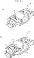
Fig. 5A] Fig. 5A is an explanatory diagram illustrating a body torsional mode of a vehicle body mode. - [
Fig. 5B] Fig. 5B is an explanatory diagram illustrating a membrane vibration mode of the vehicle body mode. - [
Fig. 6] Fig. 6 is a perspective view of a strut tower bar. - [
Fig. 7] Fig. 7 is a plan view of the strut tower bar. - [
Fig. 8] Fig. 8 is a perspective view of a first coupling member outer. - [
Fig. 9] Fig. 9 is a perspective view of a first coupling member inner. - [
Fig. 10] Fig. 10 is a perspective view of a front fixing member outer. - [
Fig. 11] Fig. 11 is a perspective view of a front fixing member inner. - [
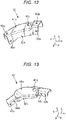
Fig. 12] Fig. 12 is a perspective view of a rear fixing member outer. - [
Fig. 13] Fig. 13 is a perspective view of a rear fixing member inner. - [
Fig. 14] Fig. 14 is a sectional view taken along line XIV-XIV inFig. 7 . - [
Fig. 15] Fig. 15 is a sectional view taken along the line XV-XV inFig. 7 . - [
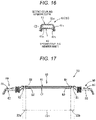
Fig. 16] Fig. 16 is a sectional view taken along line XVI-XVI inFig. 7 . - [
Fig. 17] Fig. 17 is a sectional view taken along line XVII-XVII inFig. 7 . - [
Fig. 18] Fig. 18 is an enlarged sectional view of the first coupling member outer. - [
Fig. 19] Fig. 19 is an exploded perspective view of the first coupling member and the front fixing member. - [
Fig. 20] Fig. 20 is a graph illustrating the results of comparative verification of the bending rigidity. - [
Fig. 21] Fig. 21 is a graph illustrating the results of comparative verification of the vibration attenuation performance. - [
Fig. 22] Fig. 22 is an explanatory diagram of the behavior of the first coupling member at the time of a vehicle collision. - An embodiment of the present invention will be described in detail with reference to the drawings.
- The following description exemplifies application of the present invention to a lower body structure of a vehicle and does not limit the present invention, the application thereof, or the use thereof.
- Example 1 of the present invention will be described with reference to
Figs. 1 to 22 . - First, the overall structure of a vehicle V will be described.
- As illustrated in
Figs. 1 to 4 , the vehicle V is configured by a monocoque body and includes a floor panel that forms the bottom surface of a vehicle interior R, adash panel 1, formed so as to rise up from the front end portion of this floor panel, that separates an engine room E from the vehicle interior R in the vehicle width direction, and a pair of left and right front side frames 2 extending forward from the front surface of thisdash panel 1, and a pair of left and right rear side frames (not illustrated) that extend backward from the rear end portion of the floor panel. - This vehicle V further includes a
cowl portion 3, formed on the top of thedash panel 1, that extends in the vehicle width direction and a pair of left and right strut towers 4 (suspension tower members) formed so as to bulge toward the inside of the engine room E. It should be noted that this vehicle V is equipped with an independent strut suspension. In the following descriptions, it is assumed that the direction of arrow F is the front side, the direction of arrow L is the left side, and the direction of arrow U is the upper side. - The
cowl portion 3 is formed in a tub shape by press-forming a steel plate. - This
cowl portion 3 mainly includes acowl panel 5, acowl member 6, projecting forward from the front end portion of thecowl panel 5, that forms a tub shaped structure in cooperation with thecowl panel 5, and acowl grill 7 that partially covers the upper portions of thecowl panel 5 and thecowl member 6. - As illustrated in
Fig. 4 , a pair of left and right mounting brackets 8 projecting forward are disposed in the left and right end portions of the front wall of thecowl member 6. The pairs of mounting brackets 8 are formed in a substantially partial ellipse in plan view and thestud bolts 9 extending vertically upward from the upper surfaces thereof are provided. It should be noted that thecowl member 6 can be formed integrally with thedash panel 1, so thedash panel 1 and thecowl member 6 correspond to the dash member according to the present invention. - As illustrated in
Figs. 1 to 4 , the pair of the strut towers 4 are formed so as to project upward. Specifically, the strut towers 4 are formed so as to bulge into the engine room E from the wheel aprons (not illustrated) hung between theapron reinforcements 10 and the front side frames 2 that extend forward and backward. Since the structure of the vehicle V is substantially symmetrical, the right side members and the right side structure will be mainly described below. - Each of the strut towers 4 includes a hollow
cylindrical portion 4a having an axial center that shifts upward toward the rear side, and an annulartop portion 4b that closes the upper end portion of thiscylindrical portion 4a. A plurality ofstud bolts 11 extending upward are erected on thetop portion 4b. Thisstrut tower 4 partially accommodates the upper portion of the damper mechanism (such as the damper and the spring) of the front suspension device (not illustrated). The spring seat coupled to the upper end portion of the damper mechanism is fastened and fixed to thetop portion 4b by a plurality of fastening members via a mount rubber (any of them are not illustrated). - Next, a
strut tower bar 20 will be described. - As illustrated in
Figs. 1 to 4 , this vehicle V is provided with thestrut tower bar 20 that structurally couples the pair ofstrut towers 4 to thecowl member 6 via a plurality of fastening members. Thisstrut tower bar 20 is substantially U-shaped in plan view and can suppress the behavior modes (the vehicle body torsional mode and the membrane vibration mode) of the vehicle body that affect the riding comfort. - Here, the behavior modes of the vehicle body will be described.
- The vehicle body torsional mode is a behavior mode used when the vehicle is turning.
- As illustrated by the arrow in
Fig. 5A , thetop portions 4b of the strut towers 4 are displaced in the vertical direction due to the expansion and contraction of the damper mechanism when the vehicle is turning. The vehicle body torsional mode about the center axis of the vehicle body occurs due to the vertical displacement of thetop portions 4b, causing degradation of steering stability. - The membrane vibration mode is a behavior mode used when the vehicle travels on a rough road surface.
- As illustrated by the arrow in
Fig. 5B , when the vehicle travels on a rough road surface, the strut towers 4 fall inward in the vehicle width direction while thecowl portion 3 is displaced in the vertical direction like a bow. The torsional displacement between thetop portions 4b and thecowl portion 3 generates the membrane vibration mode on the panel member, especially on the floor panel having a large area, and causes degradation of riding comfort. - The
strut tower bar 20 will be described again. - As illustrated in
Figs. 6 and 7 , thestrut tower bar 20 mainly includes a pair of left and rightfirst coupling members 30 that shift to the inside in the vehicle width direction toward the rear side, asecond coupling member 40, extending in the vehicle width direction, that couples the rear end portions of the pair offirst coupling members 30, a pair of left and rightfront fixing members 50 that fix the front end portions of the pair offirst coupling members 30 to thestud bolts 11 erected from thetop portions 4b of the pair ofstrut towers 4 viafastening members 23, and a pair of left and rightrear fixing members 60, connecting the rear end portions of the pair offirst coupling members 30 and the left and right end portions of thesecond coupling members 40, that fasten and fix the connection portions thereof to the mounting brackets 8 via thestud bolts 9 and the tightening members (not illustrated). - The main material of the
first coupling members 30 and thesecond coupling member 40 is carbon fiber reinforced plastic (CFRP) in which a reinforcing material (for example, carbon fiber) is impregnated with a synthetic resin (for example, thermosetting epoxy synthetic resin). - Carbon fiber includes a fiber bundle (tow) in which a predetermined number of single fibers continuously extending uniformly from one end to the other end in the longitudinal direction of the
first coupling members 30 and thesecond coupling member 40 is bundled. - The
front fixing members 50 and therear fixing members 60 are made of an aluminum alloy material. - Accordingly, the
front fixing members 50 and therear fixing members 60 have bending rigidity and torsional rigidity that are larger than in thefirst coupling members 30 and thesecond coupling member 40. - The plate materials of the
first coupling members 30 and thesecond coupling member 40 include three types of layered portions. - As illustrated in
Fig. 18 , thefirst coupling members 30 and thesecond coupling member 40 have a middle layer portion L1 disposed in the middle portion in the thickness direction, main body layer portions L2 disposed so as to sandwich the middle layer portion L1, and surface layer portions L3 that cover the surfaces of the main body layer portions L2. The surface layer portions L3 are provided to ensure corrosion resistance (electrolytic corrosion resistance). - The middle layer portion L1 is a fiber reinforced plastic layer having an orientation of 90° in which the carbon fibers are arranged so as to extend orthogonally to the longitudinal direction. The main body layer portion L2 is a fiber reinforced plastic layer having an orientation of 0° in which the carbon fibers described above are arranged so as to extend in the longitudinal direction. The surface layer portion L3 is a glass fiber reinforced plastic (GFRP) layer in which woven glass fibers are impregnated with a synthetic resin. The volume ratio (L1 to L2 to L3) of these layers are set to, for example, 7 to 80 to 13.
- Next, the
first coupling member 30 will be described. - As illustrated in
Figs. 8, 9 ,14, and 15 , thefirst coupling member 30 includes a first coupling member outer 31 that has a substantially U-shaped cross section orthogonal to the longitudinal direction and a first coupling member inner 32, forming a closed cross section C1 extending in the longitudinal direction in cooperation with the first coupling member outer 31 in an intermediate portion in the longitudinal direction, that has a substantially U-shaped cross section. The first coupling member outer 31 has open cross sections in both end portions in the longitudinal direction. The closed cross section C1 is asymmetric with respect to a middle line C of the cross section orthogonal to the longitudinal direction in the cross section. Accordingly, when a bending load is input to thefirst coupling member 30, the bending load is converted to torsional displacement of thefirst coupling member 30. - The first coupling member outer 31 includes an
upper wall portion 31s and a pair ofside wall portions 31t, extending downward from both end portions parallel to the longitudinal direction of theupper wall portion 31s. - Of each of the
side wall portions 31t, the front portion and the rear portion in the longitudinal direction are set to have larger widths (vertical dimensions) than the intermediate portion.Openings side wall portions 31t in the order from the front andopenings side wall portions 31t in the order from the front. Anopening 31p is formed at the position corresponding to theopening 31a in the front portion of theupper wall portion 31s and anopening 31q is formed at the position corresponding to theopening 31d in the rear portion of theupper wall portion 31s. Abent portion 31x that projects upward and extends in the left-right direction is formed in an intermediate portion of the rear side of theupper wall portion 31s. - The first coupling member inner 32 is shorter in the longitudinal dimension than the first coupling member outer 31. The first coupling member inner 32 includes an
upper wall portion 32s and a pair ofside wall portions 32t, extending downward from both end portions that are parallel to the longitudinal direction of theupper wall portion 32s. - Of each of the
side wall portions 32t, the front portion and the rear portion in the longitudinal direction are set to have larger widths than the intermediate portion.Openings 32b are formed at positions corresponding to theopenings 31b in the front portions of the pair ofside wall portions 32t andopenings 32c are formed at positions corresponding to theopenings 31c in the rear portions of the pair ofside wall portions 32t. Abent portion 32x that projects upward and extends in the left-right direction is formed at a position corresponding to thebent portion 31x in an intermediate portion of the rear side of theupper wall portion 32s. Adjustingmembers 21 having a substantially U-shaped cross section are disposed in both end portions in the longitudinal direction of the firstcoupling member inner 32. - Next, the
second coupling member 40 will be described. - As illustrated in
Figs. 16 and 17 , thesecond coupling member 40 is made of the same material as thefirst coupling member 30 and includes a second coupling member outer 41 having a substantially U-shaped cross section orthogonal to the longitudinal direction and a second coupling member inner 42, having a substantially U-shaped cross section, that forms a closed cross section C2 extending in the longitudinal direction in an intermediate portion in the longitudinal direction in cooperation with the second coupling member outer 41. The second coupling member outer 41 has open cross sections in both end portions in the longitudinal direction. The closed cross section C2 is symmetric with respect to the middle line of the cross section orthogonal to the longitudinal direction in the cross section and has a substantially trapezoidal shape. This increases the bending rigidity of thesecond coupling member 40. - The second coupling member outer 41 includes an
upper wall portion 41s and a pair ofside wall portions 41t extending downward from both end portions parallel to the longitudinal direction of theupper wall portion 41s. - Of each of the
side wall portions 41t, the left portion and the right portion in the longitudinal direction are set to have larger widths than an intermediate portion. Anopening 41a on the outer side in the vehicle width direction and anopening 41b on the inner side in the vehicle width direction are formed in the right portion and the left portion of the pair ofside wall portions 41t, respectively, andopenings 41p are formed at positions corresponding to theopening 41a in the right end portion and the left end portion of theupper wall portion 41s (seeFig. 6 ). - As illustrated in
Fig. 17 , the second coupling member inner 42 is shorter in the longitudinal direction than the second coupling member outer 41. The second coupling member inner 42 has anupper wall portion 42s and a pair ofside wall portions 42t extending downward from both end portions parallel to the longitudinal direction of theupper wall portion 42s. Of the side wall portions, the front portion and the rear portion in the longitudinal direction are set to have larger widths than an intermediate portion. In the front portions of the pair of the side wall portions,openings 42b are formed at positions corresponding to theopening 41b (seeFig. 6 ). The adjustingmembers 22 having a substantially U-shaped cross section is disposed in both end portions in the longitudinal direction of the secondcoupling member inner 42. - Next, the
front fixing member 50 will be described. - As illustrated in
Figs. 10, 11 , and15 , thefront fixing member 50 includes a front fixing member outer 51 that is substantially hat-shaped in a cross section orthogonal to the longitudinal direction and a front fixing member inner 52, having substantially U-shaped cross section, that forms a closed cross section extending in the longitudinal direction in the front portion in the longitudinal direction in cooperation with the front fixing member outer 51. The front fixing member outer 51 is shorter in the longitudinal direction than the front fixingmember inner 52. The closed cross section of the front fixingmember 50 is disposed so as to correspond to an open cross section region S1b of thefirst coupling member 30 and an open cross section of the front fixingmember 50 is disposed so as to correspond to a closed cross section region S1a of thefirst coupling member 30. - The front fixing member outer 51 includes an
upper wall portion 51s and a pair ofside wall portions 51t extending downward from the both end portions parallel to the axis of theupper wall portion 51s and then extending away from the axis. - In the vertical portions of the
side wall portions 51t corresponding to wall portions that form the closed cross section,openings 51m andopenings 51a are formed in the order from the front. In the horizontal portions that corresponds to the flange portions,openings 51e are formed. In theupper wall portion 51s, anopening 51n and anopening 51p are formed at positions corresponding to theopenings 51m and theopenings 51a, respectively. It should be noted thatstud bolts 11 are inserted into theopenings 51e. - The front fixing member inner 52 has an
upper wall portion 52s and a pair ofside wall portions 52t extending downward from the both end portions of theupper wall portion 52s that are parallel to the longitudinal direction. Each of theside wall portions 52t has anopening 52m at the position corresponding to theopening 51m, anopening 52a at the position corresponding to theopening 51a, and anopening 52b at the position corresponding to theopening 31b (opening 32b) behind theopening 52a. Anopening 52n is formed at the position corresponding to theopening 51n in front of theupper wall portion 52s. - Next, the
rear fixing member 60 will be described. - As illustrated in
Figs. 12, 13 ,15 , and17 , therear fixing member 60 includes a rear fixing member outer 61 that has a substantially U-shaped cross section orthogonal to the longitudinal direction and a rear fixing member inner 62 that has a substantially U-shaped cross section forming a closed cross section extending in the longitudinal direction in cooperation with the rear fixing member outer 61. The rear fixing member outer 61 is shorter in the longitudinal direction than the rear fixingmember inner 62. The outer portion in the vehicle width direction of the closed cross section of therear fixing member 60 is disposed so as to correspond to the open cross section region S1b of thefirst coupling member 30 and the inner portion in the vehicle width direction of the closed cross section of therear fixing member 60 is disposed so as to correspond to an open cross section region S2b of thesecond coupling member 40. - In addition, the open cross section outside in the vehicle width direction of the
rear fixing member 60 is disposed so as to correspond to the closed cross section region S1a of thefirst coupling member 30 and the open cross section inside in the vehicle width direction of therear fixing member 60 is disposed so as to correspond to a closed cross section region S2a of thesecond coupling member 40. - The rear fixing member outer 61 has an
upper wall portion 61s and a pair ofside wall portions 61t extending downward from the both end portions parallel to the longitudinal direction of theupper wall portion 61s. - Each of the
side wall portions 61t has anopening 61d corresponding to theopening 31d outside in the vehicle width direction and anopening 61a corresponding to theopening 41a inside in the vehicle width direction. - The
upper wall portion 61s has anopening 61q corresponding to theopening 31q, anopening 61p corresponding to theopening 41p, and astud hole 61r disposed in an intermediate portion. - The rear fixing member inner 62 has an
upper wall portion 62s and a pair ofside wall portions 62t extending downward from the both end portions parallel to the longitudinal direction of theupper wall portion 62s. In each of theside wall portions 62t, anopening 62c corresponding to theopening 31c, anopening 62d corresponding to theopening 31d, anopening 62a corresponding to theopening 41a, and anopening 62b corresponding to theopening 41b are formed in the order from the outside in the vehicle width direction. Astud hole 62r corresponding to thestud hole 61r is provided in theupper wall portion 62s. It should be noted that thestud bolts 9 are inserted into theopenings - As illustrated in
Figs. 12 and 13 , the end portion inside in the vehicle width direction of the rear fixing member outer 61 and the end portion inside in the vehicle width direction of the rear fixing member inner 62 are substantially parallel to each other in plan view. - As illustrated in
Fig. 17 , boundary portions B1 between the end portions inside in the vehicle width direction of the rear fixingmember outers 61 and the second coupling member outer 41 is disposed outside in the vehicle width direction of boundary portions B2 between the end portions inside in the vehicle width direction of the rear fixingmember inners 62 and the second coupling member inner 42 in plan view. - As illustrated in
Fig. 7 , the pair of left and right boundary portions B1 (B2) are formed so as to be inclined. - When the
cowl portion 3 is displaced in the vertical direction like a bow with thestrut tower bar 20 attached to the vehicle body, the boundary portion B1 (B2) intersects a neutral axis A at a predetermined angle θ. The distance between the pair of boundary portions B1 (B2) is formed so that a distance D1 between the boundary portions on the rear side closest to thecowl portion 3 is the shortest and a distance D2 between the boundary portions on the front side farthest from thecowl portion 3 is the longest. It should be noted that the neutral axis A is a line in which the neutral plane of thesecond coupling member 40 intersects the cross section orthogonal to the longitudinal direction. - Next, the assembly process of the
strut tower bar 20 will be described. - As illustrated in
Fig. 19 , in thefirst coupling member 30, after theopenings opening members 21 are disposed on one end side and the other end side in the longitudinal direction of the first coupling member inner 32, respectively. Anopening 21p is formed in the upper wall portion of each of the adjustingmembers 21 andopenings 21a are formed in the side wall portions of each of the adjustingmembers 21. - The pair of adjusting
members 21 are positioned so that theopenings 21a correspond to theopenings openings 21p corresponds to theopenings - Also for the
second coupling member 40, the second coupling member outer 41 is fitted and fixed to the second coupling member inner 42 so as to form the closed cross section C2 in substantially the same procedure. - The pair of the adjusting
members 22 are disposed on one end side and the other end side in the longitudinal direction of the second coupling member inner 42, respectively. Theopening 22p is formed in the upper wall portion of each of the adjustingmembers 22 andopenings 22a are formed in the side wall portions of each of the adjustingmembers 22. The pair of adjustingmembers 22 are positioned so that theopenings 22a correspond to theopenings 41a of the second coupling member outer 41 and theopenings 22p correspond to theopenings 41p. - The front fixing member outer 51 covers the end portion of the first coupling member outer 31 from above and the front fixing member inner 52 covers the adjusting
members 21 and the first coupling member inner 32 from below, so that the front fixing member outer 51 and the front fixing member inner 52 form the closed cross section and the open cross section. - Since the
front fixing member 50 surrounds thefirst coupling member 30 from the outer circumference, thefront fixing member 50 has a larger cross-sectional area than thefirst coupling member 30 and has a larger moment of inertia of area and a larger polar moment of inertia of area than thefirst coupling member 30. - At this time, the
opening 51n coincides with theopening 52n and theopening 51m coincides with theopening 52m. Since theopenings openings first coupling member 30 via screws (not illustrated) or the like, the openings are equivalent to fixing portions. - As illustrated in
Fig. 15 , thestrut tower bar 20 has a thickness corresponding to the two plates (the first coupling member outer 31 and the first coupling member inner 32) in an intermediate portion in the longitudinal direction offirst coupling member 30, has a thickness corresponding to the three plates (the first coupling member outer 31, the first coupling member inner 32, and the front fixing member inner 52) in front of this portion, and has a thickness corresponding to the four plates (the front fixing member outer 51, the first coupling member outer 31, the first coupling member inner 32, and the front fixing member inner 52) further in front of this portion. - In addition, the
strut tower bar 20 has a thickness corresponding to the four plates (the front fixing member outer 51, the first coupling member outer 31, the adjustingmember 21, and the front fixing member inner 52) further in front of this portion, has a thickness corresponding to the three plates (the front fixing member outer 51, the first coupling member outer 31, and the front fixing member inner 52) further in front of this portion, and has a thickness corresponding to the two plates (the front fixing member outer 51 and the front fixing member inner 52) further in front of this portion. - The rear fixing member outer 61 covers the end portion of the first coupling member outer 31 from above and the rear fixing member inner 62 covers the adjusting member 25 and the first coupling member inner 32 from below, so that the rear fixing member outer 61 and the rear fixing member inner 62 form the closed cross section and the open cross section.
- Since the
rear fixing member 60 surrounds thefirst coupling member 30 from the outer circumference, therear fixing member 60 has a larger cross-sectional area than thefirst coupling member 30 and has a larger moment of inertia of area and a larger polar moment of inertia of area than thefirst coupling member 30. Since theopenings openings first coupling member 30 via screws (not illustrated) or the like, the openings are equivalent to fixing portions. - As illustrated in
Fig. 15 , thestrut tower bar 20 has a thickness corresponding to the two plates (the first coupling member outer 31 and the first coupling member inner 32) in an intermediate portion in the longitudinal direction offirst coupling member 30, has a thickness corresponding to the three plates (the first coupling member outer 31, the first coupling member inner 32, and the rear fixing member inner 62) further behind this portion, and has a thickness corresponding to the four plates (the rear fixing member outer 61, the first coupling member outer 31, the adjusting member 25, and the rear fixing member inner 62) further behind this portion. - The
strut tower bar 20 has a thickness corresponding to the three plates (the rear fixing member outer 61, the first coupling member outer 31, and the rear fixing member inner 62) further behind this portion and has a thickness corresponding to the two plates (the rear fixing member outer 61 and the rear fixing member inner 62) further behind this portion. - In addition, the rear fixing member outer 61 covers the end portion of the second coupling member outer 41 from above and the rear fixing member inner 62 covers the adjusting
member 22 and the second coupling member inner 42 from below, so that the rear fixing member outer 61 and the rear fixing member inner 62 form the closed cross section and the open cross section. Since therear fixing member 60 surrounds thesecond coupling member 40 from the outer circumference, therear fixing member 60 has a larger cross-sectional area than thesecond coupling member 40 and has a larger moment of inertia of area and a larger polar moment of inertia of area than thesecond coupling member 40. Since theopenings openings second coupling member 40 via screws (not illustrated) or the like, the openings are equivalent to fixing portions. - As illustrated in
Fig. 17 , thestrut tower bar 20 has a thickness corresponding to the two plates (the second coupling member outer 41 and the second coupling member inner 42) in an intermediate portion in the longitudinal direction of thesecond coupling member 40, has a thickness corresponding to the three plates (the second coupling member outer 41, the second coupling member inner 42, and the rear fixing member inner 62) further outside in the vehicle width direction, and has a thickness corresponding to the four plates (the rear fixing member outer 61, the first coupling member outer 31, the second coupling member inner 42, and the rear fixing member inner 62) further outside in the vehicle width direction. Thestrut tower bar 20 has a thickness corresponding to the four plates (the rear fixing member outer 61, the first coupling member outer 31, the adjusting member 27, and the rear fixing member inner 62) further outside in the vehicle width direction, has a thickness corresponding to the three plates (the rear fixing member outer 61, the first coupling member outer 31, and the rear fixing member inner 62) further outside in the vehicle width direction, and has a thickness corresponding to the two plates (the rear fixing member outer 61 and the rear fixing member inner 62) further outside in the vehicle width direction. - Accordingly, the thickness of the
strut tower bar 20 only changes within two plates in view of the longitudinal direction. In other words, since change in the member rigidity in the longitudinal direction is suppressed in thestrut tower bar 20, the occurrence of local displacement due to the vehicle body behavior mode can be suppressed. - Next, the operation and effect of the front body structure of the vehicle V according to the embodiment will be described.
- In describing the operation and effect, the deformation behavior of the vehicle V in the membrane vibration mode has been analyzed by computer aided engineering (CAE).
- First, the basic concept of this analysis will be described.
- Three types of structural analysis models of carbon fiber reinforced plastic plates with a size of 25 mm × 250 mm × 2.0 mm were set and the comparative verification of the bending rigidity and the vibration damping performance were performed.
- The entire model M1 is configured by a carbon fiber reinforced plastic layer having an orientation of 0°. In addition, 87% of model M2 is a carbon fiber reinforced plastic layer having an orientation of 0° and 13% of model M2 is a glass fiber reinforced plastic layer having an orientation of 0°, which is disposed on the surface of this carbon fiber reinforced plastic layer. As in the embodiment, 7% of model M3 is the carbon fiber reinforced plastic layer having an orientation of 90°, which is disposed in the center, 80% of model M3 is the carbon fiber reinforced plastic layer having an orientation of 0°, which is disposed on the surface of the carbon fiber reinforced plastic layer having an orientation of 90°, and 13% of model M3 is a glass fiber reinforced plastic layer, which is disposed on the surface of the carbon fiber reinforced plastic layer having an orientation of 0°.
-
Fig. 20 illustrates the verification results of bending rigidity. It should be noted that the higher the resonance frequency, the higher the bending rigidity. - Model M2 has a lower bending rigidity than the model M1 as illustrated in
Fig. 20 , but measures against electrolytic corrosion are an essential to ensure reliability at the time of implementation. Model M3 has a bending rigidity that is substantially the same as model M2 and can ensure large load/fatigue durability. -
Fig. 21 illustrates the verification results of the vibration damping performance. It should be noted that the higher the modal damping ratio, the larger the amount of accumulated strain energy and the higher the vibration damping effect. - As illustrated in
Fig. 21 , model M2 has lower vibration damping performance than model M1, but measures against electrolytic corrosion are essential. Model M3 has vibration damping performance that is substantially the same as model M2 and can ensure large loads/fatigue durability. As described above, the compatibility between the practical utility and the suppressive effects of the body torsional mode and the membrane vibration mode was confirmed. - Since the front body structure of the vehicle V is provided with the
first coupling members 30 that couple thecowl member 6 to the strut towers 4, the vertical displacement of thetop portions 4b of the strut towers 4 can be reduced and the body torsional mode can be suppressed by using the bending rigidity of thefirst coupling members 30. Since each of thefirst coupling members 30 has the reinforced layer portion made of the fiber reinforced plastic in which fibers are impregnated with the synthetic resin material and the fibers of the reinforced layer portion are oriented so that the fibers extending in a longitudinal direction are more than the fibers extending in directions other than the longitudinal direction, the torsional displacement between the top portions of the strut towers 4 and thecowl member 6 can be converted to the torsional displacement of thefirst coupling members 30 and the membrane vibration mode is suppressed by increasing the vibration damping capacity of the vehicle V. The torsional displacement of thefirst coupling member 30 is converted to strain energy and kinetic energy and this strain energy is temporarily stored in the synthetic resin material of thefirst coupling members 30 as shear strain. After that, the stored strain energy (shear strain) is converted to kinetic energy again and part thereof is dissipated as thermal energy. - The front body structure includes the pair of left and right
first coupling members 30 that couple thecowl member 6 to the pair ofstrut towers 4, thesecond coupling member 40 that couples the rear end portions of the pair offirst coupling members 30 to each other, the pair of left and rightfront fixing members 50 that fix the front end portions of the pair offirst coupling members 30 to the pair ofstrut towers 4, and the pair of left and rightrear fixing members 60 that connect, at connection portions, the rear end portions of the pair offirst coupling members 30 to the side end portions of thesecond coupling member 40 and fixes the connecting portions to thecowl member 6, in which the pair offirst coupling members 30 and thesecond coupling member 40 are substantially U-shaped in plan view. - Accordingly, the pair of left and right
first coupling members 30 can be configured as a single component and the ease of handling can be improved. In addition, thecoupling members coupling members - Since the
first coupling member 30 has the bentportion 31x (32x) that projects upward and extends in the vehicle width direction as illustrated by the double chain line inFig. 22 , the broken portion of thefirst coupling member 30 can be guided to the upper rear at the time of a front collision of the vehicle V, whereby the interference between the components (such as the fuel pipe) disposed around the engine and the broken portion can be avoided. It should be noted that, in the drawing, the solid line illustrates the state before the collision and the double chain line illustrates the state after the collision. - Since the
first coupling members 30 and thesecond coupling member 40 form the closed cross section C1 extending in the longitudinal direction by fitting the inner members 21b and 22b with the substantially U-shaped cross sections to theouter members first coupling members 30 and thesecond coupling member 40 is increased by the closed cross section C1 formed in cooperation by the outer members and the inner members and the torsional rigidity of thefirst coupling members 30 and thesecond coupling member 40 can be controlled by the open cross section formed by one of theouter members - Since the closed cross section C1 is asymmetric with respect to the middle line C of the cross section orthogonal to the longitudinal direction in the cross section, even when a bending load is input to the
first coupling members 30, the bending load can be easily converted to torsional displacement offirst coupling members 30. - Since the ratio of the volume of the reinforced layer portion to the volumes of the
first coupling members 30 and thesecond coupling member 40 is set to 80% or more, the compatibility between the practical utility and the suppressive effects of the body torsional mode and the membrane vibration mode can be achieved. The suppressive effects of the body torsional mode and the membrane vibration mode are not enough when the ratio of the volume of the reinforced layer portion is less than 80%, but the vehicle body behavior modes can be suppressed while measures against electrolytic corrosion of the first coupling member and the second coupling member are taken when the ratio of the volume of the reinforced layer portion is 80% or more. - Next, a modification in which the embodiment is partially changed will be described. 1) Although an example of the
first coupling members 30 and thesecond coupling member 40 made of carbon fiber reinforced plastic has been described in the embodiment, the fibers extending in the longitudinal direction only need to be more than the fibers extending in directions other than the longitudinal direction and the material of thefirst coupling members 30 and thesecond coupling member 40 is not limited to carbon fiber. - In addition, an example in which the ratio of the volume of the reinforced layer portion of the fibers extending in the longitudinal direction is 80% has been described, but the effect of the present invention can be obtained if only the ratio of the volume of the reinforced layer portion is 80% or more.
- 2) Although an example in which the cross section (closed cross section C2) orthogonal to the longitudinal direction of the
second coupling member 40 is symmetric with respect to the middle line of the cross section and substantially trapezoidal has been described, the vibration damping performance can be further increased by forming the cross section asymmetrically with respect to the middle line of the cross section. - 3) Although an example of a strut suspension has been described in the embodiment, at least a cylindrical tower member projecting upward only needs to be provided and the present invention may be applied to a vehicle having a swing arm or multilink suspension.
- 4) Other than the above, those skilled in the art can practice the present invention as an embodiment in which various changes are made to the embodiment described above or an embodiment in which individual embodiments are combined with each other without departing from the scope of the present invention, and the present invention also includes such changed embodiments.
-
- 1:
- dash panel
- 2:
- front side frame
- 4:
- strut tower
- 6:
- cowl member
- 20:
- strut tower bar
- 30:
- first coupling member
- 31:
- first coupling member outer
- 31x:
- bent portion
- 32:
- first coupling member inner
- 32x:
- bent portion
- 40:
- second coupling member
- 41:
- second coupling member outer
- 42:
- second coupling member inner
- 50:
- front fixing member
- 60:
- rear fixing member
- V:
- vehicle
- R:
- vehicle interior
- E:
- engine room
- L1:
- (orientation 90°) fiber reinforced plastic layer
- L2:
- (
orientation 0°) fiber reinforced plastic layer
Claims (14)
- A front body structure of a vehicle (V) comprising:a dash member (1, 6) that extends in a vehicle width direction and separates a vehicle interior (R) from an engine room (E);a pair of left and right front side frames (2) that extend forward in a vehicle front-rear direction from left and right end portions of the dash member (1, 6); anda pair of left and right suspension tower members (4) fixed to the pair of front side frames (2), the pair of left and right suspension tower members (4) projecting upward to support upper portions of dampers of a suspension device,wherein a first coupling member (30) that couples the dash member (1, 6) to a suspension member (4) is provided,the first coupling member (30) has a reinforced layer portion (L1, L2, L3) made of fiber reinforced plastic in which fibers are impregnated with a synthetic resin material, andthe fibers of the reinforced layer portion (L1, L2, L3) are oriented so that fibers extending in a longitudinal direction of the first coupling member (30) are more than fibers extending in directions other than the longitudinal direction of the first coupling member (30).
- The front body structure of a vehicle (V) according to claim 1, further comprising:a pair of left and right first coupling members (30) that couple the dash member (1, 6) to the pair of suspension tower members (4), the first coupling member (30) being one of the pair of left and right first coupling members;a second coupling member (40) that couples rear end portions of the pair of first coupling members (30) to each other;a pair of left and right front fixing members (50) that fix front end portions of the pair of first coupling members (30) to the pair of suspension tower members (4); anda pair of left and right rear fixing members (60) that connect, at connection portions, rear end portions of the pair of first coupling members (30) to side end portions of the second coupling member (40) and fixes the connection portions to the dash member (1),wherein the pair of first coupling members (30) and the second coupling member (40) are substantially U-shaped in plan view.
- The front body structure of a vehicle (V) according to claim 1 or 2,
wherein the first coupling member (30) has a bent portion (31x, 32x) that projects upward and extends in the vehicle width direction. - The front body structure of a vehicle (V) according to claim 2 or 3,
wherein the first coupling member (30) and the second coupling member (40) form a closed cross section (C1, C2) extending in their longitudinal direction by fitting an inner member (32, 42) having a substantially U-shaped cross section to an outer member(31, 41) having a substantially U-shaped cross section. - The front body structure of a vehicle (V) according to claim 4,
wherein the closed cross section (C1), preferably the closed cross section (C1) formed by the first coupling member (30), is asymmetric with respect to a middle line (C) of a cross section orthogonal to the longitudinal direction in the cross section. - The front body structure of a vehicle (V) according to any one of claim 3 to 5,
wherein the first coupling member (30), in particular the outer member (31) and the inner member (32), includes an upper wall portion (31s, 32s) and a pair of side wall portions (31t, 32t), extending downward from both end portions parallel to the longitudinal direction of the upper wall portion (31s, 32s). - The front body structure of a vehicle (V) according to claim 6,
wherein each of the side wall portions (31t, 32t) comprises a front and rear portion when seen in the longitudinal direction of the first coupling member (30) having larger widths compared to an intermediate portion of the side wall portions (31t, 32t) arranged between the front and rear portion when seen in the longitudinal direction of the first coupling member (30). - The front body structure of a vehicle (V) according to claim 6 or 7,
wherein the bent portion (31x, 32x) is formed in the upper wall portion (31s, 32s), in particular formed in the intermediate portion of the rear side of the upper wall portion (31s, 32s). - The front body structure of a vehicle (V) according to any one of claims 2 to 8,
wherein the second coupling member (40) has a reinforced layer portion (L1, L2, L3) made of fiber reinforced plastic in which fibers are impregnated with a synthetic resin material, and the fibers of the reinforced layer portion (L1, L2, L3) are oriented so that fibers extending in a longitudinal direction of the second coupling member (40) are more than fibers extending in directions other than the longitudinal direction of the second coupling member (40) - The front body structure of a vehicle (V) according to any one of claims 2 to 9,
wherein a ratio of a volume of the reinforced layer portion (L1, L2, L3) to a volume of the first coupling member (30) and the second coupling member (40) is set to 80% or more. - The front body structure of a vehicle (V) according to any one of claims 2 to 10,
wherein the pair of first coupling members (30) and/or the second coupling member (40) have a middle layer portion (L1) disposed in the middle portion in thickness direction, main body layer portions (L2) disposed so as to sandwich the middle layer portion (L1). - The front body structure of a vehicle (V) according to claim 11,
wherein the pair of first coupling members (30) and/or the second coupling member (40)further comprise surface layer portions L3 that cover the surfaces of the main body layer portions L2. - The front body structure of a vehicle (V) according to any one of claims 11 and 12,
wherein the middle layer portion (L1) is a fiber reinforced plastic layer having an orientation of 90° in which carbon fibers are arranged so as to extend orthogonally to the longitudinal direction of the first or second coupling member (30, 40) and/or the main body layer portion (L2) is a fiber reinforced plastic layer having an orientation of 0° in which carbon fibers are arranged so as to extend in the longitudinal direction of the first or second coupling member (30, 40). - The front body structure of a vehicle (V) according to any one of claims 9 or 10, wherein the surface layer portion (L3) is a glass fiber reinforced plastic (GFRP) layer in which woven glass fibers are impregnated with a synthetic resin.
Applications Claiming Priority (1)
| Application Number | Priority Date | Filing Date | Title |
|---|---|---|---|
| JP2021030069A JP7564996B2 (en) | 2021-02-26 | 2021-02-26 | Vehicle front body structure |
Publications (1)
| Publication Number | Publication Date |
|---|---|
| EP4049918A1 true EP4049918A1 (en) | 2022-08-31 |
Family
ID=80123298
Family Applications (1)
| Application Number | Title | Priority Date | Filing Date |
|---|---|---|---|
| EP22154221.0A Pending EP4049918A1 (en) | 2021-02-26 | 2022-01-31 | Front body structure of vehicle |
Country Status (3)
| Country | Link |
|---|---|
| US (1) | US11858555B2 (en) |
| EP (1) | EP4049918A1 (en) |
| JP (1) | JP7564996B2 (en) |
Families Citing this family (1)
| Publication number | Priority date | Publication date | Assignee | Title |
|---|---|---|---|---|
| US20240278856A1 (en) * | 2023-02-20 | 2024-08-22 | Gagan Agrawal | Lightweight high-efficiency composite automobile design for passenger and cargo applications |
Citations (7)
| Publication number | Priority date | Publication date | Assignee | Title |
|---|---|---|---|---|
| JP2010173546A (en) | 2009-01-30 | 2010-08-12 | Toyota Motor Corp | Suspension tower bar |
| DE102012001045A1 (en) * | 2012-01-20 | 2012-09-06 | Daimler Ag | Arrangement for dome element for spring- or damping element at passenger car body, has longitudinal support element with longitudinal support area which is extended in vehicle longitudinal direction |
| DE102013218688A1 (en) * | 2013-09-18 | 2015-03-19 | Bayerische Motoren Werke Aktiengesellschaft | Body of a motor vehicle |
| WO2016132655A1 (en) * | 2015-02-19 | 2016-08-25 | 住友理工株式会社 | Fiber-reinforced resin molded body having damping properties and automobile part using same |
| US9868471B2 (en) * | 2016-04-28 | 2018-01-16 | Hyundai Motor Company | Reinforcement unit of engine room |
| JP2020029162A (en) | 2018-08-22 | 2020-02-27 | マツダ株式会社 | Front vehicle body structure of vehicle |
| DE102019006731A1 (en) * | 2019-09-26 | 2020-03-19 | Daimler Ag | Stem body structure of a motor vehicle and motor vehicle |
Family Cites Families (6)
| Publication number | Priority date | Publication date | Assignee | Title |
|---|---|---|---|---|
| US5411311A (en) * | 1994-07-05 | 1995-05-02 | Ford Motor Company | Attachment apparatus for automotive structure brace |
| JP4960790B2 (en) | 2007-07-24 | 2012-06-27 | 本田技研工業株式会社 | Dashboard structure |
| DE102013110207B4 (en) * | 2013-09-17 | 2025-03-20 | Dr. Ing. H.C. F. Porsche Aktiengesellschaft | cross brace |
| JP6977652B2 (en) | 2018-03-30 | 2021-12-08 | マツダ株式会社 | Vehicle front body structure |
| JP7211025B2 (en) | 2018-11-13 | 2023-01-24 | マツダ株式会社 | structural member |
| US20200198551A1 (en) * | 2018-12-19 | 2020-06-25 | Global Ip Holdings, Llc | Vehicle Part Having a Layered Decorative Finish with a Logo, Design or Emblem Exposed at the Front of the Part |
-
2021
- 2021-02-26 JP JP2021030069A patent/JP7564996B2/en active Active
-
2022
- 2022-01-31 EP EP22154221.0A patent/EP4049918A1/en active Pending
- 2022-02-02 US US17/590,821 patent/US11858555B2/en active Active
Patent Citations (7)
| Publication number | Priority date | Publication date | Assignee | Title |
|---|---|---|---|---|
| JP2010173546A (en) | 2009-01-30 | 2010-08-12 | Toyota Motor Corp | Suspension tower bar |
| DE102012001045A1 (en) * | 2012-01-20 | 2012-09-06 | Daimler Ag | Arrangement for dome element for spring- or damping element at passenger car body, has longitudinal support element with longitudinal support area which is extended in vehicle longitudinal direction |
| DE102013218688A1 (en) * | 2013-09-18 | 2015-03-19 | Bayerische Motoren Werke Aktiengesellschaft | Body of a motor vehicle |
| WO2016132655A1 (en) * | 2015-02-19 | 2016-08-25 | 住友理工株式会社 | Fiber-reinforced resin molded body having damping properties and automobile part using same |
| US9868471B2 (en) * | 2016-04-28 | 2018-01-16 | Hyundai Motor Company | Reinforcement unit of engine room |
| JP2020029162A (en) | 2018-08-22 | 2020-02-27 | マツダ株式会社 | Front vehicle body structure of vehicle |
| DE102019006731A1 (en) * | 2019-09-26 | 2020-03-19 | Daimler Ag | Stem body structure of a motor vehicle and motor vehicle |
Also Published As
| Publication number | Publication date |
|---|---|
| US20220274653A1 (en) | 2022-09-01 |
| JP2022131228A (en) | 2022-09-07 |
| US11858555B2 (en) | 2024-01-02 |
| JP7564996B2 (en) | 2024-10-10 |
Similar Documents
| Publication | Publication Date | Title |
|---|---|---|
| CN104684794B (en) | It is provided with the Vehicular instrument panel crossbeam that support bar is strengthened at the back being made up of the composite with fiber | |
| CN103221294B (en) | Crash structures for motor vehicles | |
| US20150015005A1 (en) | Hybrid bumper beam for vehicle, manufacturing method therefor and bumper beam unit thereof | |
| KR102166193B1 (en) | Frame for electric cars | |
| US10427481B2 (en) | Motor vehicle wheel suspension | |
| CN106143033A (en) | Suspension arrangement for motor vehicles | |
| EP4049918A1 (en) | Front body structure of vehicle | |
| US9969443B2 (en) | Reinforcing structure of vehicle body | |
| CN218949326U (en) | Vehicle rear floor longitudinal beam structure and vehicle | |
| CN114228418A (en) | Car body structure and hovercar of hovercar | |
| EP4049919A1 (en) | Body structure of vehicle | |
| JP5803379B2 (en) | Body collision energy absorber structure | |
| JP6323400B2 (en) | Vibration damping member made of carbon fiber reinforced plastic for vehicles | |
| JP7569511B2 (en) | Vehicle front body structure | |
| JP2010173546A (en) | Suspension tower bar | |
| US12116044B2 (en) | Frame which is made of fiber reinforced composite | |
| US20180281891A1 (en) | High Performance Light Weight Vehicle Frame | |
| US12115831B2 (en) | Rear lower control arm for motor vehicle | |
| EP3293079B1 (en) | Auxiliary cross-member structure for supporting elements of a motor-vehicle front suspension | |
| CN120116672B (en) | Suspension system and vehicle | |
| CN206749921U (en) | Front wheel housing assembly and there is its automobile | |
| CN219883637U (en) | Lower fork arm, vibration reduction assembly and vehicle | |
| CN205801245U (en) | Mounting bracket of shock absorber, rear overhang installation assembly and rear overhang mounting structure | |
| US20240278856A1 (en) | Lightweight high-efficiency composite automobile design for passenger and cargo applications | |
| JP6551698B2 (en) | Vehicle body structure |
Legal Events
| Date | Code | Title | Description |
|---|---|---|---|
| PUAI | Public reference made under article 153(3) epc to a published international application that has entered the european phase |
Free format text: ORIGINAL CODE: 0009012 |
|
| STAA | Information on the status of an ep patent application or granted ep patent |
Free format text: STATUS: THE APPLICATION HAS BEEN PUBLISHED |
|
| AK | Designated contracting states |
Kind code of ref document: A1 Designated state(s): AL AT BE BG CH CY CZ DE DK EE ES FI FR GB GR HR HU IE IS IT LI LT LU LV MC MK MT NL NO PL PT RO RS SE SI SK SM TR |
|
| STAA | Information on the status of an ep patent application or granted ep patent |
Free format text: STATUS: REQUEST FOR EXAMINATION WAS MADE |
|
| 17P | Request for examination filed |
Effective date: 20230228 |
|
| RBV | Designated contracting states (corrected) |
Designated state(s): AL AT BE BG CH CY CZ DE DK EE ES FI FR GB GR HR HU IE IS IT LI LT LU LV MC MK MT NL NO PL PT RO RS SE SI SK SM TR |
|
| STAA | Information on the status of an ep patent application or granted ep patent |
Free format text: STATUS: EXAMINATION IS IN PROGRESS |
|
| 17Q | First examination report despatched |
Effective date: 20250219 |