EP4049858B1 - Fahrzeugrad - Google Patents
Fahrzeugrad Download PDFInfo
- Publication number
- EP4049858B1 EP4049858B1 EP21211784.0A EP21211784A EP4049858B1 EP 4049858 B1 EP4049858 B1 EP 4049858B1 EP 21211784 A EP21211784 A EP 21211784A EP 4049858 B1 EP4049858 B1 EP 4049858B1
- Authority
- EP
- European Patent Office
- Prior art keywords
- vehicle wheel
- elements
- sensor
- skeleton structure
- skeleton
- Prior art date
- Legal status (The legal status is an assumption and is not a legal conclusion. Google has not performed a legal analysis and makes no representation as to the accuracy of the status listed.)
- Active
Links
Images
Classifications
-
- B—PERFORMING OPERATIONS; TRANSPORTING
- B60—VEHICLES IN GENERAL
- B60C—VEHICLE TYRES; TYRE INFLATION; TYRE CHANGING; CONNECTING VALVES TO INFLATABLE ELASTIC BODIES IN GENERAL; DEVICES OR ARRANGEMENTS RELATED TO TYRES
- B60C7/00—Non-inflatable or solid tyres
- B60C7/10—Non-inflatable or solid tyres characterised by means for increasing resiliency
- B60C7/14—Non-inflatable or solid tyres characterised by means for increasing resiliency using springs
- B60C7/146—Non-inflatable or solid tyres characterised by means for increasing resiliency using springs extending substantially radially, e.g. like spokes
-
- B—PERFORMING OPERATIONS; TRANSPORTING
- B60—VEHICLES IN GENERAL
- B60C—VEHICLE TYRES; TYRE INFLATION; TYRE CHANGING; CONNECTING VALVES TO INFLATABLE ELASTIC BODIES IN GENERAL; DEVICES OR ARRANGEMENTS RELATED TO TYRES
- B60C19/00—Tyre parts or constructions not otherwise provided for
- B60C2019/004—Tyre sensors other than for detecting tyre pressure
Definitions
- the invention relates to a vehicle wheel.
- sensors in the tire, for example to monitor the tire pressure.
- these are arranged as additional components in the air-filled interior of the tire and are not an integral part of the tire structure, for example on or on the reinforcements.
- US 2019/351702 A1 , WO 2019/227205 A1 , US 2019/131687 A1 , JP 2021 024394 A and US 2018/354304 A1 disclose known vehicle tire designs.
- the invention was based on the object of providing a vehicle wheel in which sensors can be easily arranged on the vehicle wheel.
- An advantage of the invention can be seen in particular in the fact that the sensor can be arranged in a simple manner on the skeletal structure of the vehicle wheel.
- simple mounting elements for the sensors to be mounted can be arranged on the skeleton structure.
- the sensors are attached directly to the mounting elements.
- the skeletal structure can then be covered with an elastomer material.
- the sensors can be attached, for example in the form of a strain sensor, to positions of the skeletal structure that are later particularly interesting for evaluating the driving dynamics of the vehicle wheel.
- the senor is connected to a skeleton element using a plug-in connection.
- Corresponding plug-in elements can be easily integrated into the skeleton elements.
- the plug connection comprises clip connections on the skeleton element.
- the senor comprises a strain sensor, acceleration sensor and/or temperature sensor.
- the electronic components are attached to the skeletal structure with adhesive. By gluing, a high-strength connection can be achieved between the two components.
- the skeletal structure comprises an inner and an outer ring element, which are connected by a plurality of suspension elements.
- suspension elements and/or the ring elements are reinforced with reinforcing elements in the form of textile fibers, glass fibers and/or metal fibers.
- the reinforcing elements are arranged on the skeletal structure in the form of a winding or using a three-dimensional printing process.
- the skeletal structure with the electronic sensors and the reinforcing elements is encased in an elastomeric material. This effectively protects the skeletal structure and the electronic sensors from mechanical stress and moisture.
- the entire skeletal structure or individual skeletal elements are produced using a three-dimensional printing process or an injection molding process.
- the skeletal structure, the reinforcing elements and/or the electronic components are coated with an adhesion promoter before assembly.
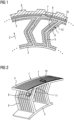
- the Figure 1 shows a partial section of the vehicle wheel according to the invention in a side view.
- the skeletal structure 1 of the vehicle wheel comprises an inner ring element 3 and an outer ring element 4, which are connected by a plurality of V-shaped suspension elements 5.
- the figure only shows a section of the vehicle wheel, which is constructed essentially rotationally symmetrically.
- the vehicle wheel continues rotationally symmetrically in both directions in the circumferential direction.
- a sensor 6, for example a strain sensor is arranged on one side of the suspension element 5. This strain sensor is connected to the suspension element 9 via a plug connection.
- a second sensor 7, for example a temperature sensor, is arranged on the top of the outer ring element 4. This sensor can be used, for example, to monitor the temperature of the tread 8.
- the suspension elements 5 and the outside of the outer ring element are reinforced via reinforcing elements 9 and 10.
- These reinforcing elements can be, for example, textile fibers, glass fibers or metal fibers. It is also conceivable that the reinforcing elements are designed in the form of reinforcement cords.
- the skeletal structure 1, the sensors 6 and 7 and the reinforcing elements 9 and 10 are completely covered by an elastomeric material.
- the tread 8 is connected, for example, to the outer ring 4 of the skeletal structure 1 via a high-strength adhesive.
- the Figure 2 shows schematically the partial section of the vehicle wheel in the Figure 1 in a three-dimensional view from diagonally above.
- the sensors 6 are attached directly to skeletal elements of the skeletal structure 1.
- the skeleton elements are reinforced in the manner shown by reinforcing elements 9 and 10.
- the reinforcing elements 9 and 10 can be designed, for example, in the form of textile fibers or metal fibers that span the skeleton element parallel to one another.
- a large number of cables 11 can also be integrated into the skeletal structure 1, which are connected to the sensors 6 and 7 and energy sources (not shown).
- the control unit with which the measurement signals from the sensors are recorded, can also be integrated into the skeletal structure of the vehicle wheel.
Landscapes
- Engineering & Computer Science (AREA)
- Mechanical Engineering (AREA)
- Vehicle Body Suspensions (AREA)
- Tires In General (AREA)
Description
- Die Erfindung betrifft ein Fahrzeugrad.
- Bei Luftreifen ist es bekannt, Sensoren im Reifen zu integrieren, um beispielsweise den Reifendruck zu überwachen. Diese sind jedoch als zusätzliche Bauteile im luftgefüllten Reifeninneren angeordnet und nicht integraler Bestandteil der Reifenstruktur, beispielsweise an oder auf den Festigkeitsträgern.
- Die
US 2019/351702 A1 ,WO 2019/227205 A1 ,US 2019/131687 A1 ,
JP 2021 024394 A US 2018/354304 A1 offenbaren bekannte Fahrzeugreifenkonstruktionen. - Der Erfindung lag die Aufgabe zugrunde, einen Fahrzeugrad bereitzustellen, bei dem Sensoren auf einfache Weise am Fahrzeugrad angeordnet werden können.
- Gelöst wird die Aufgabe durch Anspruch1.
- Ein Vorteil der Erfindung ist insbesondere darin zu sehen, dass der Sensor auf einfache Weise an der Skelett-Struktur des Fahrzeugrades angeordnet werden kann.
- An der Skelett-Struktur lassen sich beispielsweise einfache Halterungselemente für die zu montierenden Sensoren anordnen.
- Beim Zusammenbau des Fahrzeugrades werden die Sensoren direkt an den Halterungselementen befestigt. Danach kann dann die Ummantelung der Skelett-Struktur mit einem Elastomermaterial erfolgen.
- Außerdem können die Sensoren beispielsweise in Form eines Dehnungssensors an Positionen der Skelett-Struktur befestigt werden, die später für die Auswertung der Fahrdynamik des Fahrzeugrades besonders interessant sind.
- Erfindungsgemäß ist vorgesehen, dass der Sensor mit einer Steck-Verbindung mit einem Skelett-Element verbunden ist.
- Entsprechende Steckelemente lassen sich einfach an den Skelett-Elementen integrieren.
- Erfindungsgemäß umfasst die Steckverbindung Klipp-Verbindungen am Skelett-Element .
- In einer weiteren vorteilhaften Weiterbildung der Erfindung ist vorgesehen, dass der Sensor einen Dehnungssensor, Beschleunigungssensor und/oder Temperatursensor umfasst.
- Dadurch lassen sich wichtige Eigenschaften am Fahrzeugrad messen, die für die Fahrdynamik des Fahrzeugrades von Bedeutung sind.
- In einer weiteren vorteilhaften Weiterbildung der Erfindung ist vorgesehen, dass an der Skelett-Struktur weitere elektronische Bauteile in Form von Kabeln, Energiegeneratoren, Batterien und/ oder Aktuatoren integriert sind.
- Diese Bauteile lassen sich einfach an der Skelett-Struktur integrieren.
- In einer weiteren vorteilhaften Weiterbildung der Erfindung ist vorgesehen, dass die elektronischen Bauteile mit einer Verklebung an der Skelett-Struktur befestigt sind. Mit einer Verklebung lässt sich eine hochfeste Verbindung zwischen den beiden Bauteilen erzielen.
- Erfindungsgemäß umfasst die Skelett-Struktur ein inneres und einen äußeres Ringelement, die durch eine Vielzahl von Federungselementen verbunden sind.
- Dadurch lässt sich eine optimale Federung für das Fahrzeugrad erzielen.
- In einer weiteren vorteilhaften Weiterbildung der Erfindung ist vorgesehen, dass zumindest Bereiche der Federungselemente und/oder der Ringelemente mit Verstärkungselementen in Form von textilen Fasern, Glasfasern und/oder Metallfasern verstärkt sind.
- Dadurch lässt sich eine optimale Versteifung der Skelett-Elemente erzeugen.
- In einer weiteren vorteilhaften Weiterbildung der Erfindung ist vorgesehen, dass die Verstärkungselemente in Form einer Wicklung oder mit einem dreidimensionalen Druckverfahren an der Skelett-Struktur angeordnet sind.
- Dadurch lassen sich die Verstärkungselemente einfach an den Skelett-Elementen anordnen.
- In einer weiteren vorteilhaften Weiterbildung der Erfindung ist vorgesehen, dass die Skelettstruktur mit den elektronischen Sensoren und den Verstärkungselementen mit einem Elastomermaterial ummantelt ist. Dadurch wird die Skelett-Struktur und die elektronischen Sensoren effektiv vor mechanischen Beanspruchungen und vor Feuchtigkeit geschützt.
- In einer weiteren vorteilhaften Weiterbildung der Erfindung ist vorgesehen, dass die gesamte Skelettstruktur oder einzelne Skelett-Elemente mit einem dreidimensionalen Druckverfahren oder einem Spritzgussverfahren hergestellt werden.
- Dadurch wird die Herstellung der Skelett-Struktur wesentlich vereinfacht.
- In einer weiteren vorteilhaften Weiterbildung der Erfindung ist vorgesehen, dass die Skelettstruktur, die Verstärkungselemente und/ oder die elektronischen Bauteile vor dem Zusammenbau mit einem Haftvermittler ummantelt werden.
- Dadurch werden die Festigkeitseigenschaften zwischen den zu verbindenden Bauteilen wesentlich verbessert.
- Anhand eines Ausführungsbeispiels wird die Erfindung im Folgenden näher beschrieben.
- Es zeigen:
-
Fig. 1 : Einen Teilausschnitt eines Fahrzeugrades in einer Seitenansicht. -
Fig. 2 : Den Teilausschnitt des Fahrzeugrades in derFigur 1 in einer dreidimensionalen Ansicht von oben. - Die
Figur 1 zeigt einen Teilausschnitt des erfindungsgemäßen Fahrzeugrades in einer Seitenansicht. Die Skelett-Struktur 1 des Fahrzeugrades umfasst ein inneres Ringelement 3 und eines äußeres Ringelement 4, die durch eine Vielzahl von V-förmigen Federungselementen 5 verbunden sind. Die Figur zeigt lediglich einen Abschnitt des Fahrzeugrades, welches im Wesentlichen rotationssymmetrisch aufgebaut ist. Das Fahrzeugrad setzt sich in beide Richtungen in Umfangsrichtung rotationssymmetrisch fort. Auf einer Seite des Federungselementes 5 ist ein Sensor 6, beispielsweise ein Dehnungssensor, angeordnet. Dieser Dehnungssensor wird über eine Steckverbindung mit dem Federungselement 9 verbunden. Auf der Oberseite des äußeren Ringelementes 4 ist ein zweiter Sensor 7, beispielsweise ein Temperatursensor, angeordnet. Mit diesem Sensor lässt sich beispielsweise die Temperatur des Laufstreifens 8 überwachen. Die Federungselemente 5 und die Außenseite des äußeren Ringelementes sind über Verstärkungselemente 9 und 10 verstärkt. Bei diesen Verstärkungselementen kann es sich beispielsweise um textile Fasern, Glasfasern oder Metallfasern handeln. Es ist ebenfalls denkbar, dass die Verstärkungselemente in Form von Festigkeitsträgerkorden ausgestaltet sind. Die Skelett-Struktur 1, die Sensoren 6 und 7 und die Verstärkungselemente 9 und 10 werden vollständig durch ein Elastomermaterial ummantelt. Der Laufstreifen 8 wird beispielsweise über eine hochfeste Verklebung mit dem äußeren Ring 4 der Skelett-Struktur 1 verbunden. - Die
Figur 2 zeigt schematisch den Teilausschnitt des Fahrzeugrades in derFigur 1 in einer dreidimensionalen Ansicht von schräg oben. Die Sensoren 6 sind direkt an Skelett-Elementen der Skelett-Struktur 1 befestigt. Die Skelett-Elemente werden in der dargestellten Weise durch Verstärkungselemente 9 und 10 verstärkt. Die Verstärkungselemente 9 und 10 können beispielsweise in Form von Textilfasern oder Metallfasern ausgebildet sein, die parallel zueinander das Skelett-Element überspannen. - An der Skelett-Struktur 1 können außerdem eine Vielzahl von Kabel 11 integriert werden, die mit den Sensoren 6 und 7 und nicht dargestellten Energiequellen verbunden werden.
- Die Steuerungseinheit, mit der die Messsignale der Sensoren erfasst werden, kann ebenfalls in der Skelett-Struktur des Fahrzeugrades integriert werden.
-
- 1
- Skelettstruktur
- 2
- Radiale Richtung des Fahrzeugreifens
- 3
- Inneres Ringelement (Skelettelement)
- 4
- Äußeres Ringelement (Skelettelement)
- 5
- V-förmiges Federungselement der Skelettstruktur
- 6
- Dehnungssensor am Federungselement
- 7
- Temperatursensor unterhalb des Laufstreifens
- 8
- Laufstreifen
- 9
- Verstärkungselement an Federungselement
- 10
- Verstärkungselement an äußeren Ringelement
- 11
- Kabel
- 12
- Ummantelung mit Elastomermaterial
Claims (7)
- Fahrzeugrad mit einem Laufstreifen (8),wobei der Laufstreifen (8) auf der Außenseite eines Ringelementes (4) angeordnet ist und das Fahrzeugrad eine Vielzahl von Federungselementen (5) aufweist,das Fahrzeugrad eine Skelettstruktur (1) aufweist und an mindestens einem Skelett-Element (4,5) der Skelettstruktur (1) ein elektronischer Sensor (6,7) angeordnet ist,wobei die Skelett-Struktur (1) ein inneres und ein äußeres Ringelement (3,4)umfasst, die durch die Vielzahl von Federungselementen (5) verbunden sind, dadurch gekennzeichnet, dassder elektronische Sensor (6,7) mit einer Steckverbindung mit einem Skelett-Element (4,5) verbunden ist, wobei die Steckverbindung einzelne Klipp-Verbindungen am Skelett-Element (1) umfassen.
- Fahrzeugrad nach Anspruch 1,
dadurch gekennzeichnet, dass
der Sensor (6,7) einen Dehnungssensor, Beschleunigungssensor und/oder Temperatursensor umfasst. - Fahrzeugrad nach einem der vorhergehenden Ansprüche,
dadurch gekennzeichnet, dass
an der Skelett-Struktur (1) weitere elektronische Bauteile in Form von Kabeln, Energiegeneratoren, Batterien und/ oder Aktuatoren integriert sind. - Fahrzeugrad nach Anspruch 3,
dadurch gekennzeichnet, dass
die weiteren elektronischen Bauteile mit einer Verklebung an der Skelett-Struktur befestigt sind. - Fahrzeugrad nach einem der vorhergehenden Ansprüche,
dadurch gekennzeichnet, dass
zumindestens Bereiche der Federungselemente (5) und/oder der Ringelemente (3,4) mit Verstärkungselementen (9,10) in Form von textilen Fasern, Glasfasern und/oder Metallfasern verstärkt sind. - Fahrzeugrad nach Anspruch 5,
dadurch gekennzeichnet, dass
die Verstärkungselemente (9,10) in Form einer Wicklung oder mit einem dreidimensionalen Druckverfahren an der Skelett-Struktur (1) angeordnet sind. - Fahrzeugrad nach Anspruch 5,
dadurch gekennzeichnet, dass
die Skelettstruktur (1) mit den elektronischen Sensoren (6,7) und den Verstärkungselementen (9,10) mit einem Elastomermaterial (12) ummantelt ist.
Applications Claiming Priority (1)
| Application Number | Priority Date | Filing Date | Title |
|---|---|---|---|
| DE102021201824.6A DE102021201824A1 (de) | 2021-02-26 | 2021-02-26 | Fahrzeugrad |
Publications (3)
| Publication Number | Publication Date |
|---|---|
| EP4049858A1 EP4049858A1 (de) | 2022-08-31 |
| EP4049858B1 true EP4049858B1 (de) | 2024-02-21 |
| EP4049858B8 EP4049858B8 (de) | 2024-03-27 |
Family
ID=78820302
Family Applications (1)
| Application Number | Title | Priority Date | Filing Date |
|---|---|---|---|
| EP21211784.0A Active EP4049858B8 (de) | 2021-02-26 | 2021-12-01 | Fahrzeugrad |
Country Status (2)
| Country | Link |
|---|---|
| EP (1) | EP4049858B8 (de) |
| DE (1) | DE102021201824A1 (de) |
Family Cites Families (10)
| Publication number | Priority date | Publication date | Assignee | Title |
|---|---|---|---|---|
| JP4674253B2 (ja) * | 2008-11-28 | 2011-04-20 | 東洋ゴム工業株式会社 | 非空気圧タイヤ |
| WO2017116825A1 (en) * | 2015-12-29 | 2017-07-06 | Bridgestone Americas Tire Operations, Llc | Composite layer tire |
| JP2018083458A (ja) * | 2016-11-21 | 2018-05-31 | 株式会社ブリヂストン | 非空気入りタイヤおよび二輪車 |
| US10749242B2 (en) * | 2017-10-30 | 2020-08-18 | The Goodyear Tire & Rubber Company | Non-pneumatic tire with radio frequency identification |
| DE102018200556A1 (de) * | 2018-01-15 | 2019-07-18 | Continental Reifen Deutschland Gmbh | Verfahren zur Herstellung eines Transponders für einen Fahrzeugreifen |
| WO2019227205A1 (en) * | 2018-05-28 | 2019-12-05 | Camso Inc. | Wheel comprising a non-pneumatic tire |
| JP7393892B2 (ja) * | 2019-08-02 | 2023-12-07 | Toyo Tire株式会社 | 非空気圧タイヤおよび状態評価方法 |
| CN111114204A (zh) * | 2020-01-20 | 2020-05-08 | 季华实验室 | 支撑体、非充气轮胎及其制造方法、弹性支撑部制造方法 |
| CN111546838B (zh) * | 2020-04-19 | 2021-12-14 | 季华实验室 | 轮辐支撑体组件、非充气轮胎的转速感应装置及估算方法 |
| CN111532089B (zh) * | 2020-04-19 | 2021-04-20 | 季华实验室 | 非充气轮胎的垂向力感应装置、估算系统及估算方法 |
-
2021
- 2021-02-26 DE DE102021201824.6A patent/DE102021201824A1/de not_active Withdrawn
- 2021-12-01 EP EP21211784.0A patent/EP4049858B8/de active Active
Also Published As
| Publication number | Publication date |
|---|---|
| EP4049858B8 (de) | 2024-03-27 |
| EP4049858A1 (de) | 2022-08-31 |
| DE102021201824A1 (de) | 2022-09-01 |
Similar Documents
| Publication | Publication Date | Title |
|---|---|---|
| EP1858715B1 (de) | Fahrzeugrad | |
| DE102007001279B4 (de) | Fahrzeugluftreifen mit einem Elektronikmodul | |
| DE69917185T2 (de) | Lose Überwachungsvorrichtung für Reifen | |
| DE102016224638B4 (de) | Untersetzungsgetriebe für elektrische Servolenkvorrichtung | |
| EP1565331A1 (de) | Haltevorrichtung zur befestigung eines elektronischen bauteils | |
| EP2080685B1 (de) | Drehmomentsensierung mittels integrierter Dehnungsmessstreifen | |
| EP3634782B1 (de) | Fahrzeugreifen | |
| DE102013003428A1 (de) | Schneckenrad für eine elektrische Servolenkungsvorrichtung und Verfahren zur Herstellung desselben | |
| EP1370842B1 (de) | Torsionsmodul einer drehmomenterfassungseinrichtung | |
| DE102010035940A1 (de) | Überwachungs- und Notfallsystem für Kraftfahrzeuge | |
| EP4049858B1 (de) | Fahrzeugrad | |
| DE69920175T2 (de) | Lenkradskelett mit angesetztem oder integriertem drehmomentsensor für eine fahrzeuglenkung | |
| DE102016216448A1 (de) | Lenksäule für Fahrzeuge | |
| WO2008012300A1 (de) | Antenne in einem faserverstärkten verbundwerkstoff und verfahren zur ausbildung einer antenne in einem faserverstärkten verbundwerkstoff | |
| EP3450200A1 (de) | Radnabenübertragungseinheit für eine radnabe eines fahrzeugs, radnabe und hilfsangetriebenes fahrzeug | |
| DE102005061506A1 (de) | Strukturteil für ein Fahrzeug | |
| DE102010052916B4 (de) | Laufrad eines Fahrrades mit Dehnungsmessstreifen und/oder LED-Anzeige sowie Fahrrad | |
| DE102010017851A1 (de) | Torsionsmodul | |
| EP4052892A2 (de) | Verfahren zur herstellung eines fahrzeugreifens | |
| DE102015006652A1 (de) | Fahrzeugrad sowie Verfahren zur Herstellung eines Fahrzeugrads | |
| EP0935129B1 (de) | Mehrkomponenten-Messrad | |
| EP3540248B1 (de) | Anordnung zur schwingungsisolierung bowdenzugbetätigter komponenten | |
| DE102012105154A1 (de) | Hilfsrahmen | |
| DE102005027104B4 (de) | Fahrzeugreifen | |
| DE102016215584A1 (de) | Fahrzeugreifen mit einem Reifensensor |
Legal Events
| Date | Code | Title | Description |
|---|---|---|---|
| PUAI | Public reference made under article 153(3) epc to a published international application that has entered the european phase |
Free format text: ORIGINAL CODE: 0009012 |
|
| STAA | Information on the status of an ep patent application or granted ep patent |
Free format text: STATUS: THE APPLICATION HAS BEEN PUBLISHED |
|
| AK | Designated contracting states |
Kind code of ref document: A1 Designated state(s): AL AT BE BG CH CY CZ DE DK EE ES FI FR GB GR HR HU IE IS IT LI LT LU LV MC MK MT NL NO PL PT RO RS SE SI SK SM TR |
|
| STAA | Information on the status of an ep patent application or granted ep patent |
Free format text: STATUS: REQUEST FOR EXAMINATION WAS MADE |
|
| 17P | Request for examination filed |
Effective date: 20230228 |
|
| RBV | Designated contracting states (corrected) |
Designated state(s): AL AT BE BG CH CY CZ DE DK EE ES FI FR GB GR HR HU IE IS IT LI LT LU LV MC MK MT NL NO PL PT RO RS SE SI SK SM TR |
|
| GRAP | Despatch of communication of intention to grant a patent |
Free format text: ORIGINAL CODE: EPIDOSNIGR1 |
|
| STAA | Information on the status of an ep patent application or granted ep patent |
Free format text: STATUS: GRANT OF PATENT IS INTENDED |
|
| INTG | Intention to grant announced |
Effective date: 20231026 |
|
| GRAS | Grant fee paid |
Free format text: ORIGINAL CODE: EPIDOSNIGR3 |
|
| GRAA | (expected) grant |
Free format text: ORIGINAL CODE: 0009210 |
|
| STAA | Information on the status of an ep patent application or granted ep patent |
Free format text: STATUS: THE PATENT HAS BEEN GRANTED |
|
| P01 | Opt-out of the competence of the unified patent court (upc) registered |
Effective date: 20231220 |
|
| REG | Reference to a national code |
Ref country code: DE Ref legal event code: R081 Ref document number: 502021002756 Country of ref document: DE Owner name: CONTINENTAL REIFEN DEUTSCHLAND GMBH, DE Free format text: FORMER OWNER: CONTINENTAL REIFEN DEUTSCHLAND GMBH, 30173 HANNOVER, DE |
|
| AK | Designated contracting states |
Kind code of ref document: B1 Designated state(s): AL AT BE BG CH CY CZ DE DK EE ES FI FR GB GR HR HU IE IS IT LI LT LU LV MC MK MT NL NO PL PT RO RS SE SI SK SM TR |
|
| REG | Reference to a national code |
Ref country code: GB Ref legal event code: FG4D Free format text: NOT ENGLISH |
|
| REG | Reference to a national code |
Ref country code: CH Ref legal event code: PK Free format text: BERICHTIGUNG B8 Ref country code: CH Ref legal event code: EP |
|
| RAP4 | Party data changed (patent owner data changed or rights of a patent transferred) |
Owner name: CONTINENTAL REIFEN DEUTSCHLAND GMBH |
|
| REG | Reference to a national code |
Ref country code: IE Ref legal event code: FG4D Free format text: LANGUAGE OF EP DOCUMENT: GERMAN |
|
| REG | Reference to a national code |
Ref country code: DE Ref legal event code: R096 Ref document number: 502021002756 Country of ref document: DE |
|
| REG | Reference to a national code |
Ref country code: LT Ref legal event code: MG9D |
|
| REG | Reference to a national code |
Ref country code: NL Ref legal event code: MP Effective date: 20240221 |
|
| PG25 | Lapsed in a contracting state [announced via postgrant information from national office to epo] |
Ref country code: IS Free format text: LAPSE BECAUSE OF FAILURE TO SUBMIT A TRANSLATION OF THE DESCRIPTION OR TO PAY THE FEE WITHIN THE PRESCRIBED TIME-LIMIT Effective date: 20240621 |
|
| PG25 | Lapsed in a contracting state [announced via postgrant information from national office to epo] |
Ref country code: LT Free format text: LAPSE BECAUSE OF FAILURE TO SUBMIT A TRANSLATION OF THE DESCRIPTION OR TO PAY THE FEE WITHIN THE PRESCRIBED TIME-LIMIT Effective date: 20240221 |
|
| PG25 | Lapsed in a contracting state [announced via postgrant information from national office to epo] |
Ref country code: GR Free format text: LAPSE BECAUSE OF FAILURE TO SUBMIT A TRANSLATION OF THE DESCRIPTION OR TO PAY THE FEE WITHIN THE PRESCRIBED TIME-LIMIT Effective date: 20240522 |
|
| PG25 | Lapsed in a contracting state [announced via postgrant information from national office to epo] |
Ref country code: HR Free format text: LAPSE BECAUSE OF FAILURE TO SUBMIT A TRANSLATION OF THE DESCRIPTION OR TO PAY THE FEE WITHIN THE PRESCRIBED TIME-LIMIT Effective date: 20240221 Ref country code: RS Free format text: LAPSE BECAUSE OF FAILURE TO SUBMIT A TRANSLATION OF THE DESCRIPTION OR TO PAY THE FEE WITHIN THE PRESCRIBED TIME-LIMIT Effective date: 20240521 Ref country code: NL Free format text: LAPSE BECAUSE OF FAILURE TO SUBMIT A TRANSLATION OF THE DESCRIPTION OR TO PAY THE FEE WITHIN THE PRESCRIBED TIME-LIMIT Effective date: 20240221 |
|
| PG25 | Lapsed in a contracting state [announced via postgrant information from national office to epo] |
Ref country code: ES Free format text: LAPSE BECAUSE OF FAILURE TO SUBMIT A TRANSLATION OF THE DESCRIPTION OR TO PAY THE FEE WITHIN THE PRESCRIBED TIME-LIMIT Effective date: 20240221 |
|
| PG25 | Lapsed in a contracting state [announced via postgrant information from national office to epo] |
Ref country code: RS Free format text: LAPSE BECAUSE OF FAILURE TO SUBMIT A TRANSLATION OF THE DESCRIPTION OR TO PAY THE FEE WITHIN THE PRESCRIBED TIME-LIMIT Effective date: 20240521 Ref country code: NO Free format text: LAPSE BECAUSE OF FAILURE TO SUBMIT A TRANSLATION OF THE DESCRIPTION OR TO PAY THE FEE WITHIN THE PRESCRIBED TIME-LIMIT Effective date: 20240521 Ref country code: NL Free format text: LAPSE BECAUSE OF FAILURE TO SUBMIT A TRANSLATION OF THE DESCRIPTION OR TO PAY THE FEE WITHIN THE PRESCRIBED TIME-LIMIT Effective date: 20240221 Ref country code: LT Free format text: LAPSE BECAUSE OF FAILURE TO SUBMIT A TRANSLATION OF THE DESCRIPTION OR TO PAY THE FEE WITHIN THE PRESCRIBED TIME-LIMIT Effective date: 20240221 Ref country code: IS Free format text: LAPSE BECAUSE OF FAILURE TO SUBMIT A TRANSLATION OF THE DESCRIPTION OR TO PAY THE FEE WITHIN THE PRESCRIBED TIME-LIMIT Effective date: 20240621 Ref country code: HR Free format text: LAPSE BECAUSE OF FAILURE TO SUBMIT A TRANSLATION OF THE DESCRIPTION OR TO PAY THE FEE WITHIN THE PRESCRIBED TIME-LIMIT Effective date: 20240221 Ref country code: GR Free format text: LAPSE BECAUSE OF FAILURE TO SUBMIT A TRANSLATION OF THE DESCRIPTION OR TO PAY THE FEE WITHIN THE PRESCRIBED TIME-LIMIT Effective date: 20240522 Ref country code: FI Free format text: LAPSE BECAUSE OF FAILURE TO SUBMIT A TRANSLATION OF THE DESCRIPTION OR TO PAY THE FEE WITHIN THE PRESCRIBED TIME-LIMIT Effective date: 20240221 Ref country code: ES Free format text: LAPSE BECAUSE OF FAILURE TO SUBMIT A TRANSLATION OF THE DESCRIPTION OR TO PAY THE FEE WITHIN THE PRESCRIBED TIME-LIMIT Effective date: 20240221 Ref country code: BG Free format text: LAPSE BECAUSE OF FAILURE TO SUBMIT A TRANSLATION OF THE DESCRIPTION OR TO PAY THE FEE WITHIN THE PRESCRIBED TIME-LIMIT Effective date: 20240221 |
|
| PG25 | Lapsed in a contracting state [announced via postgrant information from national office to epo] |
Ref country code: PL Free format text: LAPSE BECAUSE OF FAILURE TO SUBMIT A TRANSLATION OF THE DESCRIPTION OR TO PAY THE FEE WITHIN THE PRESCRIBED TIME-LIMIT Effective date: 20240221 Ref country code: PT Free format text: LAPSE BECAUSE OF FAILURE TO SUBMIT A TRANSLATION OF THE DESCRIPTION OR TO PAY THE FEE WITHIN THE PRESCRIBED TIME-LIMIT Effective date: 20240621 |
|
| PG25 | Lapsed in a contracting state [announced via postgrant information from national office to epo] |
Ref country code: SE Free format text: LAPSE BECAUSE OF FAILURE TO SUBMIT A TRANSLATION OF THE DESCRIPTION OR TO PAY THE FEE WITHIN THE PRESCRIBED TIME-LIMIT Effective date: 20240221 Ref country code: PT Free format text: LAPSE BECAUSE OF FAILURE TO SUBMIT A TRANSLATION OF THE DESCRIPTION OR TO PAY THE FEE WITHIN THE PRESCRIBED TIME-LIMIT Effective date: 20240621 Ref country code: PL Free format text: LAPSE BECAUSE OF FAILURE TO SUBMIT A TRANSLATION OF THE DESCRIPTION OR TO PAY THE FEE WITHIN THE PRESCRIBED TIME-LIMIT Effective date: 20240221 Ref country code: LV Free format text: LAPSE BECAUSE OF FAILURE TO SUBMIT A TRANSLATION OF THE DESCRIPTION OR TO PAY THE FEE WITHIN THE PRESCRIBED TIME-LIMIT Effective date: 20240221 |
|
| PG25 | Lapsed in a contracting state [announced via postgrant information from national office to epo] |
Ref country code: DK Free format text: LAPSE BECAUSE OF FAILURE TO SUBMIT A TRANSLATION OF THE DESCRIPTION OR TO PAY THE FEE WITHIN THE PRESCRIBED TIME-LIMIT Effective date: 20240221 |
|
| PG25 | Lapsed in a contracting state [announced via postgrant information from national office to epo] |
Ref country code: SM Free format text: LAPSE BECAUSE OF FAILURE TO SUBMIT A TRANSLATION OF THE DESCRIPTION OR TO PAY THE FEE WITHIN THE PRESCRIBED TIME-LIMIT Effective date: 20240221 |
|
| PG25 | Lapsed in a contracting state [announced via postgrant information from national office to epo] |
Ref country code: CZ Free format text: LAPSE BECAUSE OF FAILURE TO SUBMIT A TRANSLATION OF THE DESCRIPTION OR TO PAY THE FEE WITHIN THE PRESCRIBED TIME-LIMIT Effective date: 20240221 Ref country code: EE Free format text: LAPSE BECAUSE OF FAILURE TO SUBMIT A TRANSLATION OF THE DESCRIPTION OR TO PAY THE FEE WITHIN THE PRESCRIBED TIME-LIMIT Effective date: 20240221 |
|
| PG25 | Lapsed in a contracting state [announced via postgrant information from national office to epo] |
Ref country code: SK Free format text: LAPSE BECAUSE OF FAILURE TO SUBMIT A TRANSLATION OF THE DESCRIPTION OR TO PAY THE FEE WITHIN THE PRESCRIBED TIME-LIMIT Effective date: 20240221 |
|
| PG25 | Lapsed in a contracting state [announced via postgrant information from national office to epo] |
Ref country code: SM Free format text: LAPSE BECAUSE OF FAILURE TO SUBMIT A TRANSLATION OF THE DESCRIPTION OR TO PAY THE FEE WITHIN THE PRESCRIBED TIME-LIMIT Effective date: 20240221 Ref country code: SK Free format text: LAPSE BECAUSE OF FAILURE TO SUBMIT A TRANSLATION OF THE DESCRIPTION OR TO PAY THE FEE WITHIN THE PRESCRIBED TIME-LIMIT Effective date: 20240221 Ref country code: RO Free format text: LAPSE BECAUSE OF FAILURE TO SUBMIT A TRANSLATION OF THE DESCRIPTION OR TO PAY THE FEE WITHIN THE PRESCRIBED TIME-LIMIT Effective date: 20240221 Ref country code: EE Free format text: LAPSE BECAUSE OF FAILURE TO SUBMIT A TRANSLATION OF THE DESCRIPTION OR TO PAY THE FEE WITHIN THE PRESCRIBED TIME-LIMIT Effective date: 20240221 Ref country code: DK Free format text: LAPSE BECAUSE OF FAILURE TO SUBMIT A TRANSLATION OF THE DESCRIPTION OR TO PAY THE FEE WITHIN THE PRESCRIBED TIME-LIMIT Effective date: 20240221 Ref country code: CZ Free format text: LAPSE BECAUSE OF FAILURE TO SUBMIT A TRANSLATION OF THE DESCRIPTION OR TO PAY THE FEE WITHIN THE PRESCRIBED TIME-LIMIT Effective date: 20240221 |
|
| REG | Reference to a national code |
Ref country code: DE Ref legal event code: R097 Ref document number: 502021002756 Country of ref document: DE |
|
| PG25 | Lapsed in a contracting state [announced via postgrant information from national office to epo] |
Ref country code: IT Free format text: LAPSE BECAUSE OF FAILURE TO SUBMIT A TRANSLATION OF THE DESCRIPTION OR TO PAY THE FEE WITHIN THE PRESCRIBED TIME-LIMIT Effective date: 20240221 |
|
| PLBE | No opposition filed within time limit |
Free format text: ORIGINAL CODE: 0009261 |
|
| STAA | Information on the status of an ep patent application or granted ep patent |
Free format text: STATUS: NO OPPOSITION FILED WITHIN TIME LIMIT |
|
| PG25 | Lapsed in a contracting state [announced via postgrant information from national office to epo] |
Ref country code: IT Free format text: LAPSE BECAUSE OF FAILURE TO SUBMIT A TRANSLATION OF THE DESCRIPTION OR TO PAY THE FEE WITHIN THE PRESCRIBED TIME-LIMIT Effective date: 20240221 |
|
| 26N | No opposition filed |
Effective date: 20241122 |
|
| PG25 | Lapsed in a contracting state [announced via postgrant information from national office to epo] |
Ref country code: SI Free format text: LAPSE BECAUSE OF FAILURE TO SUBMIT A TRANSLATION OF THE DESCRIPTION OR TO PAY THE FEE WITHIN THE PRESCRIBED TIME-LIMIT Effective date: 20240221 |
|
| PG25 | Lapsed in a contracting state [announced via postgrant information from national office to epo] |
Ref country code: MC Free format text: LAPSE BECAUSE OF FAILURE TO SUBMIT A TRANSLATION OF THE DESCRIPTION OR TO PAY THE FEE WITHIN THE PRESCRIBED TIME-LIMIT Effective date: 20240221 |
|
| REG | Reference to a national code |
Ref country code: CH Ref legal event code: PL |
|
| PG25 | Lapsed in a contracting state [announced via postgrant information from national office to epo] |
Ref country code: LU Free format text: LAPSE BECAUSE OF NON-PAYMENT OF DUE FEES Effective date: 20241201 |
|
| REG | Reference to a national code |
Ref country code: BE Ref legal event code: MM Effective date: 20241231 |
|
| PG25 | Lapsed in a contracting state [announced via postgrant information from national office to epo] |
Ref country code: BE Free format text: LAPSE BECAUSE OF NON-PAYMENT OF DUE FEES Effective date: 20241231 |
|
| PG25 | Lapsed in a contracting state [announced via postgrant information from national office to epo] |
Ref country code: CH Free format text: LAPSE BECAUSE OF NON-PAYMENT OF DUE FEES Effective date: 20241231 |
|
| PG25 | Lapsed in a contracting state [announced via postgrant information from national office to epo] |
Ref country code: IE Free format text: LAPSE BECAUSE OF NON-PAYMENT OF DUE FEES Effective date: 20241201 |
|
| PGFP | Annual fee paid to national office [announced via postgrant information from national office to epo] |
Ref country code: AT Payment date: 20260113 Year of fee payment: 5 |
|
| PGFP | Annual fee paid to national office [announced via postgrant information from national office to epo] |
Ref country code: FR Payment date: 20251229 Year of fee payment: 5 |
|
| PG25 | Lapsed in a contracting state [announced via postgrant information from national office to epo] |
Ref country code: CY Free format text: LAPSE BECAUSE OF FAILURE TO SUBMIT A TRANSLATION OF THE DESCRIPTION OR TO PAY THE FEE WITHIN THE PRESCRIBED TIME-LIMIT; INVALID AB INITIO Effective date: 20211201 |
|
| PGFP | Annual fee paid to national office [announced via postgrant information from national office to epo] |
Ref country code: DE Payment date: 20251231 Year of fee payment: 5 |