EP4049836A1 - Tape arranging device - Google Patents
Tape arranging device Download PDFInfo
- Publication number
- EP4049836A1 EP4049836A1 EP22157873.5A EP22157873A EP4049836A1 EP 4049836 A1 EP4049836 A1 EP 4049836A1 EP 22157873 A EP22157873 A EP 22157873A EP 4049836 A1 EP4049836 A1 EP 4049836A1
- Authority
- EP
- European Patent Office
- Prior art keywords
- guide roller
- tape
- support portion
- roller units
- end portion
- Prior art date
- Legal status (The legal status is an assumption and is not a legal conclusion. Google has not performed a legal analysis and makes no representation as to the accuracy of the status listed.)
- Granted
Links
Images



Classifications
-
- B—PERFORMING OPERATIONS; TRANSPORTING
- B29—WORKING OF PLASTICS; WORKING OF SUBSTANCES IN A PLASTIC STATE IN GENERAL
- B29C—SHAPING OR JOINING OF PLASTICS; SHAPING OF MATERIAL IN A PLASTIC STATE, NOT OTHERWISE PROVIDED FOR; AFTER-TREATMENT OF THE SHAPED PRODUCTS, e.g. REPAIRING
- B29C70/00—Shaping composites, i.e. plastics material comprising reinforcements, fillers or preformed parts, e.g. inserts
- B29C70/04—Shaping composites, i.e. plastics material comprising reinforcements, fillers or preformed parts, e.g. inserts comprising reinforcements only, e.g. self-reinforcing plastics
- B29C70/28—Shaping operations therefor
- B29C70/30—Shaping by lay-up, i.e. applying fibres, tape or broadsheet on a mould, former or core; Shaping by spray-up, i.e. spraying of fibres on a mould, former or core
- B29C70/38—Automated lay-up, e.g. using robots, laying filaments according to predetermined patterns
- B29C70/386—Automated tape laying [ATL]
- B29C70/388—Tape placement heads, e.g. component parts, details or accessories
Definitions
- the present disclosure relates to a tape arranging device for arranging tape materials.
- a composite material in which a resin (plastic) is combined with a fiber (fiber reinforced plastics (FRP)) is a material excellent in specific strength and specific rigidity. Therefore, the composite material is used as structural materials and the like in the fields of automobiles, aircrafts, and space.
- the composite material is produced by laminating prepregs, fibers impregnated with a resin, to form a laminate, and then hardening the resin as disclosed, for example, in Japanese Unexamined Patent Application Publication ( JP-A) No. 2011-093276 .
- AFP automated fiber placement
- the present disclosure relates to a tape arranging device.
- the tape arranging device includes guide roller units and a moving unit. Tape materials are capable of passing through the respective guide roller units. Each of the tape materials are configured with fibers impregnated with resin.
- the moving unit is configured to move the guide roller units and to change a distance between adjacent ones of the guide roller units. The adjacent ones of the guide roller units are adjacent to each other.
- a distance between center lines of adjacent tape materials is referred to as a "tape pitch" in a sheet configured with the tape materials arranged without a gap.
- a width of the tape material itself may also be changed. Therefore, it is desired to develop a technique of arranging tape materials without a gap even when the width of the tape material is changed.
- the present disclosure relates to a tape arranging device capable of arranging tape materials at any tape pitch.
- FIG. 1 is a diagram illustrating a composite material manufacturing apparatus 100 according to the embodiments.
- the composite material manufacturing apparatus 100 includes a feeding device 110, heating devices 120, width adjusting devices 130, a tape arranging device 140, and a central control unit 150.
- an X axis, a Y axis, and a Z axis which perpendicular to each other are defined as shown with respect to the tape arranging device 140.
- a broken line arrow indicates a feeding direction of a tape material T by the feeding device 110.
- the feeding device 110 sends out the tape material T supplied from a stock roller or the like around which the tape material T is wound. In the embodiments, the feeding device 110 sends out seven tape materials T, but the number of tape materials T is not limited to seven.
- the tape material T is configured with prepregs. Prepregs are fibers impregnated with resin.
- the prepreg is used as a material of FRP (a composite material) such as CFRP or GFRP.
- the fibers configuring the tape material T are, for example, any one or more of carbon fibers, glass fibers, boron fibers, aramid fibers, and polyarylate fibers.
- Polyarylate fibers includes, for example, Vectran, which is a registered trademark.
- the resin configuring the tape material T is a thermosetting resin or a thermoplastic resin.
- thermosetting resin is, for example, any one or more of phenol resin (PF), epoxy resin (EP), melamine resin (MF), urea resin (UF), unsaturated polyester resin (UP), alkyd resin, polyurethane (PUR), thermosetting polyimide (PI), benzoxazine, and polybismaleimide (BMI).
- PF phenol resin
- EP epoxy resin
- MF melamine resin
- UF urea resin
- UP unsaturated polyester resin
- PUR thermosetting polyimide
- PI benzoxazine
- BMI polybismaleimide
- the thermoplastic resin is, for example, any one or more of polyphenylene sulfide (PPS), pre-tetrafluoroethylene, polysulfone (PSF), polyether sulfone (PES), amorphous polyarylate (PAR), liquid crystal polymer (LCP), polyether ether ketone (PEEK), thermoplastic polyimide (PI), polyamide imide (PAI), polyamide (PA), nylon, polyacetal (POM), polycarbonate (PC), modified polyphenylene ether (modified PPE), polyethylene terephthalate (PET), polybutylene terephthalate (PBT), cyclic polyolefin (COP), polyethylene (PE), polypropylene (PP), polyvinyl chloride (PVC), polyvinylidene chloride, polystyrene (PS), polyvinyl acetate (PVAc), polyurethane (PUR), ABS resin, AS resin, acrylic resin (PMMA), and polyetherketone ketone (PE
- the feeding device 110 includes a compaction roller 112, downstream support rollers 114a and 114b, and upstream support rollers 116a and 116b.
- the compaction roller 112, the downstream support rollers 114a and 114b, and the upstream support rollers 116a and 116b each have a cylindrical shape.
- the compaction roller 112, the downstream support rollers 114a and 114b, and the upstream support rollers 116a and 116b are arranged such that rotation axes thereof are in an X-axis direction in FIG. 1 .
- the compaction roller 112 the downstream support rollers 114a and 114b, and the upstream support rollers 116a and 116b are provided at different positions in a flow direction of the tape material T.
- the compaction roller 112 is provided downstream of the downstream support rollers 114a and 114b in the feeding direction of the tape material T.
- the downstream support rollers 114a and 114b are provided downstream of the upstream support rollers 116a and 116b in the feeding direction of the tape material T. That is, the upstream support rollers 116a and 116b, the downstream support rollers 114a and 114b, and the compaction roller 112 are provided in this order from an upstream side in the feeding direction of the tape material T.
- downstream support roller 114a and the downstream support roller 114b are provided to be different in positions in a Y-axis direction and a Z-axis direction in FIG. 1 . Further, the upstream support roller 116a and the upstream support roller 116b are provided to be different in positions in the Y-axis direction in FIG. 1 .
- the compaction roller 112 is moved while being pressed against a mold, and thereby the compaction roller 112 is passively rotated due to an adhesive force or a frictional force of the tape material T.
- the tape materials T are stretched between the downstream support rollers 114a and 114b, and between the upstream support rollers 116a and 116b.
- Four tape materials T are stretched between the downstream support roller 114a and the upstream support roller 116a.
- Three tape materials T are stretched between the downstream support roller 114b and the upstream support roller 116b.
- the downstream support rollers 114a and 114b and the upstream support rollers 116a and 116b change directions of the tape materials T such that each of the tape materials T vertically passes through an inside of the tape arranging device 140.
- the downstream support rollers 114a and 114b and the upstream support rollers 116a and 116b are rotated due to a frictional force or an adhesive force when the tape material T is sent out for lamination.
- the heating devices 120 heats the tape materials T.
- the heating devices 120 are implemented by, for example, an electric heater, a heat exchanger, or a warm air blower.
- the heating devices 120 are provided upstream of the width adjusting device 130 in the feeding direction of the tape material T.
- the width adjusting devices 130 are provided between the heating device 120 and the upstream support rollers 116a and 116b.
- the width adjusting devices 130 are fixed to a mount (not shown).
- the width adjusting device 130 changes, in response to a control command from the central control unit 150 to be described later, the width of the tape material T that has passed through the heating device 120.
- the number of width adjustment devices 130 corresponding to the number of the tape materials T are provided, and each of the width adjusting device 130 changes a width of one tape material T. In this case, seven adjustment devices are provided.
- each of the width adjusting devices 130 changes the width of the tape material T to substantially the same width.
- the width adjusting device 130 includes a main body which is formed by a bottom surface and a pair of wall surfaces whose interval gradually decreases and which has a path through which the tape material T passes.
- the width adjusting device 130 may include various techniques such as a technique of changing the interval between the wall surfaces at an outlet of the tape material in the path by changing a rotation angle of the main body, and a detailed description of the various techniques will be omitted here.
- the width adjusting devices 130 adjust the widths of the respective tape materials T based on a tape width (tape pitch) of a sheet configured with the tape materials T that are sent out from the compaction roller 112 and arranged without a gap.
- the tape materials T whose widths have been changed by the width adjusting devices 130 pass through the upstream support roller 116a and the upstream support roller 116b, and then the tape materials T are arranged without gaps by the tape arranging device 140. After that, the tape materials T pass through the downstream support rollers 114a and 114b and the compaction roller 112, then are laminated on a mold, are maintained at a predetermined temperature, and are formed into a composite material.
- the tape arranging device 140 will be described in detail later.
- the central control unit 150 is configured with a semiconductor integrated circuit including a central processing unit (CPU).
- the central control unit 150 reads, from the ROM, programs, parameters, and the like for operating the CPU.
- the central control unit 150 manages and controls the entire composite material manufacturing apparatus 100 in cooperation with a RAM serving as a work area and other electronic circuits.
- the central control unit 150 controls the width adjusting devices 130 and a link unit 260 (drive unit) of the tape arranging device 140 to be described later.
- the tape arranging device 140 arranges the tape materials T, the widths of which have been changed by the width adjusting devices 130, without gaps.
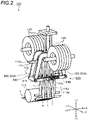
- FIG. 2 is a perspective view of the tape arranging device 140.
- FIG. 3 is a side view of the tape arranging device 140.
- FIG. 4 is a top view of the tape arranging device 140.
- guide roller units 210 are shown as guide roller units 210A to 210C.
- the tape arranging device 140 includes a plurality of guide roller units 210 and a moving unit 220.
- the tape arranging device 140 includes the number of guide roller units 210 corresponding to the number of the tape materials T. In the embodiments, the tape arranging device 140 includes seven guide roller units 210. As shown in FIG. 4 , the guide roller unit 210 includes a pair of roller bodies 212 and connecting portions 214. The roller bodies 212 each have a cylindrical shape or a columnar shape. The pair of roller bodies 212 are rotatably supported by the connecting portions 214. The pair of roller bodies 212 are supported by the connecting portions 214 such that rotation axes thereof are substantially parallel to each other. The connection portion 214 is rotatably supported by a first support portion 230 or a second support portion 240 to be described later. The connection portion 214 is supported by the first support portion 230 or the second support portion 240 such that the rotation axis of the roller body 212 and a rotation axis of the connection portion 214 are substantially parallel to each other.
- the tape material T having passed through the upstream support rollers 116a and 116b passes between the pair of roller bodies 212 configuring the guide roller unit 210.
- one tape material T passes through one guide roller unit 210.
- the tape material T that has passed through the upstream support roller 116a passes through facing surfaces of the guide roller unit 210 on a -Y-axis side in FIG. 2
- the tape material T that has passed through the upstream support roller 116b passes through facing surfaces of the guide roller unit 210 on a +Y-axis side in FIG. 2 .
- the moving unit 220 moves the guide roller units 210 to change a distance between adjacent guide roller units 210.
- the moving unit 220 includes the first support portion 230, the second support portion 240, a shaft portion 250, and the link unit 260.
- the first support portion 230 includes two support rods 232 and a connecting rod 234.
- the two support rods 232 are spaced apart from each other by a predetermined interval.
- Three guide roller units 210A are supported between the two support rods 232.
- the guide roller units 210A may serve as "first guide roller units”.
- the support rods 232 support the three guide roller units 210A such that the rotation axes of the guide roller units 210A, i.e. the rotation axes of the roller bodies 212 and the rotation axes of the connecting portions 214, are substantially parallel to one another (in the Y-axis direction in FIG. 4 ).
- the connecting rod 234 connects end portions 232a of the support rods 232 to each other.
- each of the end portions 232a may serve as a "second end portion".
- the second support portion 240 includes two support rods 242 and a connecting rod 244.
- the two support rods 242 are spaced apart from each other by a predetermined interval.
- the support rods 242 are provided substantially parallel to the support rods 232.
- Three guide roller units 210B are supported between the two support rods 242.
- the guide roller units 210B may serve as "second guide roller units”.
- the support rods 242 support the three guide roller units 210B such that the rotation axes of the guide roller units 210B, i.e. the rotation axes of the roller bodies 212 and the rotation axes of the connecting portions 214, are substantially parallel to one another (in the Y-axis direction in FIG. 4 ).
- the connecting rod 244 connects end portions 242a (one end portions) of the support rods 242 to each other. In one embodiment, each of the end portions 242a may serve as a "fourth end portion".
- the shaft portion 250 rotatably supports end portions 232b of the support rods 232 of the first support portion 230 and end portions 242b of the support rods 242 of the second support portion 240.
- each of the end portions 232b may serve as a "first end portion” and each of the end portions 242b may serve as a "third end portion”.
- the shaft portion 250 is fixed to a mount (not shown).
- a guide roller unit 210C is supported by the shaft portion 250.
- the shaft portion 250 supports the guide roller unit 210C such that a rotation axis of the guide roller unit 210C, i.e. the rotation axes of the roller bodies 212 and the rotation axes of the connection portions 214, is substantially parallel to the rotation axes of the guide roller units 210A and 210B (in the Y-axis direction in FIG. 4 ).
- the guide roller units 210A, 210B, and 210C are supported by the first support portion 230, the second support portion 240, and the shaft portion 250 such that the rotation axes thereof are substantially parallel to one another.
- the rotation axes of the guide roller units 210 (Y-axis direction in FIGS. 2 and 3 ) and the rotation axes of the upstream support roller 116a and the upstream support roller 116b (X-axis direction in FIGS. 2 and 3 ) are orthogonal to each other. Therefore, the tape materials T sent out from the upstream support roller 116a and the upstream support roller 116b and reaching the guide roller units 210 are each twisted (rotated) by 90 degrees around the Z axis in FIGS. 2 and 3 .
- the rotation axes of the guide roller units 210 (Y-axis direction in FIGS. 2 and 3 ) and the rotation axes of the downstream support roller 114a and the downstream support roller 114b (X-axis direction in FIGS. 2 and 3 ) are orthogonal to each other. Therefore, the tape materials T sent out from the guide roller units 210 and reaching the downstream support roller 114a and the downstream support roller 114b are each twisted by 90 degrees around the Z axis in FIGS. 2 and 3 .
- the link unit 260 (drive unit) rotates the first support portion 230 and the second support portion 240 in a direction in which the connecting rod 234, i.e. the end portions 232a of the first support portion 230, and the connecting rod 244, i.e. the end portions 242a of the second support portion 240, are away from each other or approach each other.
- the link unit 260 includes link members 262a and 262b and an actuator (not shown).
- the link member 262a is connected to the connecting rod 234.
- the link member 262b is connected to the connecting rod 244.
- the actuator moves the link members 262a and 262b in +Z-axis and -Z-axis directions in FIGS. 2 and 3 .
- the link unit 260 increase the tape pitch by rotating the first support portion 230 and the second support portion 240 in a direction in which the connecting rod 234 and the connecting rod 244 are away from each other.
- the link unit 260 reduce the tape pitch by rotating the first support portion 230 and the second support portion 240 in a direction in which the connecting rod 234 and the connecting rod 244 approach each other.
- FIGS. 5A and 5B diagrams illustrating movement of the first support portion 230 and the second support portion 240 moved by the link unit 260.
- FIG. 5A is a diagram illustrating a first position.
- FIG. 5B is a diagram illustrating a second position.
- dashed arrows indicate the feeding direction (passing direction) of the tape material T.
- the tape material T is indicated by cross-hatching.
- the guide roller units 210 are shown as the guide roller units 210A to 210C.
- the first position is a position where the guide roller units 210A, the guide roller units 210B, and the guide roller unit 210C are arranged adjacently in the X-axis direction in FIGS. 5A .
- the distance between adjacent guide roller units 210 is designed such that a target maximum full width TP1 is obtained when the guide roller units 210 are disposed at the first position.
- the full width is a width of the tape materials T when the tape materials T having passed through the guide roller units 210 are arranged without a gap in the width direction of the tape materials T (X-axis direction in FIGS. 5A and 5B ).
- the tape arranging device 140 arranges the tape materials T without a gap on a projection surface (XZ plane in FIGS. 5A and 5B ), by the guide roller units 210. Therefore, the tape materials T having passed through the guide roller units 210 are separated from each other in the Y-axis direction in FIGS. 5A and 5B (non-contact, see FIG. 2 ).
- a full width TP2 shown in FIG. 5B is smaller than the full width TP1 (see FIG. 5A ) of the tape materials T that have passed through the guide roller unit 210 at the first position.
- FIGS. 6A and 6B are diagrams illustrating the distance between the guide roller units 210 due to rotation.
- FIG. 6A is a diagram illustrating the distance between the guide roller units 210 at the first position.
- FIG. 6B is a diagram illustrating the distance between the guide roller units 210 after rotation.
- the guide roller units 210A are omitted in FIGS. 6A and 6B .
- the guide roller units 210B are disposed on the second support portion 240 so as to be spaced apart from each other by the same distance r on a straight line with the shaft portion 250 as a center.
- the guide roller units 210A are disposed on the first support portion 230 so as to be spaced apart from each other by the same distance r on the straight line with the shaft portion 250 as a center.
- the distance between adjacent guide roller units 210A and the distance between adjacent guide roller units 210B are always rcos ⁇ at equal distances. That is, when the first support portion 230 and the second support portion 240 are rotated by the rotation angle ⁇ and deformed into a V shape, the tape pitch (the distance between tape centers of the adjacent tapes) is always rcos ⁇ at equal distances. By changing the rotation angle ⁇ in this way, the tape pitch can be changed.
- the tape pitch is a minimum tape pitch when the link unit 260 moves the tape materials T to pass through the guide roller units 210 disposed at the second position.
- the width adjustment device 130 adjusts the width of each tape material T according to a desired tape pitch.
- the tape arranging device 140 can easily change the tape pitch while maintaining the number of the tape materials T with a simple structure in which the first support portion 230 and the second support portion 240 are simply rotated. Therefore, the composite material manufacturing apparatus 100 including the tape arranging device 140 can easily mold a structure.
- the composite material manufacturing apparatus 100 including the tape arranging device 140 can also perform steering lamination in which the fibers are laminated while changing directions of the fibers.
- the guide roller unit 210 presses a surface of the tape material in order to change the tape pitch.
- the tape arranging device 140 can change the tape pitch while preventing damage to the tape material T, as compared with a case where the tape arranging device 140 presses the end portion of the tape material T.
- the tape arranging device 140 include the guide roller units 210, the first support portion 230, the second support portion 240, the shaft portion 250, and the link unit 260. Accordingly, the tape arranging device 140 can relatively reduce the moving distance of the tape material T located at a position close to the central tape material T and relatively increase the moving distance of the tape material T located at a position far from the central tape material T with a simple structure in which the first support portion 230 and the second support portion 240 are simply rotated. Therefore, the tape arranging device 140 facilitates control related to the change of the tape pitch. Further, the tape arranging device 140 is lower in cost than that of the comparative example.
- the upstream support roller 116a and the upstream support roller 116b have different positions in the Y-axis direction in FIG. 2 . Therefore, when the tape materials T enter the guide roller units 210, a situation in which the adjacent tape materials T come into contact with each other can be avoided.
- the tape material T has adhesiveness, and when the tape materials T are integrated by contact with each other, there is a concern that the tape materials T may not be bent at the time of lamination. Therefore, the positions of the downstream support roller 114a and the downstream support roller 114b in the Y-axis direction and the Z-axis direction in FIG. 2 are made different from each other. Accordingly, the situation in which the adjacent tape materials T sent out from the guide roller units 210 come into contact with each other and are not bent at the time of lamination can be avoided.
- the guide roller unit 210 may include one roller body 212.
- the guide roller unit 210 with which the tape material T is to be brought into contact is different between a case of increasing the tape pitch and a case of reducing the tape pitch.
- the other roller body 212 is unnecessary because the tape material T is always in contact with the roller body 212 on one side thereof.
- the tape arranging device 140 includes one shaft portion 250 .
- a plurality of shaft portions 250 may be provided. That is, the support portions may be moved into a W shape (or M shape) by the moving unit 220.
- the guide roller unit 210C is supported by the shaft portion 250 as an example.
- the guide roller unit 210C is not an essential component.
- the guide roller unit 210C may be omitted.
- the number of guide roller units 210A may be different from the number of guide roller units 210B.
- downstream support roller 114a and the downstream support roller 114b are provided to be different in positions in the Y-axis direction in FIG. 1 is described as an example.
- the positions of the downstream support roller 114a and the downstream support roller 114b may be the same.
- the downstream support roller 114a and the downstream support roller 114b may be replaced by a single roller.
- the upstream support roller 116a and the upstream support roller 116b are provided to be different in positions in the Y-axis direction in FIG. 1 is described as an example.
- the positions of the upstream support roller 116a and the upstream support roller 116b may be the same.
- the upstream support roller 116a and the upstream support roller 116b may be replaced by a single roller.
- the downstream support rollers 114a and 114b, and the upstream support rollers 116a and 116b are not essential components.
- the downstream support rollers 114a and 114b can be omitted by disposing the compaction roller 112 at a position substantially corresponding to the downstream support rollers 114a and 114b in place of the downstream support rollers 114a and 114b.
- the upstream support rollers 116a and 116b can also be omitted by changing a receiving direction of the tape material T and changing the path of the tape material T.
- the width adjustment device 130 is not an essential component.
- the width adjustment device 130 is not provided, only the tape pitch is adjusted without changing the tape width.
- a plurality of tape materials can be arranged at any tape pitch.
- parallel includes not only perfect parallelism, but also substantial parallelism within a certain error range.
Landscapes
- Engineering & Computer Science (AREA)
- Robotics (AREA)
- Chemical & Material Sciences (AREA)
- Composite Materials (AREA)
- Mechanical Engineering (AREA)
- Moulding By Coating Moulds (AREA)
Abstract
Description
- The present disclosure relates to a tape arranging device for arranging tape materials.
- A composite material in which a resin (plastic) is combined with a fiber (fiber reinforced plastics (FRP)) is a material excellent in specific strength and specific rigidity. Therefore, the composite material is used as structural materials and the like in the fields of automobiles, aircrafts, and space. The composite material is produced by laminating prepregs, fibers impregnated with a resin, to form a laminate, and then hardening the resin as disclosed, for example, in Japanese Unexamined Patent Application Publication (
JP-A) No. 2011-093276 - In recent years, an automated fiber placement (AFP) method has attracted attention as a molding processing method capable of manufacturing a product having a complicated shape such as a three-dimensional curved surface with high accuracy and at high speed. The AFP method is a method in which a plurality of tape-shaped prepregs (hereinafter, simply referred to as "tape materials") are laminated adjacently without a gap in a width direction.
- The present disclosure relates to a tape arranging device. The tape arranging device includes guide roller units and a moving unit. Tape materials are capable of passing through the respective guide roller units. Each of the tape materials are configured with fibers impregnated with resin. The moving unit is configured to move the guide roller units and to change a distance between adjacent ones of the guide roller units. The adjacent ones of the guide roller units are adjacent to each other.
- The accompanying drawings are included to provide a further understanding of the disclosure and are incorporated in and constitute a part of this specification. The drawings illustrate an embodiment and, together with the specification, serve to explain the principles of the disclosure.
-
FIG. 1 is a diagram illustrating a composite material manufacturing apparatus according to an embodiment. -
FIG. 2 is a perspective view of a tape arranging device. -
FIG. 3 is a side view of the tape arranging device. -
FIG. 4 is a top view of the tape arranging device. -
FIGS. 5A and 5B are diagrams illustrating movement of a first support portion and a second support portion that are moved by a link unit. -
FIGS. 6A and 6B are diagrams illustrating a distance between guide roller units due to rotation of the first support portion and the second support portion. - When a product having a complicated shape such as a three-dimensional curved surface is formed by using a tape material, it is desired to laminate tape materials arranged adjacently while appropriately changing a width of the tape materials. Hereinafter, a distance between center lines of adjacent tape materials is referred to as a "tape pitch" in a sheet configured with the tape materials arranged without a gap. When the tape pitch is changed, a width of the tape material itself may also be changed. Therefore, it is desired to develop a technique of arranging tape materials without a gap even when the width of the tape material is changed.
- The present disclosure relates to a tape arranging device capable of arranging tape materials at any tape pitch.
- In the following, some embodiments of the disclosure are described in detail with reference to the accompanying drawings. Note that the following description is directed to illustrative examples of the disclosure and not to be construed as limiting to the disclosure. Factors including, without limitation, numerical values, shapes, materials, components, positions of the components, and how the components are coupled to each other are illustrative only and not to be construed as limiting to the disclosure. Further, elements in the following example embodiments which are not recited in a most-generic independent claim of the disclosure are optional and may be provided on an as-needed basis. The drawings are schematic and are not intended to be drawn to scale. Throughout the present specification and the drawings, elements having substantially the same function and configuration are denoted with the same numerals to avoid any redundant description.
-
FIG. 1 is a diagram illustrating a compositematerial manufacturing apparatus 100 according to the embodiments. As shown inFIG. 1 , the compositematerial manufacturing apparatus 100 includes a feeding device 110,heating devices 120,width adjusting devices 130, atape arranging device 140, and acentral control unit 150. In the following drawings includingFIG. 1 in the embodiments, an X axis, a Y axis, and a Z axis which perpendicular to each other are defined as shown with respect to thetape arranging device 140. Further, inFIG. 1 , a broken line arrow indicates a feeding direction of a tape material T by the feeding device 110. - The feeding device 110 sends out the tape material T supplied from a stock roller or the like around which the tape material T is wound. In the embodiments, the feeding device 110 sends out seven tape materials T, but the number of tape materials T is not limited to seven.
- The tape material T is configured with prepregs. Prepregs are fibers impregnated with resin. The prepreg is used as a material of FRP (a composite material) such as CFRP or GFRP.
- The fibers configuring the tape material T are, for example, any one or more of carbon fibers, glass fibers, boron fibers, aramid fibers, and polyarylate fibers. Polyarylate fibers includes, for example, Vectran, which is a registered trademark.
- The resin configuring the tape material T is a thermosetting resin or a thermoplastic resin.
- The thermosetting resin is, for example, any one or more of phenol resin (PF), epoxy resin (EP), melamine resin (MF), urea resin (UF), unsaturated polyester resin (UP), alkyd resin, polyurethane (PUR), thermosetting polyimide (PI), benzoxazine, and polybismaleimide (BMI).
- The thermoplastic resin is, for example, any one or more of polyphenylene sulfide (PPS), pre-tetrafluoroethylene, polysulfone (PSF), polyether sulfone (PES), amorphous polyarylate (PAR), liquid crystal polymer (LCP), polyether ether ketone (PEEK), thermoplastic polyimide (PI), polyamide imide (PAI), polyamide (PA), nylon, polyacetal (POM), polycarbonate (PC), modified polyphenylene ether (modified PPE), polyethylene terephthalate (PET), polybutylene terephthalate (PBT), cyclic polyolefin (COP), polyethylene (PE), polypropylene (PP), polyvinyl chloride (PVC), polyvinylidene chloride, polystyrene (PS), polyvinyl acetate (PVAc), polyurethane (PUR), ABS resin, AS resin, acrylic resin (PMMA), and polyetherketone ketone (PEKK).
- As shown in
FIG. 1 , the feeding device 110 includes acompaction roller 112,downstream support rollers upstream support rollers 116a and 116b. - The
compaction roller 112, thedownstream support rollers upstream support rollers 116a and 116b each have a cylindrical shape. Thecompaction roller 112, thedownstream support rollers upstream support rollers 116a and 116b are arranged such that rotation axes thereof are in an X-axis direction inFIG. 1 . - The
compaction roller 112, thedownstream support rollers upstream support rollers 116a and 116b are provided at different positions in a flow direction of the tape material T. In the embodiments, thecompaction roller 112 is provided downstream of thedownstream support rollers downstream support rollers upstream support rollers 116a and 116b in the feeding direction of the tape material T. That is, theupstream support rollers 116a and 116b, thedownstream support rollers compaction roller 112 are provided in this order from an upstream side in the feeding direction of the tape material T. - In the embodiments, the
downstream support roller 114a and thedownstream support roller 114b are provided to be different in positions in a Y-axis direction and a Z-axis direction inFIG. 1 . Further, theupstream support roller 116a and the upstream support roller 116b are provided to be different in positions in the Y-axis direction inFIG. 1 . - The
compaction roller 112 is moved while being pressed against a mold, and thereby thecompaction roller 112 is passively rotated due to an adhesive force or a frictional force of the tape material T. - The tape materials T are stretched between the
downstream support rollers upstream support rollers 116a and 116b. Four tape materials T are stretched between thedownstream support roller 114a and theupstream support roller 116a. Three tape materials T are stretched between thedownstream support roller 114b and the upstream support roller 116b. - The
downstream support rollers upstream support rollers 116a and 116b change directions of the tape materials T such that each of the tape materials T vertically passes through an inside of thetape arranging device 140. Thedownstream support rollers upstream support rollers 116a and 116b are rotated due to a frictional force or an adhesive force when the tape material T is sent out for lamination. - The
heating devices 120 heats the tape materials T. Theheating devices 120 are implemented by, for example, an electric heater, a heat exchanger, or a warm air blower. Theheating devices 120 are provided upstream of thewidth adjusting device 130 in the feeding direction of the tape material T. - The
width adjusting devices 130 are provided between theheating device 120 and theupstream support rollers 116a and 116b. Thewidth adjusting devices 130 are fixed to a mount (not shown). Thewidth adjusting device 130 changes, in response to a control command from thecentral control unit 150 to be described later, the width of the tape material T that has passed through theheating device 120. In the embodiments, the number ofwidth adjustment devices 130 corresponding to the number of the tape materials T are provided, and each of thewidth adjusting device 130 changes a width of one tape material T. In this case, seven adjustment devices are provided. In the embodiments, each of thewidth adjusting devices 130 changes the width of the tape material T to substantially the same width. Thewidth adjusting device 130 includes a main body which is formed by a bottom surface and a pair of wall surfaces whose interval gradually decreases and which has a path through which the tape material T passes. Thewidth adjusting device 130 may include various techniques such as a technique of changing the interval between the wall surfaces at an outlet of the tape material in the path by changing a rotation angle of the main body, and a detailed description of the various techniques will be omitted here. - The
width adjusting devices 130 adjust the widths of the respective tape materials T based on a tape width (tape pitch) of a sheet configured with the tape materials T that are sent out from thecompaction roller 112 and arranged without a gap. - The tape materials T whose widths have been changed by the
width adjusting devices 130 pass through theupstream support roller 116a and the upstream support roller 116b, and then the tape materials T are arranged without gaps by thetape arranging device 140. After that, the tape materials T pass through thedownstream support rollers compaction roller 112, then are laminated on a mold, are maintained at a predetermined temperature, and are formed into a composite material. Thetape arranging device 140 will be described in detail later. - The
central control unit 150 is configured with a semiconductor integrated circuit including a central processing unit (CPU). Thecentral control unit 150 reads, from the ROM, programs, parameters, and the like for operating the CPU. Thecentral control unit 150 manages and controls the entire compositematerial manufacturing apparatus 100 in cooperation with a RAM serving as a work area and other electronic circuits. In the embodiments, thecentral control unit 150 controls thewidth adjusting devices 130 and a link unit 260 (drive unit) of thetape arranging device 140 to be described later. - The
tape arranging device 140 arranges the tape materials T, the widths of which have been changed by thewidth adjusting devices 130, without gaps. -
FIG. 2 is a perspective view of thetape arranging device 140.FIG. 3 is a side view of thetape arranging device 140.FIG. 4 is a top view of thetape arranging device 140. InFIG. 4 , guideroller units 210 are shown asguide roller units 210A to 210C. - As shown in
FIGS. 2 to 4 , thetape arranging device 140 includes a plurality ofguide roller units 210 and a movingunit 220. - The
tape arranging device 140 includes the number ofguide roller units 210 corresponding to the number of the tape materials T. In the embodiments, thetape arranging device 140 includes sevenguide roller units 210. As shown inFIG. 4 , theguide roller unit 210 includes a pair ofroller bodies 212 and connectingportions 214. Theroller bodies 212 each have a cylindrical shape or a columnar shape. The pair ofroller bodies 212 are rotatably supported by the connectingportions 214. The pair ofroller bodies 212 are supported by the connectingportions 214 such that rotation axes thereof are substantially parallel to each other. Theconnection portion 214 is rotatably supported by afirst support portion 230 or asecond support portion 240 to be described later. Theconnection portion 214 is supported by thefirst support portion 230 or thesecond support portion 240 such that the rotation axis of theroller body 212 and a rotation axis of theconnection portion 214 are substantially parallel to each other. - The tape material T having passed through the
upstream support rollers 116a and 116b passes between the pair ofroller bodies 212 configuring theguide roller unit 210. In the embodiments, one tape material T passes through oneguide roller unit 210. As shown inFIG. 2 , in the embodiments, the tape material T that has passed through theupstream support roller 116a passes through facing surfaces of theguide roller unit 210 on a -Y-axis side inFIG. 2 , and the tape material T that has passed through the upstream support roller 116b passes through facing surfaces of theguide roller unit 210 on a +Y-axis side inFIG. 2 . - The moving
unit 220 moves theguide roller units 210 to change a distance between adjacentguide roller units 210. In the embodiments, the movingunit 220 includes thefirst support portion 230, thesecond support portion 240, ashaft portion 250, and thelink unit 260. - As shown in
FIG. 4 , thefirst support portion 230 includes twosupport rods 232 and a connectingrod 234. The twosupport rods 232 are spaced apart from each other by a predetermined interval. Threeguide roller units 210A are supported between the twosupport rods 232. In one embodiment theguide roller units 210A may serve as "first guide roller units". Thesupport rods 232 support the threeguide roller units 210A such that the rotation axes of theguide roller units 210A, i.e. the rotation axes of theroller bodies 212 and the rotation axes of the connectingportions 214, are substantially parallel to one another (in the Y-axis direction inFIG. 4 ). The connectingrod 234 connectsend portions 232a of thesupport rods 232 to each other. In one embodiment, each of theend portions 232a may serve as a "second end portion". - The
second support portion 240 includes twosupport rods 242 and a connectingrod 244. The twosupport rods 242 are spaced apart from each other by a predetermined interval. Thesupport rods 242 are provided substantially parallel to thesupport rods 232. Threeguide roller units 210B are supported between the twosupport rods 242. In one embodiment theguide roller units 210B may serve as "second guide roller units". Thesupport rods 242 support the threeguide roller units 210B such that the rotation axes of theguide roller units 210B, i.e. the rotation axes of theroller bodies 212 and the rotation axes of the connectingportions 214, are substantially parallel to one another (in the Y-axis direction inFIG. 4 ). The connectingrod 244 connectsend portions 242a (one end portions) of thesupport rods 242 to each other. In one embodiment, each of theend portions 242a may serve as a "fourth end portion". - The
shaft portion 250 rotatably supportsend portions 232b of thesupport rods 232 of thefirst support portion 230 and endportions 242b of thesupport rods 242 of thesecond support portion 240. In one embodiment, each of theend portions 232b may serve as a "first end portion" and each of theend portions 242b may serve as a "third end portion". Theshaft portion 250 is fixed to a mount (not shown). Aguide roller unit 210C is supported by theshaft portion 250. Theshaft portion 250 supports theguide roller unit 210C such that a rotation axis of theguide roller unit 210C, i.e. the rotation axes of theroller bodies 212 and the rotation axes of theconnection portions 214, is substantially parallel to the rotation axes of theguide roller units FIG. 4 ). - That is, the
guide roller units first support portion 230, thesecond support portion 240, and theshaft portion 250 such that the rotation axes thereof are substantially parallel to one another. - Description will be made referring back to
FIGS. 2 and3 , the rotation axes of the guide roller units 210 (Y-axis direction inFIGS. 2 and3 ) and the rotation axes of theupstream support roller 116a and the upstream support roller 116b (X-axis direction inFIGS. 2 and3 ) are orthogonal to each other. Therefore, the tape materials T sent out from theupstream support roller 116a and the upstream support roller 116b and reaching theguide roller units 210 are each twisted (rotated) by 90 degrees around the Z axis inFIGS. 2 and3 . - Similarly, the rotation axes of the guide roller units 210 (Y-axis direction in
FIGS. 2 and3 ) and the rotation axes of thedownstream support roller 114a and thedownstream support roller 114b (X-axis direction inFIGS. 2 and3 ) are orthogonal to each other. Therefore, the tape materials T sent out from theguide roller units 210 and reaching thedownstream support roller 114a and thedownstream support roller 114b are each twisted by 90 degrees around the Z axis inFIGS. 2 and3 . - The link unit 260 (drive unit) rotates the
first support portion 230 and thesecond support portion 240 in a direction in which the connectingrod 234, i.e. theend portions 232a of thefirst support portion 230, and the connectingrod 244, i.e. theend portions 242a of thesecond support portion 240, are away from each other or approach each other. In the embodiments, thelink unit 260 includeslink members link member 262a is connected to the connectingrod 234. Thelink member 262b is connected to the connectingrod 244. The actuator moves thelink members FIGS. 2 and3 . - The
link unit 260 increase the tape pitch by rotating thefirst support portion 230 and thesecond support portion 240 in a direction in which the connectingrod 234 and the connectingrod 244 are away from each other. On the other hand, thelink unit 260 reduce the tape pitch by rotating thefirst support portion 230 and thesecond support portion 240 in a direction in which the connectingrod 234 and the connectingrod 244 approach each other. -
FIGS. 5A and 5B diagrams illustrating movement of thefirst support portion 230 and thesecond support portion 240 moved by thelink unit 260.FIG. 5A is a diagram illustrating a first position.FIG. 5B is a diagram illustrating a second position. InFIGS. 5A and 5B , dashed arrows indicate the feeding direction (passing direction) of the tape material T. InFIGS. 5A and 5B , the tape material T is indicated by cross-hatching. Further, inFIGS. 5A and 5B , theguide roller units 210 are shown as theguide roller units 210A to 210C. - As shown in
FIG. 5A , the first position is a position where theguide roller units 210A, theguide roller units 210B, and theguide roller unit 210C are arranged adjacently in the X-axis direction inFIGS. 5A . In the embodiments, the distance between adjacentguide roller units 210 is designed such that a target maximum full width TP1 is obtained when theguide roller units 210 are disposed at the first position. The full width is a width of the tape materials T when the tape materials T having passed through theguide roller units 210 are arranged without a gap in the width direction of the tape materials T (X-axis direction inFIGS. 5A and 5B ). - In the embodiments, the
tape arranging device 140 arranges the tape materials T without a gap on a projection surface (XZ plane inFIGS. 5A and 5B ), by theguide roller units 210. Therefore, the tape materials T having passed through theguide roller units 210 are separated from each other in the Y-axis direction inFIGS. 5A and 5B (non-contact, seeFIG. 2 ). - At the first position, when the connecting
rod 234 of thefirst support portion 230 and the connectingrod 244 of thesecond support portion 240 are moved toward the -Z-axis direction inFIG. 5A (shown by white arrows inFIG. 5A ) by thelink unit 260, thefirst support portion 230 and thesecond support portion 240 rotate around theshaft portion 250 with theshaft portion 250 as a rotation axis. Then, as shown inFIG. 5B , the connectingrod 234 of thefirst support portion 230 and the connectingrod 244 of thesecond support portion 240 approach each other, and thefirst support portion 230 and thesecond support portion 240 form a V shape with theshaft portion 250 as a base point. Therefore, a full width TP2 shown inFIG. 5B is smaller than the full width TP1 (seeFIG. 5A ) of the tape materials T that have passed through theguide roller unit 210 at the first position. -
FIGS. 6A and 6B are diagrams illustrating the distance between theguide roller units 210 due to rotation.FIG. 6A is a diagram illustrating the distance between theguide roller units 210 at the first position.FIG. 6B is a diagram illustrating the distance between theguide roller units 210 after rotation. In order to facilitate understanding, theguide roller units 210A are omitted inFIGS. 6A and 6B . - As shown in
FIG. 6A , at the first position, theguide roller units 210B are disposed on thesecond support portion 240 so as to be spaced apart from each other by the same distance r on a straight line with theshaft portion 250 as a center. Similarly, at the first position, theguide roller units 210A are disposed on thefirst support portion 230 so as to be spaced apart from each other by the same distance r on the straight line with theshaft portion 250 as a center. - As shown in
FIG. 6B , when thefirst support portion 230 and thesecond support portion 240 are rotated by a rotation angle θ and deformed into a V shape, the distance between adjacentguide roller units 210A and the distance between adjacentguide roller units 210B are always rcosθ at equal distances. That is, when thefirst support portion 230 and thesecond support portion 240 are rotated by the rotation angle θ and deformed into a V shape, the tape pitch (the distance between tape centers of the adjacent tapes) is always rcosθ at equal distances. By changing the rotation angle θ in this way, the tape pitch can be changed. - Further, in the embodiments, the tape pitch is a minimum tape pitch when the
link unit 260 moves the tape materials T to pass through theguide roller units 210 disposed at the second position. - As described above, the
width adjustment device 130 adjusts the width of each tape material T according to a desired tape pitch. - As described above, the
tape arranging device 140 according to the embodiments can easily change the tape pitch while maintaining the number of the tape materials T with a simple structure in which thefirst support portion 230 and thesecond support portion 240 are simply rotated. Therefore, the compositematerial manufacturing apparatus 100 including thetape arranging device 140 can easily mold a structure. The compositematerial manufacturing apparatus 100 including thetape arranging device 140 can also perform steering lamination in which the fibers are laminated while changing directions of the fibers. - When the tape pitch is changed by pressing the end portion of the tape material T, the end portion of the tape material T is deformed and the tape width is changed. Accordingly, in the
tape arrangement device 140 of the embodiments, theguide roller unit 210 presses a surface of the tape material in order to change the tape pitch. As a result, thetape arranging device 140 can change the tape pitch while preventing damage to the tape material T, as compared with a case where thetape arranging device 140 presses the end portion of the tape material T. - Further, when the tape pitch is changed without changing a position of the central tape material T, it is necessary to relatively reduce a moving distance of the tape material T at a position close to the central tape material T and relatively increase a moving distance of the tape material T at a position far from the central tape material T.
- For this reason, in a comparative example in which a moving device is provided for each tape material T, the moving device is complicated, and control is difficult, so that there is a problem that many moving devices cannot be mounted on a laminating apparatus due to interference of the moving devices.
- In contrast, as described above, the
tape arranging device 140 according to the embodiments include theguide roller units 210, thefirst support portion 230, thesecond support portion 240, theshaft portion 250, and thelink unit 260. Accordingly, thetape arranging device 140 can relatively reduce the moving distance of the tape material T located at a position close to the central tape material T and relatively increase the moving distance of the tape material T located at a position far from the central tape material T with a simple structure in which thefirst support portion 230 and thesecond support portion 240 are simply rotated. Therefore, thetape arranging device 140 facilitates control related to the change of the tape pitch. Further, thetape arranging device 140 is lower in cost than that of the comparative example. - As described above, the
upstream support roller 116a and the upstream support roller 116b have different positions in the Y-axis direction inFIG. 2 . Therefore, when the tape materials T enter theguide roller units 210, a situation in which the adjacent tape materials T come into contact with each other can be avoided. - Further, the tape material T has adhesiveness, and when the tape materials T are integrated by contact with each other, there is a concern that the tape materials T may not be bent at the time of lamination. Therefore, the positions of the
downstream support roller 114a and thedownstream support roller 114b in the Y-axis direction and the Z-axis direction inFIG. 2 are made different from each other. Accordingly, the situation in which the adjacent tape materials T sent out from theguide roller units 210 come into contact with each other and are not bent at the time of lamination can be avoided. - Although the preferred embodiment has been described above with reference to the accompanying drawings, it is needless to say that the present invention is not limited to the embodiment. It is apparent that those skilled in the art can conceive of various modifications and alterations within the scope described in the claims, and it is understood that such modifications and alterations naturally fall within the technical scope of the present invention.
- For example, in the above embodiment, a configuration in which the
guide roller unit 210 includes a pair ofroller bodies 212 is described as an example. However, theguide roller unit 210 may include oneroller body 212. In the above embodiment, since the tape material T is introduced into theguide roller unit 210 from the -Z-axis direction, theguide roller unit 210 with which the tape material T is to be brought into contact is different between a case of increasing the tape pitch and a case of reducing the tape pitch. However, when the tape material T is introduced to theguide roller unit 210 from the X-axis direction, and the feeding direction of the tape material T is changed in theguide roller unit 210, theother roller body 212 is unnecessary because the tape material T is always in contact with theroller body 212 on one side thereof. - In the above embodiment, a configuration in which the
tape arranging device 140 includes oneshaft portion 250 is described as an example. However, a plurality ofshaft portions 250 may be provided. That is, the support portions may be moved into a W shape (or M shape) by the movingunit 220. - In the above embodiment, a case in which the
guide roller unit 210C is supported by theshaft portion 250 is described as an example. However, theguide roller unit 210C is not an essential component. For example, when the number of the tape materials T is an even number, theguide roller unit 210C may be omitted. Further, the number ofguide roller units 210A may be different from the number ofguide roller units 210B. - In the above embodiment, a case in which the
downstream support roller 114a and thedownstream support roller 114b are provided to be different in positions in the Y-axis direction inFIG. 1 is described as an example. However, the positions of thedownstream support roller 114a and thedownstream support roller 114b may be the same. Thedownstream support roller 114a and thedownstream support roller 114b may be replaced by a single roller. Similarly, in the above embodiment, theupstream support roller 116a and the upstream support roller 116b are provided to be different in positions in the Y-axis direction inFIG. 1 is described as an example. However, the positions of theupstream support roller 116a and the upstream support roller 116b may be the same. Further, theupstream support roller 116a and the upstream support roller 116b may be replaced by a single roller. - In the above embodiment, a configuration in which the composite
material manufacturing apparatus 100 includes thedownstream support rollers upstream support rollers 116a and 116b is described as an example. However, thedownstream support rollers upstream support rollers 116a and 116b are not essential components. For example, thedownstream support rollers compaction roller 112 at a position substantially corresponding to thedownstream support rollers downstream support rollers upstream support rollers 116a and 116b can also be omitted by changing a receiving direction of the tape material T and changing the path of the tape material T. - In the above embodiment, a configuration in which the composite
material manufacturing apparatus 100 includes thewidth adjusting devices 130 is described as an example. However, thewidth adjustment device 130 is not an essential component. When thewidth adjustment device 130 is not provided, only the tape pitch is adjusted without changing the tape width. - According to the present disclosure, a plurality of tape materials can be arranged at any tape pitch.
- In the present disclosure, "parallel" includes not only perfect parallelism, but also substantial parallelism within a certain error range.
Claims (8)
- A tape arranging device comprising:guide roller units through which tape materials are capable of passing respectively, each of the tape materials being configured with fibers impregnated with resin; anda moving unit configured to move the guide roller units and to change a distance between adjacent ones of the guide roller units, the adjacent ones of the guide roller units being adjacent to each other.
- The tape arranging device according to claim 1,
wherein the moving unit is configured to move the guide roller units so as to change positions of the adjacent ones of the guide roller units in a direction in which the tape materials are to pass through the guide roller units. - The tape arranging device according to claim 1 or 2,wherein the moving unit includes a first support portion, a second support portion, a shaft portion, and a drive unit, the first support portion including a first end portion and a second end portion opposite to the first end portion, the second support portion including a third end portion and a fourth end portion opposite to the third end portion,wherein the adjacent ones of the guide roller units include first guide roller units and second guide roller units, the first guide roller units being adjacent to each other, the second guide roller units being adjacent to each other,wherein the first support portion supports the first guide roller units such that rotation axes of the first guide roller units are parallel to each other,wherein the second support portion supports the second guide roller units such that rotation axes of the second guide roller units are parallel to each other,wherein the shaft portion rotatably supports the first end portion of the first support portion and the third end portion of the second support portion, andwherein the drive unit is configured to rotate the first support portion and the second support portion in a direction in which the second end portion of the first support portion and the fourth end portion of the second support portion are away from each other or in a direction in which the second end portion of the first support portion and the fourth end portion of the second support portion approach each other.
- The tape arranging device according to claim 1 or 2,wherein the moving unit includes a first support portion, a second support portion, a shaft portion, and a drive unit, the first support portion including a first end portion and a second end portion opposite to the first end portion, the second support portion including a third end portion and a fourth end portion opposite to the third end portion,wherein the guide roller units include a first guide roller unit and a second guide roller unit,wherein the first support portion supports the first guide roller unit,wherein the second support portion supports the second guide roller unit,wherein the shaft portion rotatably supports the first end portion of the first support portion and the third end portion of the second support portion, andwherein the drive unit is configured to rotate the first support portion and the second support portion in a direction in which the second end portion of the first support portion and the fourth end portion of the second support portion are away from each other or in a direction in which the second end portion of the first support portion and the fourth end portion of the second support portion approach each other.
- The tape arranging device according to claim 3,wherein each of the guide roller units includes:a pair of roller bodies, andconnecting portions configured to rotatably support the pair of roller bodies such that rotation axes of the pair of roller bodies are parallel to each other, andwherein the connecting portions are rotatably supported by the first support portion or the second support portion.
- The tape arranging device according to claim 4,wherein each of the guide roller units includes:a pair of roller bodies, andconnecting portions configured to rotatably support the pair of roller bodies such that rotation axes of the pair of roller bodies are parallel to each other, andwherein the connecting portions are rotatably supported by the first support portion or the second support portion.
- The tape arranging device according to claim 5,
wherein the adjacent ones of the guide roller units are configured such that the rotation axes of the roller bodies of the first guide roller units are parallel to the rotation axes of the roller bodies of the second guide roller units. - The tape arranging device according to claim 6,
wherein the adjacent ones of the guide roller units are configured such that the rotation axes of the roller bodies of the first guide roller unit are parallel to the rotation axes of the roller bodies of the second guide roller unit.
Applications Claiming Priority (1)
| Application Number | Priority Date | Filing Date | Title |
|---|---|---|---|
| JP2021029124A JP7595484B2 (en) | 2021-02-25 | 2021-02-25 | Tape arrangement mechanism |
Publications (3)
| Publication Number | Publication Date |
|---|---|
| EP4049836A1 true EP4049836A1 (en) | 2022-08-31 |
| EP4049836C0 EP4049836C0 (en) | 2025-02-26 |
| EP4049836B1 EP4049836B1 (en) | 2025-02-26 |
Family
ID=80447181
Family Applications (1)
| Application Number | Title | Priority Date | Filing Date |
|---|---|---|---|
| EP22157873.5A Active EP4049836B1 (en) | 2021-02-25 | 2022-02-22 | Tape arranging device |
Country Status (3)
| Country | Link |
|---|---|
| US (1) | US11919257B2 (en) |
| EP (1) | EP4049836B1 (en) |
| JP (1) | JP7595484B2 (en) |
Cited By (1)
| Publication number | Priority date | Publication date | Assignee | Title |
|---|---|---|---|---|
| EP4578638A1 (en) * | 2023-12-25 | 2025-07-02 | Subaru Corporation | Fiber width adjustment device and method of molding composite material |
Families Citing this family (5)
| Publication number | Priority date | Publication date | Assignee | Title |
|---|---|---|---|---|
| JP2024047485A (en) | 2022-09-26 | 2024-04-05 | 株式会社Subaru | Roller unit for tape delivery, fiber laminating device, and composite material molding method |
| JP2024047483A (en) | 2022-09-26 | 2024-04-05 | 株式会社Subaru | Roller unit for tape delivery, fiber laminating device, and composite material molding method |
| JP2024047484A (en) | 2022-09-26 | 2024-04-05 | 株式会社Subaru | Preform manufacturing method and composite material molding method |
| JP2024128611A (en) | 2023-03-10 | 2024-09-24 | 株式会社Subaru | Fiber laminating device and composite material molding method |
| CN116766631B (en) * | 2023-08-22 | 2023-11-03 | 太原理工大学 | A two-way tape laying robot adapted to multi-width prepreg tapes and a tape laying method |
Citations (3)
| Publication number | Priority date | Publication date | Assignee | Title |
|---|---|---|---|---|
| DE102008016989A1 (en) * | 2007-04-02 | 2008-10-09 | Cetex Institut für Textil- und Verarbeitungsmaschinen gemeinnützige GmbH | Method and device for partially reinforcing a web |
| JP2011093276A (en) | 2009-11-02 | 2011-05-12 | Toyota Motor Corp | Filament winding system, system of manufacturing pressure vessel, and method of manufacturing pressure vessel |
| JP2020059145A (en) * | 2018-10-05 | 2020-04-16 | 福井県 | Laminate device and laminate method of prepreg tape |
Family Cites Families (4)
| Publication number | Priority date | Publication date | Assignee | Title |
|---|---|---|---|---|
| US8986482B2 (en) | 2008-07-08 | 2015-03-24 | The Boeing Company | Method and apparatus for producing composite structures |
| JP6194909B2 (en) * | 2015-03-10 | 2017-09-13 | トヨタ自動車株式会社 | Filament winding equipment |
| JP2017209902A (en) | 2016-05-26 | 2017-11-30 | トヨタ自動車株式会社 | Filament winding device |
| CN112004660B (en) | 2018-10-05 | 2023-06-06 | 福井县 | Automatic lamination method and device for thin layer strips |
-
2021
- 2021-02-25 JP JP2021029124A patent/JP7595484B2/en active Active
-
2022
- 2022-02-11 US US17/669,870 patent/US11919257B2/en active Active
- 2022-02-22 EP EP22157873.5A patent/EP4049836B1/en active Active
Patent Citations (3)
| Publication number | Priority date | Publication date | Assignee | Title |
|---|---|---|---|---|
| DE102008016989A1 (en) * | 2007-04-02 | 2008-10-09 | Cetex Institut für Textil- und Verarbeitungsmaschinen gemeinnützige GmbH | Method and device for partially reinforcing a web |
| JP2011093276A (en) | 2009-11-02 | 2011-05-12 | Toyota Motor Corp | Filament winding system, system of manufacturing pressure vessel, and method of manufacturing pressure vessel |
| JP2020059145A (en) * | 2018-10-05 | 2020-04-16 | 福井県 | Laminate device and laminate method of prepreg tape |
Cited By (1)
| Publication number | Priority date | Publication date | Assignee | Title |
|---|---|---|---|---|
| EP4578638A1 (en) * | 2023-12-25 | 2025-07-02 | Subaru Corporation | Fiber width adjustment device and method of molding composite material |
Also Published As
| Publication number | Publication date |
|---|---|
| JP7595484B2 (en) | 2024-12-06 |
| US11919257B2 (en) | 2024-03-05 |
| EP4049836C0 (en) | 2025-02-26 |
| EP4049836B1 (en) | 2025-02-26 |
| JP2022130133A (en) | 2022-09-06 |
| US20220266545A1 (en) | 2022-08-25 |
Similar Documents
| Publication | Publication Date | Title |
|---|---|---|
| EP4049836B1 (en) | Tape arranging device | |
| US11597168B2 (en) | Thin-layer tape automated lamination method and device | |
| KR101755015B1 (en) | Transformer controlling movement of head unit and tension and temperature of plastic formable material | |
| CN111479673B (en) | Production line and method for producing products made of fiber-reinforced plastic | |
| EP3664985B1 (en) | System and process for manufacturing aligned discontinuous fiber composites | |
| JP4874335B2 (en) | Apparatus for producing a fiber structure preform having a desired surface shape by a TFP process | |
| WO2017150186A1 (en) | Three-dimensional printing apparatus and three-dimensional printing method | |
| KR20160128004A (en) | Three-dimensional product manufacturing robot for plastic formable materials | |
| JP4981801B2 (en) | Guide device for apparatus for manufacturing fiber preforms by TFP process for composite parts | |
| KR20170085368A (en) | Head unit and head supply unit for controlling discharge of raw material made of plastic formable materials | |
| CN102555230A (en) | Resin delivery, application and infusion system and integrated layup system and method of use | |
| US11141936B2 (en) | Fiber width adjusting apparatus, fiber width adjusting method, and composite forming method | |
| US12521945B2 (en) | Roller unit for feeding tapes, fiber placement apparatus and method of molding composite material | |
| US12194692B2 (en) | Fiber arranging device, method of arranging fibers and method of molding composite material | |
| CN113518697A (en) | Sheet pressing device, sheet pressing method, pressing roller, and sheet manufacturing method | |
| CN107709645B (en) | Fiber laminate, method for producing fiber laminate, and fiber-reinforced composite material | |
| EP3597414B1 (en) | Apparatuses and methods for fabricating a composite structure and reacting to a placement force | |
| JP4873879B2 (en) | Manufacturing method and manufacturing apparatus for multi-axis multilayer reinforcing sheet | |
| JP7495803B2 (en) | Composite Material Manufacturing Equipment | |
| KR20180132247A (en) | Apparatus for manufacturing preform using frp tape | |
| US20150130109A1 (en) | Method and device for producing a textile preform | |
| US11230072B2 (en) | Apparatuses for fabricating a composite structure and reacting to a placement force | |
| JP7547742B2 (en) | Manufacturing method of fiber-reinforced substrate, manufacturing method of fiber-reinforced substrate and shutter blade | |
| CN110723271B (en) | Apparatus and method for making composite structures and reacting to placement forces | |
| KR101944748B1 (en) | Three-dimensional product using polymer composite material and manufacturing robot system thereof |
Legal Events
| Date | Code | Title | Description |
|---|---|---|---|
| PUAI | Public reference made under article 153(3) epc to a published international application that has entered the european phase |
Free format text: ORIGINAL CODE: 0009012 |
|
| STAA | Information on the status of an ep patent application or granted ep patent |
Free format text: STATUS: THE APPLICATION HAS BEEN PUBLISHED |
|
| AK | Designated contracting states |
Kind code of ref document: A1 Designated state(s): AL AT BE BG CH CY CZ DE DK EE ES FI FR GB GR HR HU IE IS IT LI LT LU LV MC MK MT NL NO PL PT RO RS SE SI SK SM TR |
|
| STAA | Information on the status of an ep patent application or granted ep patent |
Free format text: STATUS: REQUEST FOR EXAMINATION WAS MADE |
|
| 17P | Request for examination filed |
Effective date: 20230227 |
|
| RBV | Designated contracting states (corrected) |
Designated state(s): AL AT BE BG CH CY CZ DE DK EE ES FI FR GB GR HR HU IE IS IT LI LT LU LV MC MK MT NL NO PL PT RO RS SE SI SK SM TR |
|
| STAA | Information on the status of an ep patent application or granted ep patent |
Free format text: STATUS: EXAMINATION IS IN PROGRESS |
|
| 17Q | First examination report despatched |
Effective date: 20231122 |
|
| GRAP | Despatch of communication of intention to grant a patent |
Free format text: ORIGINAL CODE: EPIDOSNIGR1 |
|
| STAA | Information on the status of an ep patent application or granted ep patent |
Free format text: STATUS: GRANT OF PATENT IS INTENDED |
|
| INTG | Intention to grant announced |
Effective date: 20240917 |
|
| GRAS | Grant fee paid |
Free format text: ORIGINAL CODE: EPIDOSNIGR3 |
|
| GRAA | (expected) grant |
Free format text: ORIGINAL CODE: 0009210 |
|
| STAA | Information on the status of an ep patent application or granted ep patent |
Free format text: STATUS: THE PATENT HAS BEEN GRANTED |
|
| AK | Designated contracting states |
Kind code of ref document: B1 Designated state(s): AL AT BE BG CH CY CZ DE DK EE ES FI FR GB GR HR HU IE IS IT LI LT LU LV MC MK MT NL NO PL PT RO RS SE SI SK SM TR |
|
| REG | Reference to a national code |
Ref country code: GB Ref legal event code: FG4D |
|
| REG | Reference to a national code |
Ref country code: CH Ref legal event code: EP |
|
| REG | Reference to a national code |
Ref country code: DE Ref legal event code: R096 Ref document number: 602022010967 Country of ref document: DE |
|
| REG | Reference to a national code |
Ref country code: IE Ref legal event code: FG4D |
|
| U01 | Request for unitary effect filed |
Effective date: 20250226 |
|
| U07 | Unitary effect registered |
Designated state(s): AT BE BG DE DK EE FI FR IT LT LU LV MT NL PT RO SE SI Effective date: 20250306 |
|
| PG25 | Lapsed in a contracting state [announced via postgrant information from national office to epo] |
Ref country code: RS Free format text: LAPSE BECAUSE OF FAILURE TO SUBMIT A TRANSLATION OF THE DESCRIPTION OR TO PAY THE FEE WITHIN THE PRESCRIBED TIME-LIMIT Effective date: 20250526 |
|
| PG25 | Lapsed in a contracting state [announced via postgrant information from national office to epo] |
Ref country code: PL Free format text: LAPSE BECAUSE OF FAILURE TO SUBMIT A TRANSLATION OF THE DESCRIPTION OR TO PAY THE FEE WITHIN THE PRESCRIBED TIME-LIMIT Effective date: 20250226 |
|
| PG25 | Lapsed in a contracting state [announced via postgrant information from national office to epo] |
Ref country code: ES Free format text: LAPSE BECAUSE OF FAILURE TO SUBMIT A TRANSLATION OF THE DESCRIPTION OR TO PAY THE FEE WITHIN THE PRESCRIBED TIME-LIMIT Effective date: 20250226 |
|
| PG25 | Lapsed in a contracting state [announced via postgrant information from national office to epo] |
Ref country code: NO Free format text: LAPSE BECAUSE OF FAILURE TO SUBMIT A TRANSLATION OF THE DESCRIPTION OR TO PAY THE FEE WITHIN THE PRESCRIBED TIME-LIMIT Effective date: 20250526 Ref country code: IS Free format text: LAPSE BECAUSE OF FAILURE TO SUBMIT A TRANSLATION OF THE DESCRIPTION OR TO PAY THE FEE WITHIN THE PRESCRIBED TIME-LIMIT Effective date: 20250626 |
|
| PG25 | Lapsed in a contracting state [announced via postgrant information from national office to epo] |
Ref country code: HR Free format text: LAPSE BECAUSE OF FAILURE TO SUBMIT A TRANSLATION OF THE DESCRIPTION OR TO PAY THE FEE WITHIN THE PRESCRIBED TIME-LIMIT Effective date: 20250226 |
|
| PG25 | Lapsed in a contracting state [announced via postgrant information from national office to epo] |
Ref country code: GR Free format text: LAPSE BECAUSE OF FAILURE TO SUBMIT A TRANSLATION OF THE DESCRIPTION OR TO PAY THE FEE WITHIN THE PRESCRIBED TIME-LIMIT Effective date: 20250527 |
|
| PG25 | Lapsed in a contracting state [announced via postgrant information from national office to epo] |
Ref country code: SM Free format text: LAPSE BECAUSE OF FAILURE TO SUBMIT A TRANSLATION OF THE DESCRIPTION OR TO PAY THE FEE WITHIN THE PRESCRIBED TIME-LIMIT Effective date: 20250226 |
|
| PG25 | Lapsed in a contracting state [announced via postgrant information from national office to epo] |
Ref country code: CZ Free format text: LAPSE BECAUSE OF FAILURE TO SUBMIT A TRANSLATION OF THE DESCRIPTION OR TO PAY THE FEE WITHIN THE PRESCRIBED TIME-LIMIT Effective date: 20250226 |
|
| PG25 | Lapsed in a contracting state [announced via postgrant information from national office to epo] |
Ref country code: SK Free format text: LAPSE BECAUSE OF FAILURE TO SUBMIT A TRANSLATION OF THE DESCRIPTION OR TO PAY THE FEE WITHIN THE PRESCRIBED TIME-LIMIT Effective date: 20250226 |
|
| PLBE | No opposition filed within time limit |
Free format text: ORIGINAL CODE: 0009261 |
|
| STAA | Information on the status of an ep patent application or granted ep patent |
Free format text: STATUS: NO OPPOSITION FILED WITHIN TIME LIMIT |
|
| 26N | No opposition filed |
Effective date: 20251127 |
|
| U20 | Renewal fee for the european patent with unitary effect paid |
Year of fee payment: 5 Effective date: 20260106 |