EP4049812A1 - Degradation determination device, degradation determination method, and control program - Google Patents
Degradation determination device, degradation determination method, and control program Download PDFInfo
- Publication number
- EP4049812A1 EP4049812A1 EP20878870.3A EP20878870A EP4049812A1 EP 4049812 A1 EP4049812 A1 EP 4049812A1 EP 20878870 A EP20878870 A EP 20878870A EP 4049812 A1 EP4049812 A1 EP 4049812A1
- Authority
- EP
- European Patent Office
- Prior art keywords
- suction portion
- suction
- deterioration determination
- deformation
- regions
- Prior art date
- Legal status (The legal status is an assumption and is not a legal conclusion. Google has not performed a legal analysis and makes no representation as to the accuracy of the status listed.)
- Granted
Links
Images



Classifications
-
- B—PERFORMING OPERATIONS; TRANSPORTING
- B25—HAND TOOLS; PORTABLE POWER-DRIVEN TOOLS; MANIPULATORS
- B25J—MANIPULATORS; CHAMBERS PROVIDED WITH MANIPULATION DEVICES
- B25J15/00—Gripping heads and other end effectors
- B25J15/06—Gripping heads and other end effectors with vacuum or magnetic holding means
- B25J15/0616—Gripping heads and other end effectors with vacuum or magnetic holding means with vacuum
-
- B—PERFORMING OPERATIONS; TRANSPORTING
- B25—HAND TOOLS; PORTABLE POWER-DRIVEN TOOLS; MANIPULATORS
- B25J—MANIPULATORS; CHAMBERS PROVIDED WITH MANIPULATION DEVICES
- B25J13/00—Controls for manipulators
- B25J13/08—Controls for manipulators by means of sensing devices, e.g. viewing or touching devices
- B25J13/087—Controls for manipulators by means of sensing devices, e.g. viewing or touching devices for sensing other physical parameters, e.g. electrical or chemical properties
-
- B—PERFORMING OPERATIONS; TRANSPORTING
- B25—HAND TOOLS; PORTABLE POWER-DRIVEN TOOLS; MANIPULATORS
- B25J—MANIPULATORS; CHAMBERS PROVIDED WITH MANIPULATION DEVICES
- B25J19/00—Accessories fitted to manipulators, e.g. for monitoring, for viewing; Safety devices combined with or specially adapted for use in connection with manipulators
- B25J19/06—Safety devices
-
- B—PERFORMING OPERATIONS; TRANSPORTING
- B25—HAND TOOLS; PORTABLE POWER-DRIVEN TOOLS; MANIPULATORS
- B25J—MANIPULATORS; CHAMBERS PROVIDED WITH MANIPULATION DEVICES
- B25J9/00—Program-controlled manipulators
- B25J9/16—Program controls
- B25J9/1674—Program controls characterised by safety, monitoring, diagnostic
-
- G—PHYSICS
- G01—MEASURING; TESTING
- G01B—MEASURING LENGTH, THICKNESS OR SIMILAR LINEAR DIMENSIONS; MEASURING ANGLES; MEASURING AREAS; MEASURING IRREGULARITIES OF SURFACES OR CONTOURS
- G01B21/00—Measuring arrangements or details thereof, where the measuring technique is not covered by the other groups of this subclass, unspecified or not relevant
- G01B21/32—Measuring arrangements or details thereof, where the measuring technique is not covered by the other groups of this subclass, unspecified or not relevant for measuring the deformation in a solid
-
- G—PHYSICS
- G01—MEASURING; TESTING
- G01B—MEASURING LENGTH, THICKNESS OR SIMILAR LINEAR DIMENSIONS; MEASURING ANGLES; MEASURING AREAS; MEASURING IRREGULARITIES OF SURFACES OR CONTOURS
- G01B7/00—Measuring arrangements characterised by the use of electric or magnetic techniques
- G01B7/16—Measuring arrangements characterised by the use of electric or magnetic techniques for measuring the deformation in a solid, e.g. by resistance strain gauge
- G01B7/22—Measuring arrangements characterised by the use of electric or magnetic techniques for measuring the deformation in a solid, e.g. by resistance strain gauge using change in capacitance
-
- G—PHYSICS
- G05—CONTROLLING; REGULATING
- G05B—CONTROL OR REGULATING SYSTEMS IN GENERAL; FUNCTIONAL ELEMENTS OF SUCH SYSTEMS; MONITORING OR TESTING ARRANGEMENTS FOR SUCH SYSTEMS OR ELEMENTS
- G05B19/00—Program-control systems
- G05B19/02—Program-control systems electric
- G05B19/18—Numerical control [NC], i.e. automatically operating machines, in particular machine tools, e.g. in a manufacturing environment, so as to execute positioning, movement or co-ordinated operations by means of program data in numerical form
- G05B19/406—Numerical control [NC], i.e. automatically operating machines, in particular machine tools, e.g. in a manufacturing environment, so as to execute positioning, movement or co-ordinated operations by means of program data in numerical form characterised by monitoring or safety
- G05B19/4065—Monitoring tool breakage, life or condition
-
- G—PHYSICS
- G05—CONTROLLING; REGULATING
- G05B—CONTROL OR REGULATING SYSTEMS IN GENERAL; FUNCTIONAL ELEMENTS OF SUCH SYSTEMS; MONITORING OR TESTING ARRANGEMENTS FOR SUCH SYSTEMS OR ELEMENTS
- G05B2219/00—Program-control systems
- G05B2219/30—Nc systems
- G05B2219/49—Nc machine tool, till multiple
- G05B2219/49136—Vacuum pads hold workpiece during machining
Definitions
- the present invention relates to a suction apparatus.
- Patent Document 1 discloses, for example, a funnel-shaped suction member having an opening for sucking in external air and holding a workpiece by suction, in which a conductive wire for detecting breakage due to disconnection is provided around the opening.
- Patent Document 1 JP 2015-150622A
- An aspect of the present invention has been made in view of such circumstances, and an object of the present invention is to provide a suction apparatus capable of easily determining deterioration of a suction portion.
- the present invention employs the following configurations.
- a deterioration determination apparatus includes: an information obtainment unit configured to obtain information on deformation of one or more regions of a suction portion configured to hold an object by suction with negative pressure; and a deterioration determination unit configured to determine whether the suction portion has deteriorated, depending on the deformation of the one or more regions of the suction portion in a state in which the suction portion does not hold an object by suction.
- a deterioration determination method includes: an information obtainment step of obtaining information on deformation of one or more regions of a suction portion configured to hold an object by suction with negative pressure; and a deterioration determination step of determining whether the suction portion has deteriorated, depending on the deformation of the one or more regions of the suction portion in a state in which the suction portion does not hold an object by suction.
- a suction apparatus capable of easily determining whether or not a suction portion has deteriorated.
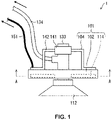
- Fig. 1 shows an example of a configuration of a suction apparatus 1 according to the present embodiment.
- the suction apparatus 1 can be used as a mobile robot for conveying an object.
- the suction apparatus 1 includes: a sensor assembly 101; a suction portion 112 configured to hold an object by suction with negative pressure; a shaft 133 that supports the suction portion 112 and includes an air passage; and a tube 134 connected to the air passage.
- the sensor assembly 101 is attachable to the suction apparatus 1, and includes a body 102, one or more proximity sensors 114, and a fixture 104.
- the suction portion 112 may be worn and deformed, or cracked, due to a change over time.
- the proximity sensor 114 measures deformation of the suction portion 112.
- a deterioration determination apparatus 11 according to the present embodiment shown in Fig. 5 determines whether or not the suction portion 112 has deteriorated, depending on the deformation of the suction portion 112 in the state in which the suction portion 112 does not hold an object by suction.
- Fig. 1 shows an example of the configuration of the suction apparatus 1.
- Fig. 2 shows an example of the sensor assembly 101 in a cross-sectional view taken along line A-A of Fig. 1 .
- the suction apparatus 1 includes: the sensor assembly 101; the suction portion 112 configured to hold an object by suction with negative pressure; the shaft 133 that supports the suction portion 112 and includes an air passage, and the tube 134 connected to the air passage.
- the suction portion 112 include a suction pad that holds an object by suction with negative pressure.
- the sensor assembly 101 is attachable to the suction apparatus 1, and includes the body 102, one or more proximity sensors 114, and the fixture 104.
- a space through which the shaft 133 passes is formed in the body 102.
- the proximity sensor 114 is disposed on the body 102, and detects that the suction portion 112 is deformed by negative pressure.
- the fixture 104 includes a fixed portion 141 that is fixed to the shaft 133, and a support portion 142 that supports the body 102.
- the proximity sensor 114 may be a sensor capable of measuring a distance to an object at a short distance, or a senser capable of detecting that an object has approached to a certain distance.
- Examples of a detection method of the proximity sensor 114 include a capacitive method, an optical method, an electromagnetic induction method, and an acoustic method such as a sound wave method or an ultrasonic method.
- examples of the capacitive sensor include a self-capacitive sensor and a mutual capacitive sensor.
- the one or more proximity sensors provided in the sensor assembly may be of the same type, or may be of different types.
- the suction portion 112 may also be provided with a strain sensor that detects strain in one or more regions of the suction portion 112.
- the sensor assembly 101 is attachable to the shaft 133 of the suction apparatus 1 that supports the suction portion 112 and has the air passage, and the proximity sensor 114 can be disposed on the suction portion 112.
- the proximity sensor 114 measures the amount of deformation of the suction portion 112 that is deformed by negative pressure.
- the suction apparatus 1 includes the sensor assembly 101, the suction portion (suction pad) 112, and the shaft 133.
- An air passage for sucking in air is provided in the shaft 133.
- the air passage is connected to the suction portion 112 and the tube 134.
- the shaft 133 and a vacuum pump that generates negative pressure may be connected through the tube 134.
- the suction portion 112 of the suction apparatus 1 may be grounded.
- the sensor assembly 101 is preferably attached to the shaft 133 on other end side of the shaft 133, for example.
- the body 102 is preferably disposed at a position close to the suction portion 112, for example.
- the support portion 142 of the fixture 104 extends from the fixed portion 141 toward the suction portion 112.
- the body 102 is disposed on a suction portion 112 side relative to the fixed portion 141, using the support portion 142. With this configuration, it is possible to fix the fixture 104 to the other end side (the opposite side to the suction portion 112) of the shaft 133, and to dispose the sensor assembly 101 at a position close to the suction portion 112.
- a space 105 (not shown) through which the shaft 133 of the suction apparatus 1 passes is formed in the body 102.
- the space 105 may be a hole, or a notch.
- the main body 102 is not in contact with the shaft 133, for example.
- the body 102 may have a circular shape, a quadrangular shape, or an elliptical shape.
- the space 105 may have a circular shape, a quadrangular shape, or an elliptical shape.
- the body 102 and a controller such as a programmable logic controller (PLC) or the deterioration determination apparatus 11 may be connected through a sensor wiring 151.
- PLC programmable logic controller
- the proximity sensor 114 is disposed on the main body 102 along the circumferential direction of the space 105 (the shaft 133).
- a plurality of the proximity sensors 114 are disposed on the body 102 along the circumferential direction of the space 105 (the shaft 133).
- a plurality of the proximity sensors 114 are disposed on the body 102 along the circumferential direction and the radial direction with respect to the space 105 (the shaft 133).
- the space 105 has a quadrangular shape, and the proximity sensor 114 is disposed on the body 102 having a quadrangular outer shape.
- the space 105 has a circular shape, and the proximity sensor 114 is disposed on the body 102 having a quadrangular outer shape.
- the proximity sensor 114 is disposed on a quadrangular body 102 in which the space 105 has a circular shape.
- the proximity sensor 114 is disposed on an elliptical body 102 in which the space 105 has an elliptical shape.
- a plurality of the proximity sensors 114 which are sensor chips, are disposed on the body 102 along the circumferential direction of the space 105 (the shaft 133).
- a plurality of the proximity sensors 114 are disposed on the body 102 along the circumferential direction and the radial direction with respect to the space 105 (the shaft 133).
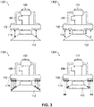
- Fig. 3 illustrates an example of the configuration of the sensor assembly 101.
- the sensor assembly 101 includes the main body 102 shown in the example of the suction apparatus 1a shown in Fig. 2 .
- the proximity sensor 114 provided in the body 102 can measure the amount of displacement of the suction portion 112.
- the proximity sensor 114 is disposed above the suction portion 112.
- the sensor assembly 101 includes the main body 102 shown in the example of the suction apparatus 1c shown in Fig. 2 .
- the plurality of proximity sensors 114 are disposed on the body 102 along the radial direction with respect to the shaft 133.
- the sensor assembly 101 can individually detect displacement at a plurality of positions in the radial direction of the suction portion 112.
- the sensor assembly 101 includes the main body shown in the example of the suction apparatus 1i shown in Fig. 2 .
- the plurality of proximity sensors 114 are disposed on the body 102, along the circumferential direction and the radial direction with respect to the shaft 133.
- a plurality of proximity sensors 114 are disposed in a circle covering the suction portion 112. With this configuration, it is possible to select an appropriate proximity sensor, according to the size of the body.
- the example 1304 shown in Fig. 3 shows a state in which the suction portion 112 has been worn off compared to the example 1303 shown in Fig. 3 .
- the proximity sensors 114 disposed on the radially outer side detect a region on the radially outer side of the suction portion 112 in a normal state as in the example 1303 shown in Fig. 3 , but cannot detect the region on the radially outer side of the suction portion 112 in a worn state (deteriorated state) as in the example 1304 shown in Fig. 3 .
- Fig. 4 shows examples of shapes of a normal state and deteriorated states of the suction portion 112.
- the example 1401 shown in Fig. 4 shows the shape of the suction portion 112 in a normal state, which is unused.
- the example 1402 shown in Fig. 4 shows the shape of the suction portion 112 in which a part of the distal end portion of the suction portion 112 shown in the example 1401 in Fig. 4 is worn or deformed due to deterioration.
- the example 1403 shown in Fig. 4 shows a shape of the suction portion 112 in a state in which the distal end portion of the suction portion 112 in the example 1401 shown in Fig. 4 is worn, and deformed as a whole due to deterioration.
- the example 1404 shown in Fig. 4 shows a shape of the suction portion 112 in a state in which there is a crack in the suction portion 112 of the example 1401 shown in Fig. 4 .
- the proximity sensor 114 outputs different sensor values in the normal state shown in the example 1401 in Fig. 4 and in the deteriorated states shown in the examples 1402 to 1404 in Fig. 4 .
- the sensor value that is output from the proximity sensor 114 changes.
- the electrostatic capacitance of the suction portion 112 changes due to wear
- the sensor value output from the capacitive proximity sensor 114 changes.
- the distance from the proximity sensor 114 to the measurement region may change, and thus the sensor value output from the proximity sensor 114 may change.
- a strain sensor may also be attached to the surface of the suction portion 112. The strain sensor outputs a sensor value that corresponds to the deformation of the suction portion 112. Accordingly, in the deteriorated states shown in examples 1402 to 1404 in Fig. 4 , the sensor value output from the strain sensor changes in accordance with the deformation of the suction portion 112.
- Fig. 5 is a block diagram schematically showing an example of the configuration of the suction system 10 according to the present embodiment.
- the suction system 10 according to the present embodiment includes a suction apparatus 1, a controller 5, a deterioration determination apparatus 11, a display unit 13, and a sound output unit 14.
- the suction apparatus 1 may be a fixed suction apparatus that is fixed at a predetermined position, or may also be a movable suction apparatus including an automated guided vehicle.
- the suction apparatus 1 includes a manipulator unit 111, a suction portion 112, a vacuum pump 12, a proximity sensor 114, a pressure sensor 121, a flow rate sensor 122, and a microphone 123.
- the manipulator unit 111 is driven together with the suction portion 112, under control of the controller 5.
- the manipulator unit 111 is, for example, an articulated robot arm having one or a plurality of joints.
- the suction portion 112 When the suction portion 112 is positioned at a work position by driving of the manipulator unit 111, the suction portion 112 holds an object by suction with negative pressure that corresponds to the driving amount of the vacuum pump 12.
- the suction portion 112 is elastically deformed by negative pressure, and is brought into intimate contact with an object. In this manner, the suction portion 112 holds the object.
- the vacuum pump 12 generates negative pressure that corresponds to the driving amount, and provides the generated negative pressure to the suction portion 112.
- the suction apparatus 1 in the suction system 10 includes the vacuum pump 12
- the suction apparatus 1 in the suction system 10 does not necessarily have to include the vacuum pump 12, and for example, the vacuum pump 12 may also be provided outside the suction apparatus 1 and the suction system 10.
- the controller 5 controls the driving amount of the vacuum pump 12, so that the same effect as in the above-described example can be achieved.
- the pressure sensor 121 measures pressure P inside the suction portion 112 in which negative pressure is generated using the vacuum pump 12, and outputs information indicating the pressure P to the information obtainment unit 113.
- the flow rate sensor 122 is disposed with respect to, for example, the tube 134, measures a flow rate of air flowing through the tube 134, and outputs information indicating the flow rate to the information obtainment unit 113.
- the microphone 123 is disposed near the tube 134, and measures sound generated due to flow of air. Examples of the sound include a sound generated when an object is held by suction with the suction portion 112 and air flowing into the air passage from a portion between the object and the suction portion 112 is blocked, and a sound generated due to air flowing through the tube. The sound measured by the microphone 123 varies depending on the flow rate of air. The microphone 123 outputs information on the measured sound to the information obtainment unit 113, as sound data.
- the controller 5 includes, for example, a central processing unit (CPU), and a random access memory (RAM) or a read only memory (ROM), and performs control in response to an information process.
- the controller 5 controls the manipulator unit 111.
- the controller 5 moves the suction portion 112 through the manipulator unit 111.
- the controller 5 drives the manipulator unit 111 so that the suction portion 112 is positioned at a work position where the suction portion 112 can hold an object by suction.
- the controller 5 may also operate the manipulator unit 111 so that the angle of the suction portion 112 with respect to the object reaches a predetermined angle, after the suction portion 112 is positioned at the work position.
- the controller 5 controls the vacuum pump 12. In this manner, the controller 5 drives the vacuum pump 12, and causes the suction portion 112 to hold an object by suction.
- the controller 5 outputs, to the deterioration determination apparatus 11, information on the mass of an object to be held by suction and information whether or not the suction portion 112 is currently holding an object by suction.
- the controller 5 included in the suction system 10 is provided outside the suction apparatus 1 and the deterioration determination apparatus 11.
- the present invention is not limited to the above configuration, and for example, the suction apparatus 1 may also include the controller 5, or the deterioration determination apparatus 11 may also include the controller 5.
- the suction apparatus 1 may be configured to be operated by a battery, or may also be configured to be supplied with electric power from the outside of the suction apparatus 1 through a power cord.
- the deterioration determination apparatus 11 includes an information obtainment unit 113, a deterioration determination unit 115, a storage unit 116, a lifetime prediction unit 117, and a notification control unit 118.
- the information obtainment unit 113 obtains information on deformation of one or more regions of the suction portion 112.
- the information obtainment unit 113 preferably obtains information on deformation of a plurality of regions of the suction portion 112. In this manner, the deterioration determination apparatus 11 can strictly determine a deteriorated region of the suction portion 112.
- the information obtainment unit 113 obtains, for example, data indicating the deformation amount of the suction portion 112 from the proximity sensor 114, and specifies the deformation amount of the suction portion 112. Also, the information obtainment unit 113 obtains, from the pressure sensor 121, information indicating pressure.
- the information obtainment unit 113 obtains, from the flow rate sensor 122, information indicating the flow rate of air flowing through the tube 134.
- the information obtainment unit 113 obtains sound data from the microphone 123. Furthermore, the information obtainment unit 113 obtains, from the controller 5, information indicating whether or not the suction portion 112 is currently holding an object by suction. The information obtainment unit 113 outputs, to the deterioration determination unit 115, the information indicating the deformation amount, the information indicating the pressure, the information indicating the flow rate of air, the sound data, and the information indicating whether or not the suction portion 112 is currently holding an object by suction.
- the information obtainment unit 113 outputs, to the controller 5, deformation data such as deformation amount, deformation speed, or deformation acceleration of the suction portion 112.
- the deterioration determination unit 115 determines whether or not the suction portion 112 has deteriorated, depending on deformation of one or more regions of the suction portion 112 in a state in which the suction portion 112 does not hold an object by suction.
- the deterioration determination unit 115 outputs the determination result to the notification control unit 118.
- the data (the information indicating pressure, the information indicating deformation amount, the information indicating the flow rate of air, and the sound data) processed by the deterioration determination unit 115 is output to and stored in the storage unit 116.
- the deterioration determination unit 115 determines whether or not the suction portion 112 has deteriorated, depending on whether or not deformation of one or more regions of the suction portion 112 in the state in which the suction portion 112 does not hold an object by suction is within a normal range that is set for the one or more regions of the suction portion 112.
- the normal range may be a range including a value set in advance as a value indicating that the suction portion is normal, or a range including a value when the suction portion is in an initial state.
- the initial state refers to an unused state of the suction portion 112 in which the suction portion 112 has not applied suction after the suction portion 112 was attached to the deterioration determination apparatus 11.
- the deterioration determination unit 115 may also calculate a ratio of the deformation of a plurality of regions of the suction portion 112 in the state in which the suction portion 112 does not hold an object by suction, based on information on deformation of the plurality of regions of the suction portion 112.
- a metal piece or the like is attached to a partial region of the suction portion 112
- a deviation occurs in the sensor values of the proximity sensors 114, even when the suction portion 112 is in a normal state.
- the deterioration determination unit 115 may also calculate a ratio that is corrected by the sensor value obtained when the suction portion 112 is in a normal state.
- the deterioration determination unit 115 may determine whether or not the suction portion 112 has deteriorated, according to whether or not d1/d1o:d2/d2o:d3/d3o is within a normal range.
- the deterioration determination unit 115 may determine that the ratio of d1/d1o:d2/d2o:d3/d3o is within a normal range.
- the deterioration determination unit 115 may also determine that the deformation ratio d1:d2:d3 of each region is within a normal range.
- the deterioration determination unit 115 determines whether or not the suction portion 112 has deteriorated, depending on the calculated ratio.
- the deterioration determination unit 115 determines whether or not the suction portion 112 has deteriorated, depending on whether or not the calculated ratio is within a normal range that has been set for a plurality of regions of the suction portion 112.
- the normal range may be a range including a ratio that has been set in advance as a ratio indicating that the suction portion is normal, or a range including a ratio when the suction portion is in an initial state.
- the deterioration determination unit 115 outputs, to the controller 5, a signal whether or not to continue the operation. When it is determined that the suction portion 112 has not deteriorated, the deterioration determination unit 115 outputs, to the controller 5, a signal for continuing the operation. When it is determined that the suction portion 112 has deteriorated, the deterioration determination unit 115 outputs, to the controller 5, a signal for stopping the operation.
- the storage unit 116 stores information on deformation of the one or more regions of the suction portion 112 obtained by the deterioration determination unit 115 from the information obtainment unit 113, the date and time when deformation is measured, and a result of the determination performed by the deterioration determination unit 115.
- the storage unit 116 is, for example, an auxiliary storage device such as a hard disk drive or a solid state drive.
- the lifetime prediction unit 117 obtains, from the storage unit 116, time-series information in a predetermined period indicating deformation of the one or more regions of the suction portion 112 in the state in which the suction portion 112 does not hold an object by suction.
- the lifetime prediction unit 117 predicts the lifetime of the suction portion 112 from a temporal change in the deformation of the one or more regions of the suction portion 112 in the state in which the suction portion 112 does not hold an object by suction.
- the lifetime prediction unit 117 outputs, to the controller 5, a signal indicating whether or not to continue the operation, depending on the predicted lifetime of the suction portion 112.
- the lifetime prediction unit 117 may output, to the controller 5, a signal for stopping the operation when the suction portion 112 reaches the end of its lifetime, or may also output, to the controller 5, a signal for stopping the operation before a predetermined period from the end of the lifetime of the suction portion 112.
- the lifetime prediction unit 117 may also output, to the controller 5, a signal for stopping the operation when the suction portion 112 holds an object by suction another 20 times.
- the notification control unit 118 may notify at least one of the display unit 13 and the sound output unit 14 that the suction portion 112 has deteriorated.
- the notification control unit 118 may cause, for example, for notifying deterioration of the suction portion 112, the display unit 13 to emit light of a predetermined color or display an image for notifying deterioration of the suction portion 112, or may also cause the sound output unit 14 to output a predetermined sound for notifying deterioration of the suction portion 112.
- the notification control unit 118 may also notify at least one of the display unit 13 and the sound output unit 14 that the lifetime of the suction portion 112 predicted by the lifetime prediction unit 117 is close to its end.
- the notification control unit 118 may also notify, for example, at least one of the display unit 13 and the sound output unit 14 that the suction portion 112 will reach the end of its lifetime after a predetermined period has elapsed, at a point in time before the predetermined period.
- the notification control unit 118 may also cause the display unit 13 to emit light of a predetermined color or display an image, for notifying that the suction portion 112 will reach the end of its lifetime after a predetermined period has elapsed.
- the notification control unit 118 may also cause the sound output unit 14 to output a predetermined sound, for notifying that the suction portion 112 will reach the end of its lifetime after a predetermined period has elapsed.
- the predetermined period is not limited to a specific period, but is, for example, one month.
- the display unit 13 displays light or an image, in accordance with an instruction transmitted from the notification control unit 118.
- the display unit 13 is not limited to a specific device as long as it emits light or displays an image, and examples of the display unit 13 include a lamp or a display.
- the sound output unit 14 outputs sound, in accordance with an instruction transmitted from the notification control unit 118. Examples of the sound include a buzzer sound, for example.
- the sound output unit 14 is not limited to a specific device as long as it outputs sound, and examples of the sound output unit 14 include a speaker.
- Fig. 6 is a flow chart showing how the suction system 10 depending on the embodiment of the present invention operates.
- step S11 the controller 5 included in the suction apparatus 1 controls the vacuum pump 12 so as not to generate negative pressure, thereby stopping suction.
- the proximity sensor 114 can detect deformation of one or more regions of the suction portion 112 in a state in which the suction portion 112 does not hold an object by suction.
- a signal indicating that the suction portion 112 is not holding an object by suction is input from the controller 5 to the information obtainment unit 113. In this step, it is also possible that suction is not stopped, as long as the suction portion 112 is not holding an object by suction.
- step S12 information obtainment step
- the information obtainment unit 113 included in the deterioration determination apparatus 11 obtains, from the proximity sensor 114, information on the deformation of the one or more regions of the suction portion 112 in the state in which the suction portion 112 does not hold an object by suction.
- step S14 the deterioration determination unit 115 included in the deterioration determination apparatus 11 determines whether or not the suction portion 112 has deteriorated, in accordance with the deformation of the one or more regions of the suction portion 112 in the state in which the suction portion 112 does not hold an object by suction.
- step S14 the deterioration determination unit 115 determines whether or not the suction portion 112 has deteriorated, depending on whether or not the deformation of the one or more regions of the suction portion 112 in the state in which the suction portion 112 does not hold an object by suction is within a normal range that is set for the one or more regions of the suction portion 112.
- step S14 when the deformation of the one or more region of the suction portion 112 in the state in which the suction portion 112 does not hold an object by suction is within a normal range, the deterioration determination unit 115 determines that the suction portion 112 has not deteriorated, that is to say, the deterioration determination unit 115 determines that the suction portion 112 is in a normal condition. In step S14, when the deformation of the one or more regions of the suction portion 112 is outside the normal range, the deterioration determination unit 115 determines that the suction portion 112 has deteriorated.
- step S14 When the deterioration determination unit 115 determines that the suction portion 112 has not deteriorated (YES in step S14), the process proceeds to step S15. In contrast, when the deterioration determination unit 115 determines that the suction portion 112 has deteriorated (NO in step S14), the process proceeds to step S18.
- step S15 the controller 5 included in the suction apparatus 1 causes the vacuum pump 12 to generate negative pressure that corresponds to the driving amount. In this manner, the vacuum pump 12 causes the suction portion 112 to hold an object by suction. A signal indicating that the suction portion 112 is holding an object by suction is input from the controller 5 to the information obtainment unit 113.
- step S16 the information obtainment unit 113 included in the deterioration determination apparatus 11 obtains, from the pressure sensor 121, the internal pressure of the suction portion 112 currently holding the object by suction.
- the information obtainment unit 113 may also obtain, from the flow rate sensor 122, the flow rate of air flowing through the tube 134, instead of obtaining the pressure.
- the information obtainment unit 113 may also obtain, from the microphone 123, the sound generated due to the flow of air.
- step S17 the deterioration determination unit 115 determines whether or not the suction portion 112 has deteriorated, depending on the pressure obtained in step S16.
- step S17 the deterioration determination unit 115 determines whether or not the suction portion 112 is in an abnormal condition, according to whether or not the pressure obtained in step S16 is within a normal range that is set for the suction portion 112.
- an abnormal condition in the suction portion 112 include not only deterioration, but also a state in which dust or the like is sandwiched between the suction portion 112 and an object.
- step S17 when the pressure obtained in step S16 is within the normal range, the deterioration determination unit 115 determines that the suction portion 112 is not in an abnormal condition. In contrast, in step S17, when the pressure obtained in step S16 is outside the normal range, the deterioration determination unit 115 determines that the suction portion 112 is in an abnormal condition.
- a crack occurs in the suction portion 112, for example, air flows into the suction portion 112, and thus the decrease in pressure is reduced.
- the suction portion 112 is deformed due to deterioration, the suction portion 112 does not come into intimate contact with an object, and air may flow into the suction portion 112. Also, when dust or the like is sandwiched between the suction portion 112 and an object, the suction portion 112 does not come into intimate contact with the object, and air may flow into the suction portion 112.
- step S17 When the deterioration determination unit 115 determines that the suction portion 112 is not in an abnormal condition (YES in step S17), the deterioration determination unit 115 ends the deterioration determination process. In contrast, when the deterioration determination unit 115 determines that the suction portion 112 is in an abnormal condition (NO in step S17), the process proceeds to step S19.
- step S17 when the information obtainment unit 113 obtains the flow rate of air instead of pressure in step S16, the deterioration determination unit 115 may also determine whether the suction portion 112 is in an abnormal condition, according to the flow rate. Similarly, when the information obtainment unit 113 obtains sound instead of pressure in step S16, the deterioration determination unit 115 may also determine whether the suction portion 112 is in an abnormal condition, according to the sound. When air flows into the suction portion 112, for example, the flow rate of air or the sound increases due to the flow of air. In order to determine whether or not the suction portion 112 is in an abnormal condition, the suction system 10 may include any one of the pressure sensor 121, the flow rate sensor 122, and the microphone 123 (the other two devices may be omitted).
- step S18 when the deterioration determination unit 115 determines that the suction portion 112 has deteriorated, the notification control unit 118 notifies at least one of the display unit 13 and the sound output unit 14 that the suction portion 112 has deteriorated.
- step S19 when the deterioration determination unit 115 determines that the suction portion 112 is in an abnormal condition, the notification control unit 118 notifies at least one of the display unit 13 and the sound output unit 14 that the suction portion 112 is in an abnormal condition.
- Fig. 7 is a flow chart showing how a suction system according to another embodiment of the present invention operates. Steps S11, S12, and S15 to S18 are as described in "operation example 1", and thus only different points will be described.
- step S22 information obtainment step
- the information obtainment unit 113 included in the deterioration determination apparatus 11 obtains, from the proximity sensor 114, information on deformation of a plurality of regions of the suction portion 112 in the state in which the suction portion 112 does not hold an object by suction.
- step S23 the deterioration determination unit 115 calculates a ratio of the deformation of the plurality of regions of the suction portion 112, based on the information on deformation of the plurality of regions of the suction portion 112 in the state in which the suction portion 112 does not hold an object by suction.
- step S24 deterioration determination step
- the deterioration determination unit 115 determines whether or not the suction portion 112 has deteriorated, depending on the calculated ratio.
- step S24 the deterioration determination unit 115 determines whether or not the suction portion 112 has deteriorated, depending on whether or not the calculated ratio is within a normal range that has been set for the plurality of regions of the suction portion 112.
- step S24 when the calculated ratio is within a normal range, the deterioration determination unit 115 determines that the suction portion 112 has not deteriorated. In contrast, in step S24, when the calculated ratio is outside the normal range, the deterioration determination unit 115 determines that the suction portion 112 has deteriorated.
- step S24 When the deterioration determination unit 115 determines that the suction portion 112 has not deteriorated (YES in step S24), the process proceeds to step S15. In contrast, when the deterioration determination unit 115 determines that the suction portion 112 has deteriorated (NO in step S24), the process proceeds to step S18.
- the suction portion 112 it is possible to strictly determine a deteriorated region of the suction portion 112, by obtaining information on deformation of a plurality of regions of the suction portion 112 in a state in which the suction portion 112 does not hold an object by suction. Furthermore, by calculating the ratio of deformation of the plurality of regions of the suction portion 112, and determining whether or not the suction portion 112 has deteriorated according to the calculated ratio, it is possible to accurately determine whether or not the suction portion 112 has deteriorated, even if the sensor value fluctuates due to the influence of the environment such as temperature.
- the lifetime prediction unit 117 obtains, from the storage unit 116, information on deformation of one or more regions of the suction portion 112 in a state in which the suction portion 112 does not hold an object by suction, and predicts the lifetime of the suction portion 112 based on a temporal change in deformation of the one or more regions.
- the lifetime prediction unit 117 can predict the lifetime of the suction portion 112, based on a temporal change of a sensor value due to deformation caused by deterioration or due to wear.
- Fig. 8 shows the relationship between the elapsed time from the start of use of the suction portion 112 and sensor values.
- the lifetime prediction unit 117 obtains, for example, from the storage unit 116, sensor values measured by the proximity sensor 114 from the start of use of the suction portion 112 to the time point t i .
- the lifetime prediction unit 117 obtains a curve indicating a predicted change of sensor values, based on the obtained sensor values from the start of use of the suction portion 112 to the time point t i .
- the lifetime prediction unit 117 obtains, for example, a curve indicating the predicted change of sensor values using the sensor values in a predetermined period up to time point t i .
- the lifetime prediction unit 117 can predict the replacement time t e from the intersection of the obtained curve and the threshold value in the normal range.
- the lifetime prediction unit 117 may also predict the lifetime of the suction portion 112 using a total value or an average value of sensor output values of the proximity sensors 114, or the number of proximity sensors 114 whose outputs are ON.
- the fact that the output of a proximity sensor 114 is ON means that an object is present within a certain distance.
- Control blocks included in the deterioration determination apparatus 11 may be implemented by a logic circuit (hardware) formed in an integrated circuit (IC chip) or the like, or may also be implemented by software.
- the deterioration determination apparatus 11 includes a computer that executes instructions of a program, which is software for implementing the functions.
- the computer includes, for example, one or more processors, and a computer-readable recording medium storing the program.
- the processor reads the program from the recording medium and executes the program, thereby achieving the object of the present invention.
- a central processing unit CPU
- the recording medium a "non-transitory tangible medium" such as a read only memory (ROM), a tape, a disk, a card, a semiconductor memory, or a programmable logic circuit can be used.
- the deterioration determination apparatus 11 may further include, for example, a random access memory (RAM) that develops the program.
- the program may be supplied to the computer through any transmission medium (for example, a communication network, or a broadcast wave) capable of transmitting the program.
- a transmission medium for example, a communication network, or a broadcast wave
- One aspect of the present invention can be also achieved in the form of a data signal embedded in a carrier wave in which the program is embodied by electronic transmission.
- a deterioration determination apparatus includes: an information obtainment unit configured to obtain information on deformation of one or more regions of a suction portion configured to hold an object by suction with negative pressure; and a deterioration determination unit configured to determine whether or not the suction portion has deteriorated, depending on the deformation of the one or more regions of the suction portion in a state in which the suction portion does not hold an object by suction.
- the suction portion by detecting the deformation of the one or more regions of the suction portion in the state in which the suction portion does not hold an object by suction, it is possible to detect how much the suction portion has deteriorated based on the degree of deformation of the suction portion. As a result, it is possible to determine whether or not the suction portion has deteriorated, in accordance with the degree of deformation of the suction portion.
- the deterioration determination unit may determine whether or not the suction portion has deteriorated, depending on whether or not the deformation of one or more regions of the suction portion in the state in which the suction portion does not hold an object by suction is within a normal range that is set for the one or more regions of the suction portion.
- the information obtainment unit may obtain information on deformation of a plurality of regions of the suction portion in the state in which the suction portion does not hold an object by suction, and the deterioration determination unit may calculate a ratio of the deformation of the plurality of regions of the suction portion based on the information on the deformation of the plurality of regions of the suction portion in the state in which the suction portion does not hold an object by suction, and determine whether the suction portion has deteriorated, depending on the ratio.
- the suction portion it is possible to strictly determine a deteriorated region of the suction portion, by obtaining information on the deformation of the plurality of regions of the suction portion in the state in which the suction portion does not hold an object by suction. Furthermore, by calculating the ratio of the deformation of the plurality of regions of the suction portion, and determining whether or not the suction portion has deteriorated based on the calculated ratio, it is possible to accurately determine whether or not the suction portion has deteriorated, even if the sensor value fluctuates due to the influence of the environment such as temperature.
- the deterioration determination apparatus may further include a lifetime prediction unit configured to predict a lifetime of the suction portion, based on a temporal change in the deformation of the one or more regions of the suction portion in the state in which the suction portion does not hold an object by suction.
- the information obtainment unit may obtain information indicating an internal pressure of the suction portion currently holding the object by suction, information indicating the flow rate of air flowing through a tube connected to an air passage, or, as sound data, information regarding sound generated due to the flow of air, and the deterioration determination unit may determine whether or not the suction portion is in an abnormal condition, depending on the pressure, the flow rate of air, or the sound.
- a deterioration determination method includes: an information obtainment step of obtaining information on deformation of one or more regions of a suction portion configured to hold an object by suction with negative pressure; and a deterioration determination step of determining whether or not the suction portion has deteriorated, depending on the deformation of the one or more regions of the suction portion in a state in which the suction portion does not hold an object by suction.
- the deterioration determination apparatus may be achieved by a computer.
- the scope of the present invention may also include a control program for the deterioration determination apparatus that causes a computer to operate as the deterioration determination apparatus by causing the computer to operate as the units (software elements) included in the deterioration determination apparatus, and a computer-readable recording medium that records the control program.
Landscapes
- Engineering & Computer Science (AREA)
- Robotics (AREA)
- Mechanical Engineering (AREA)
- Physics & Mathematics (AREA)
- General Physics & Mathematics (AREA)
- Human Computer Interaction (AREA)
- Manufacturing & Machinery (AREA)
- Automation & Control Theory (AREA)
- Manipulator (AREA)
Abstract
Description
- The present invention relates to a suction apparatus.
- A work robot that includes a robot arm including a plurality of arm members is known in the related art.
Patent Document 1 discloses, for example, a funnel-shaped suction member having an opening for sucking in external air and holding a workpiece by suction, in which a conductive wire for detecting breakage due to disconnection is provided around the opening. - Patent Document 1:
JP 2015-150622A - However, the above-described related art has a problem that it is not versatile because it is necessary to manufacture a dedicated suction portion.
- An aspect of the present invention has been made in view of such circumstances, and an object of the present invention is to provide a suction apparatus capable of easily determining deterioration of a suction portion.
- In order to solve the above-described problem, the present invention employs the following configurations.
- A deterioration determination apparatus according to an aspect of the present disclosure includes: an information obtainment unit configured to obtain information on deformation of one or more regions of a suction portion configured to hold an object by suction with negative pressure; and a deterioration determination unit configured to determine whether the suction portion has deteriorated, depending on the deformation of the one or more regions of the suction portion in a state in which the suction portion does not hold an object by suction.
- A deterioration determination method according to an aspect of the present disclosure includes: an information obtainment step of obtaining information on deformation of one or more regions of a suction portion configured to hold an object by suction with negative pressure; and a deterioration determination step of determining whether the suction portion has deteriorated, depending on the deformation of the one or more regions of the suction portion in a state in which the suction portion does not hold an object by suction.
- According to an embodiment of the present invention, it is possible to provide a suction apparatus capable of easily determining whether or not a suction portion has deteriorated.
-
- Fig. 1
- shows an example of a configuration of a suction apparatus according to an embodiment of the present invention.
- Fig. 2
- shows an example of a cross-sectional view taken along line A-A of
Fig. 1 . - Fig. 3
- shows an example of a configuration of a sensor assembly included in the suction apparatus according to the embodiment of the present invention.
- Fig. 4
- shows an example of shapes of a normal state and a deteriorated state of a suction portion included in the suction apparatus according to the embodiment of the present invention.
- Fig. 5
- is a block diagram schematically showing an example of a configuration of a suction system according to the embodiment of the present invention.
- Fig. 6
- is a flow chart showing how the suction system according to the embodiment of the present invention operates.
- Fig. 7
- is a flow chart showing how a suction system according to another embodiment of the present invention operates.
- Fig. 8
- shows the relationship between the elapsed time from the start of use of the suction portion and sensor values.
- Hereinafter, an embodiment according to one aspect of the present invention (hereinafter, also referred to as "the present embodiment") will be described with reference to the drawings.
-
Fig. 1 shows an example of a configuration of asuction apparatus 1 according to the present embodiment. Thesuction apparatus 1 can be used as a mobile robot for conveying an object. - As shown in
Fig. 1 , thesuction apparatus 1 includes: asensor assembly 101; asuction portion 112 configured to hold an object by suction with negative pressure; ashaft 133 that supports thesuction portion 112 and includes an air passage; and atube 134 connected to the air passage. - The
sensor assembly 101 is attachable to thesuction apparatus 1, and includes abody 102, one ormore proximity sensors 114, and afixture 104. - The
suction portion 112 may be worn and deformed, or cracked, due to a change over time. Theproximity sensor 114 measures deformation of thesuction portion 112. Adeterioration determination apparatus 11 according to the present embodiment shown inFig. 5 determines whether or not thesuction portion 112 has deteriorated, depending on the deformation of thesuction portion 112 in the state in which thesuction portion 112 does not hold an object by suction. -
Fig. 1 shows an example of the configuration of thesuction apparatus 1.Fig. 2 shows an example of thesensor assembly 101 in a cross-sectional view taken along line A-A ofFig. 1 . - As shown in
Fig. 1 , thesuction apparatus 1 includes: thesensor assembly 101; thesuction portion 112 configured to hold an object by suction with negative pressure; theshaft 133 that supports thesuction portion 112 and includes an air passage, and thetube 134 connected to the air passage. Examples of thesuction portion 112 include a suction pad that holds an object by suction with negative pressure. - The
sensor assembly 101 is attachable to thesuction apparatus 1, and includes thebody 102, one ormore proximity sensors 114, and thefixture 104. A space through which theshaft 133 passes is formed in thebody 102. Theproximity sensor 114 is disposed on thebody 102, and detects that thesuction portion 112 is deformed by negative pressure. Thefixture 104 includes afixed portion 141 that is fixed to theshaft 133, and asupport portion 142 that supports thebody 102. - The
proximity sensor 114 may be a sensor capable of measuring a distance to an object at a short distance, or a senser capable of detecting that an object has approached to a certain distance. Examples of a detection method of theproximity sensor 114 include a capacitive method, an optical method, an electromagnetic induction method, and an acoustic method such as a sound wave method or an ultrasonic method. Also, examples of the capacitive sensor include a self-capacitive sensor and a mutual capacitive sensor. The one or more proximity sensors provided in the sensor assembly may be of the same type, or may be of different types. Instead of theproximity sensor 114 included in thesensor assembly 101, thesuction portion 112 may also be provided with a strain sensor that detects strain in one or more regions of thesuction portion 112. - The
sensor assembly 101 is attachable to theshaft 133 of thesuction apparatus 1 that supports thesuction portion 112 and has the air passage, and theproximity sensor 114 can be disposed on thesuction portion 112. Theproximity sensor 114 measures the amount of deformation of thesuction portion 112 that is deformed by negative pressure. - In the example of
Fig. 1 , thesuction apparatus 1 includes thesensor assembly 101, the suction portion (suction pad) 112, and theshaft 133. An air passage for sucking in air is provided in theshaft 133. The air passage is connected to thesuction portion 112 and thetube 134. Theshaft 133 and a vacuum pump that generates negative pressure may be connected through thetube 134. Thesuction portion 112 of thesuction apparatus 1 may be grounded. - Because the
suction portion 112 is disposed on one end side of theshaft 133, thesensor assembly 101 is preferably attached to theshaft 133 on other end side of theshaft 133, for example. However, in order to accurately detect the deformation of thesuction portion 112, thebody 102 is preferably disposed at a position close to thesuction portion 112, for example. - The
support portion 142 of thefixture 104 extends from the fixedportion 141 toward thesuction portion 112. Thebody 102 is disposed on asuction portion 112 side relative to the fixedportion 141, using thesupport portion 142. With this configuration, it is possible to fix thefixture 104 to the other end side (the opposite side to the suction portion 112) of theshaft 133, and to dispose thesensor assembly 101 at a position close to thesuction portion 112. - A space 105 (not shown) through which the
shaft 133 of thesuction apparatus 1 passes is formed in thebody 102. Thespace 105 may be a hole, or a notch. Themain body 102 is not in contact with theshaft 133, for example. Thebody 102 may have a circular shape, a quadrangular shape, or an elliptical shape. In addition, thespace 105 may have a circular shape, a quadrangular shape, or an elliptical shape. Thebody 102 and a controller such as a programmable logic controller (PLC) or thedeterioration determination apparatus 11 may be connected through asensor wiring 151. - In the example of a
suction apparatus 1a inFig. 2 , theproximity sensor 114 is disposed on themain body 102 along the circumferential direction of the space 105 (the shaft 133). In the example of asuction apparatus 1b inFIG. 2 , a plurality of theproximity sensors 114 are disposed on thebody 102 along the circumferential direction of the space 105 (the shaft 133). In the example of asuction apparatus 1c inFig. 2 , a plurality of theproximity sensors 114 are disposed on thebody 102 along the circumferential direction and the radial direction with respect to the space 105 (the shaft 133). In the example of asuction apparatus 1d inFig. 2 , thespace 105 has a quadrangular shape, and theproximity sensor 114 is disposed on thebody 102 having a quadrangular outer shape. In the example of asuction apparatus 1e inFig. 2 , thespace 105 has a circular shape, and theproximity sensor 114 is disposed on thebody 102 having a quadrangular outer shape. In the example of asuction apparatus 1f inFig. 2 , theproximity sensor 114 is disposed on aquadrangular body 102 in which thespace 105 has a circular shape. In the example of asuction apparatus 1g inFig. 2 , theproximity sensor 114 is disposed on anelliptical body 102 in which thespace 105 has an elliptical shape. In the example of asuction apparatus 1h inFig. 2 , a plurality of theproximity sensors 114, which are sensor chips, are disposed on thebody 102 along the circumferential direction of the space 105 (the shaft 133). In the example of a suction apparatus 1i inFig. 2 , a plurality of theproximity sensors 114 are disposed on thebody 102 along the circumferential direction and the radial direction with respect to the space 105 (the shaft 133). -
Fig. 3 illustrates an example of the configuration of thesensor assembly 101. In the example 1301 shown inFig. 3 , thesensor assembly 101 includes themain body 102 shown in the example of thesuction apparatus 1a shown inFig. 2 . Theproximity sensor 114 provided in thebody 102 can measure the amount of displacement of thesuction portion 112. Theproximity sensor 114 is disposed above thesuction portion 112. In the example 1302 shown inFig. 3 , thesensor assembly 101 includes themain body 102 shown in the example of thesuction apparatus 1c shown inFig. 2 . The plurality ofproximity sensors 114 are disposed on thebody 102 along the radial direction with respect to theshaft 133. With this configuration, thesensor assembly 101 can individually detect displacement at a plurality of positions in the radial direction of thesuction portion 112. In the example 1303 shown inFig. 3 , thesensor assembly 101 includes the main body shown in the example of the suction apparatus 1i shown inFig. 2 . The plurality ofproximity sensors 114 are disposed on thebody 102, along the circumferential direction and the radial direction with respect to theshaft 133. When thesensor assembly 101 includes thebody 102 of the examples of thesuction apparatuses 1c or 1i shown inFig. 2 , then a plurality ofproximity sensors 114 are disposed in a circle covering thesuction portion 112. With this configuration, it is possible to select an appropriate proximity sensor, according to the size of the body. The example 1304 shown inFig. 3 shows a state in which thesuction portion 112 has been worn off compared to the example 1303 shown inFig. 3 . Theproximity sensors 114 disposed on the radially outer side detect a region on the radially outer side of thesuction portion 112 in a normal state as in the example 1303 shown inFig. 3 , but cannot detect the region on the radially outer side of thesuction portion 112 in a worn state (deteriorated state) as in the example 1304 shown inFig. 3 . -
Fig. 4 shows examples of shapes of a normal state and deteriorated states of thesuction portion 112. The example 1401 shown inFig. 4 shows the shape of thesuction portion 112 in a normal state, which is unused. The example 1402 shown inFig. 4 shows the shape of thesuction portion 112 in which a part of the distal end portion of thesuction portion 112 shown in the example 1401 inFig. 4 is worn or deformed due to deterioration. The example 1403 shown inFig. 4 shows a shape of thesuction portion 112 in a state in which the distal end portion of thesuction portion 112 in the example 1401 shown inFig. 4 is worn, and deformed as a whole due to deterioration. The example 1404 shown inFig. 4 shows a shape of thesuction portion 112 in a state in which there is a crack in thesuction portion 112 of the example 1401 shown inFig. 4 . Theproximity sensor 114 outputs different sensor values in the normal state shown in the example 1401 inFig. 4 and in the deteriorated states shown in the examples 1402 to 1404 inFig. 4 . When the distance between theproximity sensor 114 and thesuction portion 112 changes due to deterioration, the sensor value that is output from theproximity sensor 114 changes. Also, when the electrostatic capacitance of thesuction portion 112 changes due to wear, the sensor value output from thecapacitive proximity sensor 114 changes. When a crack occurs in the measurement region of theproximity sensor 114 in thesuction portion 112, the distance from theproximity sensor 114 to the measurement region may change, and thus the sensor value output from theproximity sensor 114 may change. Instead of theproximity sensor 114, a strain sensor may also be attached to the surface of thesuction portion 112. The strain sensor outputs a sensor value that corresponds to the deformation of thesuction portion 112. Accordingly, in the deteriorated states shown in examples 1402 to 1404 inFig. 4 , the sensor value output from the strain sensor changes in accordance with the deformation of thesuction portion 112. - Next, an example of a hardware configuration of the
suction system 10 including the deterioration determination apparatus according to the present embodiment will be described with reference toFig. 5 . -
Fig. 5 is a block diagram schematically showing an example of the configuration of thesuction system 10 according to the present embodiment. In the example ofFig. 5 , thesuction system 10 according to the present embodiment includes asuction apparatus 1, acontroller 5, adeterioration determination apparatus 11, adisplay unit 13, and asound output unit 14. In the present embodiment, thesuction apparatus 1 may be a fixed suction apparatus that is fixed at a predetermined position, or may also be a movable suction apparatus including an automated guided vehicle. - The
suction apparatus 1 includes amanipulator unit 111, asuction portion 112, avacuum pump 12, aproximity sensor 114, apressure sensor 121, aflow rate sensor 122, and amicrophone 123. - The
manipulator unit 111 is driven together with thesuction portion 112, under control of thecontroller 5. Themanipulator unit 111 is, for example, an articulated robot arm having one or a plurality of joints. - When the
suction portion 112 is positioned at a work position by driving of themanipulator unit 111, thesuction portion 112 holds an object by suction with negative pressure that corresponds to the driving amount of thevacuum pump 12. Thesuction portion 112 is elastically deformed by negative pressure, and is brought into intimate contact with an object. In this manner, thesuction portion 112 holds the object. - The
vacuum pump 12 generates negative pressure that corresponds to the driving amount, and provides the generated negative pressure to thesuction portion 112. Here, an example in which thesuction apparatus 1 in thesuction system 10 includes thevacuum pump 12 is described. However, in the present embodiment, thesuction apparatus 1 in thesuction system 10 does not necessarily have to include thevacuum pump 12, and for example, thevacuum pump 12 may also be provided outside thesuction apparatus 1 and thesuction system 10. Also with this configuration, thecontroller 5 controls the driving amount of thevacuum pump 12, so that the same effect as in the above-described example can be achieved. - The
pressure sensor 121 measures pressure P inside thesuction portion 112 in which negative pressure is generated using thevacuum pump 12, and outputs information indicating the pressure P to the information obtainmentunit 113. - The
flow rate sensor 122 is disposed with respect to, for example, thetube 134, measures a flow rate of air flowing through thetube 134, and outputs information indicating the flow rate to the information obtainmentunit 113. - The
microphone 123 is disposed near thetube 134, and measures sound generated due to flow of air. Examples of the sound include a sound generated when an object is held by suction with thesuction portion 112 and air flowing into the air passage from a portion between the object and thesuction portion 112 is blocked, and a sound generated due to air flowing through the tube. The sound measured by themicrophone 123 varies depending on the flow rate of air. Themicrophone 123 outputs information on the measured sound to the information obtainmentunit 113, as sound data. - The
controller 5 includes, for example, a central processing unit (CPU), and a random access memory (RAM) or a read only memory (ROM), and performs control in response to an information process. In addition, thecontroller 5 controls themanipulator unit 111. In this manner, thecontroller 5 moves thesuction portion 112 through themanipulator unit 111. Specifically, thecontroller 5 drives themanipulator unit 111 so that thesuction portion 112 is positioned at a work position where thesuction portion 112 can hold an object by suction. Also, thecontroller 5 may also operate themanipulator unit 111 so that the angle of thesuction portion 112 with respect to the object reaches a predetermined angle, after thesuction portion 112 is positioned at the work position. In this manner, the position of thesuction portion 112 can be finely adjusted to a more suitable position. Furthermore, thecontroller 5 controls thevacuum pump 12. In this manner, thecontroller 5 drives thevacuum pump 12, and causes thesuction portion 112 to hold an object by suction. Thecontroller 5 outputs, to thedeterioration determination apparatus 11, information on the mass of an object to be held by suction and information whether or not thesuction portion 112 is currently holding an object by suction. - In the present embodiment, an example is described in which the
controller 5 included in thesuction system 10 is provided outside thesuction apparatus 1 and thedeterioration determination apparatus 11. However, the present invention is not limited to the above configuration, and for example, thesuction apparatus 1 may also include thecontroller 5, or thedeterioration determination apparatus 11 may also include thecontroller 5. - The
suction apparatus 1 may be configured to be operated by a battery, or may also be configured to be supplied with electric power from the outside of thesuction apparatus 1 through a power cord. - The
deterioration determination apparatus 11 includes aninformation obtainment unit 113, adeterioration determination unit 115, astorage unit 116, alifetime prediction unit 117, and anotification control unit 118. - The
information obtainment unit 113 obtains information on deformation of one or more regions of thesuction portion 112. Theinformation obtainment unit 113 preferably obtains information on deformation of a plurality of regions of thesuction portion 112. In this manner, thedeterioration determination apparatus 11 can strictly determine a deteriorated region of thesuction portion 112. Theinformation obtainment unit 113 obtains, for example, data indicating the deformation amount of thesuction portion 112 from theproximity sensor 114, and specifies the deformation amount of thesuction portion 112. Also, the information obtainmentunit 113 obtains, from thepressure sensor 121, information indicating pressure. Theinformation obtainment unit 113 obtains, from theflow rate sensor 122, information indicating the flow rate of air flowing through thetube 134. Theinformation obtainment unit 113 obtains sound data from themicrophone 123. Furthermore, the information obtainmentunit 113 obtains, from thecontroller 5, information indicating whether or not thesuction portion 112 is currently holding an object by suction. Theinformation obtainment unit 113 outputs, to thedeterioration determination unit 115, the information indicating the deformation amount, the information indicating the pressure, the information indicating the flow rate of air, the sound data, and the information indicating whether or not thesuction portion 112 is currently holding an object by suction. - The
information obtainment unit 113 outputs, to thecontroller 5, deformation data such as deformation amount, deformation speed, or deformation acceleration of thesuction portion 112. - The
deterioration determination unit 115 determines whether or not thesuction portion 112 has deteriorated, depending on deformation of one or more regions of thesuction portion 112 in a state in which thesuction portion 112 does not hold an object by suction. Thedeterioration determination unit 115 outputs the determination result to thenotification control unit 118. In addition, the data (the information indicating pressure, the information indicating deformation amount, the information indicating the flow rate of air, and the sound data) processed by thedeterioration determination unit 115 is output to and stored in thestorage unit 116. - The
deterioration determination unit 115 determines whether or not thesuction portion 112 has deteriorated, depending on whether or not deformation of one or more regions of thesuction portion 112 in the state in which thesuction portion 112 does not hold an object by suction is within a normal range that is set for the one or more regions of thesuction portion 112. The normal range may be a range including a value set in advance as a value indicating that the suction portion is normal, or a range including a value when the suction portion is in an initial state. The initial state refers to an unused state of thesuction portion 112 in which thesuction portion 112 has not applied suction after thesuction portion 112 was attached to thedeterioration determination apparatus 11. - In addition, the
deterioration determination unit 115 may also calculate a ratio of the deformation of a plurality of regions of thesuction portion 112 in the state in which thesuction portion 112 does not hold an object by suction, based on information on deformation of the plurality of regions of thesuction portion 112. When a metal piece or the like is attached to a partial region of thesuction portion 112, a deviation occurs in the sensor values of theproximity sensors 114, even when thesuction portion 112 is in a normal state. When the sensor values of theproximity sensors 114 are deviated even when thesuction portion 112 is in a normal state, thedeterioration determination unit 115 may also calculate a ratio that is corrected by the sensor value obtained when thesuction portion 112 is in a normal state. - Specifically, a case where the ratio is calculated from the sensor values obtained from the three
proximity sensors 114 will be described. The sensor values of the threeproximity sensors 114 in the normal state are referred to as values d1o, d2o, and d3o, and the sensor values of the threeproximity sensors 114 for determining deterioration are referred to as values d1, d2, and d3. Thedeterioration determination unit 115 may determine whether or not thesuction portion 112 has deteriorated, according to whether or not d1/d1o:d2/d2o:d3/d3o is within a normal range. When (d2/d2o)/(d1/d1o) is within a predetermined range and (d3/d3o)/(d1/d1o) is within a predetermined range, for example, thedeterioration determination unit 115 may determine that the ratio of d1/d1o:d2/d2o:d3/d3o is within a normal range. - Alternatively, more simply, when d2/dl is within a predetermined range and d3/dl is within a predetermined range, the
deterioration determination unit 115 may also determine that the deformation ratio d1:d2:d3 of each region is within a normal range. - The
deterioration determination unit 115 determines whether or not thesuction portion 112 has deteriorated, depending on the calculated ratio. Thedeterioration determination unit 115 determines whether or not thesuction portion 112 has deteriorated, depending on whether or not the calculated ratio is within a normal range that has been set for a plurality of regions of thesuction portion 112. The normal range may be a range including a ratio that has been set in advance as a ratio indicating that the suction portion is normal, or a range including a ratio when the suction portion is in an initial state. - By calculating the ratio of deformation of a plurality of regions of the
suction portion 112 in the state in which thesuction portion 112 does not hold an object by suction, and determining whether or not the suction portion has deteriorated according to the calculated ratio, it is possible to accurately determine whether or not thesuction portion 112 has deteriorated, even if the sensor values fluctuate due to the influence of the environment such as temperature. - The
deterioration determination unit 115 outputs, to thecontroller 5, a signal whether or not to continue the operation. When it is determined that thesuction portion 112 has not deteriorated, thedeterioration determination unit 115 outputs, to thecontroller 5, a signal for continuing the operation. When it is determined that thesuction portion 112 has deteriorated, thedeterioration determination unit 115 outputs, to thecontroller 5, a signal for stopping the operation. - The
storage unit 116 stores information on deformation of the one or more regions of thesuction portion 112 obtained by thedeterioration determination unit 115 from the information obtainmentunit 113, the date and time when deformation is measured, and a result of the determination performed by thedeterioration determination unit 115. Thestorage unit 116 is, for example, an auxiliary storage device such as a hard disk drive or a solid state drive. - The
lifetime prediction unit 117 obtains, from thestorage unit 116, time-series information in a predetermined period indicating deformation of the one or more regions of thesuction portion 112 in the state in which thesuction portion 112 does not hold an object by suction. Thelifetime prediction unit 117 predicts the lifetime of thesuction portion 112 from a temporal change in the deformation of the one or more regions of thesuction portion 112 in the state in which thesuction portion 112 does not hold an object by suction. - The
lifetime prediction unit 117 outputs, to thecontroller 5, a signal indicating whether or not to continue the operation, depending on the predicted lifetime of thesuction portion 112. Thelifetime prediction unit 117 may output, to thecontroller 5, a signal for stopping the operation when thesuction portion 112 reaches the end of its lifetime, or may also output, to thecontroller 5, a signal for stopping the operation before a predetermined period from the end of the lifetime of thesuction portion 112. When thelifetime prediction unit 117 predicts that, for example, the end of lifetime will be reached when thesuction portion 112 holds an object by suction 100 more times and stops the operation at 80 suctions before the end of lifetime, thelifetime prediction unit 117 may also output, to thecontroller 5, a signal for stopping the operation when thesuction portion 112 holds an object by suction another 20 times. - When the
deterioration determination unit 115 determines that thesuction portion 112 has deteriorated, thenotification control unit 118 may notify at least one of thedisplay unit 13 and thesound output unit 14 that thesuction portion 112 has deteriorated. Thenotification control unit 118 may cause, for example, for notifying deterioration of thesuction portion 112, thedisplay unit 13 to emit light of a predetermined color or display an image for notifying deterioration of thesuction portion 112, or may also cause thesound output unit 14 to output a predetermined sound for notifying deterioration of thesuction portion 112. - The
notification control unit 118 may also notify at least one of thedisplay unit 13 and thesound output unit 14 that the lifetime of thesuction portion 112 predicted by thelifetime prediction unit 117 is close to its end. Thenotification control unit 118 may also notify, for example, at least one of thedisplay unit 13 and thesound output unit 14 that thesuction portion 112 will reach the end of its lifetime after a predetermined period has elapsed, at a point in time before the predetermined period. Specifically, for example, thenotification control unit 118 may also cause thedisplay unit 13 to emit light of a predetermined color or display an image, for notifying that thesuction portion 112 will reach the end of its lifetime after a predetermined period has elapsed. Alternatively, thenotification control unit 118 may also cause thesound output unit 14 to output a predetermined sound, for notifying that thesuction portion 112 will reach the end of its lifetime after a predetermined period has elapsed. The predetermined period is not limited to a specific period, but is, for example, one month. - The
display unit 13 displays light or an image, in accordance with an instruction transmitted from thenotification control unit 118. Thedisplay unit 13 is not limited to a specific device as long as it emits light or displays an image, and examples of thedisplay unit 13 include a lamp or a display. - The
sound output unit 14 outputs sound, in accordance with an instruction transmitted from thenotification control unit 118. Examples of the sound include a buzzer sound, for example. Thesound output unit 14 is not limited to a specific device as long as it outputs sound, and examples of thesound output unit 14 include a speaker. - Next, an operation example of the
suction system 10 will be described with reference toFigs. 6 and7 . The operation procedure described below is merely an example, and may be changed to the extent possible. In addition, some items in the operation procedure described below can be omitted, replaced with other items, and still other items may be added to the operation procedure as appropriate according to the embodiment. -
Fig. 6 is a flow chart showing how thesuction system 10 depending on the embodiment of the present invention operates. - First, in step S11, the
controller 5 included in thesuction apparatus 1 controls thevacuum pump 12 so as not to generate negative pressure, thereby stopping suction. By stopping suction, the vibration of thesuction portion 112 can be reduced, and thus the deterioration of thesuction portion 112 can be detected more accurately. Theproximity sensor 114 can detect deformation of one or more regions of thesuction portion 112 in a state in which thesuction portion 112 does not hold an object by suction. A signal indicating that thesuction portion 112 is not holding an object by suction is input from thecontroller 5 to the information obtainmentunit 113. In this step, it is also possible that suction is not stopped, as long as thesuction portion 112 is not holding an object by suction. - Next, in step S12 (information obtainment step), the information obtainment
unit 113 included in thedeterioration determination apparatus 11 obtains, from theproximity sensor 114, information on the deformation of the one or more regions of thesuction portion 112 in the state in which thesuction portion 112 does not hold an object by suction. - Next, in step S14 (deterioration determination step), the
deterioration determination unit 115 included in thedeterioration determination apparatus 11 determines whether or not thesuction portion 112 has deteriorated, in accordance with the deformation of the one or more regions of thesuction portion 112 in the state in which thesuction portion 112 does not hold an object by suction. - In step S14, the
deterioration determination unit 115 determines whether or not thesuction portion 112 has deteriorated, depending on whether or not the deformation of the one or more regions of thesuction portion 112 in the state in which thesuction portion 112 does not hold an object by suction is within a normal range that is set for the one or more regions of thesuction portion 112. - In step S14, when the deformation of the one or more region of the
suction portion 112 in the state in which thesuction portion 112 does not hold an object by suction is within a normal range, thedeterioration determination unit 115 determines that thesuction portion 112 has not deteriorated, that is to say, thedeterioration determination unit 115 determines that thesuction portion 112 is in a normal condition. In step S14, when the deformation of the one or more regions of thesuction portion 112 is outside the normal range, thedeterioration determination unit 115 determines that thesuction portion 112 has deteriorated. - When the
deterioration determination unit 115 determines that thesuction portion 112 has not deteriorated (YES in step S14), the process proceeds to step S15. In contrast, when thedeterioration determination unit 115 determines that thesuction portion 112 has deteriorated (NO in step S14), the process proceeds to step S18. - Next, in step S15, the
controller 5 included in thesuction apparatus 1 causes thevacuum pump 12 to generate negative pressure that corresponds to the driving amount. In this manner, thevacuum pump 12 causes thesuction portion 112 to hold an object by suction. A signal indicating that thesuction portion 112 is holding an object by suction is input from thecontroller 5 to the information obtainmentunit 113. - Next, in step S16, the information obtainment
unit 113 included in thedeterioration determination apparatus 11 obtains, from thepressure sensor 121, the internal pressure of thesuction portion 112 currently holding the object by suction. In step S16, the information obtainmentunit 113 may also obtain, from theflow rate sensor 122, the flow rate of air flowing through thetube 134, instead of obtaining the pressure. Alternatively, the information obtainmentunit 113 may also obtain, from themicrophone 123, the sound generated due to the flow of air. - Next, in step S17, the
deterioration determination unit 115 determines whether or not thesuction portion 112 has deteriorated, depending on the pressure obtained in step S16. - In step S17, the
deterioration determination unit 115 determines whether or not thesuction portion 112 is in an abnormal condition, according to whether or not the pressure obtained in step S16 is within a normal range that is set for thesuction portion 112. Examples of an abnormal condition in thesuction portion 112 include not only deterioration, but also a state in which dust or the like is sandwiched between thesuction portion 112 and an object. - In step S17, when the pressure obtained in step S16 is within the normal range, the
deterioration determination unit 115 determines that thesuction portion 112 is not in an abnormal condition. In contrast, in step S17, when the pressure obtained in step S16 is outside the normal range, thedeterioration determination unit 115 determines that thesuction portion 112 is in an abnormal condition. When a crack occurs in thesuction portion 112, for example, air flows into thesuction portion 112, and thus the decrease in pressure is reduced. Similarly, when thesuction portion 112 is deformed due to deterioration, thesuction portion 112 does not come into intimate contact with an object, and air may flow into thesuction portion 112. Also, when dust or the like is sandwiched between thesuction portion 112 and an object, thesuction portion 112 does not come into intimate contact with the object, and air may flow into thesuction portion 112. - When the
deterioration determination unit 115 determines that thesuction portion 112 is not in an abnormal condition (YES in step S17), thedeterioration determination unit 115 ends the deterioration determination process. In contrast, when thedeterioration determination unit 115 determines that thesuction portion 112 is in an abnormal condition (NO in step S17), the process proceeds to step S19. - In step S17, when the information obtainment
unit 113 obtains the flow rate of air instead of pressure in step S16, thedeterioration determination unit 115 may also determine whether thesuction portion 112 is in an abnormal condition, according to the flow rate. Similarly, when the information obtainmentunit 113 obtains sound instead of pressure in step S16, thedeterioration determination unit 115 may also determine whether thesuction portion 112 is in an abnormal condition, according to the sound. When air flows into thesuction portion 112, for example, the flow rate of air or the sound increases due to the flow of air. In order to determine whether or not thesuction portion 112 is in an abnormal condition, thesuction system 10 may include any one of thepressure sensor 121, theflow rate sensor 122, and the microphone 123 (the other two devices may be omitted). - Next, in step S18, when the
deterioration determination unit 115 determines that thesuction portion 112 has deteriorated, thenotification control unit 118 notifies at least one of thedisplay unit 13 and thesound output unit 14 that thesuction portion 112 has deteriorated. - In step S19, when the
deterioration determination unit 115 determines that thesuction portion 112 is in an abnormal condition, thenotification control unit 118 notifies at least one of thedisplay unit 13 and thesound output unit 14 that thesuction portion 112 is in an abnormal condition. - According to the above-described operation example, by detecting deformation of one or more regions of the
suction portion 112 in the state in which thesuction portion 112 does not hold an object by suction, it is possible to detect how much thesuction portion 112 has deteriorated, based on the degree of deformation of thesuction portion 112. As a result, it is possible to determine whether or not thesuction portion 112 has deteriorated, in accordance with the degree of deformation of thesuction portion 112. -
Fig. 7 is a flow chart showing how a suction system according to another embodiment of the present invention operates. Steps S11, S12, and S15 to S18 are as described in "operation example 1", and thus only different points will be described. - Next, in step S22 (information obtainment step), the information obtainment
unit 113 included in thedeterioration determination apparatus 11 obtains, from theproximity sensor 114, information on deformation of a plurality of regions of thesuction portion 112 in the state in which thesuction portion 112 does not hold an object by suction. - In step S23 (deterioration determination step), the
deterioration determination unit 115 calculates a ratio of the deformation of the plurality of regions of thesuction portion 112, based on the information on deformation of the plurality of regions of thesuction portion 112 in the state in which thesuction portion 112 does not hold an object by suction. - In step S24 (deterioration determination step), the
deterioration determination unit 115 determines whether or not thesuction portion 112 has deteriorated, depending on the calculated ratio. - In step S24, the
deterioration determination unit 115 determines whether or not thesuction portion 112 has deteriorated, depending on whether or not the calculated ratio is within a normal range that has been set for the plurality of regions of thesuction portion 112. - In step S24, when the calculated ratio is within a normal range, the
deterioration determination unit 115 determines that thesuction portion 112 has not deteriorated. In contrast, in step S24, when the calculated ratio is outside the normal range, thedeterioration determination unit 115 determines that thesuction portion 112 has deteriorated. - When the
deterioration determination unit 115 determines that thesuction portion 112 has not deteriorated (YES in step S24), the process proceeds to step S15. In contrast, when thedeterioration determination unit 115 determines that thesuction portion 112 has deteriorated (NO in step S24), the process proceeds to step S18. - According to the above-described operation example, it is possible to strictly determine a deteriorated region of the
suction portion 112, by obtaining information on deformation of a plurality of regions of thesuction portion 112 in a state in which thesuction portion 112 does not hold an object by suction. Furthermore, by calculating the ratio of deformation of the plurality of regions of thesuction portion 112, and determining whether or not thesuction portion 112 has deteriorated according to the calculated ratio, it is possible to accurately determine whether or not thesuction portion 112 has deteriorated, even if the sensor value fluctuates due to the influence of the environment such as temperature. - The
lifetime prediction unit 117 obtains, from thestorage unit 116, information on deformation of one or more regions of thesuction portion 112 in a state in which thesuction portion 112 does not hold an object by suction, and predicts the lifetime of thesuction portion 112 based on a temporal change in deformation of the one or more regions. Thelifetime prediction unit 117 can predict the lifetime of thesuction portion 112, based on a temporal change of a sensor value due to deformation caused by deterioration or due to wear. -
Fig. 8 shows the relationship between the elapsed time from the start of use of thesuction portion 112 and sensor values. Thelifetime prediction unit 117 obtains, for example, from thestorage unit 116, sensor values measured by theproximity sensor 114 from the start of use of thesuction portion 112 to the time point ti. Thelifetime prediction unit 117 obtains a curve indicating a predicted change of sensor values, based on the obtained sensor values from the start of use of thesuction portion 112 to the time point ti. Thelifetime prediction unit 117 obtains, for example, a curve indicating the predicted change of sensor values using the sensor values in a predetermined period up to time point ti. Thelifetime prediction unit 117 can predict the replacement time te from the intersection of the obtained curve and the threshold value in the normal range. - When the
suction apparatus 1 includes a plurality ofproximity sensors 114, thelifetime prediction unit 117 may also predict the lifetime of thesuction portion 112 using a total value or an average value of sensor output values of theproximity sensors 114, or the number ofproximity sensors 114 whose outputs are ON. Here, the fact that the output of aproximity sensor 114 is ON means that an object is present within a certain distance. - According to the operation example described above, it is possible to replace the
suction portion 112 at an appropriate time by predicting the lifetime of thesuction portion 112. Furthermore, because the maintenance schedule can be determined before an abnormality occurs in thesuction portion 112, it is possible to avoid an unexpected stop of the production line. - Control blocks (in particular, the information obtainment
unit 113, thedeterioration determination unit 115, thelifetime prediction unit 117, and the notification control unit 118) included in thedeterioration determination apparatus 11 may be implemented by a logic circuit (hardware) formed in an integrated circuit (IC chip) or the like, or may also be implemented by software. - In the latter case, the
deterioration determination apparatus 11 includes a computer that executes instructions of a program, which is software for implementing the functions. The computer includes, for example, one or more processors, and a computer-readable recording medium storing the program. In the computer, the processor reads the program from the recording medium and executes the program, thereby achieving the object of the present invention. As the processor, for example, a central processing unit (CPU) can be used. As the recording medium, a "non-transitory tangible medium" such as a read only memory (ROM), a tape, a disk, a card, a semiconductor memory, or a programmable logic circuit can be used. In addition, thedeterioration determination apparatus 11 may further include, for example, a random access memory (RAM) that develops the program. The program may be supplied to the computer through any transmission medium (for example, a communication network, or a broadcast wave) capable of transmitting the program. One aspect of the present invention can be also achieved in the form of a data signal embedded in a carrier wave in which the program is embodied by electronic transmission. - A deterioration determination apparatus according to an aspect of the present disclosure includes: an information obtainment unit configured to obtain information on deformation of one or more regions of a suction portion configured to hold an object by suction with negative pressure; and a deterioration determination unit configured to determine whether or not the suction portion has deteriorated, depending on the deformation of the one or more regions of the suction portion in a state in which the suction portion does not hold an object by suction.
- According to the above configuration, by detecting the deformation of the one or more regions of the suction portion in the state in which the suction portion does not hold an object by suction, it is possible to detect how much the suction portion has deteriorated based on the degree of deformation of the suction portion. As a result, it is possible to determine whether or not the suction portion has deteriorated, in accordance with the degree of deformation of the suction portion.
- In the deterioration determination apparatus according to the one aspect, the deterioration determination unit may determine whether or not the suction portion has deteriorated, depending on whether or not the deformation of one or more regions of the suction portion in the state in which the suction portion does not hold an object by suction is within a normal range that is set for the one or more regions of the suction portion.
- According to the above configuration, it is possible to appropriately determine whether or not the suction portion has deteriorated, in consideration of the set normal range.
- In the deterioration determination apparatus according to the one aspect, the information obtainment unit may obtain information on deformation of a plurality of regions of the suction portion in the state in which the suction portion does not hold an object by suction, and the deterioration determination unit may calculate a ratio of the deformation of the plurality of regions of the suction portion based on the information on the deformation of the plurality of regions of the suction portion in the state in which the suction portion does not hold an object by suction, and determine whether the suction portion has deteriorated, depending on the ratio.
- According to the above configuration, it is possible to strictly determine a deteriorated region of the suction portion, by obtaining information on the deformation of the plurality of regions of the suction portion in the state in which the suction portion does not hold an object by suction. Furthermore, by calculating the ratio of the deformation of the plurality of regions of the suction portion, and determining whether or not the suction portion has deteriorated based on the calculated ratio, it is possible to accurately determine whether or not the suction portion has deteriorated, even if the sensor value fluctuates due to the influence of the environment such as temperature.
- The deterioration determination apparatus according to the one aspect may further include a lifetime prediction unit configured to predict a lifetime of the suction portion, based on a temporal change in the deformation of the one or more regions of the suction portion in the state in which the suction portion does not hold an object by suction.
- According to the above configuration, it is possible to replace the suction portion at an appropriate time, by predicting the lifetime of the suction portion.
- In the deterioration determination apparatus according to the one aspect, the information obtainment unit may obtain information indicating an internal pressure of the suction portion currently holding the object by suction, information indicating the flow rate of air flowing through a tube connected to an air passage, or, as sound data, information regarding sound generated due to the flow of air, and the deterioration determination unit may determine whether or not the suction portion is in an abnormal condition, depending on the pressure, the flow rate of air, or the sound.
- According to the above configuration, it is possible to determine an abnormality that cannot be detected from the deformation of the one or more regions of the suction portion in the state in which the suction portion does not hold an object by suction.
- A deterioration determination method according to an aspect of the present disclosure includes: an information obtainment step of obtaining information on deformation of one or more regions of a suction portion configured to hold an object by suction with negative pressure; and a deterioration determination step of determining whether or not the suction portion has deteriorated, depending on the deformation of the one or more regions of the suction portion in a state in which the suction portion does not hold an object by suction.
- According to the above configuration, the same effects as those of the deterioration determination apparatus are achieved.
- The deterioration determination apparatus according to the aspects of the present invention may be achieved by a computer. In this case, the scope of the present invention may also include a control program for the deterioration determination apparatus that causes a computer to operate as the deterioration determination apparatus by causing the computer to operate as the units (software elements) included in the deterioration determination apparatus, and a computer-readable recording medium that records the control program.
- The present invention is not limited to the above-described embodiments and modifications, and various modifications are possible within the scope of the claims. Embodiments obtained by appropriately combining technical means disclosed in different embodiments are also included in the technical scope of the present invention.
-
- 1, 1a, 1b, 1c, 1d, 1e, 1f, 1g, 1h, 1i
- Suction apparatus
- 5
- Controller
- 10
- Suction system
- 11
- Deterioration determination apparatus
- 12
- Vacuum pump
- 13
- Display unit
- 14
- Sound output unit
- 101
- Sensor assembly
- 102
- Body
- 104
- Fixture
- 105
- Space
- 111
- Manipulator unit
- 112
- Suction portion
- 113
- Information obtainment unit
- 114
- Proximity sensor
- 115
- Deterioration determination unit
- 116
- Storage unit
- 117
- Lifetime prediction unit
- 118
- Notification control unit
- 121
- Pressure sensor
- 122
- Flow rate sensor
- 123
- Microphone
- 134
- Tube
- 141
- Fixed portion
- 142
- Support portion
- 151
- Sensor wiring
Claims (7)
- A deterioration determination apparatus, comprising:an information obtainment unit configured to obtain information on deformation of one or more regions of a suction portion configured to hold an object by suction with negative pressure; anda deterioration determination unit configured to determine whether or not the suction portion has deteriorated, depending on the deformation of the one or more regions of the suction portion in a state in which the suction portion does not hold an object by suction.
- The deterioration determination apparatus according to claim 1,
wherein the deterioration determination unit is configured to determine whether or not the suction portion has deteriorated, depending on whether or not the deformation of the one or more regions of the suction portion in the state in which the suction portion does not hold an object by suction is within a normal range that is set for the one or more regions of the suction portion. - The deterioration determination apparatus according to claim 1,wherein the information obtainment unit is configured to obtain information on deformation of a plurality of regions of the suction portion in the state in which the suction portion does not hold an object by suction, andthe deterioration determination unit is configured to:calculate a ratio of the deformation of the plurality of regions of the suction portion, based on the information on the deformation of the plurality of regions of the suction portion in the state in which the suction portion does not hold an object by suction, anddetermine whether or not the suction portion has deteriorated, depending on that ratio.
- The deterioration determination apparatus according to any one of claims 1 to 3, further comprising:
a lifetime prediction unit configured to predict a lifetime of the suction portion, based on a temporal change in the deformation of the one or more regions of the suction portion in the state in which the suction portion does not hold an object by suction. - The deterioration determination apparatus according to any one of claims 1 to 4,wherein the information obtainment unit is configured to obtain information indicating an internal pressure of the suction portion currently holding the object by suction, information indicating the flow rate of air flowing through a tube connected to an air passage, or, as sound data, information regarding sound generated due to the flow of air, andthe deterioration determination unit is configured to determine whether or not the suction portion is in an abnormal condition, depending on the pressure, the flow rate of air, or the sound.
- A deterioration determination method, comprising:an information obtainment step of obtaining information on deformation of one or more regions of a suction portion configured to hold an object by suction with negative pressure; anda deterioration determination step of determining whether or not the suction portion has deteriorated, depending on the deformation of the one or more regions of the suction portion in a state in which the suction portion (112) does not hold an object by suction.
- A control program for causing a computer to function as the deterioration determination apparatus according to claim 1, wherein the control program causes the computer to function as the information obtainment unit and the deterioration determination unit.
Applications Claiming Priority (2)
| Application Number | Priority Date | Filing Date | Title |
|---|---|---|---|
| JP2019194610A JP7342613B2 (en) | 2019-10-25 | 2019-10-25 | Deterioration determination device, deterioration determination method, and control program |
| PCT/JP2020/036168 WO2021079682A1 (en) | 2019-10-25 | 2020-09-25 | Degradation determination device, degradation determination method, and control program |
Publications (3)
| Publication Number | Publication Date |
|---|---|
| EP4049812A1 true EP4049812A1 (en) | 2022-08-31 |
| EP4049812A4 EP4049812A4 (en) | 2023-02-15 |
| EP4049812B1 EP4049812B1 (en) | 2024-12-11 |
Family
ID=75619821
Family Applications (1)
| Application Number | Title | Priority Date | Filing Date |
|---|---|---|---|
| EP20878870.3A Active EP4049812B1 (en) | 2019-10-25 | 2020-09-25 | Degradation determination device, degradation determination method, and control program |
Country Status (5)
| Country | Link |
|---|---|
| US (1) | US20220339798A1 (en) |
| EP (1) | EP4049812B1 (en) |
| JP (1) | JP7342613B2 (en) |
| CN (1) | CN114375243B (en) |
| WO (1) | WO2021079682A1 (en) |
Cited By (1)
| Publication number | Priority date | Publication date | Assignee | Title |
|---|---|---|---|---|
| EP4342644A1 (en) * | 2022-09-26 | 2024-03-27 | J. Schmalz GmbH | Suction gripper with wear monitoring device |
Families Citing this family (3)
| Publication number | Priority date | Publication date | Assignee | Title |
|---|---|---|---|---|
| FR3129866A1 (en) * | 2021-12-02 | 2023-06-09 | Safran Nacelles | Interchangeable surface substrate patch gripper |
| DE102022100986B3 (en) * | 2022-01-17 | 2023-02-09 | J. Schmalz Gmbh | Suction gripper device with wear detection device |
| WO2024214703A1 (en) * | 2023-04-11 | 2024-10-17 | 株式会社村田製作所 | Suction head and conveyance device |
Family Cites Families (17)
| Publication number | Priority date | Publication date | Assignee | Title |
|---|---|---|---|---|
| BE902515A (en) * | 1985-05-28 | 1985-11-28 | Saint Roch Glaceries | Plant for holding reduced pressure over glass sheets - comprising a platen with branched pipe with sealed branch ends at platen surface |
| JPH074097B2 (en) * | 1988-05-27 | 1995-01-25 | 株式会社クボタ | Fruit and vegetable harvesting equipment |
| JP3274680B2 (en) * | 1990-02-14 | 2002-04-15 | 松下電器産業株式会社 | How to judge component suction nozzle failure |
| JP2512622Y2 (en) * | 1990-07-25 | 1996-10-02 | エスエムシー株式会社 | Suction pad |
| JP3403395B2 (en) * | 2001-12-12 | 2003-05-06 | 松下電器産業株式会社 | Component mounting method and component mounting machine |
| JP2006197096A (en) * | 2005-01-12 | 2006-07-27 | Mitsubishi Electric Corp | Video phone equipment |
| JP4597696B2 (en) | 2005-02-10 | 2010-12-15 | 株式会社妙徳 | Suction pad |
| EP2021874A1 (en) * | 2006-05-19 | 2009-02-11 | Nikon Corporation | Chucks for reticles and other planar bodies |
| JP4926690B2 (en) * | 2006-12-20 | 2012-05-09 | 株式会社アイ・アンド・ティー | Work suction device |
| US20100140437A1 (en) | 2007-08-28 | 2010-06-10 | John Orban | Suction cup |
| JP2010082782A (en) | 2008-10-02 | 2010-04-15 | Nec Electronics Corp | Suction device and suction method |
| CN102826138A (en) * | 2012-08-24 | 2012-12-19 | 华南理工大学 | Negative-pressure adsorption module with automatic altitude detection capacity and self-adaptive capacity to adsorbed surface |
| FR3005887A1 (en) * | 2013-05-24 | 2014-11-28 | Arbor | PRE-TOOL FOR PRODUCTS, IN PARTICULAR FRESH FOOD PRODUCTS |
| JP2015150622A (en) | 2014-02-10 | 2015-08-24 | 大日本印刷株式会社 | Adsorption device, adsorbing member, adsorbing member breakage detection method |
| JP2015167495A (en) * | 2014-03-06 | 2015-09-28 | オリオン機械株式会社 | Method for determining deterioration in teat cup liner |
| US9823160B2 (en) | 2015-04-02 | 2017-11-21 | The Boeing Company | Apparatus and methods for testing suction cups mounted to a track |
| FR3073766B1 (en) * | 2017-11-22 | 2019-10-25 | Coval | GRIPPING DEVICE WITH MONITORING OF ITS OPERATING STATUS |
-
2019
- 2019-10-25 JP JP2019194610A patent/JP7342613B2/en active Active
-
2020
- 2020-09-25 US US17/764,298 patent/US20220339798A1/en not_active Abandoned
- 2020-09-25 CN CN202080064201.1A patent/CN114375243B/en active Active
- 2020-09-25 EP EP20878870.3A patent/EP4049812B1/en active Active
- 2020-09-25 WO PCT/JP2020/036168 patent/WO2021079682A1/en not_active Ceased
Cited By (1)
| Publication number | Priority date | Publication date | Assignee | Title |
|---|---|---|---|---|
| EP4342644A1 (en) * | 2022-09-26 | 2024-03-27 | J. Schmalz GmbH | Suction gripper with wear monitoring device |
Also Published As
| Publication number | Publication date |
|---|---|
| WO2021079682A1 (en) | 2021-04-29 |
| JP7342613B2 (en) | 2023-09-12 |
| CN114375243B (en) | 2024-07-30 |
| US20220339798A1 (en) | 2022-10-27 |
| JP2021065992A (en) | 2021-04-30 |
| EP4049812B1 (en) | 2024-12-11 |
| EP4049812A4 (en) | 2023-02-15 |
| CN114375243A (en) | 2022-04-19 |
Similar Documents
| Publication | Publication Date | Title |
|---|---|---|
| EP4049812B1 (en) | Degradation determination device, degradation determination method, and control program | |
| EP4049811B1 (en) | Deterioration determination device, deterioration determination method, and control program | |
| EP3193155B1 (en) | Rotating machine abnormality detection device and method and rotating machine | |
| JP7188464B2 (en) | ANALYSIS DEVICE, ANALYSIS METHOD, AND PROGRAM | |
| US10032686B2 (en) | Motor drive device and method capable of notifying malfunction in fluid flow in heat sink | |
| US11340140B2 (en) | Abnormality sign notifying system, abnormality sign notifying method, and program | |
| US20220342405A1 (en) | Abnormality detection apparatus, computer-readable storage medium, and abnormality detection method | |
| CN106042004B (en) | A wear alarm device and method | |
| US11469579B2 (en) | Smart corrugated hose | |
| US20250199522A1 (en) | Diagnosis device and computer-readable recording medium | |
| EP3792016A1 (en) | Robot control device, maintenance management method, and maintenance management program | |
| JP2001296917A (en) | Behavior of precision electronic equipment and environmental monitoring system | |
| US11754994B2 (en) | Diagnostic apparatus and diagnostic method | |
| US20240227108A9 (en) | Machine tool and production system | |
| KR102052216B1 (en) | Liquid processing apparatus and computer-readable record medium recording program for liquid processing apparatus | |
| CN115184800B (en) | A method for detecting component life | |
| JP4538730B2 (en) | Motor control device | |
| JP7349971B2 (en) | Predictive maintenance judgment device, predictive maintenance judgment method and program | |
| EP3528076A1 (en) | Sensor unit, control method, program, and recording medium | |
| KR102574186B1 (en) | Predictive maintenance determination device, predictive maintenance determination method, and storage medium | |
| US20260005586A1 (en) | System for monitoring a rotating device | |
| KR20240177130A (en) | Method and apparatus for inspecting semiconductor test socket | |
| KR20250014825A (en) | Foreign object detecting device and the operating method thereof | |
| TW202500495A (en) | Method for sensing start and stop of belt conveyor | |
| CN116448469A (en) | Device status diagnostic system |
Legal Events
| Date | Code | Title | Description |
|---|---|---|---|
| STAA | Information on the status of an ep patent application or granted ep patent |
Free format text: STATUS: THE INTERNATIONAL PUBLICATION HAS BEEN MADE |
|
| PUAI | Public reference made under article 153(3) epc to a published international application that has entered the european phase |
Free format text: ORIGINAL CODE: 0009012 |
|
| STAA | Information on the status of an ep patent application or granted ep patent |
Free format text: STATUS: REQUEST FOR EXAMINATION WAS MADE |
|
| 17P | Request for examination filed |
Effective date: 20220317 |
|
| AK | Designated contracting states |
Kind code of ref document: A1 Designated state(s): AL AT BE BG CH CY CZ DE DK EE ES FI FR GB GR HR HU IE IS IT LI LT LU LV MC MK MT NL NO PL PT RO RS SE SI SK SM TR |
|
| REG | Reference to a national code |
Ref country code: DE Ref legal event code: R079 Free format text: PREVIOUS MAIN CLASS: B25J0019060000 Ipc: B25J0009160000 Ref document number: 602020043135 Country of ref document: DE |
|
| DAV | Request for validation of the european patent (deleted) | ||
| DAX | Request for extension of the european patent (deleted) | ||
| A4 | Supplementary search report drawn up and despatched |
Effective date: 20230118 |
|
| RIC1 | Information provided on ipc code assigned before grant |
Ipc: G05B 19/4065 19950101ALI20230112BHEP Ipc: B25J 13/08 19850101ALI20230112BHEP Ipc: B25J 15/06 19680901ALI20230112BHEP Ipc: B25J 9/16 19850101AFI20230112BHEP |
|
| GRAP | Despatch of communication of intention to grant a patent |
Free format text: ORIGINAL CODE: EPIDOSNIGR1 |
|
| STAA | Information on the status of an ep patent application or granted ep patent |
Free format text: STATUS: GRANT OF PATENT IS INTENDED |
|
| INTG | Intention to grant announced |
Effective date: 20240913 |
|
| GRAS | Grant fee paid |
Free format text: ORIGINAL CODE: EPIDOSNIGR3 |
|
| GRAA | (expected) grant |
Free format text: ORIGINAL CODE: 0009210 |
|
| STAA | Information on the status of an ep patent application or granted ep patent |
Free format text: STATUS: THE PATENT HAS BEEN GRANTED |
|
| AK | Designated contracting states |
Kind code of ref document: B1 Designated state(s): AL AT BE BG CH CY CZ DE DK EE ES FI FR GB GR HR HU IE IS IT LI LT LU LV MC MK MT NL NO PL PT RO RS SE SI SK SM TR |
|
| REG | Reference to a national code |
Ref country code: GB Ref legal event code: FG4D |
|
| REG | Reference to a national code |
Ref country code: CH Ref legal event code: EP |
|
| REG | Reference to a national code |
Ref country code: IE Ref legal event code: FG4D |
|
| REG | Reference to a national code |
Ref country code: DE Ref legal event code: R096 Ref document number: 602020043135 Country of ref document: DE |
|
| REG | Reference to a national code |
Ref country code: LT Ref legal event code: MG9D |
|
| PG25 | Lapsed in a contracting state [announced via postgrant information from national office to epo] |
Ref country code: HR Free format text: LAPSE BECAUSE OF FAILURE TO SUBMIT A TRANSLATION OF THE DESCRIPTION OR TO PAY THE FEE WITHIN THE PRESCRIBED TIME-LIMIT Effective date: 20241211 |
|
| PG25 | Lapsed in a contracting state [announced via postgrant information from national office to epo] |
Ref country code: FI Free format text: LAPSE BECAUSE OF FAILURE TO SUBMIT A TRANSLATION OF THE DESCRIPTION OR TO PAY THE FEE WITHIN THE PRESCRIBED TIME-LIMIT Effective date: 20241211 |
|
| PG25 | Lapsed in a contracting state [announced via postgrant information from national office to epo] |
Ref country code: BG Free format text: LAPSE BECAUSE OF FAILURE TO SUBMIT A TRANSLATION OF THE DESCRIPTION OR TO PAY THE FEE WITHIN THE PRESCRIBED TIME-LIMIT Effective date: 20241211 |
|
| REG | Reference to a national code |
Ref country code: NL Ref legal event code: MP Effective date: 20241211 |
|
| PG25 | Lapsed in a contracting state [announced via postgrant information from national office to epo] |
Ref country code: ES Free format text: LAPSE BECAUSE OF FAILURE TO SUBMIT A TRANSLATION OF THE DESCRIPTION OR TO PAY THE FEE WITHIN THE PRESCRIBED TIME-LIMIT Effective date: 20241211 |
|
| PG25 | Lapsed in a contracting state [announced via postgrant information from national office to epo] |
Ref country code: NO Free format text: LAPSE BECAUSE OF FAILURE TO SUBMIT A TRANSLATION OF THE DESCRIPTION OR TO PAY THE FEE WITHIN THE PRESCRIBED TIME-LIMIT Effective date: 20250311 |
|
| PG25 | Lapsed in a contracting state [announced via postgrant information from national office to epo] |
Ref country code: LV Free format text: LAPSE BECAUSE OF FAILURE TO SUBMIT A TRANSLATION OF THE DESCRIPTION OR TO PAY THE FEE WITHIN THE PRESCRIBED TIME-LIMIT Effective date: 20241211 Ref country code: GR Free format text: LAPSE BECAUSE OF FAILURE TO SUBMIT A TRANSLATION OF THE DESCRIPTION OR TO PAY THE FEE WITHIN THE PRESCRIBED TIME-LIMIT Effective date: 20250312 |
|
| PG25 | Lapsed in a contracting state [announced via postgrant information from national office to epo] |
Ref country code: RS Free format text: LAPSE BECAUSE OF FAILURE TO SUBMIT A TRANSLATION OF THE DESCRIPTION OR TO PAY THE FEE WITHIN THE PRESCRIBED TIME-LIMIT Effective date: 20250311 |
|
| PG25 | Lapsed in a contracting state [announced via postgrant information from national office to epo] |
Ref country code: NL Free format text: LAPSE BECAUSE OF FAILURE TO SUBMIT A TRANSLATION OF THE DESCRIPTION OR TO PAY THE FEE WITHIN THE PRESCRIBED TIME-LIMIT Effective date: 20241211 |
|
| REG | Reference to a national code |
Ref country code: AT Ref legal event code: MK05 Ref document number: 1750038 Country of ref document: AT Kind code of ref document: T Effective date: 20241211 |
|
| PG25 | Lapsed in a contracting state [announced via postgrant information from national office to epo] |
Ref country code: SM Free format text: LAPSE BECAUSE OF FAILURE TO SUBMIT A TRANSLATION OF THE DESCRIPTION OR TO PAY THE FEE WITHIN THE PRESCRIBED TIME-LIMIT Effective date: 20241211 |
|
| PG25 | Lapsed in a contracting state [announced via postgrant information from national office to epo] |
Ref country code: PL Free format text: LAPSE BECAUSE OF FAILURE TO SUBMIT A TRANSLATION OF THE DESCRIPTION OR TO PAY THE FEE WITHIN THE PRESCRIBED TIME-LIMIT Effective date: 20241211 |
|
| PG25 | Lapsed in a contracting state [announced via postgrant information from national office to epo] |
Ref country code: IS Free format text: LAPSE BECAUSE OF FAILURE TO SUBMIT A TRANSLATION OF THE DESCRIPTION OR TO PAY THE FEE WITHIN THE PRESCRIBED TIME-LIMIT Effective date: 20250411 |
|
| PG25 | Lapsed in a contracting state [announced via postgrant information from national office to epo] |
Ref country code: PT Free format text: LAPSE BECAUSE OF FAILURE TO SUBMIT A TRANSLATION OF THE DESCRIPTION OR TO PAY THE FEE WITHIN THE PRESCRIBED TIME-LIMIT Effective date: 20250411 |
|
| PG25 | Lapsed in a contracting state [announced via postgrant information from national office to epo] |
Ref country code: EE Free format text: LAPSE BECAUSE OF FAILURE TO SUBMIT A TRANSLATION OF THE DESCRIPTION OR TO PAY THE FEE WITHIN THE PRESCRIBED TIME-LIMIT Effective date: 20241211 |
|
| PG25 | Lapsed in a contracting state [announced via postgrant information from national office to epo] |
Ref country code: AT Free format text: LAPSE BECAUSE OF FAILURE TO SUBMIT A TRANSLATION OF THE DESCRIPTION OR TO PAY THE FEE WITHIN THE PRESCRIBED TIME-LIMIT Effective date: 20241211 Ref country code: RO Free format text: LAPSE BECAUSE OF FAILURE TO SUBMIT A TRANSLATION OF THE DESCRIPTION OR TO PAY THE FEE WITHIN THE PRESCRIBED TIME-LIMIT Effective date: 20241211 |
|
| PG25 | Lapsed in a contracting state [announced via postgrant information from national office to epo] |
Ref country code: SK Free format text: LAPSE BECAUSE OF FAILURE TO SUBMIT A TRANSLATION OF THE DESCRIPTION OR TO PAY THE FEE WITHIN THE PRESCRIBED TIME-LIMIT Effective date: 20241211 |
|
| PG25 | Lapsed in a contracting state [announced via postgrant information from national office to epo] |
Ref country code: CZ Free format text: LAPSE BECAUSE OF FAILURE TO SUBMIT A TRANSLATION OF THE DESCRIPTION OR TO PAY THE FEE WITHIN THE PRESCRIBED TIME-LIMIT Effective date: 20241211 |
|
| PG25 | Lapsed in a contracting state [announced via postgrant information from national office to epo] |
Ref country code: IT Free format text: LAPSE BECAUSE OF FAILURE TO SUBMIT A TRANSLATION OF THE DESCRIPTION OR TO PAY THE FEE WITHIN THE PRESCRIBED TIME-LIMIT Effective date: 20241211 |
|
| PG25 | Lapsed in a contracting state [announced via postgrant information from national office to epo] |
Ref country code: SE Free format text: LAPSE BECAUSE OF FAILURE TO SUBMIT A TRANSLATION OF THE DESCRIPTION OR TO PAY THE FEE WITHIN THE PRESCRIBED TIME-LIMIT Effective date: 20241211 |
|
| REG | Reference to a national code |
Ref country code: DE Ref legal event code: R097 Ref document number: 602020043135 Country of ref document: DE |
|
| PG25 | Lapsed in a contracting state [announced via postgrant information from national office to epo] |
Ref country code: DK Free format text: LAPSE BECAUSE OF FAILURE TO SUBMIT A TRANSLATION OF THE DESCRIPTION OR TO PAY THE FEE WITHIN THE PRESCRIBED TIME-LIMIT Effective date: 20241211 |
|
| PGFP | Annual fee paid to national office [announced via postgrant information from national office to epo] |
Ref country code: DE Payment date: 20250925 Year of fee payment: 6 |
|
| PLBE | No opposition filed within time limit |
Free format text: ORIGINAL CODE: 0009261 |
|
| STAA | Information on the status of an ep patent application or granted ep patent |
Free format text: STATUS: NO OPPOSITION FILED WITHIN TIME LIMIT |
|
| REG | Reference to a national code |
Ref country code: CH Ref legal event code: L10 Free format text: ST27 STATUS EVENT CODE: U-0-0-L10-L00 (AS PROVIDED BY THE NATIONAL OFFICE) Effective date: 20251022 |
|
| 26N | No opposition filed |
Effective date: 20250912 |
|
| REG | Reference to a national code |
Ref country code: CH Ref legal event code: H13 Free format text: ST27 STATUS EVENT CODE: U-0-0-H10-H13 (AS PROVIDED BY THE NATIONAL OFFICE) Effective date: 20260504 |
|
| PG25 | Lapsed in a contracting state [announced via postgrant information from national office to epo] |
Ref country code: LU Free format text: LAPSE BECAUSE OF NON-PAYMENT OF DUE FEES Effective date: 20250925 |
|
| GBPC | Gb: european patent ceased through non-payment of renewal fee |
Effective date: 20250925 |
|
| REG | Reference to a national code |
Ref country code: BE Ref legal event code: MM Effective date: 20250930 |
|
| PG25 | Lapsed in a contracting state [announced via postgrant information from national office to epo] |
Ref country code: LT Free format text: LAPSE BECAUSE OF FAILURE TO SUBMIT A TRANSLATION OF THE DESCRIPTION OR TO PAY THE FEE WITHIN THE PRESCRIBED TIME-LIMIT Effective date: 20241211 |
|
| PG25 | Lapsed in a contracting state [announced via postgrant information from national office to epo] |
Ref country code: MC Free format text: LAPSE BECAUSE OF FAILURE TO SUBMIT A TRANSLATION OF THE DESCRIPTION OR TO PAY THE FEE WITHIN THE PRESCRIBED TIME-LIMIT Effective date: 20241211 |
|
| PG25 | Lapsed in a contracting state [announced via postgrant information from national office to epo] |
Ref country code: GB Free format text: LAPSE BECAUSE OF NON-PAYMENT OF DUE FEES Effective date: 20250925 |
|
| PG25 | Lapsed in a contracting state [announced via postgrant information from national office to epo] |
Ref country code: CH Free format text: LAPSE BECAUSE OF NON-PAYMENT OF DUE FEES Effective date: 20250930 Ref country code: IE Free format text: LAPSE BECAUSE OF NON-PAYMENT OF DUE FEES Effective date: 20250925 Ref country code: BE Free format text: LAPSE BECAUSE OF NON-PAYMENT OF DUE FEES Effective date: 20250930 |
|
| PG25 | Lapsed in a contracting state [announced via postgrant information from national office to epo] |
Ref country code: FR Free format text: LAPSE BECAUSE OF NON-PAYMENT OF DUE FEES Effective date: 20250930 |