EP4049793A1 - Powered wrench - Google Patents
Powered wrench Download PDFInfo
- Publication number
- EP4049793A1 EP4049793A1 EP22158423.8A EP22158423A EP4049793A1 EP 4049793 A1 EP4049793 A1 EP 4049793A1 EP 22158423 A EP22158423 A EP 22158423A EP 4049793 A1 EP4049793 A1 EP 4049793A1
- Authority
- EP
- European Patent Office
- Prior art keywords
- wrench
- motor
- handle
- support tube
- crown
- Prior art date
- Legal status (The legal status is an assumption and is not a legal conclusion. Google has not performed a legal analysis and makes no representation as to the accuracy of the status listed.)
- Withdrawn
Links
Images





Classifications
-
- B—PERFORMING OPERATIONS; TRANSPORTING
- B25—HAND TOOLS; PORTABLE POWER-DRIVEN TOOLS; MANIPULATORS
- B25F—COMBINATION OR MULTI-PURPOSE TOOLS NOT OTHERWISE PROVIDED FOR; DETAILS OR COMPONENTS OF PORTABLE POWER-DRIVEN TOOLS NOT PARTICULARLY RELATED TO THE OPERATIONS PERFORMED AND NOT OTHERWISE PROVIDED FOR
- B25F5/00—Details or components of portable power-driven tools not particularly related to the operations performed and not otherwise provided for
- B25F5/02—Construction of casings, bodies or handles
-
- B—PERFORMING OPERATIONS; TRANSPORTING
- B25—HAND TOOLS; PORTABLE POWER-DRIVEN TOOLS; MANIPULATORS
- B25B—TOOLS OR BENCH DEVICES NOT OTHERWISE PROVIDED FOR, FOR FASTENING, CONNECTING, DISENGAGING, OR HOLDING
- B25B21/00—Portable power-driven screw or nut setting or loosening tools; Attachments for drilling apparatus serving the same purpose
-
- H—ELECTRICITY
- H01—ELECTRIC ELEMENTS
- H01M—PROCESSES OR MEANS, e.g. BATTERIES, FOR THE DIRECT CONVERSION OF CHEMICAL ENERGY INTO ELECTRICAL ENERGY
- H01M50/00—Constructional details or processes of manufacture of the non-active parts of electrochemical cells other than fuel cells, e.g. hybrid cells
- H01M50/20—Mountings; Secondary casings or frames; Racks, modules or packs; Suspension devices; Shock absorbers; Transport or carrying devices; Holders
- H01M50/247—Mountings; Secondary casings or frames; Racks, modules or packs; Suspension devices; Shock absorbers; Transport or carrying devices; Holders specially adapted for portable devices, e.g. mobile phones, computers, hand tools or pacemakers
-
- B—PERFORMING OPERATIONS; TRANSPORTING
- B25—HAND TOOLS; PORTABLE POWER-DRIVEN TOOLS; MANIPULATORS
- B25B—TOOLS OR BENCH DEVICES NOT OTHERWISE PROVIDED FOR, FOR FASTENING, CONNECTING, DISENGAGING, OR HOLDING
- B25B21/00—Portable power-driven screw or nut setting or loosening tools; Attachments for drilling apparatus serving the same purpose
- B25B21/004—Portable power-driven screw or nut setting or loosening tools; Attachments for drilling apparatus serving the same purpose of the ratchet type
-
- H—ELECTRICITY
- H01—ELECTRIC ELEMENTS
- H01M—PROCESSES OR MEANS, e.g. BATTERIES, FOR THE DIRECT CONVERSION OF CHEMICAL ENERGY INTO ELECTRICAL ENERGY
- H01M2220/00—Batteries for particular applications
- H01M2220/30—Batteries in portable systems, e.g. mobile phone, laptop
Definitions
- the present invention relates to electrically-powered wrenches.
- the invention provides a wrench according to Claim 1 of the appended claims.
- the wrench includes a motor; a battery assembly including a battery cell; a support tube surrounding at least a portion of the motor and a portion of the battery assembly; and a handle surrounding the support tube.
- the support tube may surround at least a portion of the battery cell.
- the battery assembly may include a printed circuit board.
- the battery assembly may include a skeleton.
- the printed circuit board and the battery cell may be housed in the skeleton.
- the skeleton may include fins.
- the support tube may be hollow and cylindrical.
- the support tube may be made of steel.
- the support tube may be made of phosphate steel.
- the support tube may be an integrally formed tube.
- the handle may be an integrally formed tube.
- the handle may be made of plastic.
- the handle may be made of semi-rigid plastic.
- the wrench may further include an end cap secured to a rear end of the handle.
- the end cap may be made of a hard plastic.
- the wrench may have a forward end with an output member and a rear end opposite the forward end.
- the motor may have a motor forward end closer to the forward end of the wrench and a motor rear end opposite the motor forward end.
- the wrench may further include an actuating switch near the motor forward end.
- the wrench may further include a wire connecting the switch to the printed circuit board.
- the wrench may further include a crown configured to actuate the wrench.
- the crown may be configured to translate.
- the crown may be biased toward a forward end of the wrench.
- the crown may be biased into the off position.
- the method may include: providing a motor and a battery assembly; connecting the motor and the battery assembly; connecting a tool head to the motor; and sliding a support tube over at least a portion of the motor and the battery assembly.
- the support tube may be a hollow cylindrical tube.
- the battery assembly may include a battery cell.
- the support tube may be slid over at least a portion of the battery cell.
- the support tube may be an integral single part.
- the method may further include sliding a handle over the support tube.
- the handle may be a hollow tube.
- the handle may be an integral single part.
- the method may further include assembling an end cap to the handle.
- the end cap may be assembled with the handle before the handle is slid over the support tube.
- the wrench includes a motor; a battery assembly including a battery cell; a support tube surrounding at least a portion of the motor and a portion of the battery assembly; and a handle surrounding the support tube.
- a user-actuated crown is located near a forward end of the wrench for actuation of the wrench.
- the wrench may further include a rod operatively connected to the crown.
- the rod may be operatively connected to the crown by a projection.
- the rod may run along an outside of the support tube.
- the rod may be housed in a non-magnetic stainless steel housing tube.
- the rod may be non-magnetic.
- the rod may be stainless steel.
- a magnet may be affixed to an end of the rod opposite the crown.
- a rear end of the housing tube may be closed by a cap.
- a spring may be housed in the housing tube and bias the rod in a forward direction.
- the wrench may further comprise a hall effect sensor to sense the magnet.
- the wrench may be activated based on the hall effect sensor sensing the magnet.
- the printed circuit board may include a controller.
- a wrench comprising: a tool head including a tool output member; a motor configured to selectively drive the output member; a battery assembly including a battery cell, the battery cell providing power to the motor; a support tube surrounding at least a portion of the motor and a portion of the battery cell; a handle surrounding the support tube.
- the support tube may be an integrally formed tube.
- the battery assembly may include a printed circuit board and a skeleton.
- the skeleton may hold the printed circuit board and the battery cell.
- the handle may be an integrally formed tube.
- any feature, including any preferred or otherwise optional feature, of any aspect or embodiment of the invention or disclosure may be a feature, including a preferred or otherwise optional feature, of any other aspect or embodiment of the invention or disclosure.
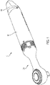
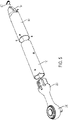
- Figs. 1-4 illustrate a non-limiting, exemplary embodiment of a ratcheting wrench 10 according to the present application.
- Fig. 1 is a top perspective view of the wrench 10
- Fig. 2 is a bottom perspective view of the wrench 10
- Fig. 3 is a side view of the wrench 10
- Fig. 4 is a top view of the wrench.
- the wrench 10 has a generally cylindrical body portion 100 and a tool head portion 200.
- the body portion 100 includes a handle 101 which can be gripped by a user.
- a rear end of the body portion 100 comprises a cap 105.
- a close-up view of the cap 105 is illustrated in Fig. 17 .
- the cap 105 may house a charging connector 110 such as the USB-C plug 110 shown in the exemplary embodiment. Other charging connectors may be used such as other types of USB plugs or other types of charging connectors.
- the cap 105 may also include air exhaust vents 106. Additionally, there may be a dust cap 107 preventing dust, debris or other materials from getting into the charging connector 110.
- the tool head portion 200 includes a tool head structure 201 and an output member 210.
- the output member 210 in this case is a ratcheting wrench output.
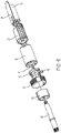
- Fig. 5 is an exploded view of the wrench 10 structural components.
- the wrench 10 includes a cap 105 at a rear end.
- the cap 105 is attached to a handle 101.
- the handle 101 is a cylindrically hollow tube.
- the handle 101 is integrally formed as a single part tube.
- a handle may be made differently, such as a pair of half-cylinders fastened together.
- the handle 101 is made of a semi-rigid plastic and the cap 105 is made of a hard plastic such that the cap 105 is made of a harder and more rigid material than the handle 101.
- the handle 101 and cap 105 may be made of the same material.
- the handle 101 and cap 105 may both be made of semi-rigid plastics or both may be made of hard plastics.
- Other exemplary embodiments may use other materials for the handle 101 and cap 105.
- a support tube 120 is disposed inside the handle 101.
- the support tube 120 is a cylindrically hollow tube.
- the support tube 120 is integrally formed as a single part tube. By using an integral part, rather than multiple half-tube components held together by fasteners, the rigidity of the tool can be increased.
- the rigidity of the wrench 10 of the present exemplary embodiment allows for manual usage that requires the tool to withstand high manual torques.
- a support tube may be made differently, such as a pair of half-cylinders fastened together.
- the support tube 120 provides structural support and rigidity to the wrench 10. This allows the wrench 10 to provide significant torque to a bolt without overly bending or breaking the body portion 100 of the wrench.
- the support tube 120 may be made of metal, such as phosphated steel. Phosphated steel provides good structural support and lightweight. Other metals or materials may be used.
- a front end of the wrench 10 includes a tool head portion 200.
- the tool head portion 200 includes the tool head structure 201 and output member 210.
- the tool head structure 201 is attached to both the support tube 120 and the handle 101.
- the tool head structure 201 may be made of metal such as steel or aluminum.
- Fig. 6 is an exploded view of mostly internal functional parts of the wrench 10. As shown in fig. 6 , the rear end of the assembly includes a battery cell 20.
- the battery cell 20 of the exemplary embodiment is a cylindrical battery cell.
- a printed circuit board (PCB) 25 is disposed on the battery cell 20.
- the PCB 25 is electrically connected to the positive and negative terminals of the battery cell 20.
- the USB connector 110 may be mounted on or to the PCB 25.
- the PCB 25 may also include a controller for functions related to control of the battery and the motor 40, such as a charge and discharge control for the battery 20.
- the battery cell 20 and PCB 25 are housed in skeleton 30 and together the battery cell 20, PCB 25 and skeleton 30 constitute a battery cell assembly.
- the skeleton 30 includes a number of fins 31 which may help direct airflow and dissipate heat.
- the skeleton 30 is housed inside the support tube 120 and portions of the skeleton 30 may contact an inner surface of the tube 120.
- the skeleton 30 of the exemplary embodiment is made of plastic. Using a material such as plastic with relatively low thermal and electrical connectivity may allow for protection of the PCB and other electrical components housed by the skeleton. Other materials having relatively low thermal and electrical connectivity may also be used.
- the skeleton 30 may help increase the rigidity of the support tube 120 and the wrench 10 overall.
- the motor 40 may be a brushed or brushless motor. Power is supplied to the motor 40 by the battery 20.
- the motor 40 includes a drive shaft 41.
- the motor 40 is also housed in the support tube 120 and an outer surface of the motor 40 may be in contact with an inner surface of the support tube 120 and help to provide rigidity to the support tube 120 and the wrench 10 overall.
- the wrench 10 includes an on/off crown 60.
- the crown 60 is slidable a small distance along a longitudinal axis of the wrench 10. Sliding the crown 60 rearward, causes the crown to activate switch 65 and activate the wrench 10.
- the crown 60 is connected to the PCB 25 by a wire or wires 66. This wire connection is shown in Figs. 7-12 .
- the crown 60 of the exemplary embodiment includes a projection 61 as shown in Fig. 11 . The projection 61 may contact the switch 65 to activate the switch 65.
- the crown 60 may be biased forward by a spring or other biasing member. In this forward position 60, the projection 61 is out of contact with the switch 65 and the wrench 10 is off. A user may then pull back the crown 60 so that the projection 61 actuates the switch 65.
- the wrench 10 is controlled so that power is provided by the battery 20 to the motor 40.
- Rotary motion of the motor output shaft 41 is transferred to shaft 55 through a reduction gearbox 50.
- the transmission shaft 55 transmits this power to the output 210 in order to drive the output member 210 and tighten or loosen bolts or perform other work.
- the wrench 10 is configured to provide significant power and torque while maintaining a compact shape. Additionally, the wrench is configured to have sufficient stiffness that it can be used manually as well as through motor power.
- the motor 40 used for the wrench 10 is an outer rotor, brushless DC motor 40. This provides high torque while maintaining a small footprint.
- the motor 40 has an outer diameter of 30 millimeters (mm).
- the motor 40 may have an outer diameter of 45 mm or less; 40 mm or less; 35 mm or less; or 30 mm or less.
- the battery cell 20 is a 21700 battery cell having a diameter of 21 mm and a length of 700 mm.
- the maximum initial battery voltage (measured without a workload) is 4 volts.
- the nominal voltage is 3.6V.
- the wrench 10 has a longitudinal axis X and a body diameter A.
- the diameter A of the body is an outer diameter of the handle 101.
- the diameter A of the exemplary embodiment may be about 40 mm. This is only about 33% larger than the diameter of the motor 40 of the exemplary embodiment.
- the diameter A may be 50 mm or less; 45 mm or less; or 40 mm or less.
- the diameter A of the body may be no more than 35% larger than the diameter of the motor; no more than 40% larger than the diameter of the motor; or no more than 45% larger than the diameter of the motor.
- Figs. 7-14 illustrate an assembly of the parts of the wrench 10.
- the figures are arranged in order of assembly such that Fig. 7 is the earliest step of assembly and Fig. 14 is the latest step.
- Figs. 7-14 illustrate a non-limiting, exemplary embodiment of an order of assembly operation and assembly may be performed in a different order in different embodiments.
- the motor 40 and battery cell 20 is provided.
- the PCB 25 is attached to the battery cell 20.
- the switch 65 is connected to the PCB 25 through a wire 66.
- the PCB 25 may be fixed to the battery cell 20 by soldering and adhesive or other means or may be disposed adjacent to the battery cell 20 and located by is placement in the skeleton 30.
- the alignment flange 45 is secured to the motor 40.
- the alignment flange 45 is secured to the motor 40 by screws 47. Other methods for attaching the alignment flange 45 may also be used.
- the battery cell 20 and PCB 25 are engaged with a skeleton 30.
- the skeleton 30 may also include the clips 32 for attaching to the motor 40.
- the clips 32 are designed to securely engage with a rear protrusion 42 on the motor.
- the skeleton 30 may include pathways or grips for wires or other electrical connectors to provide an electrical connection between the battery cell 20 and the PCB 25.
- Fig. 8 also illustrates a spring 67 that biases the crown 60 forward away from engaging the switch 65.
- the spring 67 may be attached to the flange 45 in the step illustrated in Fig. 8 .
- the skeleton 30 is attached to the motor 40 via the clips 32.
- the clips 32 attach around a rear protrusion 42 of the motor 40.
- the switch 65 is attached to the alignment flange 45 by glue.
- Fig. 10 illustrates the reduction gearbox 50 and shaft 55 being attached to the alignment flange 45.
- the shaft 55 is aligned with the output shaft 41 and is driven by the motor 40 through the output shaft 41.
- the shaft 55 is attached to the reduction gearbox 50 before the gearbox 50 is attached to the motor 40.
- the reduction gearbox 50 may be attached to the motor 40 before the shaft 55 is attached to the gearbox.
- the crown 60 and the tool head portion 210 are added.
- the crown 60 includes a projection 61 which actuates the switch 65.
- the tool head portion 210 is attached to the alignment flange 45 by clips.
- the support tube 120 is then attached and assembled from the rear side of the assembly of the wrench 10. As shown in Fig. 13 , the support tube 120 is secured in place by fasteners such as screws 121 (shown in Fig. 14 ). Then the handle 101 and the cap 105 are assembled over the support tube 120.
- the handle 101 may be secured by a snap-fit, clips adhesives or additional fasteners.
- the support tube 120 may be assembled, the handle 101 may be assembled over the support tube 120 and the same fastener or fasteners may be inserted through both the handle 101 and the support tube 120 in order to secure both the handle 101 and the support tube 120.
- the screws 121 may not be used until both the support tube 120 and handle 101 are assemble and then the screws 121 may extend through both the support tube 120 and handle 101 so as to secure both the support tube 120 and handle.
- the cap 105 is assembled to the handle 101 and then the handle 101 and cap 105 are together slid over the support tube 120 to assemble the parts.
- the cap 105 may be assembled to the handle 101 after the handle 101 is slid over the support tube 120.
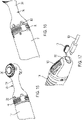
- Figs. 15 and 16 are close-up views of a portion of the wrench 10 including the crown 60.
- Fig. 15 illustrates the crown 60 in the off position.
- the crown 60 is moved to the forward position by the spring 67 so that the crown 60 is out of contact with the switch 65. This forward position is relatively closer to the output member 210.
- Fig. 16 illustrates the crown 60 in the on/activate/actuation position.
- the crown 60 is moved rearward, away from the output member 210.
- the projection 61 (see Fig. 11 ) of the crown 60 contacts the switch 65 to turn on the wrench 10.
- the user may move the crown 60 rearwardly against the biasing force of the spring 67.
- the length of travel of the crown 60 in the exemplary embodiment of the wrench 10 is small.
- the axial length of travel of the crown 60 from the forward/off position to the rearward/on position may be 100 mm or less; 80 mm or less. or 60 mm or less.
- the small axial travel may allow for easy operation of the crown. In other embodiments, the axial length of travel may be more or less.
- the placement of the crown forward of the motor 40 and adjacent to the handle 101 provides for convenient actuation.
- a user may generally grip the handle 101 and use a forward finger or fingers to pull back the crown 60 and actuate the wrench.
- the tool head structure 201 includes air intakes 202. Air may enter the air intakes 202 flow around the motor 40 and skeleton 30 and exit in air exhaust 106 shown in Fig. 17 .
- Fig. 17 is a close-up perspective view of a rear end of the wrench 10 including the cap 105.
- the cap 105 includes a charging connector 110 which can receive a charging cord connector 500.
- the charging connector 110 is a USB-C connector.
- the cap 105 also include the air exhaust vents 106.
- the air exhaust vents 106 are a series of parallel openings in the cap 105.
- the tool head portion 200 includes intakes 202 and the cap 105 includes air exhaust vents 106.
- the motor 40 may include a fan which drives airflow in this direction such that air generally flows in through the intakes 202 and out through the exhaust vents 106.
- a fan may drive airflow in the opposite direction such that the vents 106 in the cap 105 generally receive air and the vents 202 in the tool head structure 201 generally exhaust the air.
- the airflow may be ambient airflow. In that case, airflow may not be primarily in one direction, but may change depending upon the orientation of the wrench 10 or other factors such as heat dispersion.
- the wrench 10 is powered by an internal battery cell 20.
- the battery cell 20 may be configured to be removable or the wrench 10 may be powered by a battery pack that is removable.
- other embodiments may include more than one battery cell 20. For example, two battery cells may be placed end to end. The multiple battery cells may be accommodated by extending a length of the tool, such as the length of the handle 101.
- FIG. 18-20 Another exemplary embodiment of a wrench 410 is shown in Figs. 18-20 .
- the wrench 410 is the same as the wrench 10 unless otherwise shown or noted.
- the wrench 410 is similar to the wrench 10, except near the forward end of the wrench 410.
- the wrench 410 has a forward portion 500 made up of a tool head 505 and a connector 520.
- the tool head 505 includes an output member 510, similar to the output member 210.
- the output member 510 is a ratcheting wrench output member.
- Other exemplary embodiments may include other output members such as a screwdriver or rotary tool output member.
- the tool head 505 is shown with the connector 520 in Fig. 19 and the tool head 505 is shown with the connector 520 in Fig. 20 .
- Fig. 21 is a perspective view of the wrench 410 with the handle 101 removed.
- the wrench 410 includes a modified actuation system as compared to the previous embodiment wrench 10.
- Fig. 22 illustrates a close-up view of various parts of the actuation system of wrench 410.
- the wrench 410 includes an on/off crown 60 like the wrench 10.
- the crown 60 allows a user to actuate the wrench from a variety of positions by pulling the crown 60 rearward.
- the crown 60 includes a projection 62.
- the projection 62 connects to a rod 71 so that moving the crown 60 rearward, moves the projection 62 rearward and in turn the rod 71 is moved rearward.
- the rod 71 is housed in a tube 70 that runs along the support tube 120.
- the rod 71 and tube 70 may both be made of stainless steel. Other non-magnetic materials may be used instead of stainless steel, and other shapes of actuating mechanism or actuating member (e.g. another elongate actuating member), other than a rod, may be employed.
- the rod 71 At a rear end of the rod 71 there is a magnet 72.
- the rod 71 may be biased forward by a spring 74 that is held in place by a cap 73 at the end of the tube 70.
- the wrench 410 also includes a hall effect sensor 75 which detects the magnet 72.
- the user may pull back the crown 60 to actuate the wrench.
- the projection 62 pushes back the rod 71 against the biasing force of the spring 74.
- the magnet 72 at the end of the rod 71 is pushed to a position to be detected by the hall sensor 75.
- the hall effect sensor 75 is operatively connected to the printed circuit board 25.
- a controller may be mounted on the PCB 25. When the movement of the magnet 72 is detected, the motor is turned on to operate the wrench 410.
- the rod 71 serves as a linkage so that while the crown 60 is near a front of the wrench 410 at a location easily actuatable by the user, it provides an actuation signal with a magnet 72 and hall effect sensor 75 near a rear of the wrench 410.
- a hall effect sensor 75 and magnet 72 combination is used in the exemplary embodiment of the wrench 410, a mechanical switch system may also be used. In that instance, the rod or a similar linkage may cause the depression of a microswitch which is connected to the PCB 25. If a mechanical switch is used, different materials may be used for the rod and the tube.
- the rod 71 and tube 70 are on a side of the support tube 120 opposite to the PCB 25.
- the rod 71 and tube 70 or another linkage system may run adjacent to the support tube 120 at the side adjacent to the PCB 25.
- Fig. 23 is a cross sectional view of the wrench 410 at the crown 60.
- the crown 60 may be biased by a compression spring 77 that wraps around circumference of the support tube 120 and is enclosed between the support tube 120 and the crown 60. Because the spring 77 wraps around the circumference, it provides a symmetrical biasing force.
- the spring 77 is held at a front end by a shoulder 78 of the crown and at a rear end by a blocking shoulder 79.
- the present disclosure contemplates that, to the extent possible, one or more features of any embodiment can be combined or exchanged with one or more features of any other embodiment.
- the compression spring 77 may be used with the exemplary embodiment of the wrench 10 instead of or in addition to the spring 67.
- the actuation system utilizing the projection 62, tube 70, rod 71, magnet 72 and hall sensor 75 may be used in the exemplary embodiment of the wrench 10 in place of the projection 61 and switch 65.
Landscapes
- Engineering & Computer Science (AREA)
- Mechanical Engineering (AREA)
- Life Sciences & Earth Sciences (AREA)
- Biophysics (AREA)
- Computer Hardware Design (AREA)
- Chemical & Material Sciences (AREA)
- Chemical Kinetics & Catalysis (AREA)
- Electrochemistry (AREA)
- General Chemical & Material Sciences (AREA)
- Details Of Spanners, Wrenches, And Screw Drivers And Accessories (AREA)
Abstract
A wrench includes a tool head including a tool output member. The wrench also includes a motor configured to selectively drive the output member and a battery assembly. The battery assembly includes a battery cell which is configured to provide electrical power to the motor. A support tube surrounds and supports at least a portion of the motor and at least a portion of the battery assembly. A handle surrounds, and is supported by, the support tube. The support tube and the handle are elongate and substantially coaxial with each other and with a longitudinal axis of the wrench, and the motor and the battery assembly are arranged longitudinally adjacent to each other.
Description
- The present invention relates to electrically-powered wrenches.
- There are various existing powered wrenches. It is desired to provide a powered wrench with an improved construction.
- According to a first aspect, the invention provides a wrench according to
Claim 1 of the appended claims. - Preferred, and other optional, features of the invention are defined and described in the dependent claims.
- According to another aspect, there is an exemplary embodiment of a wrench. The wrench includes a motor; a battery assembly including a battery cell; a support tube surrounding at least a portion of the motor and a portion of the battery assembly; and a handle surrounding the support tube.
- The support tube may surround at least a portion of the battery cell.
- The battery assembly may include a printed circuit board.
- The battery assembly may include a skeleton.
- The printed circuit board and the battery cell may be housed in the skeleton.
- The skeleton may include fins.
- The support tube may be hollow and cylindrical.
- The support tube may be made of steel.
- The support tube may be made of phosphate steel.
- The support tube may be an integrally formed tube.
- The handle may be an integrally formed tube.
- The handle may be made of plastic.
- The handle may be made of semi-rigid plastic.
- The wrench may further include an end cap secured to a rear end of the handle.
- The end cap may be made of a hard plastic.
- The wrench may have a forward end with an output member and a rear end opposite the forward end.
- The motor may have a motor forward end closer to the forward end of the wrench and a motor rear end opposite the motor forward end.
- The wrench may further include an actuating switch near the motor forward end.
- The wrench may further include a wire connecting the switch to the printed circuit board.
- The wrench may further include a crown configured to actuate the wrench.
- The crown may be configured to translate.
- The crown may be biased toward a forward end of the wrench.
- The crown may be biased into the off position.
- According to another aspect, there is an exemplary method of assembly of a wrench. The method may include: providing a motor and a battery assembly; connecting the motor and the battery assembly; connecting a tool head to the motor; and sliding a support tube over at least a portion of the motor and the battery assembly.
- The support tube may be a hollow cylindrical tube.
- The battery assembly may include a battery cell.
- The support tube may be slid over at least a portion of the battery cell.
- The support tube may be an integral single part.
- The method may further include sliding a handle over the support tube.
- The handle may be a hollow tube.
- The handle may be an integral single part.
- The method may further include assembling an end cap to the handle.
- The end cap may be assembled with the handle before the handle is slid over the support tube.
- In another aspect, there is an exemplary embodiment of a wrench. The wrench includes a motor; a battery assembly including a battery cell; a support tube surrounding at least a portion of the motor and a portion of the battery assembly; and a handle surrounding the support tube. A user-actuated crown is located near a forward end of the wrench for actuation of the wrench.
- The wrench may further include a rod operatively connected to the crown.
- The rod may be operatively connected to the crown by a projection.
- The rod may run along an outside of the support tube.
- The rod may be housed in a non-magnetic stainless steel housing tube.
- The rod may be non-magnetic.
- The rod may be stainless steel.
- A magnet may be affixed to an end of the rod opposite the crown.
- A rear end of the housing tube may be closed by a cap.
- A spring may be housed in the housing tube and bias the rod in a forward direction.
- The wrench may further comprise a hall effect sensor to sense the magnet.
- The wrench may be activated based on the hall effect sensor sensing the magnet.
- The printed circuit board may include a controller.
- In another aspect, a wrench is provided, comprising: a tool head including a tool output member; a motor configured to selectively drive the output member; a battery assembly including a battery cell, the battery cell providing power to the motor; a support tube surrounding at least a portion of the motor and a portion of the battery cell; a handle surrounding the support tube.
- The support tube may be an integrally formed tube.
- The battery assembly may include a printed circuit board and a skeleton.
- The skeleton may hold the printed circuit board and the battery cell.
- The handle may be an integrally formed tube.
- It is to be understood that any feature, including any preferred or otherwise optional feature, of any aspect or embodiment of the invention or disclosure, may be a feature, including a preferred or otherwise optional feature, of any other aspect or embodiment of the invention or disclosure.
- Embodiments of the invention will now be described, by way of example, with reference to the accompanying drawings, of which:
-
Fig. 1 illustrates a perspective view of an exemplary embodiment of a wrench according to the present application; -
Fig. 2 is another perspective view of the exemplary embodiment of a wrench; -
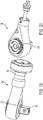
Fig. 3 is a side view of the exemplary embodiment of a wrench; -
Fig. 4 is a top view of the exemplary embodiment of a wrench; -
Fig. 5 is an exploded perspective view of the exemplary embodiment of a wrench; -
Fig. 6 is an exploded perspective view of the exemplary embodiment of a wrench; -
Fig. 7 is a side view of a partial assembly of the exemplary embodiment of a wrench; -
Fig. 8 is a side view of a partial assembly of the exemplary embodiment of a wrench; -
Fig. 9 is a side view of a partial assembly of the exemplary embodiment of a wrench; -
Fig. 10 is a side view of a partial assembly of the exemplary embodiment of a wrench; -
Fig. 11 is a side view of a partial assembly of the exemplary embodiment of a wrench; -
Fig. 12 is a side view of a partial assembly of the exemplary embodiment of a wrench; -
Fig. 13 is a side view of a partial assembly of the exemplary embodiment of a wrench; -
Fig. 14 is a side view of a partial assembly of the exemplary embodiment of a wrench; -
Fig. 15 is a close-up perspective view of a portion of the exemplary embodiment of a wrench; -
Fig. 16 is another close-up perspective view of a portion of the exemplary embodiment of a wrench; -
Fig. 17 is a close-up perspective view of a rear portion of the exemplary embodiment of a wrench; -
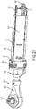
Fig. 18 is a perspective side view of a second exemplary embodiment of a wrench; -
Fig. 19 is a perspective side view of a portion of the second exemplary embodiment of the wrench; -
Fig. 20 is a perspective side view of a portion of the second exemplary embodiment of the wrench; -
Fig. 21 is a perspective view of the second exemplary embodiment of the wrench with selected parts removed; -
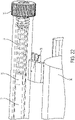
Figs. 22 is a close-up perspective view of selected parts of the second exemplary embodiment of the wrench; and -
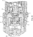
Fig. 23 is a cross-sectional side view of a portion of the second exemplary embodiment of the wrench. -
Figs. 1-4 illustrate a non-limiting, exemplary embodiment of a ratchetingwrench 10 according to the present application.Fig. 1 is a top perspective view of thewrench 10,Fig. 2 is a bottom perspective view of thewrench 10,Fig. 3 is a side view of thewrench 10 andFig. 4 is a top view of the wrench. As shown infigs. 1-4 , thewrench 10 has a generally cylindrical body portion 100 and atool head portion 200. The body portion 100 includes ahandle 101 which can be gripped by a user. - A rear end of the body portion 100 comprises a
cap 105. A close-up view of thecap 105 is illustrated inFig. 17 . Thecap 105 may house a chargingconnector 110 such as the USB-C plug 110 shown in the exemplary embodiment. Other charging connectors may be used such as other types of USB plugs or other types of charging connectors. Thecap 105 may also include air exhaust vents 106. Additionally, there may be adust cap 107 preventing dust, debris or other materials from getting into the chargingconnector 110. - The
tool head portion 200 includes atool head structure 201 and anoutput member 210. Theoutput member 210 in this case is a ratcheting wrench output. -
Fig. 5 is an exploded view of thewrench 10 structural components. As shown inFig. 5 , thewrench 10 includes acap 105 at a rear end. Thecap 105 is attached to ahandle 101. Thehandle 101 is a cylindrically hollow tube. In the exemplary embodiment, thehandle 101 is integrally formed as a single part tube. By using an integral part, rather than a handle made of multiple half-cylinder components held together by fasteners, the rigidity of the tool can be increased. - In other embodiments, a handle may be made differently, such as a pair of half-cylinders fastened together.
- In the exemplary embodiment, the
handle 101 is made of a semi-rigid plastic and thecap 105 is made of a hard plastic such that thecap 105 is made of a harder and more rigid material than thehandle 101. In other embodiments, thehandle 101 andcap 105 may be made of the same material. For example, thehandle 101 andcap 105 may both be made of semi-rigid plastics or both may be made of hard plastics. Other exemplary embodiments may use other materials for thehandle 101 andcap 105. - A
support tube 120 is disposed inside thehandle 101. Thesupport tube 120 is a cylindrically hollow tube. In the exemplary embodiment, thesupport tube 120 is integrally formed as a single part tube. By using an integral part, rather than multiple half-tube components held together by fasteners, the rigidity of the tool can be increased. The rigidity of thewrench 10 of the present exemplary embodiment allows for manual usage that requires the tool to withstand high manual torques. - In other embodiments, a support tube may be made differently, such as a pair of half-cylinders fastened together.
- The
support tube 120 provides structural support and rigidity to thewrench 10. This allows thewrench 10 to provide significant torque to a bolt without overly bending or breaking the body portion 100 of the wrench. Thesupport tube 120 may be made of metal, such as phosphated steel. Phosphated steel provides good structural support and lightweight. Other metals or materials may be used. - A front end of the
wrench 10 includes atool head portion 200. Thetool head portion 200 includes thetool head structure 201 andoutput member 210. Thetool head structure 201 is attached to both thesupport tube 120 and thehandle 101. Thetool head structure 201 may be made of metal such as steel or aluminum. -
Fig. 6 is an exploded view of mostly internal functional parts of thewrench 10. As shown infig. 6 , the rear end of the assembly includes abattery cell 20. Thebattery cell 20 of the exemplary embodiment is a cylindrical battery cell. A printed circuit board (PCB) 25 is disposed on thebattery cell 20. ThePCB 25 is electrically connected to the positive and negative terminals of thebattery cell 20. Additionally, theUSB connector 110 may be mounted on or to thePCB 25. ThePCB 25 may also include a controller for functions related to control of the battery and themotor 40, such as a charge and discharge control for thebattery 20. - The
battery cell 20 andPCB 25 are housed inskeleton 30 and together thebattery cell 20,PCB 25 andskeleton 30 constitute a battery cell assembly. In the exemplary embodiment, theskeleton 30 includes a number offins 31 which may help direct airflow and dissipate heat. Theskeleton 30 is housed inside thesupport tube 120 and portions of theskeleton 30 may contact an inner surface of thetube 120. Theskeleton 30 of the exemplary embodiment is made of plastic. Using a material such as plastic with relatively low thermal and electrical connectivity may allow for protection of the PCB and other electrical components housed by the skeleton. Other materials having relatively low thermal and electrical connectivity may also be used. - In some exemplary embodiments, the
skeleton 30 may help increase the rigidity of thesupport tube 120 and thewrench 10 overall. - A front end of the
skeleton 30 engages a rear of themotor 40. Themotor 40 may be a brushed or brushless motor. Power is supplied to themotor 40 by thebattery 20. Themotor 40 includes adrive shaft 41. Themotor 40 is also housed in thesupport tube 120 and an outer surface of themotor 40 may be in contact with an inner surface of thesupport tube 120 and help to provide rigidity to thesupport tube 120 and thewrench 10 overall. - An
alignment flange 45 is attached to a front end of themotor 40. Thealignment flange 45 helps to align themotor 40 with areduction gearbox 50. Atransmission shaft 55 is connected to theoutput member 210. As also shown inFig. 6 , thewrench 10 includes an on/offcrown 60. Thecrown 60 is slidable a small distance along a longitudinal axis of thewrench 10. Sliding thecrown 60 rearward, causes the crown to activateswitch 65 and activate thewrench 10. Thecrown 60 is connected to thePCB 25 by a wire orwires 66. This wire connection is shown inFigs. 7-12 . Thecrown 60 of the exemplary embodiment includes aprojection 61 as shown inFig. 11 . Theprojection 61 may contact theswitch 65 to activate theswitch 65. - The
crown 60 may be biased forward by a spring or other biasing member. In thisforward position 60, theprojection 61 is out of contact with theswitch 65 and thewrench 10 is off. A user may then pull back thecrown 60 so that theprojection 61 actuates theswitch 65. When theswitch 65 is activated, thewrench 10 is controlled so that power is provided by thebattery 20 to themotor 40. Rotary motion of themotor output shaft 41 is transferred toshaft 55 through areduction gearbox 50. Thetransmission shaft 55 transmits this power to theoutput 210 in order to drive theoutput member 210 and tighten or loosen bolts or perform other work. - The
wrench 10 is configured to provide significant power and torque while maintaining a compact shape. Additionally, the wrench is configured to have sufficient stiffness that it can be used manually as well as through motor power. - The
motor 40 used for thewrench 10 is an outer rotor,brushless DC motor 40. This provides high torque while maintaining a small footprint. In the exemplary embodiment, themotor 40 has an outer diameter of 30 millimeters (mm). In various embodiments, themotor 40 may have an outer diameter of 45 mm or less; 40 mm or less; 35 mm or less; or 30 mm or less. - The
battery cell 20 is a 21700 battery cell having a diameter of 21 mm and a length of 700 mm. The maximum initial battery voltage (measured without a workload) is 4 volts. The nominal voltage is 3.6V. - As shown in
Fig. 3 , thewrench 10 has a longitudinal axis X and a body diameter A. In this case, the diameter A of the body is an outer diameter of thehandle 101. Owing to the compact nature of the design of the exemplary embodiment, the diameter A of the exemplary embodiment may be about 40 mm. This is only about 33% larger than the diameter of themotor 40 of the exemplary embodiment. In various embodiments, the diameter A may be 50 mm or less; 45 mm or less; or 40 mm or less. Additionally, the diameter A of the body may be no more than 35% larger than the diameter of the motor; no more than 40% larger than the diameter of the motor; or no more than 45% larger than the diameter of the motor. -
Figs. 7-14 illustrate an assembly of the parts of thewrench 10. The figures are arranged in order of assembly such thatFig. 7 is the earliest step of assembly andFig. 14 is the latest step.Figs. 7-14 illustrate a non-limiting, exemplary embodiment of an order of assembly operation and assembly may be performed in a different order in different embodiments. - As shown in
Fig. 7 , themotor 40 andbattery cell 20 is provided. ThePCB 25 is attached to thebattery cell 20. Additionally, theswitch 65 is connected to thePCB 25 through awire 66. ThePCB 25 may be fixed to thebattery cell 20 by soldering and adhesive or other means or may be disposed adjacent to thebattery cell 20 and located by is placement in theskeleton 30. - As shown in
Fig. 8 , thealignment flange 45 is secured to themotor 40. In the exemplary embodiment, thealignment flange 45 is secured to themotor 40 by screws 47. Other methods for attaching thealignment flange 45 may also be used. As additionally shown inFig. 8 , thebattery cell 20 andPCB 25 are engaged with askeleton 30. Theskeleton 30 may also include the clips 32 for attaching to themotor 40. The clips 32 are designed to securely engage with arear protrusion 42 on the motor. Theskeleton 30 may include pathways or grips for wires or other electrical connectors to provide an electrical connection between thebattery cell 20 and thePCB 25. -
Fig. 8 also illustrates aspring 67 that biases thecrown 60 forward away from engaging theswitch 65. Thespring 67 may be attached to theflange 45 in the step illustrated inFig. 8 . - In
Fig. 9 , theskeleton 30 is attached to themotor 40 via the clips 32. In particular, the clips 32 attach around arear protrusion 42 of themotor 40. Additionally, theswitch 65 is attached to thealignment flange 45 by glue. -
Fig. 10 illustrates thereduction gearbox 50 andshaft 55 being attached to thealignment flange 45. Theshaft 55 is aligned with theoutput shaft 41 and is driven by themotor 40 through theoutput shaft 41. InFig. 10 , theshaft 55 is attached to thereduction gearbox 50 before thegearbox 50 is attached to themotor 40. In an alternative embodiment, thereduction gearbox 50 may be attached to themotor 40 before theshaft 55 is attached to the gearbox. - In the assembly steps shown in
Figs. 11 and 12 , thecrown 60 and thetool head portion 210 are added. As shown inFig. 11 , thecrown 60 includes aprojection 61 which actuates theswitch 65. Thetool head portion 210 is attached to thealignment flange 45 by clips. - As shown in
Fig. 13 , thesupport tube 120 is then attached and assembled from the rear side of the assembly of thewrench 10. As shown inFig. 13 , thesupport tube 120 is secured in place by fasteners such as screws 121 (shown inFig. 14 ). Then thehandle 101 and thecap 105 are assembled over thesupport tube 120. Thehandle 101 may be secured by a snap-fit, clips adhesives or additional fasteners. In alternative embodiments, thesupport tube 120 may be assembled, thehandle 101 may be assembled over thesupport tube 120 and the same fastener or fasteners may be inserted through both thehandle 101 and thesupport tube 120 in order to secure both thehandle 101 and thesupport tube 120. For example, thescrews 121 may not be used until both thesupport tube 120 and handle 101 are assemble and then thescrews 121 may extend through both thesupport tube 120 and handle 101 so as to secure both thesupport tube 120 and handle. - In
Fig. 14 thecap 105 is assembled to thehandle 101 and then thehandle 101 andcap 105 are together slid over thesupport tube 120 to assemble the parts. In another exemplary embodiment, thecap 105 may be assembled to thehandle 101 after thehandle 101 is slid over thesupport tube 120. -
Figs. 15 and 16 are close-up views of a portion of thewrench 10 including thecrown 60.Fig. 15 illustrates thecrown 60 in the off position. InFig. 15 thecrown 60 is moved to the forward position by thespring 67 so that thecrown 60 is out of contact with theswitch 65. This forward position is relatively closer to theoutput member 210. -
Fig. 16 illustrates thecrown 60 in the on/activate/actuation position. InFig. 16 thecrown 60 is moved rearward, away from theoutput member 210. In this rearward position, the projection 61 (seeFig. 11 ) of thecrown 60 contacts theswitch 65 to turn on thewrench 10. The user may move thecrown 60 rearwardly against the biasing force of thespring 67. The length of travel of thecrown 60 in the exemplary embodiment of thewrench 10 is small. The axial length of travel of thecrown 60 from the forward/off position to the rearward/on position may be 100 mm or less; 80 mm or less. or 60 mm or less. The small axial travel may allow for easy operation of the crown. In other embodiments, the axial length of travel may be more or less. - The placement of the crown forward of the
motor 40 and adjacent to thehandle 101 provides for convenient actuation. A user may generally grip thehandle 101 and use a forward finger or fingers to pull back thecrown 60 and actuate the wrench. - As further shown in
Figs. 15 and 16 , thetool head structure 201 includesair intakes 202. Air may enter the air intakes 202 flow around themotor 40 andskeleton 30 and exit inair exhaust 106 shown inFig. 17 . -
Fig. 17 is a close-up perspective view of a rear end of thewrench 10 including thecap 105. As shown inFig. 17 , thecap 105 includes a chargingconnector 110 which can receive acharging cord connector 500. In the exemplary embodiment, the chargingconnector 110 is a USB-C connector. Thecap 105 also include the air exhaust vents 106. The air exhaust vents 106 are a series of parallel openings in thecap 105. - In the exemplary embodiment, the
tool head portion 200 includesintakes 202 and thecap 105 includes air exhaust vents 106. Themotor 40 may include a fan which drives airflow in this direction such that air generally flows in through theintakes 202 and out through the exhaust vents 106. In other embodiments, a fan may drive airflow in the opposite direction such that thevents 106 in thecap 105 generally receive air and thevents 202 in thetool head structure 201 generally exhaust the air. In other embodiments, the airflow may be ambient airflow. In that case, airflow may not be primarily in one direction, but may change depending upon the orientation of thewrench 10 or other factors such as heat dispersion. - In the exemplary embodiment, the
wrench 10 is powered by aninternal battery cell 20. In other embodiments, thebattery cell 20 may be configured to be removable or thewrench 10 may be powered by a battery pack that is removable. Additionally, other embodiments may include more than onebattery cell 20. For example, two battery cells may be placed end to end. The multiple battery cells may be accommodated by extending a length of the tool, such as the length of thehandle 101. - Another exemplary embodiment of a
wrench 410 is shown inFigs. 18-20 . Thewrench 410 is the same as thewrench 10 unless otherwise shown or noted. In particular, thewrench 410 is similar to thewrench 10, except near the forward end of thewrench 410. Thewrench 410 has aforward portion 500 made up of atool head 505 and aconnector 520. Thetool head 505 includes anoutput member 510, similar to theoutput member 210. In the exemplary embodiment, theoutput member 510 is a ratcheting wrench output member. Other exemplary embodiments may include other output members such as a screwdriver or rotary tool output member. - The
tool head 505 is shown with theconnector 520 inFig. 19 and thetool head 505 is shown with theconnector 520 inFig. 20 . -
Fig. 21 is a perspective view of thewrench 410 with thehandle 101 removed. Thewrench 410 includes a modified actuation system as compared to theprevious embodiment wrench 10.Fig. 22 illustrates a close-up view of various parts of the actuation system ofwrench 410. - The
wrench 410 includes an on/offcrown 60 like thewrench 10. Thecrown 60 allows a user to actuate the wrench from a variety of positions by pulling thecrown 60 rearward. In thewrench 410, thecrown 60 includes aprojection 62. Theprojection 62 connects to arod 71 so that moving thecrown 60 rearward, moves theprojection 62 rearward and in turn therod 71 is moved rearward. Therod 71 is housed in atube 70 that runs along thesupport tube 120. Therod 71 andtube 70 may both be made of stainless steel. Other non-magnetic materials may be used instead of stainless steel, and other shapes of actuating mechanism or actuating member (e.g. another elongate actuating member), other than a rod, may be employed. At a rear end of therod 71 there is amagnet 72. As best shown inFig. 22 , therod 71 may be biased forward by aspring 74 that is held in place by acap 73 at the end of thetube 70. As also shown inFig. 22 , thewrench 410 also includes ahall effect sensor 75 which detects themagnet 72. - According to the construction of the exemplary embodiment shown in
Figs. 21 and22 , the user may pull back thecrown 60 to actuate the wrench. When the user pulls back thecrown 60, theprojection 62 pushes back therod 71 against the biasing force of thespring 74. Themagnet 72 at the end of therod 71 is pushed to a position to be detected by thehall sensor 75. Thehall effect sensor 75 is operatively connected to the printedcircuit board 25. A controller may be mounted on thePCB 25. When the movement of themagnet 72 is detected, the motor is turned on to operate thewrench 410. - As will be appreciated, in the embodiment of the
wrench 410, therod 71 serves as a linkage so that while thecrown 60 is near a front of thewrench 410 at a location easily actuatable by the user, it provides an actuation signal with amagnet 72 andhall effect sensor 75 near a rear of thewrench 410. Although ahall effect sensor 75 andmagnet 72 combination is used in the exemplary embodiment of thewrench 410, a mechanical switch system may also be used. In that instance, the rod or a similar linkage may cause the depression of a microswitch which is connected to thePCB 25. If a mechanical switch is used, different materials may be used for the rod and the tube. - As shown in
Figs. 21 and22 , therod 71 andtube 70 are on a side of thesupport tube 120 opposite to thePCB 25. In other embodiment, therod 71 andtube 70 or another linkage system may run adjacent to thesupport tube 120 at the side adjacent to thePCB 25. -
Fig. 23 is a cross sectional view of thewrench 410 at thecrown 60. As shown inFig. 23 , thecrown 60 may be biased by acompression spring 77 that wraps around circumference of thesupport tube 120 and is enclosed between thesupport tube 120 and thecrown 60. Because thespring 77 wraps around the circumference, it provides a symmetrical biasing force. Thespring 77 is held at a front end by ashoulder 78 of the crown and at a rear end by a blockingshoulder 79. - Although the description provided above provides detail for the purpose of illustration based on what is currently considered to be the most practical and preferred embodiments, it is to be understood that such detail is solely for that purpose and that the disclosure is not limited to the expressly disclosed embodiments, but, on the contrary, is intended to cover modifications and equivalent arrangements that are within the scope of the appended claims.
- It is to be understood that the present disclosure contemplates that, to the extent possible, one or more features of any embodiment can be combined or exchanged with one or more features of any other embodiment. For example, the
compression spring 77 may be used with the exemplary embodiment of thewrench 10 instead of or in addition to thespring 67. Similarly, the actuation system utilizing theprojection 62,tube 70,rod 71,magnet 72 andhall sensor 75 may be used in the exemplary embodiment of thewrench 10 in place of theprojection 61 andswitch 65.
Claims (15)
- A wrench, comprising:a tool head including a tool output member;a motor configured to selectively drive the output member;a battery assembly including a battery cell, the battery cell configured to provide electrical power to the motor;a support tube surrounding and supporting at least a portion of the motor and at least a portion of the battery assembly; anda handle surrounding, and supported by, the support tube;wherein the support tube and the handle are elongate and substantially coaxial with each other and with a longitudinal axis (X) of the wrench, and the motor is situated longitudinally between the tool head and the battery assembly.
- The wrench of claim 1, wherein the support tube surrounds at least a portion of the battery cell.
- The wrench of claim 1 or claim 2, wherein the support tube is hollow and cylindrical.
- The wrench of any preceding claim, wherein the support tube is an integrally formed single-part tube.
- The wrench of any preceding claim, wherein the battery assembly includes a printed circuit board and a skeleton, and the skeleton holds the printed circuit board and the battery cell.
- The wrench of claim 5, further comprising a controller mounted to the printed circuit board.
- The wrench of any preceding claim, wherein the handle is substantially in the form of a tube, preferably an integrally formed single-part tube.
- The wrench of any preceding claim, wherein the handle is made of semi-rigid plastic.
- The wrench of any preceding claim, further comprising an end cap secured to a rear end of the handle.
- The wrench of claim 9, wherein the end cap is made of a substantially rigid plastic, preferably a hard plastic.
- The wrench of any preceding claim, further comprising a longitudinally-slidable crown collar configured to actuate the wrench by activating an actuating switch of the wrench, the crown collar configured to be longitudinally-slidable by a user of the wrench to activate the actuating switch, the crown collar preferably situated between the tool head and the handle, on the exterior of the wrench.
- The wrench of claim 11, wherein the wrench has a forward end with an output member and a rear end opposite the forward end;wherein the motor has a motor forward end closer to the forward end of the wrench and a motor rear end opposite the motor forward end; andwherein the crown collar is relatively near the forward end of the wrench, the actuating switch is relatively near the rear end of the wrench, and an actuation mechanism for activating the actuating switch extends between the crown collar and the actuating switch.
- The wrench of Claim 12, wherein the actuation mechanism comprises a rod or other elongate actuation member attached to the crown collar.
- The wrench of Claim 12 or Claim 13, wherein the switch is located substantially at the rear of the battery assembly.
- The wrench of any one of claims 12 to 14, wherein the actuation mechanism comprises a magnet and a Hall Effect sensor configured such that detection of the magnetic field of the magnet activates or deactivates the switch, or comprises activation or deactivation of the switch.
Applications Claiming Priority (1)
| Application Number | Priority Date | Filing Date | Title |
|---|---|---|---|
| US202163153758P | 2021-02-25 | 2021-02-25 |
Publications (1)
| Publication Number | Publication Date |
|---|---|
| EP4049793A1 true EP4049793A1 (en) | 2022-08-31 |
Family
ID=80449097
Family Applications (1)
| Application Number | Title | Priority Date | Filing Date |
|---|---|---|---|
| EP22158423.8A Withdrawn EP4049793A1 (en) | 2021-02-25 | 2022-02-24 | Powered wrench |
Country Status (2)
| Country | Link |
|---|---|
| US (2) | US12502760B2 (en) |
| EP (1) | EP4049793A1 (en) |
Cited By (2)
| Publication number | Priority date | Publication date | Assignee | Title |
|---|---|---|---|---|
| EP4257298A1 (en) * | 2022-03-08 | 2023-10-11 | Black & Decker, Inc. | Power tool |
| TWI898202B (en) * | 2023-04-12 | 2025-09-21 | 鑽全實業股份有限公司 | Compact powered ratcheting wrench |
Families Citing this family (4)
| Publication number | Priority date | Publication date | Assignee | Title |
|---|---|---|---|---|
| US20240157525A1 (en) * | 2022-11-11 | 2024-05-16 | Nanjing Chervon Industry Co., Ltd. | Impact tool |
| TWI877548B (en) * | 2022-12-15 | 2025-03-21 | 鑽全實業股份有限公司 | Powered wrench with built-in battery |
| TWM654251U (en) | 2023-04-12 | 2024-04-21 | 鑽全實業股份有限公司 | Electric ratchet wrench |
| JP7745031B2 (en) * | 2023-04-12 | 2025-09-26 | 鑽全實業股▲分▼有限公司 | Electric Ratchet Wrench |
Citations (5)
| Publication number | Priority date | Publication date | Assignee | Title |
|---|---|---|---|---|
| GB2415652A (en) * | 2004-06-29 | 2006-01-04 | Techway Ind Co Ltd | Cordless ratchet wrench |
| US20130161039A1 (en) * | 2011-06-27 | 2013-06-27 | Robert Bosch Gmbh | Handheld Power Tool, in particular a Power Drill or Screwdriver |
| WO2016008321A1 (en) * | 2014-07-17 | 2016-01-21 | 苏州斯坦科机电有限公司 | Manual-automatic integration screwdriver and accommodating base thereof, and charging loop |
| WO2018121723A1 (en) * | 2016-12-30 | 2018-07-05 | 博世电动工具(中国)有限公司 | Electric screwdriver |
| WO2019105097A1 (en) * | 2017-11-29 | 2019-06-06 | 苏州多维思智能科技有限公司 | Precise electric screwdriver |
Family Cites Families (97)
| Publication number | Priority date | Publication date | Assignee | Title |
|---|---|---|---|---|
| US4006334A (en) | 1975-03-17 | 1977-02-01 | Mcgraw-Edison Company | Safety switch for power tool |
| AT388530B (en) | 1987-04-24 | 1989-07-25 | Philips Nv | DRY SHAVER WITH A SLIDING SHUTTER |
| DE3718804A1 (en) | 1987-06-05 | 1988-12-15 | Gardner Denver Gmbh | SCREWDRIVER |
| DE3727921C1 (en) | 1987-08-21 | 1989-01-05 | Braun Ag | Switch for switching an electrically operable drive part of a device on and off |
| DE3729257A1 (en) | 1987-09-02 | 1989-03-23 | Braun Ag | DRY SHAVER WITH A SHORT HAIR CUTTING SYSTEM AND A SLIDING LONG HAIR CUTTING SYSTEM |
| US4910365A (en) | 1989-05-01 | 1990-03-20 | Stanley Kuo | Securable rocker switch used for personal protection devices |
| DE59008112D1 (en) | 1989-07-15 | 1995-02-09 | Kress Elektrik Gmbh & Co | Power tool. |
| EP0408986B1 (en) | 1989-07-15 | 1995-01-18 | Kress-elektrik GmbH + Co. Elektromotorenfabrik | Switch device for electrical change-over switching of electric tools |
| US4974475A (en) | 1989-07-19 | 1990-12-04 | Skil Corporation | Cordless powered ratchet wrench |
| US5305670A (en) | 1989-07-28 | 1994-04-26 | Gregory Fossella | Adjustable wrench |
| US5207129A (en) | 1989-07-28 | 1993-05-04 | Gregory Fossella | Adjustable wrench |
| US5058463A (en) | 1990-10-29 | 1991-10-22 | Midland Design Inc. | Ratchet wrench with dual-rotating constant drive handle |
| FR2677571B1 (en) | 1991-06-14 | 1995-08-04 | Ciandar | PROCESS FOR CONTROLLING AND CONTROLLING THE VOLTAGE OF A THREADED MEMBER. |
| US5311949A (en) | 1992-12-03 | 1994-05-17 | Cooper Industries, Inc. | Power screwdriver handle configuration |
| US5251706A (en) | 1992-12-03 | 1993-10-12 | Jack Evans | Ratchet drive tool with manual and non-manual power actuation |
| GB9426247D0 (en) | 1994-12-24 | 1995-02-22 | Wisbey James H | Ratchet wrench |
| US5713250A (en) | 1996-09-26 | 1998-02-03 | The Boeing Company | Automatic fastening tool and method therefor |
| US5769211A (en) | 1997-01-21 | 1998-06-23 | Misonix, Inc. | Medical handpiece with autoclavable switch |
| US5945753A (en) | 1997-02-21 | 1999-08-31 | Canon Kabushiki Kaisha | Motor |
| US5992540A (en) | 1998-03-06 | 1999-11-30 | Snap-On Tools Company | Air ratchet hand tool with thermoplastic jacket |
| JP3844178B2 (en) | 1999-07-05 | 2006-11-08 | 矢崎総業株式会社 | Automotive door circuit connection structure |
| DE20010055U1 (en) | 2000-06-05 | 2000-08-31 | Chu, Te Chen, Da Li, Taichung | Ratchet wrench |
| US6945981B2 (en) | 2000-10-20 | 2005-09-20 | Ethicon-Endo Surgery, Inc. | Finger operated switch for controlling a surgical handpiece |
| JP2002160591A (en) | 2000-11-27 | 2002-06-04 | Yazaki Corp | Wiring circuit body for vehicles |
| JP4721535B2 (en) | 2001-02-28 | 2011-07-13 | 勝行 戸津 | Electric rotary tool |
| USD477202S1 (en) | 2001-11-15 | 2003-07-15 | S-B Power Tool Corporation | Electric powered rotary hand tool |
| US6457386B1 (en) | 2002-01-11 | 2002-10-01 | Shui-Lai Chiang | Ratchet wrench |
| US7776027B2 (en) | 2002-07-11 | 2010-08-17 | Misonix, Incorporated | Medical handpiece with automatic power switching means |
| JP4259082B2 (en) | 2002-10-11 | 2009-04-30 | 日立工機株式会社 | Impact tool |
| US6752048B1 (en) | 2002-12-06 | 2004-06-22 | Shui-Lai Chiang | Quick rotation wrench having an angle adjustment structure |
| FR2849552B1 (en) | 2002-12-26 | 2005-04-01 | Mikroland Innovations Sa | DEVICE FOR CONTROLLING THE TRIGGER OF AN ENGINE |
| KR100528335B1 (en) | 2003-07-24 | 2005-11-15 | 삼성전자주식회사 | Flexible printed circuit for spindle motor and disk drive having the same |
| US6915721B2 (en) * | 2003-10-22 | 2005-07-12 | Techway Industrial Co., Ltd. | Cordless ratchet wrench |
| JP4939673B2 (en) | 2005-05-11 | 2012-05-30 | 日本電産テクノモータホールディングス株式会社 | Trigger switch and motor drive circuit using the same |
| US7836968B2 (en) | 2006-03-24 | 2010-11-23 | The Stanley Works | Power tool with improved start actuator |
| US7735398B2 (en) * | 2007-02-13 | 2010-06-15 | Techway Industrial Co., Ltd. | Rechargeable motor-driven ratchet wrench having power-off protection |
| DE102007038358A1 (en) | 2007-08-14 | 2009-02-26 | Wisap Gesellschaft für wissenschaftlichen Apparatebau mbH | Device for driving instruments and tools and their use |
| US7990005B2 (en) | 2008-02-07 | 2011-08-02 | Atlas Dynamic Devices, Llc | Power transmission tool and system |
| US7823486B2 (en) * | 2008-05-09 | 2010-11-02 | Wise Robert W | Cordless motor assisted torque wrench |
| WO2010030850A2 (en) | 2008-09-12 | 2010-03-18 | Ethicon Endo-Surgery, Inc. | Ultrasonic device for fingertip control |
| US8974932B2 (en) * | 2009-09-14 | 2015-03-10 | Warsaw Orthopedic, Inc. | Battery powered surgical tool with guide wire |
| US9475180B2 (en) * | 2010-01-07 | 2016-10-25 | Black & Decker Inc. | Power tool having rotary input control |
| US20110235828A1 (en) | 2010-03-26 | 2011-09-29 | Kang-Chao Chang | Microphone and a switch locking device thereof |
| JP5594876B2 (en) | 2010-06-23 | 2014-09-24 | ミネベア株式会社 | Motor support structure and actuator using the same |
| US9120213B2 (en) | 2011-01-21 | 2015-09-01 | Milwaukee Electric Tool Corporation | Powered ratchet wrench |
| DE102011014543B4 (en) | 2011-03-19 | 2019-05-23 | Richard Wolf Gmbh | Medical instrument |
| JP5764388B2 (en) | 2011-05-31 | 2015-08-19 | 佐鳥エス・テック株式会社 | Trigger switch for electric tools |
| US8546709B2 (en) | 2011-06-13 | 2013-10-01 | Day Sun Industrial Corp. | Structure for preventing misoperation of flashlight |
| JP5743303B2 (en) | 2011-06-20 | 2015-07-01 | 日立工機株式会社 | Electric tool |
| JP5967800B2 (en) | 2012-01-31 | 2016-08-10 | ミネベア株式会社 | Motor having a holder for flexible printed circuit board and actuator using the motor |
| CN102744700A (en) | 2012-07-02 | 2012-10-24 | 南京德朔实业有限公司 | Impact ratchet wrench |
| EP2688080B1 (en) * | 2012-07-16 | 2019-05-29 | Black & Decker Inc. | Electronic switching module for a power tool |
| CN103862418B (en) | 2012-12-14 | 2016-08-03 | 南京德朔实业有限公司 | Electric wrench |
| CN203712650U (en) | 2013-03-12 | 2014-07-16 | 英格索尔-兰德公司 | Hand-held electric tool |
| US9221156B2 (en) | 2013-05-15 | 2015-12-29 | Snap-On Incorporated | Motorized hand tool apparatus and assembly method |
| US9149917B2 (en) | 2013-05-15 | 2015-10-06 | Snap-On Incorporated | Hand tool head assembly and housing apparatus |
| US9114512B2 (en) | 2013-05-15 | 2015-08-25 | Snap-On Incorporated | Process and apparatus for locating light emitting diode in a hand tool head assembly |
| US20150059531A1 (en) | 2013-08-29 | 2015-03-05 | Ingersoll-Rand Company | Ratchet Tools |
| USD728337S1 (en) | 2013-12-10 | 2015-05-05 | C. & E. Fein Gmbh | Oscillatory drive |
| US9701006B2 (en) | 2014-02-20 | 2017-07-11 | Ingersoll-Rand Company | Power tools with reconfigurable secondary switch |
| EP3162511B1 (en) | 2014-06-30 | 2024-07-31 | Koki Holdings Co., Ltd. | Electric tool |
| TWI571360B (en) | 2014-09-11 | 2017-02-21 | Hou-Fei Hu | Electric sleeve ratchet wrench |
| TWI571361B (en) | 2014-09-16 | 2017-02-21 | Hou-Fei Hu | Electric sleeve ratchet wrench |
| CA3073172C (en) | 2015-04-03 | 2025-10-07 | Conmed Corporation | Autoclave tolerant battery powered motorized surgical hand piece tool and motor control method |
| TWI604926B (en) | 2015-05-22 | 2017-11-11 | Hou-Fei Hu | Electric ratchet wrench |
| TWI583503B (en) | 2015-05-22 | 2017-05-21 | Hou-Fei Hu | Electric ratchet wrench |
| TWI587985B (en) | 2015-09-01 | 2017-06-21 | Hou-Fei Hu | Electric wrench |
| US10373715B2 (en) | 2015-10-16 | 2019-08-06 | Mako Surgical Corp. | Tool and method for controlling the same |
| TWI583507B (en) | 2015-11-02 | 2017-05-21 | Hou-Fei Hu | Fastening wrench of the shaft fixed device and the application of the axis of the fastening device wrench |
| US11453105B2 (en) | 2016-09-13 | 2022-09-27 | Milwaukee Electric Tool Corporation | Powered ratcheting torque wrench |
| US10625405B2 (en) | 2016-09-13 | 2020-04-21 | Milwaukee Electric Tool Corporation | Powered ratcheting torque wrench |
| TWI600505B (en) | 2016-10-28 | 2017-10-01 | Hou-Fei Hu | Electric quick change wrench and its use |
| JP6675296B2 (en) | 2016-11-11 | 2020-04-01 | アルモテクノス株式会社 | Electric tool |
| CN206509956U (en) | 2016-12-13 | 2017-09-22 | 威进塑胶企业股份有限公司 | Insulated multi-angle ratchet screwdriver |
| US20180215029A1 (en) | 2017-01-31 | 2018-08-02 | Ingersoll-Rand Company | Quick double trigger configuration change |
| TWI661909B (en) | 2017-02-17 | 2019-06-11 | 胡厚飛 | Penetrating electric ratchet wrench and using method thereof |
| CN108453657B (en) | 2017-02-17 | 2020-09-11 | 胡厚飞 | Penetration type electric ratchet wrench and using method thereof |
| WO2018160748A1 (en) | 2017-02-28 | 2018-09-07 | Milwaukee Electric Tool Corporation | Powered ratchet wrench with reversing mechanism |
| JP6920441B2 (en) | 2017-08-03 | 2021-08-18 | 株式会社マキタ | Electric wrench |
| US10393366B2 (en) * | 2017-09-01 | 2019-08-27 | Torque-Tech Precision Co., Ltd. | Torque wrench provided with illumination structure and indicated graduations |
| US20190134791A1 (en) * | 2017-11-08 | 2019-05-09 | John LaCoste | Powered Wrench Assembly |
| DE102018206882A1 (en) | 2018-05-04 | 2019-11-07 | Robert Bosch Gmbh | Electric screwdriver housing |
| TWI657898B (en) | 2018-05-21 | 2019-05-01 | 朝程工業股份有限公司 | Electric socket wrench |
| SE542279C2 (en) | 2018-06-15 | 2020-03-31 | Atlas Copco Ind Technique Ab | Actuator arrangement for a power tool |
| US11465267B2 (en) | 2018-07-20 | 2022-10-11 | Snap-On Incorporated | Tool housing and method for making the same |
| EP4681882A3 (en) | 2018-07-31 | 2026-03-18 | Milwaukee Electric Tool Corporation | Ratcheting tool |
| JP7300251B2 (en) | 2018-09-20 | 2023-06-29 | 株式会社マキタ | screw tightening tool |
| CN210042388U (en) | 2018-09-27 | 2020-02-07 | 四川安和精密电子电器股份有限公司 | Flexible printed circuit board |
| JP1628742S (en) | 2018-10-03 | 2019-04-08 | ||
| JP7170518B2 (en) * | 2018-11-29 | 2022-11-14 | 株式会社マキタ | Electric tool |
| TWI691385B (en) | 2018-11-29 | 2020-04-21 | 胡厚飛 | Electric quick-turn wrench with torque setting |
| US12076839B2 (en) * | 2018-12-24 | 2024-09-03 | Js Products, Inc. | Power ratchet |
| US11897094B2 (en) | 2019-01-07 | 2024-02-13 | Milwaukee Electric Tool Corporation | Powered ratcheting wrench |
| CN209682063U (en) | 2019-01-21 | 2019-11-26 | 浙江良业工具有限公司 | Brush DC lithium electricity ratchet spanner |
| DE102019213720A1 (en) * | 2019-09-10 | 2021-03-11 | Robert Bosch Gmbh | Hand machine tool and method for operating the hand machine tool |
| WO2021062857A1 (en) * | 2019-10-01 | 2021-04-08 | Apex Brands, Inc. | Ratchet wrench with drive pins |
| US20210362307A1 (en) * | 2020-05-19 | 2021-11-25 | Steven J. Anderson | Motorized Adjustable Wrench |
-
2022
- 2022-02-15 US US17/672,292 patent/US12502760B2/en active Active
- 2022-02-24 EP EP22158423.8A patent/EP4049793A1/en not_active Withdrawn
-
2025
- 2025-11-26 US US19/401,368 patent/US20260077472A1/en active Pending
Patent Citations (5)
| Publication number | Priority date | Publication date | Assignee | Title |
|---|---|---|---|---|
| GB2415652A (en) * | 2004-06-29 | 2006-01-04 | Techway Ind Co Ltd | Cordless ratchet wrench |
| US20130161039A1 (en) * | 2011-06-27 | 2013-06-27 | Robert Bosch Gmbh | Handheld Power Tool, in particular a Power Drill or Screwdriver |
| WO2016008321A1 (en) * | 2014-07-17 | 2016-01-21 | 苏州斯坦科机电有限公司 | Manual-automatic integration screwdriver and accommodating base thereof, and charging loop |
| WO2018121723A1 (en) * | 2016-12-30 | 2018-07-05 | 博世电动工具(中国)有限公司 | Electric screwdriver |
| WO2019105097A1 (en) * | 2017-11-29 | 2019-06-06 | 苏州多维思智能科技有限公司 | Precise electric screwdriver |
Cited By (2)
| Publication number | Priority date | Publication date | Assignee | Title |
|---|---|---|---|---|
| EP4257298A1 (en) * | 2022-03-08 | 2023-10-11 | Black & Decker, Inc. | Power tool |
| TWI898202B (en) * | 2023-04-12 | 2025-09-21 | 鑽全實業股份有限公司 | Compact powered ratcheting wrench |
Also Published As
| Publication number | Publication date |
|---|---|
| US12502760B2 (en) | 2025-12-23 |
| US20220266439A1 (en) | 2022-08-25 |
| US20260077472A1 (en) | 2026-03-19 |
Similar Documents
| Publication | Publication Date | Title |
|---|---|---|
| US12502760B2 (en) | Compact powered wrench | |
| CN221659178U (en) | Rotary impact tools | |
| CN102335895B (en) | Power tool having circuit board | |
| JP7091414B2 (en) | Battery-powered impact wrench | |
| CN110769949B (en) | Fastening tool | |
| US11642772B2 (en) | Power tool and rotary tool | |
| EP2322327B1 (en) | Power tool | |
| CN113829282B (en) | Fastening tool | |
| EP3067156B1 (en) | Rotary impact tool | |
| TWM582890U (en) | Impact tool | |
| US9434056B2 (en) | Impact tools with pressure verification and/or adjustment | |
| CN113829281B (en) | Fastening tools | |
| EP0679476A3 (en) | Power wrench | |
| US10335931B2 (en) | Impact rotation tool | |
| TW201012569A (en) | Bicycle tool having chain breaking structure | |
| CN115008394A (en) | Fastening tool | |
| US20060060032A1 (en) | Reset gear, method of use, and ratchet wrench utilizing said gear | |
| HK1048728A2 (en) | Dust suction device for hand-held power tool | |
| JP5825067B2 (en) | Electric tool | |
| US6781493B1 (en) | Magnet assembly | |
| JP7469103B2 (en) | Fastening Tools | |
| JP6013929B2 (en) | Electric tool | |
| CN221184581U (en) | Rivet gun | |
| EP4434677B1 (en) | Power tool | |
| EP4272897A3 (en) | Magazine for powered fastener driver |
Legal Events
| Date | Code | Title | Description |
|---|---|---|---|
| PUAI | Public reference made under article 153(3) epc to a published international application that has entered the european phase |
Free format text: ORIGINAL CODE: 0009012 |
|
| STAA | Information on the status of an ep patent application or granted ep patent |
Free format text: STATUS: THE APPLICATION HAS BEEN PUBLISHED |
|
| AK | Designated contracting states |
Kind code of ref document: A1 Designated state(s): AL AT BE BG CH CY CZ DE DK EE ES FI FR GB GR HR HU IE IS IT LI LT LU LV MC MK MT NL NO PL PT RO RS SE SI SK SM TR |
|
| STAA | Information on the status of an ep patent application or granted ep patent |
Free format text: STATUS: THE APPLICATION IS DEEMED TO BE WITHDRAWN |
|
| 18D | Application deemed to be withdrawn |
Effective date: 20230301 |