EP4049779A1 - Opening/closing chuck and method of manufacturing fingers - Google Patents
Opening/closing chuck and method of manufacturing fingers Download PDFInfo
- Publication number
- EP4049779A1 EP4049779A1 EP22155527.9A EP22155527A EP4049779A1 EP 4049779 A1 EP4049779 A1 EP 4049779A1 EP 22155527 A EP22155527 A EP 22155527A EP 4049779 A1 EP4049779 A1 EP 4049779A1
- Authority
- EP
- European Patent Office
- Prior art keywords
- crowning
- fingers
- overhanging portions
- machining tool
- opening
- Prior art date
- Legal status (The legal status is an assumption and is not a legal conclusion. Google has not performed a legal analysis and makes no representation as to the accuracy of the status listed.)
- Pending
Links
Images






Classifications
-
- B—PERFORMING OPERATIONS; TRANSPORTING
- B23—MACHINE TOOLS; METAL-WORKING NOT OTHERWISE PROVIDED FOR
- B23B—TURNING; BORING
- B23B31/00—Chucks; Expansion mandrels; Adaptations thereof for remote control
- B23B31/02—Chucks
- B23B31/10—Chucks characterised by the retaining or gripping devices or their immediate operating means
- B23B31/12—Chucks with simultaneously-acting jaws, whether or not also individually adjustable
- B23B31/16—Chucks with simultaneously-acting jaws, whether or not also individually adjustable moving radially
- B23B31/16233—Jaws movement actuated by oblique surfaces of a coaxial control rod
- B23B31/16237—Details of the jaws
-
- B—PERFORMING OPERATIONS; TRANSPORTING
- B25—HAND TOOLS; PORTABLE POWER-DRIVEN TOOLS; MANIPULATORS
- B25J—MANIPULATORS; CHAMBERS PROVIDED WITH MANIPULATION DEVICES
- B25J15/00—Gripping heads and other end effectors
- B25J15/02—Gripping heads and other end effectors servo-actuated
- B25J15/0253—Gripping heads and other end effectors servo-actuated comprising parallel grippers
-
- B—PERFORMING OPERATIONS; TRANSPORTING
- B23—MACHINE TOOLS; METAL-WORKING NOT OTHERWISE PROVIDED FOR
- B23B—TURNING; BORING
- B23B31/00—Chucks; Expansion mandrels; Adaptations thereof for remote control
- B23B31/02—Chucks
-
- B—PERFORMING OPERATIONS; TRANSPORTING
- B23—MACHINE TOOLS; METAL-WORKING NOT OTHERWISE PROVIDED FOR
- B23B—TURNING; BORING
- B23B31/00—Chucks; Expansion mandrels; Adaptations thereof for remote control
- B23B31/02—Chucks
- B23B31/10—Chucks characterised by the retaining or gripping devices or their immediate operating means
- B23B31/103—Retention by pivotal elements, e.g. catches, pawls
-
- B—PERFORMING OPERATIONS; TRANSPORTING
- B23—MACHINE TOOLS; METAL-WORKING NOT OTHERWISE PROVIDED FOR
- B23B—TURNING; BORING
- B23B31/00—Chucks; Expansion mandrels; Adaptations thereof for remote control
- B23B31/02—Chucks
- B23B31/10—Chucks characterised by the retaining or gripping devices or their immediate operating means
- B23B31/12—Chucks with simultaneously-acting jaws, whether or not also individually adjustable
- B23B31/16—Chucks with simultaneously-acting jaws, whether or not also individually adjustable moving radially
- B23B31/16233—Jaws movement actuated by oblique surfaces of a coaxial control rod
- B23B31/16254—Jaws movement actuated by oblique surfaces of a coaxial control rod using fluid-pressure means to actuate the gripping means
-
- B—PERFORMING OPERATIONS; TRANSPORTING
- B23—MACHINE TOOLS; METAL-WORKING NOT OTHERWISE PROVIDED FOR
- B23B—TURNING; BORING
- B23B31/00—Chucks; Expansion mandrels; Adaptations thereof for remote control
- B23B31/02—Chucks
- B23B31/24—Chucks characterised by features relating primarily to remote control of the gripping means
- B23B31/30—Chucks characterised by features relating primarily to remote control of the gripping means using fluid-pressure means in the chuck
-
- B—PERFORMING OPERATIONS; TRANSPORTING
- B24—GRINDING; POLISHING
- B24B—MACHINES, DEVICES, OR PROCESSES FOR GRINDING OR POLISHING; DRESSING OR CONDITIONING OF ABRADING SURFACES; FEEDING OF GRINDING, POLISHING, OR LAPPING AGENTS
- B24B15/00—Machines or devices designed for grinding seat surfaces; Accessories therefor
-
- B—PERFORMING OPERATIONS; TRANSPORTING
- B24—GRINDING; POLISHING
- B24B—MACHINES, DEVICES, OR PROCESSES FOR GRINDING OR POLISHING; DRESSING OR CONDITIONING OF ABRADING SURFACES; FEEDING OF GRINDING, POLISHING, OR LAPPING AGENTS
- B24B19/00—Single-purpose machines or devices for particular grinding operations not covered by any other main group
-
- B—PERFORMING OPERATIONS; TRANSPORTING
- B24—GRINDING; POLISHING
- B24B—MACHINES, DEVICES, OR PROCESSES FOR GRINDING OR POLISHING; DRESSING OR CONDITIONING OF ABRADING SURFACES; FEEDING OF GRINDING, POLISHING, OR LAPPING AGENTS
- B24B19/00—Single-purpose machines or devices for particular grinding operations not covered by any other main group
- B24B19/009—Single-purpose machines or devices for particular grinding operations not covered by any other main group for grinding profiled workpieces using a profiled grinding tool
-
- B—PERFORMING OPERATIONS; TRANSPORTING
- B24—GRINDING; POLISHING
- B24B—MACHINES, DEVICES, OR PROCESSES FOR GRINDING OR POLISHING; DRESSING OR CONDITIONING OF ABRADING SURFACES; FEEDING OF GRINDING, POLISHING, OR LAPPING AGENTS
- B24B27/00—Other grinding machines or devices
- B24B27/003—Other grinding machines or devices using a tool turning around the work-piece
-
- B—PERFORMING OPERATIONS; TRANSPORTING
- B24—GRINDING; POLISHING
- B24B—MACHINES, DEVICES, OR PROCESSES FOR GRINDING OR POLISHING; DRESSING OR CONDITIONING OF ABRADING SURFACES; FEEDING OF GRINDING, POLISHING, OR LAPPING AGENTS
- B24B27/00—Other grinding machines or devices
- B24B27/0076—Other grinding machines or devices grinding machines comprising two or more grinding tools
-
- B—PERFORMING OPERATIONS; TRANSPORTING
- B24—GRINDING; POLISHING
- B24B—MACHINES, DEVICES, OR PROCESSES FOR GRINDING OR POLISHING; DRESSING OR CONDITIONING OF ABRADING SURFACES; FEEDING OF GRINDING, POLISHING, OR LAPPING AGENTS
- B24B7/00—Machines or devices designed for grinding plane surfaces on work, including polishing plane glass surfaces; Accessories therefor
- B24B7/10—Single-purpose machines or devices
- B24B7/16—Single-purpose machines or devices for grinding end-faces, e.g. of gauges, rollers, nuts, piston rings
-
- B—PERFORMING OPERATIONS; TRANSPORTING
- B24—GRINDING; POLISHING
- B24B—MACHINES, DEVICES, OR PROCESSES FOR GRINDING OR POLISHING; DRESSING OR CONDITIONING OF ABRADING SURFACES; FEEDING OF GRINDING, POLISHING, OR LAPPING AGENTS
- B24B9/00—Machines or devices designed for grinding edges or bevels on work or for removing burrs; Accessories therefor
-
- B—PERFORMING OPERATIONS; TRANSPORTING
- B25—HAND TOOLS; PORTABLE POWER-DRIVEN TOOLS; MANIPULATORS
- B25J—MANIPULATORS; CHAMBERS PROVIDED WITH MANIPULATION DEVICES
- B25J15/00—Gripping heads and other end effectors
- B25J15/02—Gripping heads and other end effectors servo-actuated
- B25J15/0253—Gripping heads and other end effectors servo-actuated comprising parallel grippers
- B25J15/028—Gripping heads and other end effectors servo-actuated comprising parallel grippers actuated by cams
-
- B—PERFORMING OPERATIONS; TRANSPORTING
- B25—HAND TOOLS; PORTABLE POWER-DRIVEN TOOLS; MANIPULATORS
- B25J—MANIPULATORS; CHAMBERS PROVIDED WITH MANIPULATION DEVICES
- B25J19/00—Accessories fitted to manipulators, e.g. for monitoring, for viewing; Safety devices combined with or specially adapted for use in connection with manipulators
- B25J19/0062—Lubrication means
-
- B—PERFORMING OPERATIONS; TRANSPORTING
- B25—HAND TOOLS; PORTABLE POWER-DRIVEN TOOLS; MANIPULATORS
- B25J—MANIPULATORS; CHAMBERS PROVIDED WITH MANIPULATION DEVICES
- B25J19/00—Accessories fitted to manipulators, e.g. for monitoring, for viewing; Safety devices combined with or specially adapted for use in connection with manipulators
- B25J19/007—Means or methods for designing or fabricating manipulators
-
- B—PERFORMING OPERATIONS; TRANSPORTING
- B23—MACHINE TOOLS; METAL-WORKING NOT OTHERWISE PROVIDED FOR
- B23B—TURNING; BORING
- B23B2231/00—Details of chucks, toolholder shanks or tool shanks
- B23B2231/24—Cooling or lubrication means
-
- B—PERFORMING OPERATIONS; TRANSPORTING
- B23—MACHINE TOOLS; METAL-WORKING NOT OTHERWISE PROVIDED FOR
- B23B—TURNING; BORING
- B23B2231/00—Details of chucks, toolholder shanks or tool shanks
- B23B2231/32—Guideways for jaws
-
- B—PERFORMING OPERATIONS; TRANSPORTING
- B23—MACHINE TOOLS; METAL-WORKING NOT OTHERWISE PROVIDED FOR
- B23B—TURNING; BORING
- B23B2270/00—Details of turning, boring or drilling machines, processes or tools not otherwise provided for
- B23B2270/02—Use of a particular power source
- B23B2270/027—Pneumatics
Definitions
- the present invention relates to an opening/closing chuck equipped with a pair of fingers for gripping a workpiece, as well as a method for manufacturing the fingers.
- an opening/closing chuck has been known in which a pair of fingers for gripping a workpiece are slidably supported in directions to approach and separate away from each other.
- a parallel gripper is disclosed which adjusts a wedge-shaped hook transmission portion by a piston.
- the wedge-shaped hook transmission portion brings two base jaws, which are movably guided in a housing, into closer proximity or farther away from each other.
- a load in a predetermined direction acts on the fingers.
- moments act which attempt to rotate the fingers about various three-dimensional axes.
- the loads and the moments that act on the fingers increase as the gripping force on the workpiece increases.
- the moments that act on the fingers increase as the distance between workpiece gripping positions on gripping members (attachments), which are provided to extend from the fingers, and the supported positions of the fingers become longer.
- the present invention has the object of solving the aforementioned problem.
- An opening/closing chuck comprises a pair of fingers configured to slide inside of a guide groove of a body, and which are slidably supported in directions to approach toward and separate away from each other.
- the fingers each include a pair of overhanging portions configured to project out laterally from a main body portion, and outer peripheral surfaces of the overhanging portions are made up from five surfaces including upper surfaces, side surfaces, lower surfaces, first end surfaces, and second end surfaces. Crowning is applied to intersections between these surfaces.
- the fingers slide inside a guide groove of a body of an opening/closing chuck, are slidably supported in directions to approach toward and separate away from each other, and include a pair of overhanging portions configured to project out laterally from a main body portion.
- Outer peripheral surfaces of the overhanging portions are made up from five surfaces including upper surfaces, side surfaces, lower surfaces, first end surfaces, and second end surfaces, wherein the upper and lower surfaces are perpendicular to the side surfaces.
- the first method of manufacturing comprises a step of applying crowning at intersections of the five surfaces, by a combination of performing grinding with respect to the side surfaces by a first machining tool, and performing grinding with respect to the upper surfaces and the lower surfaces by a second machining tool.
- the fingers slide inside a guide groove of a body of an opening/closing chuck, are slidably supported in directions to approach toward and separate away from each other, and include a pair of overhanging portions configured to project out laterally from a main body portion.
- Outer peripheral surfaces of the overhanging portions are made up from five surfaces including upper surfaces, side surfaces, lower surfaces, first end surfaces, and second end surfaces, and the upper surfaces and the lower surfaces are tapered surfaces configured to come into closer proximity to each other toward the side surfaces.
- the second method of manufacturing comprises a step of applying crowning at intersections of the five surfaces, by performing grinding with respect to the side surfaces, and simultaneously performing grinding with respect to the upper surfaces and the lower surfaces using a single machining tool.
- the crowning process for alleviating the concentration of stress generated in the fingers and the body can be easily performed in a fewer number of steps.
- concentration of stress is caused by loads acting on the fingers in the vertical direction and moments about the three axes.
- crowning is applied to the intersections of the five surfaces including the upper surfaces, the side surfaces, the lower surfaces, the first end surfaces, and the second end surfaces that make up the outer peripheral surfaces of the overhanging portions of the fingers. Therefore, it is possible to alleviate concentration of stress when moments about the three axes or loads in a vertical direction act on the fingers.
- the second method of manufacturing the fingers according to the present invention using a single machining tool, grinding is performed with respect to the side surfaces of the overhanging portions and simultaneously grinding is performed with respect to the upper surfaces and the lower surfaces of the overhanging portions. Consequently, since crowning is applied to the intersections of the five surfaces of the overhanging portions, the crowning process can be easily performed in an even fewer number of steps.
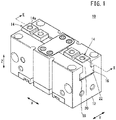
- the opening/closing chuck 10 includes a rectangular parallelepiped shaped body 12, and a pair of fingers 14 that are slidably supported in a longitudinal direction (the X direction) of the body 12.
- the opening/closing chuck 10 is used by connecting non-illustrated attachments for gripping a workpiece to the fingers 14. That which is shown by reference numeral 14a are screw holes used for connecting the attachments.
- the body 12 includes a cylinder chamber 24 at a lower central part in the longitudinal direction. Further, the body 12 has a guide groove 22 that extends in the longitudinal direction of the body 12, and both ends of which open on end surfaces of the body 12 at portions above the cylinder chamber 24.
- a piston 26 which is capable of sliding in a vertical direction (Z direction) is disposed in the cylinder chamber 24.
- the cylinder chamber 24 is partitioned into a first pressure chamber 24a formed on a lower side of the piston 26, and a second pressure chamber 24b formed on an upper side of the piston 26.
- the first pressure chamber 24a is closed by a cap 30.
- a piston rod 28 which is connected by a bolt 32 to the piston 26 extends further upward through the second pressure chamber 24b.
- An upper part of the piston rod 28 faces toward the guide groove 22 and constitutes a cam portion 28a of a known structure for driving the fingers 14.
- each of the fingers 14 has an inverted T-shaped cross section.
- Each of the fingers 14 includes a pair of overhanging portions 16 and 18 that project out laterally from the main body portion 20 over the entire length in the longitudinal direction (the X direction) of the fingers 14.
- the guide groove 22 of the body 12 has an inverted T-shaped cross section that conforms to the cross-sectional shape of the fingers 14. The fingers 14 slide while undergoing sliding movement inside the guide groove 22 of the body 12.
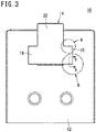
- upper surfaces 16a and 18a, side surfaces 16b and 18b, and lower surfaces 16c and 18c of the overhanging portions 16 and 18 face toward the wall surface of the guide groove 22 with a minute gap therebetween.
- a gap which is larger than the aforementioned minute gap exists between the side surfaces 20a and 20b of the main body portion 20 and the wall surfaces of the guide groove 22.
- the bottom surface 20c of the main body portion 20 lies substantially flush with the lower surfaces 16c and 18c of the overhanging portions 16 and 18.
- Stepped portions 22a exists between the wall surface of the guide groove 22 facing toward the bottom surface 20c of the main body portion 20, and the wall surfaces of the guide groove 22 facing toward the lower surfaces 16c and 18c of the overhanging portions 16 and 18 (see FIG. 6B ).
- Outer peripheral surfaces of the respective overhanging portions 16 and 18 of the fingers 14 are made up from five surfaces including the upper surfaces 16a and 18a, the side surfaces 16b and 18b, the lower surfaces 16c and 18c, first end surfaces (end surfaces in the direction X1) 16d and 18d, and second end surfaces (end surfaces in the direction X2) 16e and 18e.
- the upper surfaces 16a and 18a and the lower surfaces 16c and 18c of the respective overhanging portions 16 and 18 are perpendicular to the side surfaces 20a and 20b of the main body portion 20, and are perpendicular to the side surfaces 16b and 18b of the overhanging portions 16 and 18.
- Crowning is applied to the intersections between the above-described five surfaces. More specifically, crowning is applied to the intersections between the upper surfaces 16a and 18a and the first end surfaces 16d and 18d, to the intersections between the side surfaces 16b and 18b and the first end surfaces 16d and 18d, and to the intersections between the lower surfaces 16c and 18c and the first end surfaces 16d and 18d. Similarly, crowning is applied to the intersections between the upper surfaces 16a and 18a and the second end surfaces 16e and 18e, to the intersections between the side surfaces 16b and 18b and the second end surfaces 16e and 18e, and to the intersections between the lower surfaces 16c and 18c and the second end surfaces 16e and 18e. Further, crowning is also applied to the intersections between the upper surfaces 16a and 18a and the side surfaces 16b and 18b, and to the intersections between the lower surfaces 16c and 18c and the side surfaces 16b and 18b.
- gaps are formed between the overhanging portions 16 and 18 of the fingers 14 and the wall surfaces of the guide groove 22, in a manner so as to continuously and gently expand from portions where both members are in contact.
- the meaning of "gaps are formed in a manner so as to continuously and gently expand from portions where both members are in contact” is supplemented as follows (the same applies to other locations of the same description given in the present specification).
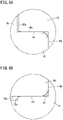
- Crowning is applied to a region including from a starting point of the boundary to a conceivable end point, and is formed so as to draw a gentle curve across the entire region. More specifically, it is necessary to prevent locations from being generated where angles (corners) are formed in the regions where the fingers are placed in contact with the body. Crowning, which is applied to the intersection between the first end surface 16d and the lower surface 16c of the overhanging portion 16, is shown in FIG. 5 . Crowning, which is applied to the intersection between the side surface 16b and the upper surface 16a of the overhanging portion 16, is shown in FIG. 6A . Crowning, which is applied to the intersection between the side surface 16b and the lower surface 16c of the overhanging portion 16, is shown in FIG. 6B .
- crowning is applied to the intersections between the wall surfaces facing toward the upper surfaces 16a and 18a of the overhanging portions 16 and 18 and the wall surfaces facing toward the side surfaces 20a and 20b of the main body portion 20. Furthermore, crowning is also applied to locations where the stepped portions 22a face toward the lower surfaces 16c and 18c of the overhanging portions 16 and 18.
- crownings are formed between the overhanging portions 16 and 18 of the fingers 14 and the wall surfaces of the guide groove 22, in a manner so as to continuously and gently expand from portions where both members are in contact.
- Crowning which is applied to the intersection between the wall surface of the guide groove 22 facing toward the upper surface 16a of the overhanging portion 16 and the wall surface of the guide groove 22 facing toward the side surface 20a of the main body portion 20, is shown in FIG. 6A .
- Crowning which is applied to a location where the stepped portion 22a faces toward the lower surface 16c of the overhanging portion 16, is shown in FIG. 6B .
- a pitch moment (a moment about the Y axis) acts on the fingers 14. Further, there may be cases in which loads in the vertical direction (in the Z direction), loads in the lateral direction (in the Y direction), a roll moment (a moment about the X axis), and a yaw moment (a moment about the Z axis) act on the fingers 14.
- the crowning applied to the intersections between the upper surfaces 16a and 18a and the first end surfaces 16d and 18d, and to the intersections between the lower surfaces 16c and 18c and the first end surfaces 16d and 18d alleviates concentration of stress primarily when a pitch moment acts on the fingers 14.
- the crowning applied to the intersections between the upper surfaces 16a and 18a and the second end surfaces 16e and 18e, and to the intersections between the lower surfaces 16c and 18c and the second end surfaces 16e and 18e alleviates concentration of stress primarily when a pitch moment acts on the fingers 14.
- the value of R1/L preferably lies within a range of 0.1 to 27.
- the crowning applied to the intersections between the upper surfaces 16a and 18a and the side surfaces 16b and 18b, and to the intersections between the lower surfaces 16c and 18c and the side surfaces 16b and 18b alleviates concentration of stress primarily when a roll moment acts on the fingers 14.
- R2 the radius of curvature of these crownings
- W the length of the overhanging portions 16 and 18 in the widthwise direction (the Y direction)
- W the value of R2/W preferably lies within a range of 0.1 to 27.
- the crowning applied to the guide groove 22 of the body 12 also alleviates concentration of stress when a roll moment acts on the fingers 14.
- the crowning applied to the intersections between the side surfaces 16b and 18b and the first end surfaces 16d and 18d, and to the intersections between the side surfaces 16b and 18b and the second end surfaces 16e and 18e alleviates concentration of stress primarily when a yaw moment acts on the fingers 14.
- R3 the radius of curvature of these crownings
- L the length of the overhanging portions 16 and 18 in the longitudinal direction
- the crowning applied to the intersections between the lower surfaces 16c and 18c and the first end surfaces 16d and 18d alleviates concentration of stress when loads in the vertical direction act on the fingers 14.
- the crowning applied to the intersections between the lower surfaces 16c and 18c and the second end surfaces 16e and 18e, and to the intersections between the lower surfaces 16c and 18c and the side surfaces 16b and 18b also alleviates concentration of stress when loads in the vertical direction act on the fingers 14.
- the crowning applied to the guide groove 22 of the body 12 the crowning applied to portions where the stepped portions 22a face toward the lower surfaces 16c and 18c of the overhanging portions 16 and 18 also alleviates concentration of stress when loads in the vertical direction act on the fingers 14.
- the crowning applied to the intersections between the side surfaces 16b and 18b and the first end surfaces 16d and 18d alleviates concentration of stress when loads in the lateral direction act on the fingers 14.
- the crowning applied to the intersections between the side surfaces 16b and 18b and the second end surfaces 16e and 18e, to the intersections between the upper surfaces 16a and 18a and the side surfaces 16b and 18b, and to the intersections between the lower surfaces 16c and 18c and the side surfaces 16b and 18b also alleviates concentration of stress when loads in the lateral direction act on the fingers 14.
- crowning is applied to the intersections between the five surfaces including the upper surfaces 16a and 18a, the side surfaces 16b and 18b, the lower surfaces 16c and 18c, the first end surfaces 16d and 18d, and the second end surfaces 16e and 18e that make up the outer peripheral surfaces of the overhanging portions 16 and 18 of the fingers 14. Further, crowning is applied to a predetermined location of the guide groove 22 of the body 12. Therefore, it is possible to alleviate concentration of stress when moments about the three axes or loads in a vertical direction act on the fingers 14.
- This crowning process involves application of all of the aforementioned crownings, by a combination of performing grinding with respect to the side surfaces 16b and 18b of the pair of overhanging portions 16 and 18, and performing grinding with respect to the upper surfaces 16a and 18a and the lower surfaces 16c and 18c of the pair of overhanging portions 16 and 18.
- Grinding with respect to the side surfaces 16b and 18b of the pair of overhanging portions 16 and 18 is performed using a first machining tool 34 made up from a grindstone or an end mill.
- Grinding with respect to the upper surfaces 16a and 18a and the lower surfaces 16c and 18c of the pair of overhanging portions 16 and 18 is performed using a second machining tool 36 made up from a grindstone or an end mill.
- the first machining tool 34 which is a rotating body, is made so that the shape of a surface thereof, which is in contact with the workpiece to be machined, matches the shapes of the side surfaces 16b and 18b of the target overhanging portions 16 and 18.
- the first machining tool 34 includes crowning machining portions 34a on both ends thereof.
- the first machining tool 34 is arranged so that an axis thereof is arranged so as to be oriented along the Z direction, and can be rotationally driven about such an axis. Further, the first machining tool 34 is capable of being freely moved in the X direction and the Y direction. It should be noted that, in FIG. 7 , one of the fingers 14 having a shape after the crowning process has been performed thereon is shown for the sake of convenience.
- the second machining tool 36 which is a rotating body, is made so that the shape of a surface thereof, which is in contact with the workpiece to be machined, matches the shapes of the upper surfaces 16a and 18a and the lower surfaces 16c and 18c of the target overhanging portions 16 and 18.
- the second machining tool 36 includes a crowning machining portion 36a on one end thereof.
- the second machining tool 36 is arranged so that an axis thereof is arranged so as to be oriented along the Y direction, and can be rotationally driven about such an axis. Further, the second machining tool 36 is capable of being freely moved in the X direction and the Z direction.
- the fingers 14 are fixed to a clamp base 38 in a posture with the pair of overhanging portions 16 and 18 facing upward.
- the first machining tool 34 is placed in a retracted position separated away from the side surface 16b by a predetermined distance midway along the longitudinal direction (the X direction) of the side surface 16b of one of the overhanging portions 16.
- the second machining tool 36 is placed in a retracted position separated away from the lower surface 18c by a predetermined distance midway along the longitudinal direction (the X direction) of the lower surface 18c of another of the overhanging portions 18.
- the first machining tool 34 is made to move in the Y2 direction and approach toward the side surface 16b of the one of the overhanging portions 16, and is brought into contact at a predetermined pressure with the side surface 16b.
- the side surface 16b of the one of the overhanging portions 16 at a site where the first machining tool 34 is placed in contact therewith is subjected to grinding.
- the first machining tool 34 is made to move in a circling manner around the outer sides thereof.
- the first machining tool 34 is made to move in the X1 direction along the side surface 16b of the one of the overhanging portions 16 until arriving in the vicinity of the first end surface 16d. Thereafter, the first machining tool 34 is made to move in the Y2 direction until arriving in the vicinity of the side surface 18b of the other of the overhanging portions 18 while remaining at a distance from the finger 14, and furthermore, is made to move in the X2 direction until arriving in the vicinity of the second end surface 18e along the side surface 18b of the other of the overhanging portions 18.
- the first machining tool 34 is made to move in the Y1 direction until arriving in the vicinity of the side surface 16b of the one of the overhanging portions 16 while remaining at a distance from the finger 14, and thereafter, is made to move in the X1 direction along the side surface 16b of the one of the overhanging portions 16 until being returned to its original position.
- grinding is performed while controlling the amount of traveling in the X1 direction and the amount of traveling in the Y2 direction of the first machining tool 34 toward a target shape. Further, in order for crowning to be applied to the intersection between the side surface 18b and the first end surface 18d of the other of the overhanging portions 18, at the intersection, grinding is performed while controlling the amount of traveling in the X2 direction and the amount of traveling in the Y2 direction of the first machining tool 34 toward a target shape.
- grinding is performed while controlling the amount of traveling in the X2 direction and the amount of traveling in the Y1 direction of the first machining tool 34 toward a target shape. Further, in order for crowning to be applied to the intersection between the side surface 16b and the second end surface 16e of the one of the overhanging portions 16, at the intersection, grinding is performed while controlling the amount of traveling in the X1 direction and the amount of traveling in the Y1 direction of the first machining tool 34 toward a target shape.
- the second machining tool 36 is made to move in the Z1 direction and approach toward the lower surface 18c of the other of the overhanging portions 18, and is brought into contact at a predetermined pressure with the lower surface 18c.
- the lower surface 18c of the other of the overhanging portions 18 at a site where the second machining tool 36 is placed in contact therewith is subjected to grinding.
- the second machining tool 36 is made to move in a circling manner around the outer sides thereof.
- the second machining tool 36 is made to move in the X1 direction along the lower surface 18c of the other of the overhanging portions 18 until arriving in the vicinity of the first end surface 18d. Thereafter, the second machining tool 36 is made to move in the Z1 direction until arriving in the vicinity of the upper surface 18a while remaining at a distance from the finger 14. Furthermore, the second machining tool 36 is made to move in the X2 direction along the upper surface 18a until arriving in the vicinity of the second end surface 18e. Next, the second machining tool 36 is made to move in the Z2 direction until arriving in the vicinity of the lower surface 18c while remaining at a distance from the finger 14. Thereafter, the second machining tool 36 is made to move in the X1 direction along the lower surface 18c until being returned to its original position.
- grinding is performed while controlling the amount of traveling in the X2 direction and the amount of traveling in the Z2 direction of the second machining tool 36 toward a target shape. Further, in order for crowning to be applied to the intersection between the lower surface 18c and the second end surface 18e, at the intersection, grinding is performed while controlling the amount of traveling in the X1 direction and the amount of traveling in the Z2 direction of the second machining tool 36 toward a target shape.
- the clamp base 38 is rotated 180 degrees in the horizontal plane so that the second machining tool 36 is positioned in facing relation to the lower surface 16c of the one of the overhanging portions 16.
- the second machining tool 36 is made to move in the Z1 direction and approach toward the lower surface 16c of the one of the overhanging portions 16, and is brought into contact at a predetermined pressure with the lower surface 16c.
- the lower surface 16c of the one of the overhanging portions 16 at a site where the second machining tool 36 is placed in contact therewith is subjected to grinding.
- the second machining tool 36 is made to move in a circling manner around the outer sides thereof.
- the second machining tool 36 is made to move in the X2 direction along the lower surface 16c of the one of the overhanging portions 16 until arriving in the vicinity of the second end surface 16e. Thereafter, the second machining tool 36 is made to move in the Z1 direction until arriving in the vicinity of the upper surface 16a while remaining at a distance from the finger 14. Furthermore, the second machining tool 36 is made to move in the X1 direction along the upper surface 16a until arriving in the vicinity of the first end surface 16d. Next, the second machining tool 36 is made to move in the Z2 direction until arriving in the vicinity of the lower surface 16c while remaining at a distance from the finger 14. Thereafter, the second machining tool 36 is made to move in the X2 direction along the lower surface 16c until being returned to its original position.
- the amount of traveling in the X direction and the amount of traveling in the Z direction of the second machining tool 36 is controlled, in the same manner as in the case of the other of the overhanging portions 18, at the intersection between the lower surface 16c and the second end surface 16e, at the intersection between the upper surface 16a and the second end surface 16e, at the intersection between the upper surface 16a and the first end surface 16d, and at the intersection between the lower surface 16c and the first end surface 16d.
- FIGS. 10 to 13 a description will be given with reference to FIGS. 10 to 13 concerning a method of manufacturing an opening/closing chuck 40 and fingers 42 thereof according to a second embodiment of the present invention.
- the shape of the pair of overhanging portions of the fingers and the shape of the guide groove of the body differ from those of the opening/closing chuck 10 according to the first embodiment.
- each of the fingers 42 includes a pair of trapezoidal overhanging portions 44 and 46 which project out laterally from a main body portion 48 over the entire length thereof in the longitudinal direction.
- Upper surfaces 44a and 46a and lower surfaces 44c and 46c of each of the overhanging portions 44 and 46 are formed as tapered surfaces, which are inclined so as to come into closer proximity to each other toward side surfaces 44b and 46b.
- a guide groove 50 of the body 12 includes a cross-sectional shape that conforms to the cross-sectional shape of the fingers 42.
- the upper surfaces 44a and 46a, the side surfaces 44b and 46b, and the lower surfaces 44c and 46c of the respective overhanging portions 44 and 46 face toward the wall surface of the guide groove 50 with a minute gap therebetween.
- the bottom surface 48c of the main body portion 48 also faces toward the wall surface of the guide groove 50 with a minute gap therebetween.
- Crowning is applied to the intersections between the five surfaces including the upper surfaces 44a and 46a, the side surfaces 44b and 46b, the lower surfaces 44c and 46c, the first end surfaces 44d and 46d, and the second end surfaces 44e and 46e that make up the outer peripheral surfaces of the respective overhanging portions 44 and 46. More specifically, crowning is applied to the intersections between the upper surfaces 44a and 46a and the first end surfaces 44d and 46d, to the intersections between the side surfaces 44b and 46b and the first end surfaces 44d and 46d, and to the intersections between the lower surfaces 44c and 46c and the first end surfaces 44d and 46d.
- crowning is applied to the intersections between the upper surfaces 44a and 46a and the second end surfaces 44e and 46e, to the intersections between the side surfaces 44b and 46b and the second end surfaces 44e and 46e, and to the intersections between the lower surfaces 44c and 46c and the second end surfaces 44e and 46e. Further, crowning is also applied to the intersections between the upper surfaces 44a and 46a and the side surfaces 44b and 46b, and to the intersections between the lower surfaces 44c and 46c and the side surfaces 44b and 46b.
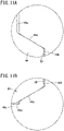
- gaps are formed between the overhanging portions 44 and 46 of the fingers 42 and the wall surfaces of the guide groove 50, in a manner so as to continuously and gently expand from portions where both members are in contact. Crowning that is applied to the intersection between the side surface 44b and the upper surface 44a of the overhanging portion 44 is shown in FIG. 11A . Crowning that is applied to the intersection between the side surface 44b and the lower surface 44c of the overhanging portion 44 is shown in FIG. 11B .
- crowning is applied to the intersections between the wall surfaces facing toward the upper surfaces 44a and 46a of the overhanging portions 44 and 46 and the wall surfaces facing toward the side surfaces 48a and 48b of the main body portion 48. Furthermore, crowning is also applied to locations where stepped portions 50a face toward the lower surfaces 44c and 46c of the overhanging portions 44 and 46.
- gaps are formed between the overhanging portions 44 and 46 of the fingers 42 and the wall surfaces of the guide groove 50, in a manner so as to continuously and gently expand from portions where both members are in contact. Crowning that is applied to the intersection between the wall surface of the guide groove 50 facing toward the upper surface 44a of the overhanging portion 44 and the wall surface of the guide groove 50 facing toward the side surface 48a of the main body portion 48 is shown in FIG. 11A . Crowning that is applied to a location where the stepped portion 50a faces toward the lower surface 44c of the overhanging portion 44 is shown in FIG. 11B .
- crowning is applied to the intersections between the five surfaces including the upper surfaces 44a and 46a, the side surfaces 44b and 46b, the lower surfaces 44c and 46c, the first end surfaces 44d and 46d, and the second end surfaces 44e and 46e that make up the outer peripheral surfaces of the overhanging portions 44 and 46 of the fingers 42. Further, crowning is applied to a predetermined location of the guide groove 50 of the body 12. Therefore, it is possible to alleviate concentration of stress when moments about the three axes or loads in a vertical direction act on the fingers.
- a description will be given with reference to FIGS. 12 and 13 concerning a method (a crowning process) of applying crowning to the fingers 42.
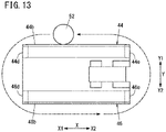
- a crowning process using a third machining tool 52 (a single machining tool) made up from a grindstone or an end mill, grinding is performed with respect to the side surfaces 44b and 46b of the pair of overhanging portions 44 and 46, grinding is simultaneously performed with respect to the upper surfaces 44a and 46a and the lower surfaces 44c and 46c of the pair of overhanging portions 44 and 46, and all of the aforementioned crowning is applied.
- the third machining tool 52 which is a rotating body, is made so that the shape of a surface thereof, which is in contact with the workpiece to be machined, matches the shapes of the upper surfaces 44a and 46a, the side surfaces 44b and 46b, and the lower surfaces 44c and 46c of the target overhanging portions 44 and 46.
- the third machining tool 52 is arranged so that an axis thereof is arranged so as to be oriented along the Z direction, and can be rotationally driven about such an axis. Further, the third machining tool 52 is capable of being freely moved in the X direction and the Y direction.
- the third machining tool 52 has a first crowning machining portion 52a and a second crowning machining portion 52b.
- the first crowning machining portion 52a is a machining portion in order to apply crowning to intersections between the upper surfaces 44a and 46a and the side surfaces 44b and 46b of the overhanging portions 44 and 46.
- the second crowning machining portion 52b is a machining portion in order to apply crowning to intersections between the lower surfaces 44c and 46c and the side surfaces 44b and 46b of the overhanging portions 44 and 46.
- the fingers 42 are fixed to the clamp base 38 in a posture in which the pair of overhanging portions 44 and 46 face upward.
- the third machining tool 52 is at a position in confronting relation to the overhanging portion 44 midway along the longitudinal direction (the X direction) of one of the overhanging portions 44.
- the third machining tool 52 is made to move in the Y2 direction and approach toward the one of the overhanging portions 44, and is brought into contact at a predetermined pressure with the upper surface 44a, the side surface 44b, and the lower surface 44c.
- the upper surface 44a, the side surface 44b, and the lower surface 44c of the one of the overhanging portions 44 at a site where the third machining tool 52 is placed in contact therewith are simultaneously subjected to grinding.
- the third machining tool 52 is made to move in a circling manner around the outer sides thereof.
- the third machining tool 52 is made to move in the X1 direction along the side surface 44b etc. of the one of the overhanging portions 44 until arriving in the vicinity of the first end surface 44d. Thereafter, the third machining tool 52 is moved in the Y2 direction until arriving in the vicinity of the side surface 46b of the other of the overhanging portions 46 while remaining at a distance from the finger 42. Furthermore, the third machining tool 52 is made to move in the X2 direction along the side surface 46b of the other of the overhanging portions 46 until arriving in the vicinity of the second end surface 46e.
- the third machining tool 52 is moved in the Y1 direction until arriving in the vicinity of the side surface 44b of the one of the overhanging portions 44 while remaining at a distance from the finger 42. Thereafter, the third machining tool 52 is moved in the X1 direction along the side surface 44b or the like of the one of the overhanging portions 44 until being returned to its original position.
- crowning is applied to the intersection between the upper surface 44a and the first end surface 44d, to the intersection between the side surface 44b and the first end surface 44d, and to the intersection between the lower surface 44c and the first end surface 44d. More specifically, at these intersections, grinding is performed while controlling the amount of traveling in the X1 direction and the amount of traveling in the Y2 direction of the third machining tool 52 toward a target shape.
- crowning is applied to the intersection between the upper surface 46a and the first end surface 46d, to the intersection between the side surface 46b and the first end surface 46d, and to the intersection between the lower surface 46c and the first end surface 46d. More specifically, at these intersections, grinding is performed while controlling the amount of traveling in the X2 direction and the amount of traveling in the Y2 direction of the third machining tool 52 toward a target shape.
- crowning is applied to the intersection between the upper surface 46a and the second end surface 46e, to the intersection between the side surface 46b and the second end surface 46e, and to the intersection between the lower surface 46c and the second end surface 46e. More specifically, at these intersections, grinding is performed while controlling the amount of traveling in the X2 direction and the amount of traveling in the Y1 direction of the third machining tool 52 toward a target shape.
- crowning is applied to the intersection between the upper surface 44a and the second end surface 44e, to the intersection between the side surface 44b and the second end surface 44e, and to the intersection between the lower surface 44c and the second end surface 44e. More specifically, at these intersections, grinding is performed while controlling the amount of traveling in the X1 direction and the amount of traveling in the Y1 direction of the third machining tool 52 toward a target shape.
- crowning can be applied to the intersections of the five surfaces that make up the outer peripheral surfaces of the pair of overhanging portions 44 and 46 of the fingers 42.
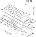
- each of the overhanging portions includes a recess and a grease reservoir.
- one of the overhanging portions 64 includes a recess 72 centrally in the longitudinal direction of the upper surface 64a, the side surface 64b, and the lower surface 64c, and includes crowning regions CR1 and CR2 at both ends of the recess 72.
- a grease reservoir 70 opens in a bottom surface of the recess 72 that is formed in the upper surface 64a.
- the other one of the overhanging portions 66 also includes a similar grease reservoir 70 therein. Grease that is stored in the grease reservoirs 70 is supplied to the sliding surfaces of the overhanging portions 64 and 66, and the lubricating function thereof is maintained.
- the grease reservoir 70 opens on the bottom surface of the recess 72, an edge portion of the grease reservoir 70 does not come into contact with the wall surface of the guide groove and cause concentration of stress to occur. Further, the recess 72 is connected, via the crowning regions CR1 and CR2 to which crowning was applied, to sliding surfaces (surfaces in contact with the wall surfaces of the guide groove) on the upper surface 64a, the side surface 64b, and the lower surface 64c. Therefore, due to the presence of the recess 72, concentration of stress within the guide groove does not occur.
- Crowning is applied to the intersections between the five surfaces including the upper surfaces 64a and 66a, the side surfaces 64b and 66b, the lower surfaces 64c and 66c, the first end surfaces 64d and 66d, and the second end surfaces 64e and 66e that make up the outer peripheral surfaces of the respective overhanging portions 64 and 66. Further, in the guide groove of the body 12, crowning is applied to the intersections between the wall surfaces facing toward the upper surfaces 64a and 66a of the overhanging portions 64 and 66 and the wall surfaces facing toward the side surfaces 68a and 68b of the main body portion 68. Further, crowning is also applied to locations where the stepped portions of the guide groove face toward the lower surfaces 64c and 66c of the overhanging portions 64 and 66.
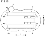
- the third machining tool 52 While being rotated about the axis thereof, the third machining tool 52 is brought into contact with the upper surface 64a, the side surface 64b, and the lower surface 64c at predetermined positions in the longitudinal direction (the X direction) of the one of the overhanging portions 64, and these surfaces are simultaneously subjected to grinding. In order to perform such grinding over the entirety of the one of the overhanging portions 64 and the entirety of the other of the overhanging portions 66, the third machining tool 52 is made to move in a circling manner around the outer sides thereof.
- grinding is performed while controlling the amount of traveling in the X direction and the amount of traveling in the Y direction of the third machining tool 52 toward a target shape.
- grinding is performed while controlling the amount of traveling in the Y1 direction and the amount of traveling in the Y2 direction of the third machining tool 52 toward a target shape.
- grinding is performed while controlling the amount of traveling in the Y1 direction and the amount of traveling in the Y2 direction of the third machining tool 52 toward a target shape.
- crowning can be applied to the intersections of the five surfaces that make up the outer peripheral surfaces of the pair of overhanging portions 64 and 66, together with enabling the crowning regions CR1 and CR2 and the recesses 72 to be formed on the pair of overhanging portions 64 and 66.
Landscapes
- Engineering & Computer Science (AREA)
- Mechanical Engineering (AREA)
- Robotics (AREA)
- Grinding And Polishing Of Tertiary Curved Surfaces And Surfaces With Complex Shapes (AREA)
- Manipulator (AREA)
- Stringed Musical Instruments (AREA)
- Gloves (AREA)
Abstract
Description
- The present invention relates to an opening/closing chuck equipped with a pair of fingers for gripping a workpiece, as well as a method for manufacturing the fingers.
- Conventionally, an opening/closing chuck has been known in which a pair of fingers for gripping a workpiece are slidably supported in directions to approach and separate away from each other. For example, in
JP 2003-526528 A - Further, in
EP 3563989 A1 , in a grip device equipped with a pair of slides, it is disclosed that ramps are provided on guide flanks of the respective slides. In accordance therewith, a wedge gap is formed that widens toward end surfaces of the slides. - When a workpiece is gripped using a pair of slidably supported fingers, due to a reaction force from the workpiece, a load in a predetermined direction (a vertical direction or a lateral direction) acts on the fingers. Further, moments act which attempt to rotate the fingers about various three-dimensional axes. The loads and the moments that act on the fingers increase as the gripping force on the workpiece increases. Further, the moments that act on the fingers increase as the distance between workpiece gripping positions on gripping members (attachments), which are provided to extend from the fingers, and the supported positions of the fingers become longer. When such loads or moments acting on the fingers are large, concentration of stress occurs on contact surfaces between the fingers and the body, excessive surface pressure is generated, and the fingers and the sliding surfaces of the body are damaged.
- However, a technique that takes into consideration concentration of stress generated in the fingers and the body has not yet been sufficiently developed. The technique disclosed in
EP 3563989 A1 is somewhat effective in relieving concentration of stress and preventing excessive surface pressure when opposing ends of a pair of slides attempt to rotate so as to open at an angle. However, the disclosed technique does not take into consideration that various three-dimensional axial moments act on the slides. - The present invention has the object of solving the aforementioned problem.
- An opening/closing chuck according to the present invention comprises a pair of fingers configured to slide inside of a guide groove of a body, and which are slidably supported in directions to approach toward and separate away from each other. The fingers each include a pair of overhanging portions configured to project out laterally from a main body portion, and outer peripheral surfaces of the overhanging portions are made up from five surfaces including upper surfaces, side surfaces, lower surfaces, first end surfaces, and second end surfaces. Crowning is applied to intersections between these surfaces.
- According to the above-described opening/closing chuck, concentration of stress generated in the fingers due to loads acting on the fingers in a vertical direction and moments about three axes can be alleviated, and a maximum surface pressure can be lowered.
- Further, in a first method of manufacturing according to the present invention, the fingers slide inside a guide groove of a body of an opening/closing chuck, are slidably supported in directions to approach toward and separate away from each other, and include a pair of overhanging portions configured to project out laterally from a main body portion. Outer peripheral surfaces of the overhanging portions are made up from five surfaces including upper surfaces, side surfaces, lower surfaces, first end surfaces, and second end surfaces, wherein the upper and lower surfaces are perpendicular to the side surfaces. The first method of manufacturing comprises a step of applying crowning at intersections of the five surfaces, by a combination of performing grinding with respect to the side surfaces by a first machining tool, and performing grinding with respect to the upper surfaces and the lower surfaces by a second machining tool.
- Further, in a second method of manufacturing according to the present invention, the fingers slide inside a guide groove of a body of an opening/closing chuck, are slidably supported in directions to approach toward and separate away from each other, and include a pair of overhanging portions configured to project out laterally from a main body portion. Outer peripheral surfaces of the overhanging portions are made up from five surfaces including upper surfaces, side surfaces, lower surfaces, first end surfaces, and second end surfaces, and the upper surfaces and the lower surfaces are tapered surfaces configured to come into closer proximity to each other toward the side surfaces. The second method of manufacturing comprises a step of applying crowning at intersections of the five surfaces, by performing grinding with respect to the side surfaces, and simultaneously performing grinding with respect to the upper surfaces and the lower surfaces using a single machining tool.
- According to the first method of manufacturing and the second method of manufacturing described above, the crowning process for alleviating the concentration of stress generated in the fingers and the body can be easily performed in a fewer number of steps. The above-described concentration of stress is caused by loads acting on the fingers in the vertical direction and moments about the three axes.
- In the opening/closing chuck according to the present invention, crowning is applied to the intersections of the five surfaces including the upper surfaces, the side surfaces, the lower surfaces, the first end surfaces, and the second end surfaces that make up the outer peripheral surfaces of the overhanging portions of the fingers. Therefore, it is possible to alleviate concentration of stress when moments about the three axes or loads in a vertical direction act on the fingers.
- Further, in the first method of manufacturing the fingers according to the present invention, grinding with respect to the side surfaces of the overhanging portions by the first machining tool, and grinding with respect to the upper surfaces and the lower surfaces of the overhanging portions by the second machining tool are combined. Consequently, since crowning is applied to the intersections of the five surfaces of the overhanging portions, the crowning process can be easily performed in a fewer number of steps.
- Further, in the second method of manufacturing the fingers according to the present invention, using a single machining tool, grinding is performed with respect to the side surfaces of the overhanging portions and simultaneously grinding is performed with respect to the upper surfaces and the lower surfaces of the overhanging portions. Consequently, since crowning is applied to the intersections of the five surfaces of the overhanging portions, the crowning process can be easily performed in an even fewer number of steps.
- The above and other objects, features, and advantages of the present invention will become more apparent from the following description when taken in conjunction with the accompanying drawings, in which preferred embodiments of the present invention are shown by way of illustrative example.
-
-
FIG. 1 shows an external perspective view of an opening/closing chuck according to a first embodiment of the present invention; -
FIG. 2 is a cross-sectional view taken along line II-II of the opening/closing chuck shown inFIG. 1 ; -
FIG. 3 is a front view of the opening/closing chuck shown inFIG. 1 ; -
FIG. 4 is an external perspective view of a finger of the opening/closing chuck shown inFIG. 1 ; -
FIG. 5 is a diagram showing a portion of a cross section of a finger and a body taken along line V-V ofFIG. 3 ; -
FIG. 6A is an enlarged view of a portion A shown inFIG. 3 ; -
FIG. 6B is an enlarged view of a portion B shown inFIG. 3 ; -
FIG. 7 is a diagram schematically showing a method of applying crowning to the finger shown inFIG. 4 ; -
FIG. 8 is a diagram schematically showing a path over which a first machining tool is made to move when crowning is applied to the finger shown inFIG. 4 ; -
FIG. 9 is a diagram schematically showing a path over which a second machining tool is made to move when crowning is applied to the finger shown inFIG. 4 ; -
FIG. 10 is a front view of an opening/closing chuck according to a second embodiment of the present invention; -
FIG. 11A is an enlarged view of a portion C shown inFIG. 10 ; -
FIG. 11B is an enlarged view of a portion D shown inFIG. 10 ; -
FIG. 12 is a diagram schematically showing a method of applying crowning to the finger shown inFIG. 10 ; -
FIG. 13 is a diagram schematically showing a path over which a third machining tool is made to move when crowning is applied to the finger of the opening/closing chuck shown inFIG. 10 ; -
FIG. 14 is a perspective view of a finger of an opening/closing chuck according to a third embodiment of the present invention; and -
FIG. 15 is a diagram schematically showing a path over which a third machining tool is made to move when crowning is applied to the finger shown inFIG. 14 . - In the description given below, when terms related to the up, down, left, and right directions are used, the terms refer to the directions shown in the drawings for the sake of convenience, and such terms are not intended to limit the actual arrangement or the like of the respective constituent members.
- A description will be given with reference to
FIGS. 1 to 6 concerning an opening/closing chuck 10 according to the first embodiment of the present invention. As shown inFIGS. 1 and2 , the opening/closing chuck 10 includes a rectangular parallelepipedshaped body 12, and a pair offingers 14 that are slidably supported in a longitudinal direction (the X direction) of thebody 12. The opening/closing chuck 10 is used by connecting non-illustrated attachments for gripping a workpiece to thefingers 14. That which is shown byreference numeral 14a are screw holes used for connecting the attachments. - The
body 12 includes acylinder chamber 24 at a lower central part in the longitudinal direction. Further, thebody 12 has aguide groove 22 that extends in the longitudinal direction of thebody 12, and both ends of which open on end surfaces of thebody 12 at portions above thecylinder chamber 24. Apiston 26 which is capable of sliding in a vertical direction (Z direction) is disposed in thecylinder chamber 24. Thecylinder chamber 24 is partitioned into afirst pressure chamber 24a formed on a lower side of thepiston 26, and asecond pressure chamber 24b formed on an upper side of thepiston 26. Thefirst pressure chamber 24a is closed by acap 30. - A
piston rod 28 which is connected by abolt 32 to thepiston 26 extends further upward through thesecond pressure chamber 24b. An upper part of thepiston rod 28 faces toward theguide groove 22 and constitutes acam portion 28a of a known structure for driving thefingers 14. When air is supplied to thefirst pressure chamber 24a and the air in thesecond pressure chamber 24b is discharged, thepiston 26 and thepiston rod 28 are moved upward. Consequently, the pair offingers 14 slide in directions away from each other. When air is supplied to thesecond pressure chamber 24b and the air in thefirst pressure chamber 24a is discharged, thepiston 26 and thepiston rod 28 are moved downward. Consequently, the pair offingers 14 slide in directions to approach one another. - As shown in
FIG. 3 andFIG. 4 , each of thefingers 14 has an inverted T-shaped cross section. Each of thefingers 14 includes a pair of overhangingportions main body portion 20 over the entire length in the longitudinal direction (the X direction) of thefingers 14. Theguide groove 22 of thebody 12 has an inverted T-shaped cross section that conforms to the cross-sectional shape of thefingers 14. Thefingers 14 slide while undergoing sliding movement inside theguide groove 22 of thebody 12. - In order to enable the sliding movement of the
fingers 14,upper surfaces lower surfaces portions guide groove 22 with a minute gap therebetween. A gap which is larger than the aforementioned minute gap exists between the side surfaces 20a and 20b of themain body portion 20 and the wall surfaces of theguide groove 22. - The
bottom surface 20c of themain body portion 20 lies substantially flush with thelower surfaces portions portions 22a exists between the wall surface of theguide groove 22 facing toward thebottom surface 20c of themain body portion 20, and the wall surfaces of theguide groove 22 facing toward thelower surfaces portions 16 and 18 (seeFIG. 6B ). - Outer peripheral surfaces of the respective overhanging
portions fingers 14 are made up from five surfaces including theupper surfaces lower surfaces upper surfaces lower surfaces portions main body portion 20, and are perpendicular to the side surfaces 16b and 18b of the overhangingportions - Crowning is applied to the intersections between the above-described five surfaces. More specifically, crowning is applied to the intersections between the
upper surfaces lower surfaces upper surfaces lower surfaces upper surfaces lower surfaces - In these crownings, gaps are formed between the overhanging
portions fingers 14 and the wall surfaces of theguide groove 22, in a manner so as to continuously and gently expand from portions where both members are in contact. In this instance, the meaning of "gaps are formed in a manner so as to continuously and gently expand from portions where both members are in contact" is supplemented as follows (the same applies to other locations of the same description given in the present specification). When the fingers are placed in contact with the body under a strong pressure, one or both of the fingers and the body are elastically deformed, and the boundary between the regions where both members are in contact and the regions where they are not in contact is moved. Crowning is applied to a region including from a starting point of the boundary to a conceivable end point, and is formed so as to draw a gentle curve across the entire region. More specifically, it is necessary to prevent locations from being generated where angles (corners) are formed in the regions where the fingers are placed in contact with the body. Crowning, which is applied to the intersection between thefirst end surface 16d and thelower surface 16c of the overhangingportion 16, is shown inFIG. 5 . Crowning, which is applied to the intersection between theside surface 16b and theupper surface 16a of the overhangingportion 16, is shown inFIG. 6A . Crowning, which is applied to the intersection between theside surface 16b and thelower surface 16c of the overhangingportion 16, is shown inFIG. 6B . - Further, in the
guide groove 22 of thebody 12, crowning is applied to the intersections between the wall surfaces facing toward theupper surfaces portions main body portion 20. Furthermore, crowning is also applied to locations where the steppedportions 22a face toward thelower surfaces portions - In these crownings as well, gaps are formed between the overhanging
portions fingers 14 and the wall surfaces of theguide groove 22, in a manner so as to continuously and gently expand from portions where both members are in contact. Crowning, which is applied to the intersection between the wall surface of theguide groove 22 facing toward theupper surface 16a of the overhangingportion 16 and the wall surface of theguide groove 22 facing toward theside surface 20a of themain body portion 20, is shown inFIG. 6A . Crowning, which is applied to a location where the steppedportion 22a faces toward thelower surface 16c of the overhangingportion 16, is shown inFIG. 6B . - When the workpiece is gripped using the opening/
closing chuck 10, a pitch moment (a moment about the Y axis) acts on thefingers 14. Further, there may be cases in which loads in the vertical direction (in the Z direction), loads in the lateral direction (in the Y direction), a roll moment (a moment about the X axis), and a yaw moment (a moment about the Z axis) act on thefingers 14. - The crowning applied to the intersections between the
upper surfaces lower surfaces fingers 14. The crowning applied to the intersections between theupper surfaces lower surfaces fingers 14. Assuming that the radius of curvature of these crownings is indicated by R1, and the length of the overhangingportions - The crowning applied to the intersections between the
upper surfaces lower surfaces fingers 14. Assuming that the radius of curvature of these crownings is indicated by R2, and the length of the overhangingportions guide groove 22 of thebody 12 also alleviates concentration of stress when a roll moment acts on thefingers 14. - The crowning applied to the intersections between the side surfaces 16b and 18b and the first end surfaces 16d and 18d, and to the intersections between the side surfaces 16b and 18b and the second end surfaces 16e and 18e alleviates concentration of stress primarily when a yaw moment acts on the
fingers 14. Assuming that the radius of curvature of these crownings is indicated by R3, and the length of the overhangingportions - The crowning applied to the intersections between the
lower surfaces fingers 14. The crowning applied to the intersections between thelower surfaces lower surfaces fingers 14. Among the crowning applied to theguide groove 22 of thebody 12, the crowning applied to portions where the steppedportions 22a face toward thelower surfaces portions fingers 14. - The crowning applied to the intersections between the side surfaces 16b and 18b and the first end surfaces 16d and 18d alleviates concentration of stress when loads in the lateral direction act on the
fingers 14. The crowning applied to the intersections between the side surfaces 16b and 18b and the second end surfaces 16e and 18e, to the intersections between theupper surfaces lower surfaces fingers 14. - In accordance with the opening/
closing chuck 10 according to the present embodiment, crowning is applied to the intersections between the five surfaces including theupper surfaces lower surfaces portions fingers 14. Further, crowning is applied to a predetermined location of theguide groove 22 of thebody 12. Therefore, it is possible to alleviate concentration of stress when moments about the three axes or loads in a vertical direction act on thefingers 14. - Next, a description will be given with reference to
FIGS. 7 to 9 concerning a method of manufacturing thefingers 14 of the opening/closing chuck 10, and more specifically, concerning a method (a crowning process) of applying crowning to thefingers 14. - This crowning process involves application of all of the aforementioned crownings, by a combination of performing grinding with respect to the side surfaces 16b and 18b of the pair of overhanging
portions upper surfaces lower surfaces portions portions first machining tool 34 made up from a grindstone or an end mill. Grinding with respect to theupper surfaces lower surfaces portions second machining tool 36 made up from a grindstone or an end mill. - As shown in
FIG. 7 , thefirst machining tool 34, which is a rotating body, is made so that the shape of a surface thereof, which is in contact with the workpiece to be machined, matches the shapes of the side surfaces 16b and 18b of thetarget overhanging portions first machining tool 34 includes crowningmachining portions 34a on both ends thereof. Thefirst machining tool 34 is arranged so that an axis thereof is arranged so as to be oriented along the Z direction, and can be rotationally driven about such an axis. Further, thefirst machining tool 34 is capable of being freely moved in the X direction and the Y direction. It should be noted that, inFIG. 7 , one of thefingers 14 having a shape after the crowning process has been performed thereon is shown for the sake of convenience. - In the same manner, the
second machining tool 36, which is a rotating body, is made so that the shape of a surface thereof, which is in contact with the workpiece to be machined, matches the shapes of theupper surfaces lower surfaces target overhanging portions second machining tool 36 includes a crowningmachining portion 36a on one end thereof. Thesecond machining tool 36 is arranged so that an axis thereof is arranged so as to be oriented along the Y direction, and can be rotationally driven about such an axis. Further, thesecond machining tool 36 is capable of being freely moved in the X direction and the Z direction. - When the crowning process is performed, first, the
fingers 14 are fixed to aclamp base 38 in a posture with the pair of overhangingportions first machining tool 34 is placed in a retracted position separated away from theside surface 16b by a predetermined distance midway along the longitudinal direction (the X direction) of theside surface 16b of one of the overhangingportions 16. Further, thesecond machining tool 36 is placed in a retracted position separated away from thelower surface 18c by a predetermined distance midway along the longitudinal direction (the X direction) of thelower surface 18c of another of the overhangingportions 18. - Next, while being rotated about the axis thereof, the
first machining tool 34 is made to move in the Y2 direction and approach toward theside surface 16b of the one of the overhangingportions 16, and is brought into contact at a predetermined pressure with theside surface 16b. In accordance therewith, theside surface 16b of the one of the overhangingportions 16 at a site where thefirst machining tool 34 is placed in contact therewith is subjected to grinding. In order to perform such grinding over theentire side surface 16b of the one of the overhangingportions 16 and theentire side surface 18b of the other of the overhangingportions 18, thefirst machining tool 34 is made to move in a circling manner around the outer sides thereof. - More specifically, as schematically shown in
FIG. 8 , thefirst machining tool 34 is made to move in the X1 direction along theside surface 16b of the one of the overhangingportions 16 until arriving in the vicinity of thefirst end surface 16d. Thereafter, thefirst machining tool 34 is made to move in the Y2 direction until arriving in the vicinity of theside surface 18b of the other of the overhangingportions 18 while remaining at a distance from thefinger 14, and furthermore, is made to move in the X2 direction until arriving in the vicinity of thesecond end surface 18e along theside surface 18b of the other of the overhangingportions 18. Next, thefirst machining tool 34 is made to move in the Y1 direction until arriving in the vicinity of theside surface 16b of the one of the overhangingportions 16 while remaining at a distance from thefinger 14, and thereafter, is made to move in the X1 direction along theside surface 16b of the one of the overhangingportions 16 until being returned to its original position. - When the
first machining tool 34 is moved, in order for crowning to be applied to the intersection between theside surface 16b and thefirst end surface 16d of the one of the overhangingportions 16, at the intersection, grinding is performed while controlling the amount of traveling in the X1 direction and the amount of traveling in the Y2 direction of thefirst machining tool 34 toward a target shape. Further, in order for crowning to be applied to the intersection between theside surface 18b and thefirst end surface 18d of the other of the overhangingportions 18, at the intersection, grinding is performed while controlling the amount of traveling in the X2 direction and the amount of traveling in the Y2 direction of thefirst machining tool 34 toward a target shape. Similarly, in order for crowning to be applied to the intersection between theside surface 18b and thesecond end surface 18e of the other of the overhangingportions 18, at the intersection, grinding is performed while controlling the amount of traveling in the X2 direction and the amount of traveling in the Y1 direction of thefirst machining tool 34 toward a target shape. Further, in order for crowning to be applied to the intersection between theside surface 16b and thesecond end surface 16e of the one of the overhangingportions 16, at the intersection, grinding is performed while controlling the amount of traveling in the X1 direction and the amount of traveling in the Y1 direction of thefirst machining tool 34 toward a target shape. - By causing the
first machining tool 34 to circle one time therearound, grinding with respect to the side surfaces 16b and 18b of the pair of overhangingportions first machining tool 34 is made to stop, and thefirst machining tool 34 is separated and retracted away from theside surface 16b of the one of the overhangingportions 16. - Next, while being rotated about the axis thereof, the
second machining tool 36 is made to move in the Z1 direction and approach toward thelower surface 18c of the other of the overhangingportions 18, and is brought into contact at a predetermined pressure with thelower surface 18c. In accordance therewith, thelower surface 18c of the other of the overhangingportions 18 at a site where thesecond machining tool 36 is placed in contact therewith is subjected to grinding. In order to perform such grinding over the entirelower surface 18c and the entireupper surface 18a of the other of the overhangingportions 18, thesecond machining tool 36 is made to move in a circling manner around the outer sides thereof. - More specifically, as schematically shown in
FIG. 9 , thesecond machining tool 36 is made to move in the X1 direction along thelower surface 18c of the other of the overhangingportions 18 until arriving in the vicinity of thefirst end surface 18d. Thereafter, thesecond machining tool 36 is made to move in the Z1 direction until arriving in the vicinity of theupper surface 18a while remaining at a distance from thefinger 14. Furthermore, thesecond machining tool 36 is made to move in the X2 direction along theupper surface 18a until arriving in the vicinity of thesecond end surface 18e. Next, thesecond machining tool 36 is made to move in the Z2 direction until arriving in the vicinity of thelower surface 18c while remaining at a distance from thefinger 14. Thereafter, thesecond machining tool 36 is made to move in the X1 direction along thelower surface 18c until being returned to its original position. - When the above-described
second machining tool 36 is moved, in order for crowning to be applied to the intersection between thelower surface 18c and thefirst end surface 18d, at the intersection, grinding is performed while controlling the amount of traveling in the X1 direction and the amount of traveling in the Z1 direction of thesecond machining tool 36 toward a target shape. Further, in order for crowning to be applied to the intersection between theupper surface 18a and thefirst end surface 18d, at the intersection, grinding is performed while controlling the amount of traveling in the X2 direction and the amount of traveling in the Z1 direction of thesecond machining tool 36 toward a target shape. Further, in order for crowning to be applied to the intersection between theupper surface 18a and thesecond end surface 18e, at the intersection, grinding is performed while controlling the amount of traveling in the X2 direction and the amount of traveling in the Z2 direction of thesecond machining tool 36 toward a target shape. Further, in order for crowning to be applied to the intersection between thelower surface 18c and thesecond end surface 18e, at the intersection, grinding is performed while controlling the amount of traveling in the X1 direction and the amount of traveling in the Z2 direction of thesecond machining tool 36 toward a target shape. - By causing the
second machining tool 36 to circle one time around the other of the overhangingportions 18, grinding with respect to theupper surface 18a and thelower surface 18c of the other of the overhangingportions 18 is completed. Rotation of thesecond machining tool 36 is made to stop, and thesecond machining tool 36 is separated and retracted away from thelower surface 18c of the other of the overhangingportions 18. - Next, the
clamp base 38 is rotated 180 degrees in the horizontal plane so that thesecond machining tool 36 is positioned in facing relation to thelower surface 16c of the one of the overhangingportions 16. Thereafter, while being rotated again about the axis thereof, thesecond machining tool 36 is made to move in the Z1 direction and approach toward thelower surface 16c of the one of the overhangingportions 16, and is brought into contact at a predetermined pressure with thelower surface 16c. In accordance therewith, thelower surface 16c of the one of the overhangingportions 16 at a site where thesecond machining tool 36 is placed in contact therewith is subjected to grinding. In order to perform such grinding over the entireupper surface 16a and the entirelower surface 16c of the one of the overhangingportions 16, thesecond machining tool 36 is made to move in a circling manner around the outer sides thereof. - More specifically, the
second machining tool 36 is made to move in the X2 direction along thelower surface 16c of the one of the overhangingportions 16 until arriving in the vicinity of thesecond end surface 16e. Thereafter, thesecond machining tool 36 is made to move in the Z1 direction until arriving in the vicinity of theupper surface 16a while remaining at a distance from thefinger 14. Furthermore, thesecond machining tool 36 is made to move in the X1 direction along theupper surface 16a until arriving in the vicinity of thefirst end surface 16d. Next, thesecond machining tool 36 is made to move in the Z2 direction until arriving in the vicinity of thelower surface 16c while remaining at a distance from thefinger 14. Thereafter, thesecond machining tool 36 is made to move in the X2 direction along thelower surface 16c until being returned to its original position. - When the
second machining tool 36 is moved, the amount of traveling in the X direction and the amount of traveling in the Z direction of thesecond machining tool 36 is controlled, in the same manner as in the case of the other of the overhangingportions 18, at the intersection between thelower surface 16c and thesecond end surface 16e, at the intersection between theupper surface 16a and thesecond end surface 16e, at the intersection between theupper surface 16a and thefirst end surface 16d, and at the intersection between thelower surface 16c and thefirst end surface 16d. - By causing the
second machining tool 36 to circle one time around the one of the overhangingportions 16, grinding with respect to theupper surface 16a and thelower surface 16c of the one of the overhangingportions 16 is completed. Rotation of thesecond machining tool 36 is made to stop, and thesecond machining tool 36 is separated and retracted away from thelower surface 16c of the one of the overhangingportions 16. Due to the steps described above, crowning can be applied to the intersections of the five surfaces that make up the outer peripheral surfaces of the pair of overhangingportions fingers 14. - Next, a description will be given with reference to
FIGS. 10 to 13 concerning a method of manufacturing an opening/closing chuck 40 andfingers 42 thereof according to a second embodiment of the present invention. In the opening/closing chuck 40 according to the second embodiment, the shape of the pair of overhanging portions of the fingers and the shape of the guide groove of the body differ from those of the opening/closing chuck 10 according to the first embodiment. - As shown in
FIGS. 10 and12 , each of thefingers 42 includes a pair of trapezoidal overhangingportions main body portion 48 over the entire length thereof in the longitudinal direction.Upper surfaces lower surfaces portions guide groove 50 of thebody 12 includes a cross-sectional shape that conforms to the cross-sectional shape of thefingers 42. In order to enable the sliding movement of thefingers 42, theupper surfaces lower surfaces portions guide groove 50 with a minute gap therebetween. Further, thebottom surface 48c of themain body portion 48 also faces toward the wall surface of theguide groove 50 with a minute gap therebetween. - Crowning is applied to the intersections between the five surfaces including the
upper surfaces lower surfaces portions upper surfaces lower surfaces upper surfaces lower surfaces upper surfaces lower surfaces - In these crownings, gaps are formed between the overhanging
portions fingers 42 and the wall surfaces of theguide groove 50, in a manner so as to continuously and gently expand from portions where both members are in contact. Crowning that is applied to the intersection between theside surface 44b and theupper surface 44a of the overhangingportion 44 is shown inFIG. 11A . Crowning that is applied to the intersection between theside surface 44b and thelower surface 44c of the overhangingportion 44 is shown inFIG. 11B . - Further, in the
guide groove 50 of thebody 12, crowning is applied to the intersections between the wall surfaces facing toward theupper surfaces portions main body portion 48. Furthermore, crowning is also applied to locations where steppedportions 50a face toward thelower surfaces portions - In these crownings, gaps are formed between the overhanging
portions fingers 42 and the wall surfaces of theguide groove 50, in a manner so as to continuously and gently expand from portions where both members are in contact. Crowning that is applied to the intersection between the wall surface of theguide groove 50 facing toward theupper surface 44a of the overhangingportion 44 and the wall surface of theguide groove 50 facing toward theside surface 48a of themain body portion 48 is shown inFIG. 11A . Crowning that is applied to a location where the steppedportion 50a faces toward thelower surface 44c of the overhangingportion 44 is shown inFIG. 11B . - In accordance with the opening/
closing chuck 40 according to the present embodiment, crowning is applied to the intersections between the five surfaces including theupper surfaces lower surfaces portions fingers 42. Further, crowning is applied to a predetermined location of theguide groove 50 of thebody 12. Therefore, it is possible to alleviate concentration of stress when moments about the three axes or loads in a vertical direction act on the fingers. - Next, a description will be given with reference to
FIGS. 12 and13 concerning a method (a crowning process) of applying crowning to thefingers 42. In this crowning process, using a third machining tool 52 (a single machining tool) made up from a grindstone or an end mill, grinding is performed with respect to the side surfaces 44b and 46b of the pair of overhangingportions upper surfaces lower surfaces portions - As shown in
FIG. 12 , thethird machining tool 52, which is a rotating body, is made so that the shape of a surface thereof, which is in contact with the workpiece to be machined, matches the shapes of theupper surfaces lower surfaces target overhanging portions third machining tool 52 is arranged so that an axis thereof is arranged so as to be oriented along the Z direction, and can be rotationally driven about such an axis. Further, thethird machining tool 52 is capable of being freely moved in the X direction and the Y direction. - The
third machining tool 52 has a firstcrowning machining portion 52a and a secondcrowning machining portion 52b. The firstcrowning machining portion 52a is a machining portion in order to apply crowning to intersections between theupper surfaces portions crowning machining portion 52b is a machining portion in order to apply crowning to intersections between thelower surfaces portions - When the crowning process is performed, first, the
fingers 42 are fixed to theclamp base 38 in a posture in which the pair of overhangingportions third machining tool 52 is at a position in confronting relation to the overhangingportion 44 midway along the longitudinal direction (the X direction) of one of the overhangingportions 44. - Next, while being rotated about the axis thereof, the
third machining tool 52 is made to move in the Y2 direction and approach toward the one of the overhangingportions 44, and is brought into contact at a predetermined pressure with theupper surface 44a, theside surface 44b, and thelower surface 44c. In accordance therewith, theupper surface 44a, theside surface 44b, and thelower surface 44c of the one of the overhangingportions 44 at a site where thethird machining tool 52 is placed in contact therewith are simultaneously subjected to grinding. In order to perform such grinding over the entirety of the one of the overhangingportions 44 and the entirety of the other of the overhangingportions 46, thethird machining tool 52 is made to move in a circling manner around the outer sides thereof. - More specifically, as schematically shown in
FIG. 13 , thethird machining tool 52 is made to move in the X1 direction along theside surface 44b etc. of the one of the overhangingportions 44 until arriving in the vicinity of thefirst end surface 44d. Thereafter, thethird machining tool 52 is moved in the Y2 direction until arriving in the vicinity of theside surface 46b of the other of the overhangingportions 46 while remaining at a distance from thefinger 42. Furthermore, thethird machining tool 52 is made to move in the X2 direction along theside surface 46b of the other of the overhangingportions 46 until arriving in the vicinity of thesecond end surface 46e. Next, thethird machining tool 52 is moved in the Y1 direction until arriving in the vicinity of theside surface 44b of the one of the overhangingportions 44 while remaining at a distance from thefinger 42. Thereafter, thethird machining tool 52 is moved in the X1 direction along theside surface 44b or the like of the one of the overhangingportions 44 until being returned to its original position. - When the above-described
third machining tool 52 is moved, regarding the one of the overhangingportions 44, crowning is applied to the intersection between theupper surface 44a and thefirst end surface 44d, to the intersection between theside surface 44b and thefirst end surface 44d, and to the intersection between thelower surface 44c and thefirst end surface 44d. More specifically, at these intersections, grinding is performed while controlling the amount of traveling in the X1 direction and the amount of traveling in the Y2 direction of thethird machining tool 52 toward a target shape. Further, regarding the other of the overhangingportions 46, crowning is applied to the intersection between theupper surface 46a and thefirst end surface 46d, to the intersection between theside surface 46b and thefirst end surface 46d, and to the intersection between thelower surface 46c and thefirst end surface 46d. More specifically, at these intersections, grinding is performed while controlling the amount of traveling in the X2 direction and the amount of traveling in the Y2 direction of thethird machining tool 52 toward a target shape. - Regarding the other of the overhanging
portions 46, crowning is applied to the intersection between theupper surface 46a and thesecond end surface 46e, to the intersection between theside surface 46b and thesecond end surface 46e, and to the intersection between thelower surface 46c and thesecond end surface 46e. More specifically, at these intersections, grinding is performed while controlling the amount of traveling in the X2 direction and the amount of traveling in the Y1 direction of thethird machining tool 52 toward a target shape. Regarding the one of the overhangingportions 44, crowning is applied to the intersection between theupper surface 44a and thesecond end surface 44e, to the intersection between theside surface 44b and thesecond end surface 44e, and to the intersection between thelower surface 44c and thesecond end surface 44e. More specifically, at these intersections, grinding is performed while controlling the amount of traveling in the X1 direction and the amount of traveling in the Y1 direction of thethird machining tool 52 toward a target shape. - In this manner, merely by causing the
third machining tool 52 to circle one time therearound, crowning can be applied to the intersections of the five surfaces that make up the outer peripheral surfaces of the pair of overhangingportions fingers 42. - Next, a description will be given with reference to
FIGS. 14 and15 concerningfingers 62 of an opening/closing chuck and a method of manufacturing the same according to a third embodiment of the present invention. Thefingers 62 according to the third embodiment differ from thefingers 42 of the opening/closing chuck according to the second embodiment, in that each of the overhanging portions includes a recess and a grease reservoir. - As shown in
FIG. 14 , one of the overhangingportions 64 includes arecess 72 centrally in the longitudinal direction of theupper surface 64a, theside surface 64b, and thelower surface 64c, and includes crowning regions CR1 and CR2 at both ends of therecess 72. Agrease reservoir 70 opens in a bottom surface of therecess 72 that is formed in theupper surface 64a. The other one of the overhangingportions 66 also includes asimilar grease reservoir 70 therein. Grease that is stored in thegrease reservoirs 70 is supplied to the sliding surfaces of the overhangingportions - Because the
grease reservoir 70 opens on the bottom surface of therecess 72, an edge portion of thegrease reservoir 70 does not come into contact with the wall surface of the guide groove and cause concentration of stress to occur. Further, therecess 72 is connected, via the crowning regions CR1 and CR2 to which crowning was applied, to sliding surfaces (surfaces in contact with the wall surfaces of the guide groove) on theupper surface 64a, theside surface 64b, and thelower surface 64c. Therefore, due to the presence of therecess 72, concentration of stress within the guide groove does not occur. - Crowning is applied to the intersections between the five surfaces including the
upper surfaces lower surfaces portions body 12, crowning is applied to the intersections between the wall surfaces facing toward theupper surfaces portions main body portion 68. Further, crowning is also applied to locations where the stepped portions of the guide groove face toward thelower surfaces portions - Next, a description will be given with reference to
FIG. 15 concerning a method (a crowning process) of applying crowning to thefingers 62. In this crowning process, using the third machining tool 52 (a single machining tool) also used in the second embodiment, grinding is performed with respect to the side surfaces 64b and 66b of the pair of overhangingportions upper surfaces lower surfaces portions - While being rotated about the axis thereof, the
third machining tool 52 is brought into contact with theupper surface 64a, theside surface 64b, and thelower surface 64c at predetermined positions in the longitudinal direction (the X direction) of the one of the overhangingportions 64, and these surfaces are simultaneously subjected to grinding. In order to perform such grinding over the entirety of the one of the overhangingportions 64 and the entirety of the other of the overhangingportions 66, thethird machining tool 52 is made to move in a circling manner around the outer sides thereof. - When the
third machining tool 52 is moved, at the intersection between theside surface 64b and thefirst end surface 64d of the one of the overhangingportions 64 and at the intersection between theside surface 66b and thefirst end surface 66d of the other of the overhangingportions 66, similar to the case of the second embodiment, grinding is performed while controlling the amount of traveling in the X direction and the amount of traveling in the Y direction of thethird machining tool 52 toward a target shape. At the intersection between theside surface 66b and thesecond end surface 66e of the other of the overhangingportions 66, and at the intersection between theside surface 64b and thesecond end surface 64e of the one of the overhangingportions 64 as well, similar to the case of the second embodiment, grinding is performed while controlling the amount of traveling in the X direction and the amount of traveling in the Y direction of thethird machining tool 52 toward a target shape. - Further, concerning the one of the overhanging
portions 64, in order to form the crowning regions CR1 and CR2 and therecess 72 therein, in a central vicinity in the longitudinal direction of the one of the overhangingportions 64, grinding is performed while controlling the amount of traveling in the Y1 direction and the amount of traveling in the Y2 direction of thethird machining tool 52 toward a target shape. Similarly, in a central vicinity in the longitudinal direction of the other of the overhangingportions 66, grinding is performed while controlling the amount of traveling in the Y1 direction and the amount of traveling in the Y2 direction of thethird machining tool 52 toward a target shape. - In this manner, merely by causing the
third machining tool 52 to circle one time therearound, crowning can be applied to the intersections of the five surfaces that make up the outer peripheral surfaces of the pair of overhangingportions recesses 72 to be formed on the pair of overhangingportions
Claims (9)
- An opening/closing chuck (10, 40) comprising a pair of fingers (14, 42, 62) configured to slide inside of a guide groove (22, 50) of a body (12), and which are slidably supported in directions to approach toward and separate away from each other;
wherein the fingers each include a pair of overhanging portions (16, 18, 44, 46, 64, 66) configured to project out laterally from a main body portion (20, 48, 68), outer peripheral surfaces of the overhanging portions are made up from five surfaces including upper surfaces (16a, 18a, 44a, 46a, 64a, 66a), side surfaces (16b, 18b, 44b, 46b, 64b, 66b), lower surfaces (16c, 18c, 44c, 46c, 64c, 66c), first end surfaces (16d, 18d, 44d, 46d, 64d, 66d), and second end surfaces (16e, 18e, 44e, 46e, 64e, 66e), and crowning is applied to intersections between these surfaces. - The opening/closing chuck according to claim 1, wherein the upper surfaces and the lower surfaces are perpendicular to the side surfaces.
- The opening/closing chuck according to claim 1, wherein the upper surfaces and the lower surfaces are tapered surfaces configured to come into closer proximity to each other toward the side surfaces.
- The opening/closing chuck according to claim 1, wherein, in the guide groove of the body, crowning is applied to an intersection between a wall surface facing toward the upper surfaces and a wall surface facing toward side surfaces (20a, 20b, 48a, 48b, 68a, 68b) of the main body portion.
- The opening/closing chuck according to claim 1, wherein crowning is applied to a location where stepped portions (22a, 50a) in the guide groove face toward the lower surfaces.
- The opening/closing chuck according to claim 3, wherein the overhanging portions include recesses (72) centrally in the longitudinal direction of the upper surfaces, the side surfaces, and the lower surfaces, together with crowning regions (CR1, CR2) at both ends of the recesses, and grease reservoirs (70) open on bottom surfaces of the recesses.
- A method of manufacturing a pair of fingers configured to slide inside of a guide groove of a body of an opening/closing chuck, and which are slidably supported in directions to approach toward and separate away from each other;wherein the fingers each include a pair of overhanging portions configured to project out laterally from a main body portion, and outer peripheral surfaces of the overhanging portions are made up from five surfaces including upper surfaces, side surfaces, lower surfaces, first end surfaces, and second end surfaces, wherein the upper and lower surfaces are perpendicular to the side surfaces;the method of manufacturing the fingers comprising a step of applying crowning at intersections of the five surfaces, by a combination of performing grinding with respect to the side surfaces by a first machining tool (34), and performing grinding with respect to the upper surfaces and the lower surfaces by a second machining tool (36).
- A method of manufacturing fingers configured to slide inside of a guide groove of a body of an opening/closing chuck, and which are slidably supported in directions to approach toward and separate away from each other;wherein the fingers each include a pair of overhanging portions configured to project out laterally from a main body portion, outer peripheral surfaces of the overhanging portions are made up from five surfaces including upper surfaces, side surfaces, lower surfaces, first end surfaces, and second end surfaces, and the upper surfaces and the lower surfaces are tapered surfaces configured to come into closer proximity to each other toward the side surfaces;the method of manufacturing the fingers comprising a step of applying crowning at intersections of the five surfaces, by performing grinding with respect to the side surfaces and simultaneously performing grinding with respect to the upper surfaces and the lower surfaces, using a single machining tool (52) .
- The method of manufacturing the fingers according to claim 8, wherein:the overhanging portions include recesses centrally in the longitudinal direction of the upper surfaces, the side surfaces, and the lower surfaces, together with crowning regions at both ends of the recesses, and grease reservoirs open on bottom surfaces of the recesses; andby the step, crowning of the crowning regions is applied.
Applications Claiming Priority (1)
| Application Number | Priority Date | Filing Date | Title |
|---|---|---|---|
| JP2021023916A JP7810521B2 (en) | 2021-02-18 | 2021-02-18 | Open-close chuck and method for manufacturing the same |
Publications (1)
| Publication Number | Publication Date |
|---|---|
| EP4049779A1 true EP4049779A1 (en) | 2022-08-31 |
Family
ID=80445541
Family Applications (1)
| Application Number | Title | Priority Date | Filing Date |
|---|---|---|---|
| EP22155527.9A Pending EP4049779A1 (en) | 2021-02-18 | 2022-02-08 | Opening/closing chuck and method of manufacturing fingers |
Country Status (6)
| Country | Link |
|---|---|
| US (2) | US20220258255A1 (en) |
| EP (1) | EP4049779A1 (en) |
| JP (2) | JP7810521B2 (en) |
| KR (1) | KR20220118323A (en) |
| CN (1) | CN114951728A (en) |
| TW (1) | TW202237355A (en) |
Families Citing this family (1)
| Publication number | Priority date | Publication date | Assignee | Title |
|---|---|---|---|---|
| JP2025029330A (en) * | 2023-08-21 | 2025-03-06 | 株式会社コスメック | Grip Device |
Citations (3)
| Publication number | Priority date | Publication date | Assignee | Title |
|---|---|---|---|---|
| JP2003526528A (en) | 2000-03-15 | 2003-09-09 | シュンク・ゲーエムベーハー・ウント・コー・カーゲー・ファブリーク・フュール・シュパン−ウント・グライフヴェルクツォイゲ | Parallel gripper |
| WO2016156232A1 (en) * | 2015-03-27 | 2016-10-06 | Schunk Gmbh & Co. Kg Spann- Und Greiftechnik | Passive lubrication of the sliding guide of a gripping device |
| EP3563989A1 (en) | 2018-04-30 | 2019-11-06 | Günther Zimmer | Gripping device with carriage optimised for lubrication |
Family Cites Families (28)
| Publication number | Priority date | Publication date | Assignee | Title |
|---|---|---|---|---|
| DE1281781B (en) * | 1963-03-20 | 1968-10-31 | Forkardt Paul Kg | Multi-jaw chuck |
| US3424467A (en) * | 1966-08-25 | 1969-01-28 | Buck Tool Co | Chuck construction |
| US3658353A (en) * | 1970-08-04 | 1972-04-25 | Hardinge Brothers Inc | Master jaw stepping chuck |
| DE2113328A1 (en) * | 1971-03-19 | 1972-09-21 | Lang Rudi M | Power chucks for machine tools or the like. |
| US4123075A (en) * | 1977-09-06 | 1978-10-31 | Buck Tool Company | Sleeve-encased jaw chuck |
| JPH0344410Y2 (en) * | 1987-08-19 | 1991-09-18 | ||
| US4993896A (en) * | 1988-12-13 | 1991-02-19 | General Electric Company | Edge contouring system |
| US5192026A (en) * | 1990-03-29 | 1993-03-09 | Cummins Engine Company, Inc. | Fuel injectors and methods for making fuel injectors |
| JP3023519B2 (en) * | 1991-07-17 | 2000-03-21 | 光洋精工株式会社 | Ceramic spherical plain bearings |
| US5197748A (en) * | 1991-12-04 | 1993-03-30 | Wu Shui Lai | Hydraulic chuck assembly |
| FR2684579B1 (en) * | 1991-12-10 | 1995-10-06 | Gamet Precision | TIGHTENING CHUCK FOR MACHINE TOOL, ESPECIALLY AUTOMATIC, AND METHOD FOR OBTAINING SAME. |
| JPH0724582U (en) * | 1993-10-13 | 1995-05-09 | エスエムシー株式会社 | 3-jaw parallel open / close chuck with pusher |
| JP2001259909A (en) * | 2000-03-13 | 2001-09-25 | Pascal Kk | Chuck device |
| JP3534115B1 (en) * | 2003-04-02 | 2004-06-07 | 住友電気工業株式会社 | Edge-polished nitride semiconductor substrate, edge-polished GaN free-standing substrate, and edge processing method for nitride semiconductor substrate |
| JP2004330331A (en) * | 2003-05-02 | 2004-11-25 | New-Era Co Ltd | Opening/closing chuck |
| US6997656B2 (en) * | 2003-07-18 | 2006-02-14 | Bengston Tool + Die Co., Inc. | Device and assembly for holding an object |
| DE202005009480U1 (en) * | 2004-06-11 | 2005-09-08 | Schunk Gmbh & Co. Kg Fabrik Für Spann- Und Greifwerkzeuge | Device for gripping or clamping workpieces comprises a wedge hook transmission with a wedge hook and/or an engagement region that have a stress concentration-reducing rounded region in a geometric section |
| ITBS20070046U1 (en) * | 2007-11-15 | 2009-05-16 | Gimatic Spa | LINEAR PNEUMATIC CALIPER |
| ITBS20080010A1 (en) * | 2008-01-23 | 2009-07-24 | Gimatic Spa | PNEUMATIC LINEAR CALIPER |
| CN102012303A (en) * | 2009-09-08 | 2011-04-13 | 上海卫星工程研究所 | Clamping device in vibration distressing of satellite mechanical experiment pressure ring |
| CN202684134U (en) * | 2012-06-27 | 2013-01-23 | 中国神华能源股份有限公司 | Clamping jaw for lathe chuck and lathe adopting clamping jaw |
| DE102015218127A1 (en) * | 2015-09-22 | 2017-03-23 | Schunk Gmbh & Co. Kg Spann- Und Greiftechnik | Gripping or clamping device |
| CN108136581B (en) * | 2015-10-05 | 2021-11-02 | 马丁·齐默尔 | Clamping device with integrated control |
| JP6411619B1 (en) * | 2017-12-01 | 2018-10-24 | 株式会社北川鉄工所 | Chuck and manufacturing method thereof |
| TWI811471B (en) * | 2018-10-26 | 2023-08-11 | 日商北川鐵工所股份有限公司 | Sliding structure |
| CN209289307U (en) * | 2018-11-27 | 2019-08-23 | 昆山尚钝电子科技有限公司 | A kind of promotion crawl mould group |
| DE102019104484B3 (en) * | 2019-02-21 | 2020-08-13 | Schunk Gmbh & Co. Kg Spann- Und Greiftechnik | Gripping or clamping device with sliding guide and roller guide between jaw guide surfaces and housing |
| WO2021041658A1 (en) * | 2019-08-28 | 2021-03-04 | Hardinge, Inc. | Chuck with improved gripping stroke |
-
2021
- 2021-02-18 JP JP2021023916A patent/JP7810521B2/en active Active
-
2022
- 2022-01-31 US US17/588,407 patent/US20220258255A1/en not_active Abandoned
- 2022-02-08 EP EP22155527.9A patent/EP4049779A1/en active Pending
- 2022-02-14 KR KR1020220018890A patent/KR20220118323A/en active Pending
- 2022-02-14 TW TW111105283A patent/TW202237355A/en unknown
- 2022-02-17 CN CN202210146298.1A patent/CN114951728A/en active Pending
-
2024
- 2024-04-16 US US18/636,344 patent/US12502718B2/en active Active
- 2024-11-07 JP JP2024194962A patent/JP7831550B2/en active Active
Patent Citations (3)
| Publication number | Priority date | Publication date | Assignee | Title |
|---|---|---|---|---|
| JP2003526528A (en) | 2000-03-15 | 2003-09-09 | シュンク・ゲーエムベーハー・ウント・コー・カーゲー・ファブリーク・フュール・シュパン−ウント・グライフヴェルクツォイゲ | Parallel gripper |
| WO2016156232A1 (en) * | 2015-03-27 | 2016-10-06 | Schunk Gmbh & Co. Kg Spann- Und Greiftechnik | Passive lubrication of the sliding guide of a gripping device |
| EP3563989A1 (en) | 2018-04-30 | 2019-11-06 | Günther Zimmer | Gripping device with carriage optimised for lubrication |
Also Published As
| Publication number | Publication date |
|---|---|
| JP7831550B2 (en) | 2026-03-17 |
| TW202237355A (en) | 2022-10-01 |
| US12502718B2 (en) | 2025-12-23 |
| US20240261874A1 (en) | 2024-08-08 |
| JP7810521B2 (en) | 2026-02-03 |
| JP2025013562A (en) | 2025-01-24 |
| CN114951728A (en) | 2022-08-30 |
| US20220258255A1 (en) | 2022-08-18 |
| KR20220118323A (en) | 2022-08-25 |
| JP2022126062A (en) | 2022-08-30 |
Similar Documents
| Publication | Publication Date | Title |
|---|---|---|
| EP2666599B1 (en) | Robot hand, robot, and method for manufacturing workpiece | |
| US12502718B2 (en) | Opening/closing chuck and method of manufacturing fingers | |
| EP2140959B1 (en) | Cutting insert, and cutting method | |
| US8931316B2 (en) | Method for profiling a flat key, and flat key produced according to the method | |
| US20160008978A1 (en) | Robot control device for preventing misjudgment by collision judging part | |
| US10328543B2 (en) | Machine tool | |
| US20160311069A1 (en) | Machines for the Separative Machining of Plate-Shaped Workpieces | |
| US10799929B2 (en) | Centering blanks | |
| CN106346469B (en) | Robot controller and robot control method | |
| CA2854810A1 (en) | Method and apparatus for cutting a mill plate | |
| EP0627283B1 (en) | Method of controlling a grinder robot | |
| KR102574866B1 (en) | chuck mechanism | |
| CN120480881B (en) | A spider hand grabbing ring device | |
| KR20170050490A (en) | A gantry loader equipped with non-motorized way opening doors | |
| EP2952291B1 (en) | Method for handling of prismatic workpieces with a rhomboid-shaped cross-section on a machine tool | |
| JP5077082B2 (en) | Machine tool having loading device and machining system including a plurality of machine tools | |
| DE102015213326B4 (en) | Method for handling a component | |
| JPS6119523A (en) | Fitting device | |
| CN224239588U (en) | Feeding and discharging device | |
| KR102726147B1 (en) | Turnover apparatus | |
| JPH11226807A (en) | Chuck, jaw and wedge plunger for operating jaw | |
| CN110039101B (en) | A kind of V-groove planing and reverse engraving composite machining method | |
| JP2022054725A (en) | Device and method for inserting gripping object | |
| JPS61159343A (en) | Automatic aligning and gripping device | |
| Turygin et al. | Analysis of schemes of workpiece gripping |
Legal Events
| Date | Code | Title | Description |
|---|---|---|---|
| PUAI | Public reference made under article 153(3) epc to a published international application that has entered the european phase |
Free format text: ORIGINAL CODE: 0009012 |
|
| STAA | Information on the status of an ep patent application or granted ep patent |
Free format text: STATUS: THE APPLICATION HAS BEEN PUBLISHED |
|
| AK | Designated contracting states |
Kind code of ref document: A1 Designated state(s): AL AT BE BG CH CY CZ DE DK EE ES FI FR GB GR HR HU IE IS IT LI LT LU LV MC MK MT NL NO PL PT RO RS SE SI SK SM TR |
|
| STAA | Information on the status of an ep patent application or granted ep patent |
Free format text: STATUS: REQUEST FOR EXAMINATION WAS MADE |
|
| 17P | Request for examination filed |
Effective date: 20230111 |
|
| RBV | Designated contracting states (corrected) |
Designated state(s): AL AT BE BG CH CY CZ DE DK EE ES FI FR GB GR HR HU IE IS IT LI LT LU LV MC MK MT NL NO PL PT RO RS SE SI SK SM TR |
|
| RAP3 | Party data changed (applicant data changed or rights of an application transferred) |
Owner name: SMC CORPORATION |