EP4049760A1 - Electrostatic coating handgun and electrostatic coating method - Google Patents
Electrostatic coating handgun and electrostatic coating method Download PDFInfo
- Publication number
- EP4049760A1 EP4049760A1 EP22151275.9A EP22151275A EP4049760A1 EP 4049760 A1 EP4049760 A1 EP 4049760A1 EP 22151275 A EP22151275 A EP 22151275A EP 4049760 A1 EP4049760 A1 EP 4049760A1
- Authority
- EP
- European Patent Office
- Prior art keywords
- rotating head
- electrostatic coating
- paint
- handgun
- high voltage
- Prior art date
- Legal status (The legal status is an assumption and is not a legal conclusion. Google has not performed a legal analysis and makes no representation as to the accuracy of the status listed.)
- Granted
Links
Images


Classifications
-
- B—PERFORMING OPERATIONS; TRANSPORTING
- B05—SPRAYING OR ATOMISING IN GENERAL; APPLYING FLUENT MATERIALS TO SURFACES, IN GENERAL
- B05B—SPRAYING APPARATUS; ATOMISING APPARATUS; NOZZLES
- B05B5/00—Electrostatic spraying apparatus; Spraying apparatus with means for charging the spray electrically; Apparatus for spraying liquids or other fluent materials by other electric means
- B05B5/025—Discharge apparatus, e.g. electrostatic spray guns
- B05B5/04—Discharge apparatus, e.g. electrostatic spray guns characterised by having rotary outlet or deflecting elements, i.e. spraying being also effected by centrifugal forces
- B05B5/0403—Discharge apparatus, e.g. electrostatic spray guns characterised by having rotary outlet or deflecting elements, i.e. spraying being also effected by centrifugal forces characterised by the rotating member
- B05B5/0411—Discharge apparatus, e.g. electrostatic spray guns characterised by having rotary outlet or deflecting elements, i.e. spraying being also effected by centrifugal forces characterised by the rotating member with individual passages at its periphery
-
- B—PERFORMING OPERATIONS; TRANSPORTING
- B05—SPRAYING OR ATOMISING IN GENERAL; APPLYING FLUENT MATERIALS TO SURFACES, IN GENERAL
- B05B—SPRAYING APPARATUS; ATOMISING APPARATUS; NOZZLES
- B05B5/00—Electrostatic spraying apparatus; Spraying apparatus with means for charging the spray electrically; Apparatus for spraying liquids or other fluent materials by other electric means
- B05B5/025—Discharge apparatus, e.g. electrostatic spray guns
- B05B5/04—Discharge apparatus, e.g. electrostatic spray guns characterised by having rotary outlet or deflecting elements, i.e. spraying being also effected by centrifugal forces
- B05B5/0403—Discharge apparatus, e.g. electrostatic spray guns characterised by having rotary outlet or deflecting elements, i.e. spraying being also effected by centrifugal forces characterised by the rotating member
- B05B5/0407—Discharge apparatus, e.g. electrostatic spray guns characterised by having rotary outlet or deflecting elements, i.e. spraying being also effected by centrifugal forces characterised by the rotating member with a spraying edge, e.g. like a cup or a bell
-
- B—PERFORMING OPERATIONS; TRANSPORTING
- B05—SPRAYING OR ATOMISING IN GENERAL; APPLYING FLUENT MATERIALS TO SURFACES, IN GENERAL
- B05B—SPRAYING APPARATUS; ATOMISING APPARATUS; NOZZLES
- B05B5/00—Electrostatic spraying apparatus; Spraying apparatus with means for charging the spray electrically; Apparatus for spraying liquids or other fluent materials by other electric means
- B05B5/025—Discharge apparatus, e.g. electrostatic spray guns
- B05B5/04—Discharge apparatus, e.g. electrostatic spray guns characterised by having rotary outlet or deflecting elements, i.e. spraying being also effected by centrifugal forces
- B05B5/0415—Driving means; Parts thereof, e.g. turbine, shaft, bearings
-
- B—PERFORMING OPERATIONS; TRANSPORTING
- B05—SPRAYING OR ATOMISING IN GENERAL; APPLYING FLUENT MATERIALS TO SURFACES, IN GENERAL
- B05B—SPRAYING APPARATUS; ATOMISING APPARATUS; NOZZLES
- B05B15/00—Details of spraying plant or spraying apparatus not otherwise provided for; Accessories
- B05B15/14—Arrangements for preventing or controlling structural damage to spraying apparatus or its outlets, e.g. for breaking at desired places; Arrangements for handling or replacing damaged parts
-
- B—PERFORMING OPERATIONS; TRANSPORTING
- B05—SPRAYING OR ATOMISING IN GENERAL; APPLYING FLUENT MATERIALS TO SURFACES, IN GENERAL
- B05B—SPRAYING APPARATUS; ATOMISING APPARATUS; NOZZLES
- B05B3/00—Spraying or sprinkling apparatus with moving outlet elements or moving deflecting elements
- B05B3/02—Spraying or sprinkling apparatus with moving outlet elements or moving deflecting elements with rotating elements
- B05B3/10—Spraying or sprinkling apparatus with moving outlet elements or moving deflecting elements with rotating elements discharging over substantially the whole periphery of the rotating member
- B05B3/1085—Spraying or sprinkling apparatus with moving outlet elements or moving deflecting elements with rotating elements discharging over substantially the whole periphery of the rotating member with means for detecting or controlling the rotational speed
-
- B—PERFORMING OPERATIONS; TRANSPORTING
- B05—SPRAYING OR ATOMISING IN GENERAL; APPLYING FLUENT MATERIALS TO SURFACES, IN GENERAL
- B05B—SPRAYING APPARATUS; ATOMISING APPARATUS; NOZZLES
- B05B5/00—Electrostatic spraying apparatus; Spraying apparatus with means for charging the spray electrically; Apparatus for spraying liquids or other fluent materials by other electric means
- B05B5/005—Electrostatic spraying apparatus; Spraying apparatus with means for charging the spray electrically; Apparatus for spraying liquids or other fluent materials by other electric means the high voltage supplied to an electrostatic spraying apparatus being adjustable during spraying operation, e.g. for modifying spray width, droplet size
-
- B—PERFORMING OPERATIONS; TRANSPORTING
- B05—SPRAYING OR ATOMISING IN GENERAL; APPLYING FLUENT MATERIALS TO SURFACES, IN GENERAL
- B05B—SPRAYING APPARATUS; ATOMISING APPARATUS; NOZZLES
- B05B5/00—Electrostatic spraying apparatus; Spraying apparatus with means for charging the spray electrically; Apparatus for spraying liquids or other fluent materials by other electric means
- B05B5/005—Electrostatic spraying apparatus; Spraying apparatus with means for charging the spray electrically; Apparatus for spraying liquids or other fluent materials by other electric means the high voltage supplied to an electrostatic spraying apparatus being adjustable during spraying operation, e.g. for modifying spray width, droplet size
- B05B5/006—Electrostatic spraying apparatus; Spraying apparatus with means for charging the spray electrically; Apparatus for spraying liquids or other fluent materials by other electric means the high voltage supplied to an electrostatic spraying apparatus being adjustable during spraying operation, e.g. for modifying spray width, droplet size the adjustement of high voltage is responsive to a condition, e.g. a condition of material discharged, of ambient medium or of target
-
- B—PERFORMING OPERATIONS; TRANSPORTING
- B05—SPRAYING OR ATOMISING IN GENERAL; APPLYING FLUENT MATERIALS TO SURFACES, IN GENERAL
- B05B—SPRAYING APPARATUS; ATOMISING APPARATUS; NOZZLES
- B05B5/00—Electrostatic spraying apparatus; Spraying apparatus with means for charging the spray electrically; Apparatus for spraying liquids or other fluent materials by other electric means
- B05B5/025—Discharge apparatus, e.g. electrostatic spray guns
- B05B5/04—Discharge apparatus, e.g. electrostatic spray guns characterised by having rotary outlet or deflecting elements, i.e. spraying being also effected by centrifugal forces
- B05B5/0422—Discharge apparatus, e.g. electrostatic spray guns characterised by having rotary outlet or deflecting elements, i.e. spraying being also effected by centrifugal forces comprising means for controlling speed of rotation
-
- B—PERFORMING OPERATIONS; TRANSPORTING
- B05—SPRAYING OR ATOMISING IN GENERAL; APPLYING FLUENT MATERIALS TO SURFACES, IN GENERAL
- B05B—SPRAYING APPARATUS; ATOMISING APPARATUS; NOZZLES
- B05B5/00—Electrostatic spraying apparatus; Spraying apparatus with means for charging the spray electrically; Apparatus for spraying liquids or other fluent materials by other electric means
- B05B5/025—Discharge apparatus, e.g. electrostatic spray guns
- B05B5/053—Arrangements for supplying power, e.g. charging power
- B05B5/0531—Power generators
-
- B—PERFORMING OPERATIONS; TRANSPORTING
- B05—SPRAYING OR ATOMISING IN GENERAL; APPLYING FLUENT MATERIALS TO SURFACES, IN GENERAL
- B05B—SPRAYING APPARATUS; ATOMISING APPARATUS; NOZZLES
- B05B5/00—Electrostatic spraying apparatus; Spraying apparatus with means for charging the spray electrically; Apparatus for spraying liquids or other fluent materials by other electric means
- B05B5/16—Arrangements for supplying liquids or other fluent material
- B05B5/1691—Apparatus to be carried on or by a person or with a container fixed to the discharge device
Definitions
- the present invention relates to electrostatic coating handguns and electrostatic coating methods for spraying electrically charged atomized paint onto an object to be coated.
- electrostatic spray coating that provides high coating quality has been automated by robots, but electrostatic spray coating by operators using an electrostatic coating spray gun (electrostatic coating handgun) is still widely used.
- JP 9-070557 A discloses an electrostatic coating handgun includes a handgun bracket and a bell type rotating atomizing head.
- the handgun bracket has a grip portion housing a high voltage generator, and a body portion in which an air motor is located.
- the bel type rotating atomizing handgun is attached to a tip end of a rotating shaft that is coupled to and driven by the air motor.
- a protective cover is located outside the bell type rotating atomizing head.
- the high voltage generator is housed in the grip portion.
- the body portion can thus be reduced in size.
- the rotating shaft supports the bell type rotating atomizing head, air bearings etc. can be eliminated, and reduction in weight can be achieved.
- the protective cover is located outside the bell type rotating atomizing head (rotating head), the operator can be prevented from contacting a tip end of the handgun by accident. Safety is thus ensured.
- the present invention provides a technique that achieve both improvement in coating efficiency and safety in an electrostatic coating handgun and an electrostatic coating method.
- an output voltage of a high voltage generator and a rotational speed of a rotating head are controlled according to the distance between an operator etc. and the rotating head.
- the present invention relates to an electrostatic coating handgun that sprays electrically charged atomized paint onto an object to be coated.
- This electrostatic coating handgun includes: a rotating head having on a tip end of the rotating head a groove through which the paint is discharged; a motor configured to apply rotational power to the rotating head; a high voltage generator configured to apply a voltage to the paint; a housing supporting the rotating head with the tip end of the rotating head being exposed, and housing the motor and the high voltage generator; and a grip portion to be held by an operator; a voltage control device configured to reduce an output voltage of the high voltage generator when a current value discharged from the rotating head increases due to movement of the rotating head caused by an operation by the operator; and a motor control device configured to reduce a rotational speed of the motor when the current value discharged from the rotating head increases due to the movement of the rotating head caused by the operation by the operator.
- the rotating head having on the tip end of the rotating head the groove through which the paint is discharged is supported by the housing with the tip end of the rotating head being exposed. Accordingly, the discharged paint is more likely to be directed toward the object to be coated without scattering, as compared to the case where a protective cover etc. that covers the rotating head is provided. The coating efficiency is therefore improved.
- the value of the current discharged from the rotating head (current flowing from the high voltage generator) varies according to a spatial resistance value between the object to be coated that is located in front of the rotating head, the operator, etc. and the rotating head. It is known that the spatial resistance value becomes smaller as the distance between the object to be coated, the operator, etc. and the rotating head decreases.
- the voltage control device reduces the output voltage of the high voltage generator when the current discharged from the rotating head increases due to the movement of the rotating head (due to the rotating head approaching the object to be coated or the operator) caused by the operation by the operator.
- the motor control device reduces the rotational speed of the motor in response to the increase in current discharged from the rotating head.
- electrostatic coating handgun of the present invention both improvement in coating efficiency and safety can be achieved.
- the voltage control device may be configured to control the output voltage of the high voltage generator to zero when an amount of change per unit time in the current value discharged from the rotating head is larger than a predetermined amount of change or when an absolute value of the current value is larger than a predetermined value
- the motor control device may be configured to stop rotation of the motor when the amount of change per unit time in the current value discharged from the rotating head is larger than the predetermined amount of change or when the absolute value of the current value is larger than the predetermined value.
- the motor control device may configured to use a brake mechanism when stopping the rotation of the motor.
- the electrostatic coating handgun may be configured to electrostatically atomize the paint without using shaping air.
- the present invention is suitably used for an electrostatic atomization type handgun that electrostatically atomizes paint without using shaping air.
- the present invention also relates to an electrostatic coating method in which electrically charged atomized paint is sprayed onto an object to be coated.
- an electrostatic coating handgun is prepared.
- the electrostatic coating handgun includes: a rotating head having on a tip end of the rotating head a groove through which the paint is discharged; a motor configured to apply rotational power to the rotating head; a high voltage generator configured to apply a voltage to the paint; a housing supporting the rotating head with the tip end of the rotating head being exposed, and housing the motor and the high voltage generator; and a grip portion to be held by an operator.
- an output voltage of the high voltage generator and a rotational speed of the motor are reduced when a current value discharged from the rotating head increases due to movement of the rotating head caused by an operation by the operator when the operator sprays the paint onto the object to be coated by using the electrostatic coating handgun.
- the output voltage of the high voltage generator and the rotational speed of the motor are reduced when the current discharged from the rotating head increases due to, for example, the rotating head approaching the object to be coated or the operator).
- This configuration reduces the possibility that the rotating head rotating at high speed may contact the object to be coated, the operator, etc. Safety is thus ensured.
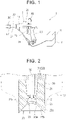
- FIG. 1 schematically shows an electrostatic coating device 1 including an electrostatic coating handgun 3 according to an embodiment.
- the electrostatic coating device 1 is an electrostatic atomization type coating device that electrostatically atomizes paint PI (see FIG. 4 ).
- the electrostatic coating device 1 includes the electrostatic coating handgun 3, a high voltage controller 5, an air motor controller 7, an air supply device (not shown), and a paint supply device (not shown).
- the electrostatic coating handgun 3 is a device that sprays electrically charged atomized paint PI onto a workpiece (object to be coated) W (see FIG. 4 ) by a manual operation by an operator holding the electrostatic coating handgun 3.
- the electrostatic coating handgun 3 is connected to the high voltage controller 5 and the air motor controller 7.
- the air supply device supplies high pressure air to the electrostatic coating handgun 3.
- the high pressure air serves as a rotational driving source for a rotating head 20 of the electrostatic coating handgun 3.
- the paint supply device supplies the water-based paint PI for electrostatic atomization coating to the electrostatic coating handgun 3.
- the paint PI is, for example, paint made of a resin containing water.
- the electrostatic coating handgun 3 includes the rotating head 20, an air motor 30, a high voltage generator 40, and a housing 10.
- the housing 10 supports or houses the rotating head 20, the air motor 30, and the high voltage generator 40.
- the housing 10 has a body portion 11, a grip portion 13 to be held by the operator, a trigger 15, and a cap 17.
- the body portion 11 is made of an electrically insulating material such as electrically insulating resin.
- the rotating head 20 is supported by a tip end of the body portion 11 with a tip end of the rotating head 20 exposed.
- the air motor 30 is housed behind (on the base end side of) the rotating head 20 in the body portion 11.
- the high voltage generator 40 is housed near the grip portion 13 in the body portion 11.
- the grip portion 13 is made of an electrically conductive material such as electrically conductive resin and is grounded by a ground wire (not shown), so that electric charge will not accumulate on the operator's body even when the operator holds the grip portion 13.
- the trigger 15 opens a trigger valve (not shown) to supply the paint PI supplied from the paint supply device to the body portion 11 through a paint supply hose 19 to the rotating head 20 through a paint supply pipe 50 that will be described later.
- the cap 17 is attached to the tip end of the body portion 11. The cap 17 covers the outer peripheral surface of the rotating head 20 except the tip end of the rotating head 20 and also covers a part of the air motor 30.
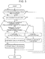
- FIG. 2 is a schematic sectional view of the rotating head 20.
- the rotating head 20 has, in its tip end (grooved portion 29), grooves 27 (see FIG. 3 ) for emitting the paint P1.
- the rotating head 20 emits the supplied liquid paint PI by centrifugal force generated by rotation of the rotating head 20.
- the rotating head 20 has a generally cylindrical shape, and includes an attachment portion 21 in the base end side (rear side) of the rotating head 20 and a head portion 23 in the tip end side (front side) of the rotating head 20.
- the diameter of the rotating head 20 is, for example, 20 to 50 mm.
- the attachment portion 21 is fitted on a rotating shaft 31 of the air motor 30.
- the rotating shaft 31 of the air motor 30 is a hollow shaft, and the paint supply pipe 50 for supplying the paint PI to the head portion 23 is located inside the rotating shaft 31.
- the head portion 23 has a first inner peripheral surface 23a, a second inner peripheral surface 23b, and an outer peripheral surface 23c.
- the first inner peripheral surface 23a is shaped like a tapered surface of a truncated cone, and the diameter of the first inner peripheral surface 23a increases as it gets closer to the tip end of the head portion 23.
- the second inner peripheral surface 23b extends from the tip end of the first inner peripheral surface 23a and is also shaped like a tapered surface of a truncated cone. The diameter of the second inner peripheral surface 23b increases at a higher rate than the diameter of the first inner peripheral surface 23a as it gets closer to the tip end of the head portion 23.
- the outer peripheral surface 23c has a generally cylindrical surface.
- a hub 25 is provided radially inside the first inner peripheral surface 23a, and a paint space S is defined by the first inner peripheral surface 23a and the hub 25.
- a tip end of the paint supply pipe 50 faces the paint space S.
- the hub 25 has, in its outer edge portion, an outlet hole 25a through which the paint PI flows out of the paint space S.
- the second inner peripheral surface 23b functions as a diffusion surface by which the paint PI having flowed out of the paint space S through the outlet hole 25a is diffused by centrifugal force.
- the second inner peripheral surface 23b has the grooved portion 29 in its tip end.
- the grooved portion 29 has the grooves 27.
- FIG. 3 is a schematic perspective view of the tip end of the rotating head 20.
- the grooves 27 are provided in order to emit the paint PI in the form of filaments. Specifically, the grooves 27 extend in the axial direction to the tip end (front end) of the rotating head 20 and are tilted radially outward along the second inner peripheral surface 23b.
- the grooves 27 (e.g., 600 to 1200 grooves) are provided in the circumferential direction.
- Each groove 27 has a V-shaped (triangular) cross section. The cross section of each groove 27 appears on the outer peripheral surface 23c.
- the tip end of the rotating head 20 therefore has a jagged edge as viewed from the outer peripheral surface 23c side.
- the air motor 30 is located behind the rotating head 20 in the body portion 11 of the housing 10 and the rotating shaft 31 of the air motor 30 is connected to the rotating head 20, so that the air motor 30 applies rotational power to the rotating head 20 using high-pressure air supplied from the air supply device.
- the air motor 30 is relatively small in order to reduce the burden on the operator.
- the air motor controller 7 controls the rotational speed of the air motor 30.
- a brake mechanism 37 is provided around the air motor 30. The brake mechanism 37 stops the rotation of the air motor 30 by holding the rotating shaft 31.
- the high voltage generator 40 is a device that applies a voltage to the paint P1.
- the high voltage generator 40 negatively charges the rotating head 20 by generating a negative high voltage and applying it to the rotating head 20.
- a strong electrostatic field is thus formed between the rotating head 20 serving as a negative electrode and the grounded workpiece W serving as a positive electrode.
- FIG. 4 schematically illustrates an electrostatic field formed between the rotating head 20 and the workpiece W.
- FIG. 4 merely illustrates the electrostatic field and does not accurately show the shape of the electrostatic coating handgun 3 and the arrangement of the main functional parts in the electrostatic coating handgun 3.
- the paint PI emitted in the form of filaments from the rotating head 20 is electrostatically atomized as it breaks up into droplets by the electrostatic force of the electrostatic field formed between the rotating head 20 and the workpiece W.
- the paint PI thus electrostatically atomized is attracted and adheres to the grounded workpiece W due to the negative charge of the paint P1.
- a coating film P2 is formed on the surface of the workpiece W.
- the paint PI is electrostatically atomized by the electrostatic force in the electrostatic field formed between the rotating head 20 and the workpiece W without using shaping air. Accordingly, the coating efficiency is improved as the paint particles adhering to the workpiece W and the paint particles floating near the workpiece W are not lifted by the airflow accompanying the shaping air. Moreover, generating ionic wind from the tip end of the rotating head 20 by glow discharge can assist stable flight and pattern formation of the atomized paint P1.
- the high voltage generator 40 is relatively small, and as shown in FIG. 1 , is located near the grip portion 13, namely away from the rotating head 20 and the air motor 30 that need to be disposed in the tip end of the electrostatic coating handgun 3.
- the electrostatic coating handgun 3 has such a balanced center of gravity that the operator holding the grip portion 13 is less likely to feel the weight.
- the electrostatic coating handgun 3 thus has a structure that does not impose a burden on the operator.
- the high voltage generator 40 is placed near the grip portion 13 so as to be away from the tip end of the electrostatic coating handgun 3, electrical insulation can be provided while allowing efficient voltage application to the paint P1.
- the high voltage controller (voltage control device) 5 controls the output voltage of the high voltage generator 40 to adjust the strength of the electrostatic field in order to control the particle size of the paint PI to be electrostatically atomized to the particle size suitable for coating or to reduce variation in particle size of the paint PI to be electrostatically atomized. For example, when the high voltage controller 5 increases the output voltage of the high voltage generator 40 to increase the strength of the electrostatic field, the electrostatic force is increased and the particle size of the paint PI to be electrostatically atomized is therefore reduced.
- the particle size suitable for coating is preferably 20 to 30 ⁇ m in Sauter mean diameter (SMD).
- the coating pattern (coating area) can also be controlled by adjusting the strength of the electrostatic field by the high voltage controller 5. For example, when the strength of the electrostatic field is increased by the high voltage controller 5, the electrostatically atomized paint PI is driven more straight, and the coating pattern therefore becomes narrow. On the other hand, when the strength of the electrostatic field is decreased by the high voltage controller 5, the electrostatically atomized paint P1 is driven less straight, and the coating pattern therefore becomes wide.
- the high voltage controller 5 controls the output voltage of the high voltage generator 40 so that the potential at the open end of the rotating head 20 is always constant, the potential difference V would be fixed.
- the electric field strength E therefore would change according to a change in distance between the workpiece W and the rotating head 20.
- the particle size of the paint PI to be electrostatically atomized would vary. Accordingly, the electrostatic atomization of the paint PI would become unstable and the coating efficiency also would become unstable.
- the high voltage controller 5 reduces the output voltage of the high voltage generator 40.
- Fluctuations in electric field strength E are thus reduced, and as a result, variation in particle size of the paint PI to be electrostatically atomized is reduced. Accordingly, the electrostatic atomization of the paint PI can be stabilized, and the coating efficiency can also be stabilized.
- the air motor controller (motor control device) 7 is connected to the electrostatic coating handgun 3, and controls the rotational speed of the air motor 30 as described above.
- the air motor controller 7 is electrically connected to the high voltage controller 5, and sends and receives information to and from the high voltage controller 5.
- the electrostatic coating device 1 When coating the workpiece W using the electrostatic coating device 1 configured as described above, the electrostatic coating device 1 is first started to rotate the rotating head 20 at high speed and to apply a negative high voltage to the rotating head 20. A static electric field is thus formed between the rotating head 20 and the workpiece W. Next, the operator pulls the trigger 15. The trigger valve thus opens, so that the paint PI supplied from the paint supply device to the body portion 11 through the paint supply hose 19 is supplied to the rotating head 20 through the paint supply pipe 50.
- the paint PI supplied to the rotating head 20 is subjected to the centrifugal force and is emitted in the form of filaments in the direction of the centrifugal force from the grooved portion 29 (plurality of grooves 27) formed on the tip end of the second inner peripheral surface 23b of the rotating head 20.
- the paint P1 emitted in the form of filaments is electrostatically atomized as it breaks up into droplets by the electrostatic force of the electrostatic field formed between the rotating head 20 and the workpiece W.
- the electrostatically atomized paint P1 is attracted and adheres to the grounded workpiece W due to the negative charge of the paint P1.
- the coating film P2 is thus formed on the surface of the workpiece W.
- Typical electrostatic coating handguns that are used for electrostatic spray coating by an operator are of the type that does not use a rotating head.
- a protective cover is sometimes provided outside a head portion in order to prevent the head portion rotating at high speed during electrostatic coating from coming into contact with an operator etc.
- the paint scatters toward the protective cover when an increased voltage is applied to the paint in order to improve the coating efficiency. This may end up reducing the coating efficiency.
- the tip end of the rotating head 20 is machined to be sharp in order to atomize the paint PI (the tip end of the rotating head 20 has a jagged edge as viewed from the outer peripheral surface 23c side) as shown in FIG. 3 , some safety measures are required as the operator may have a cut etc. if he or she touches the rotating head 20 rotating at high speed.
- the output voltage of the high voltage generator 40 and the rotational speed of the rotating head 20 are controlled according to the distance between the operator or the workpiece W and the rotating head 20.
- the air motor controller 7 reduces the rotational speed of the air motor 30 when the current value discharged from the rotating head 20 increases due to the movement of the electrostatic coating handgun 3 (rotating head 20) caused by an operation by the operator.
- the high voltage controller 5 controls the output voltage of the high voltage generator 40 to zero and the air motor controller 7 stops the rotation of the air motor 30 when the amount of change (amount of increase) per unit time in current value discharged from the rotating head 20 is larger than a predetermined amount of change (predetermined amount of increase) or when the absolute value of the current value discharged from the rotating head 20 is larger than a predetermined value.
- the air motor controller 7 uses the brake mechanism 37 provided around the air motor 30 when stopping the rotation of the air motor 30.
- the brake mechanism 37 that stops the rotation of the air motor 30 by holding the rotating shaft 31 is implemented by, for example, pressing a pneumatically or hydraulically driven brake pad etc. against the rotating head 20 or the rotating shaft 31 of the air motor 30.
- the current value discharged from the rotating head 20 (current value flowing from the high voltage generator 40) varies according to the spatial resistance value between the workpiece W located in front of the rotating head 20, the operator, etc. and the rotating head 20.
- Such a spatial resistance value becomes smaller as the distance between the workpiece W, the operator, etc. and the rotating head 20 decreases (becomes shorter).
- the high voltage controller 5 when the current value discharged from the rotating head 20 increases due to the movement of the rotating head 20 caused by an operation by the operator (due to the rotating head 20 approaching the workpiece W or the operator), the high voltage controller 5 sends a command to reduce the output voltage of the high voltage generator 40 in order to make this current value constant.
- information indicating that the current value has increased is transmitted from the high voltage controller 5 to the air motor controller 7, and in response to this information, the air motor controller 7 sends a command to reduce the rotational speed of the air motor 30. This reduces the possibility that the rotating head 20 rotating at high speed may contact the workpiece W, the operator, etc. Safety during electrostatic coating is thus ensured even in the electrostatic coating handgun 3 of the type that does not use shaping air, namely in the electrostatic coating handgun 3 in which it is difficult to provide a protective cover outside the rotating head 20.
- the high voltage controller 5 sends a command to control the output voltage of the high voltage generator 40 to zero and the air motor controller 7 sends a command to stop the rotation of the air motor 30. This can prevent the operator from getting an electric shock, a cut, etc. Safety during electrostatic coating is thus ensured to a greater extent.
- the air motor controller 7 sends a command to operate the brake mechanism 37, so that the air motor 30 can be stopped more quickly and more reliably. Safety is thus more reliably ensured.
- the protective cover provided outside the rotating head 20 is omitted. This configuration improves the coating efficiency and also reduces the possibility that the rotating head 20 rotating at high speed may contact the workpiece W, the operator, etc. and thus ensures safety during electrostatic coating.
- step S1 it is determined in step S1 whether the electrostatic coating device 1 has been started. In other words, it is determined in step S1 whether the rotating head 20 is rotating at high speed and whether a negative high voltage is being applied to the rotating head 20.
- the routine ends when the determination result of step S1 is NO. On the other hand, when the determination result of step S 1 is YES, it is necessary to take safety measures. The routine therefore proceeds to step S2.
- step S2 the high voltage controller 5 determines whether the current value emitted from the open end of the rotating head 20 has risen (increased), in other words, whether the rotating head 20 has approached the workpiece W or the operator.
- the routine ends without changing the output voltage of the high voltage generator 40 and the rotational speed of the air motor 30 by the high voltage controller 5 and the air motor controller 7.
- the routine proceeds to step S3.
- step S3 the high voltage controller 5 determines whether the amount of change in current value discharged from the rotating head 20 is larger than the predetermined amount of change or the absolute value of the current value discharged from the rotating head 20 is larger than the predetermined value.
- the determination result of step S3 is YES, in other words, when the rotating head 20 has rapidly approached the workpiece W, the operator, etc. or when the distance between the workpiece W, the worker, etc. and the rotating head 20 is extremely short, the routine proceeds to step S4.
- step S4 the high voltage controller 5 sends a command to control the output voltage of the high voltage generator 40 to zero, and the routine then proceeds to step S5.
- the air motor controller 7 sends a command to stop the rotation of the air motor 30 in step S5 and operates the brake mechanism 37 in step S6. The routine then ends.
- step S3 determines whether the rotating head 20 has approached the workpiece W, the operator, etc. but not rapidly, and the distance between the workpiece W, the operator, etc. and the rotating head 20 is not extremely short.
- step S7 the high voltage controller 5 sends a command to reduce the output voltage of the high voltage generator 40.
- the routine then proceeds to step S8.
- step S8 the air motor controller 7 sends a command to rotate the air motor 30 at low speed. The routine then ends.
- the paint PI is a water-based paint.
- the present invention is not limited to this, and the paint PI may be an oil-based paint (solvent-based paint).
- the present invention is applied to the electrostatic coating handgun 3 of the type that does not use shaping air.
- the present invention is not limited to this, and the present invention may be applied to, for example, an electrostatic coating handgun of the type that uses shaping air.
- the present invention is applied to the electrostatic atomization type electrostatic coating device 1.
- the present invention is not limited to this, and the present invention may be applied to an electrostatic coating device of the type (air atomization type or airless atomization type) that atomizes paint by injecting the paint from a handgun with a mechanical force (e.g., compressed air or high pressure applied to the paint) and electrically charges the atomized paint.
- a mechanical force e.g., compressed air or high pressure applied to the paint
- the electrostatic coating handgun 3 is connected to the high voltage controller 5 and the air motor controller 7 that are provided outside the electrostatic coating handgun 3.
- the present invention is not limited to this.
- either or both of the high voltage controller 5 and the air motor controller 7 may be provided inside the electrostatic coating handgun 3, or the output voltage of the high voltage generator and the rotational speed of the motor may be controlled remotely.
- the grip portion 13 to be held by the operator is integral with the housing 10.
- the present invention is not limited to this, and the grip portion 13 may be a separate member from the housing 10.
- the present invention both improvement in coating efficiency and safety can be achieved.
- the present invention is therefore extremely useful when applied to electrostatic coating handguns and electrostatic coating methods.
Landscapes
- Electrostatic Spraying Apparatus (AREA)
- Application Of Or Painting With Fluid Materials (AREA)
Abstract
Description
- The present invention relates to electrostatic coating handguns and electrostatic coating methods for spraying electrically charged atomized paint onto an object to be coated.
- In recent years, electrostatic spray coating that provides high coating quality has been automated by robots, but electrostatic spray coating by operators using an electrostatic coating spray gun (electrostatic coating handgun) is still widely used.
- Such electrostatic coating handguns that are used for electrostatic spray coating by operators are typically of the type that does not use a rotating head called a bell. However, there are also electrostatic coating handguns of the type that use a rotating head. For example,
Japanese Unexamined Patent Application Publication No. 9-070557 JP 9-070557 A - According to the above
JP 9-070557 A - In electrostatic coating handguns that spray electrically charged atomized paint onto an object to be coated, an increased voltage tends to be applied to the paint in order to improve the coating efficiency. In the case where electrostatic coating handguns have such a protective cover outside the rotating head as in
JP 9-070557 A - In the electrostatic coating handgun of
JP 9-070557 A - The present invention provides a technique that achieve both improvement in coating efficiency and safety in an electrostatic coating handgun and an electrostatic coating method.
- In an electrostatic coating handgun and an electrostatic coating method according to the present invention, an output voltage of a high voltage generator and a rotational speed of a rotating head are controlled according to the distance between an operator etc. and the rotating head.
- Specifically, the present invention relates to an electrostatic coating handgun that sprays electrically charged atomized paint onto an object to be coated.
- This electrostatic coating handgun includes: a rotating head having on a tip end of the rotating head a groove through which the paint is discharged; a motor configured to apply rotational power to the rotating head; a high voltage generator configured to apply a voltage to the paint; a housing supporting the rotating head with the tip end of the rotating head being exposed, and housing the motor and the high voltage generator; and a grip portion to be held by an operator; a voltage control device configured to reduce an output voltage of the high voltage generator when a current value discharged from the rotating head increases due to movement of the rotating head caused by an operation by the operator; and a motor control device configured to reduce a rotational speed of the motor when the current value discharged from the rotating head increases due to the movement of the rotating head caused by the operation by the operator.
- According to this configuration, the rotating head having on the tip end of the rotating head the groove through which the paint is discharged is supported by the housing with the tip end of the rotating head being exposed. Accordingly, the discharged paint is more likely to be directed toward the object to be coated without scattering, as compared to the case where a protective cover etc. that covers the rotating head is provided. The coating efficiency is therefore improved.
- When the voltage of the high voltage generator is approximately constant, the value of the current discharged from the rotating head (current flowing from the high voltage generator) varies according to a spatial resistance value between the object to be coated that is located in front of the rotating head, the operator, etc. and the rotating head. It is known that the spatial resistance value becomes smaller as the distance between the object to be coated, the operator, etc. and the rotating head decreases.
- Therefore, according to this configuration, the voltage control device reduces the output voltage of the high voltage generator when the current discharged from the rotating head increases due to the movement of the rotating head (due to the rotating head approaching the object to be coated or the operator) caused by the operation by the operator. In this case, the motor control device reduces the rotational speed of the motor in response to the increase in current discharged from the rotating head. This configuration reduces the possibility that the rotating head rotating at high speed may contact the object to be coated, the operator, etc. Safety is thus ensured.
- According to the electrostatic coating handgun of the present invention, both improvement in coating efficiency and safety can be achieved.
- In the above electrostatic coating handgun, the voltage control device may be configured to control the output voltage of the high voltage generator to zero when an amount of change per unit time in the current value discharged from the rotating head is larger than a predetermined amount of change or when an absolute value of the current value is larger than a predetermined value, and the motor control device may be configured to stop rotation of the motor when the amount of change per unit time in the current value discharged from the rotating head is larger than the predetermined amount of change or when the absolute value of the current value is larger than the predetermined value.
- According to this configuration, in a more urgent situation than a situation where the rotating head normally approaches the object to be coated, the operator, etc., specifically, when the amount of change per unit time in the current value is large (when the rotating head has rapidly approached the object to be coated, the operator, etc.) or when the absolute value of the current value is large (when the distance between the object to be coated, the operator, etc. and the rotating head is extremely short), the output voltage of the high voltage generator is controlled to zero and the rotation of the motor is stopped. This can prevent the operator from getting an electric shock, a cut, etc. Safety during electrostatic coating is thus ensured to a greater extent.
- In the above electrostatic coating handgun, the motor control device may configured to use a brake mechanism when stopping the rotation of the motor.
- According to this configuration, even when it is difficult to deal with a sudden decrease in the rotational speed of the motor by merely sending an output stop command to the motor, the rotation of the motor can be stopped more quickly and more reliably by using the brake mechanism. Safety is thus more reliably ensured.
- The electrostatic coating handgun may be configured to electrostatically atomize the paint without using shaping air.
- When atomizing the paint with shaping air, there is air moving from a base end side (rear side) toward a tip end side (front side). In this case, even if the rotating head is provided with a protective cover, a decrease in coating efficiency would be small. As described above, in the electrostatic coating handgun of the present invention, both safety and improvement in coating efficiency can be achieved without using such a protective cover. Accordingly, the present invention is suitably used for an electrostatic atomization type handgun that electrostatically atomizes paint without using shaping air.
- The present invention also relates to an electrostatic coating method in which electrically charged atomized paint is sprayed onto an object to be coated.
- In this electrostatic coating method, an electrostatic coating handgun is prepared. The electrostatic coating handgun includes: a rotating head having on a tip end of the rotating head a groove through which the paint is discharged; a motor configured to apply rotational power to the rotating head; a high voltage generator configured to apply a voltage to the paint; a housing supporting the rotating head with the tip end of the rotating head being exposed, and housing the motor and the high voltage generator; and a grip portion to be held by an operator.
- In this electrostatic coating method, an output voltage of the high voltage generator and a rotational speed of the motor are reduced when a current value discharged from the rotating head increases due to movement of the rotating head caused by an operation by the operator when the operator sprays the paint onto the object to be coated by using the electrostatic coating handgun.
- According to this configuration, the output voltage of the high voltage generator and the rotational speed of the motor are reduced when the current discharged from the rotating head increases due to, for example, the rotating head approaching the object to be coated or the operator). This configuration reduces the possibility that the rotating head rotating at high speed may contact the object to be coated, the operator, etc. Safety is thus ensured.
- As described above, according to the electrostatic coating handgun and the electrostatic coating method according to the present invention, both improvement in coating efficiency and safety can be achieved.
- Features, advantages, and technical and industrial significance of exemplary embodiments of the invention will be described below with reference to the accompanying drawings, in which like signs denote like elements, and wherein:
-
FIG. 1 schematically shows an electrostatic coating device including an electrostatic coating handgun according to an embodiment of the present invention; -
FIG. 2 is a schematic sectional view of a rotating head; -
FIG. 3 is a schematic perspective view of a tip end of the rotating head; -
FIG. 4 schematically illustrates an electrostatic field formed between the rotating head and an object to be coated; and -
FIG. 5 is a flowchart showing an example of safety control that is performed by the electrostatic coating device. - A mode for carrying out the invention will be described below with reference to the drawings.
-
FIG. 1 schematically shows anelectrostatic coating device 1 including anelectrostatic coating handgun 3 according to an embodiment. Theelectrostatic coating device 1 is an electrostatic atomization type coating device that electrostatically atomizes paint PI (seeFIG. 4 ). As shown inFIG. 1 , theelectrostatic coating device 1 includes theelectrostatic coating handgun 3, ahigh voltage controller 5, anair motor controller 7, an air supply device (not shown), and a paint supply device (not shown). - The
electrostatic coating handgun 3 is a device that sprays electrically charged atomized paint PI onto a workpiece (object to be coated) W (seeFIG. 4 ) by a manual operation by an operator holding theelectrostatic coating handgun 3. Theelectrostatic coating handgun 3 is connected to thehigh voltage controller 5 and theair motor controller 7. The air supply device supplies high pressure air to theelectrostatic coating handgun 3. The high pressure air serves as a rotational driving source for arotating head 20 of theelectrostatic coating handgun 3. The paint supply device supplies the water-based paint PI for electrostatic atomization coating to theelectrostatic coating handgun 3. The paint PI is, for example, paint made of a resin containing water. - As shown in
FIG. 1 , theelectrostatic coating handgun 3 includes the rotatinghead 20, anair motor 30, ahigh voltage generator 40, and ahousing 10. Thehousing 10 supports or houses the rotatinghead 20, theair motor 30, and thehigh voltage generator 40. - The
housing 10 has abody portion 11, agrip portion 13 to be held by the operator, atrigger 15, and acap 17. Thebody portion 11 is made of an electrically insulating material such as electrically insulating resin. The rotatinghead 20 is supported by a tip end of thebody portion 11 with a tip end of the rotatinghead 20 exposed. Theair motor 30 is housed behind (on the base end side of) the rotatinghead 20 in thebody portion 11. Thehigh voltage generator 40 is housed near thegrip portion 13 in thebody portion 11. Thegrip portion 13 is made of an electrically conductive material such as electrically conductive resin and is grounded by a ground wire (not shown), so that electric charge will not accumulate on the operator's body even when the operator holds thegrip portion 13. When the operator holding thegrip portion 13 pulls thetrigger 15, thetrigger 15 opens a trigger valve (not shown) to supply the paint PI supplied from the paint supply device to thebody portion 11 through apaint supply hose 19 to the rotatinghead 20 through apaint supply pipe 50 that will be described later. Thecap 17 is attached to the tip end of thebody portion 11. Thecap 17 covers the outer peripheral surface of the rotatinghead 20 except the tip end of the rotatinghead 20 and also covers a part of theair motor 30. -
FIG. 2 is a schematic sectional view of the rotatinghead 20. The rotatinghead 20 has, in its tip end (grooved portion 29), grooves 27 (seeFIG. 3 ) for emitting the paint P1. The rotatinghead 20 emits the supplied liquid paint PI by centrifugal force generated by rotation of the rotatinghead 20. As shown inFIG. 2 , the rotatinghead 20 has a generally cylindrical shape, and includes anattachment portion 21 in the base end side (rear side) of the rotatinghead 20 and ahead portion 23 in the tip end side (front side) of the rotatinghead 20. The diameter of the rotatinghead 20 is, for example, 20 to 50 mm. Theattachment portion 21 is fitted on arotating shaft 31 of theair motor 30. The rotatingshaft 31 of theair motor 30 is a hollow shaft, and thepaint supply pipe 50 for supplying the paint PI to thehead portion 23 is located inside the rotatingshaft 31. - The
head portion 23 has a first innerperipheral surface 23a, a second innerperipheral surface 23b, and an outerperipheral surface 23c. The first innerperipheral surface 23a is shaped like a tapered surface of a truncated cone, and the diameter of the first innerperipheral surface 23a increases as it gets closer to the tip end of thehead portion 23. The second innerperipheral surface 23b extends from the tip end of the first innerperipheral surface 23a and is also shaped like a tapered surface of a truncated cone. The diameter of the second innerperipheral surface 23b increases at a higher rate than the diameter of the first innerperipheral surface 23a as it gets closer to the tip end of thehead portion 23. The outerperipheral surface 23c has a generally cylindrical surface. Ahub 25 is provided radially inside the first innerperipheral surface 23a, and a paint space S is defined by the first innerperipheral surface 23a and thehub 25. A tip end of thepaint supply pipe 50 faces the paint space S. Thehub 25 has, in its outer edge portion, anoutlet hole 25a through which the paint PI flows out of the paint space S. The second innerperipheral surface 23b functions as a diffusion surface by which the paint PI having flowed out of the paint space S through theoutlet hole 25a is diffused by centrifugal force. The second innerperipheral surface 23b has the groovedportion 29 in its tip end. The groovedportion 29 has thegrooves 27. -
FIG. 3 is a schematic perspective view of the tip end of the rotatinghead 20. Thegrooves 27 are provided in order to emit the paint PI in the form of filaments. Specifically, thegrooves 27 extend in the axial direction to the tip end (front end) of the rotatinghead 20 and are tilted radially outward along the second innerperipheral surface 23b. The grooves 27 (e.g., 600 to 1200 grooves) are provided in the circumferential direction. Eachgroove 27 has a V-shaped (triangular) cross section. The cross section of eachgroove 27 appears on the outerperipheral surface 23c. The tip end of the rotatinghead 20 therefore has a jagged edge as viewed from the outerperipheral surface 23c side. - As described above, the
air motor 30 is located behind the rotatinghead 20 in thebody portion 11 of thehousing 10 and therotating shaft 31 of theair motor 30 is connected to the rotatinghead 20, so that theair motor 30 applies rotational power to the rotatinghead 20 using high-pressure air supplied from the air supply device. Theair motor 30 is relatively small in order to reduce the burden on the operator. Theair motor controller 7 controls the rotational speed of theair motor 30. As shown inFIG. 1 , abrake mechanism 37 is provided around theair motor 30. Thebrake mechanism 37 stops the rotation of theair motor 30 by holding the rotatingshaft 31. - The
high voltage generator 40 is a device that applies a voltage to the paint P1. Thehigh voltage generator 40 negatively charges the rotatinghead 20 by generating a negative high voltage and applying it to the rotatinghead 20. A strong electrostatic field is thus formed between the rotatinghead 20 serving as a negative electrode and the grounded workpiece W serving as a positive electrode. -
FIG. 4 schematically illustrates an electrostatic field formed between the rotatinghead 20 and the workpiece W.FIG. 4 merely illustrates the electrostatic field and does not accurately show the shape of theelectrostatic coating handgun 3 and the arrangement of the main functional parts in theelectrostatic coating handgun 3. The paint PI emitted in the form of filaments from the rotatinghead 20 is electrostatically atomized as it breaks up into droplets by the electrostatic force of the electrostatic field formed between the rotatinghead 20 and the workpiece W. As shown inFIG. 4 , the paint PI thus electrostatically atomized is attracted and adheres to the grounded workpiece W due to the negative charge of the paint P1. As a result, a coating film P2 is formed on the surface of the workpiece W. - As described above, in the present embodiment, the paint PI is electrostatically atomized by the electrostatic force in the electrostatic field formed between the rotating
head 20 and the workpiece W without using shaping air. Accordingly, the coating efficiency is improved as the paint particles adhering to the workpiece W and the paint particles floating near the workpiece W are not lifted by the airflow accompanying the shaping air. Moreover, generating ionic wind from the tip end of the rotatinghead 20 by glow discharge can assist stable flight and pattern formation of the atomized paint P1. - The
high voltage generator 40 is relatively small, and as shown inFIG. 1 , is located near thegrip portion 13, namely away from the rotatinghead 20 and theair motor 30 that need to be disposed in the tip end of theelectrostatic coating handgun 3. Theelectrostatic coating handgun 3 has such a balanced center of gravity that the operator holding thegrip portion 13 is less likely to feel the weight. Theelectrostatic coating handgun 3 thus has a structure that does not impose a burden on the operator. Moreover, since thehigh voltage generator 40 is placed near thegrip portion 13 so as to be away from the tip end of theelectrostatic coating handgun 3, electrical insulation can be provided while allowing efficient voltage application to the paint P1. - The high voltage controller (voltage control device) 5 controls the output voltage of the
high voltage generator 40 to adjust the strength of the electrostatic field in order to control the particle size of the paint PI to be electrostatically atomized to the particle size suitable for coating or to reduce variation in particle size of the paint PI to be electrostatically atomized. For example, when thehigh voltage controller 5 increases the output voltage of thehigh voltage generator 40 to increase the strength of the electrostatic field, the electrostatic force is increased and the particle size of the paint PI to be electrostatically atomized is therefore reduced. On the other hand, when thehigh voltage controller 5 reduces the output voltage of thehigh voltage generator 40 to reduce the strength of the electrostatic field, the electrostatic force is reduced and the particle size of the paint PI to be electrostatically atomized is therefore increased. For example, the particle size suitable for coating is preferably 20 to 30 µm in Sauter mean diameter (SMD). - The coating pattern (coating area) can also be controlled by adjusting the strength of the electrostatic field by the
high voltage controller 5. For example, when the strength of the electrostatic field is increased by thehigh voltage controller 5, the electrostatically atomized paint PI is driven more straight, and the coating pattern therefore becomes narrow. On the other hand, when the strength of the electrostatic field is decreased by thehigh voltage controller 5, the electrostatically atomized paint P1 is driven less straight, and the coating pattern therefore becomes wide. - If the
high voltage controller 5 controls the output voltage of thehigh voltage generator 40 so that the potential at the open end of the rotatinghead 20 is always constant, the potential difference V would be fixed. The electric field strength E therefore would change according to a change in distance between the workpiece W and the rotatinghead 20. As a result, the particle size of the paint PI to be electrostatically atomized would vary. Accordingly, the electrostatic atomization of the paint PI would become unstable and the coating efficiency also would become unstable. - In the present embodiment, the
high voltage controller 5 controls the output voltage of thehigh voltage generator 40 so that the current (discharge current) discharged from the open end of the rotatinghead 20 is always constant. Since the potential difference V is changed according to a change in distance between the workpiece W and the rotatinghead 20, fluctuations in electric field strength E are reduced. Specifically, as the distance between the workpiece W and the rotatinghead 20 increases, a resistance component R (spatial resistance value) for the discharge current I increases. Thehigh voltage controller 5 therefore controls thehigh voltage generator 40 so that the output voltage of thehigh voltage generator 40 increases (the potential difference V (= R × I) increases) as the distance between the workpiece W and the rotatinghead 20 increases. - On the other hand, as the distance between the workpiece W and the rotating
head 20 decreases, the resistance component R (spatial resistance value) for the discharge current I decreases. Thehigh voltage controller 5 therefore controls thehigh voltage generator 40 so that the output voltage of thehigh voltage generator 40 decreases (the potential difference V (= R × I) decreases) as the distance between the workpiece W and the rotatinghead 20 decreases. In other words, when the current value that is discharged from the rotatinghead 20 increases due to the movement of the electrostatic coating handgun 3 (rotating head 20) caused by an operation by the operator, thehigh voltage controller 5 reduces the output voltage of thehigh voltage generator 40. - Fluctuations in electric field strength E are thus reduced, and as a result, variation in particle size of the paint PI to be electrostatically atomized is reduced. Accordingly, the electrostatic atomization of the paint PI can be stabilized, and the coating efficiency can also be stabilized.
- The air motor controller (motor control device) 7 is connected to the
electrostatic coating handgun 3, and controls the rotational speed of theair motor 30 as described above. Theair motor controller 7 is electrically connected to thehigh voltage controller 5, and sends and receives information to and from thehigh voltage controller 5. - When coating the workpiece W using the
electrostatic coating device 1 configured as described above, theelectrostatic coating device 1 is first started to rotate the rotatinghead 20 at high speed and to apply a negative high voltage to the rotatinghead 20. A static electric field is thus formed between the rotatinghead 20 and the workpiece W. Next, the operator pulls thetrigger 15. The trigger valve thus opens, so that the paint PI supplied from the paint supply device to thebody portion 11 through thepaint supply hose 19 is supplied to the rotatinghead 20 through thepaint supply pipe 50. - The paint PI supplied to the rotating
head 20 is subjected to the centrifugal force and is emitted in the form of filaments in the direction of the centrifugal force from the grooved portion 29 (plurality of grooves 27) formed on the tip end of the second innerperipheral surface 23b of the rotatinghead 20. The paint P1 emitted in the form of filaments is electrostatically atomized as it breaks up into droplets by the electrostatic force of the electrostatic field formed between the rotatinghead 20 and the workpiece W. The electrostatically atomized paint P1 is attracted and adheres to the grounded workpiece W due to the negative charge of the paint P1. The coating film P2 is thus formed on the surface of the workpiece W. - Typical electrostatic coating handguns that are used for electrostatic spray coating by an operator are of the type that does not use a rotating head. However, in electrostatic coating handguns of the type that uses a rotating head like the present embodiment, a protective cover is sometimes provided outside a head portion in order to prevent the head portion rotating at high speed during electrostatic coating from coming into contact with an operator etc.
- In the case where electrostatic coating handguns have such a protective cover outside the rotating head, the paint scatters toward the protective cover when an increased voltage is applied to the paint in order to improve the coating efficiency. This may end up reducing the coating efficiency.
- In particular, in the
electrostatic coating handgun 3 of the type that does not use shaping air as in the present embodiment, it is difficult to provide a protective cover outside the rotatinghead 20. Since there is no air moving from the base end side (rear side) toward the tip end side (front side), coating would not be properly performed as the paint PI emitted from the tip end of the rotatinghead 20 would scatter in a direction tangential to the rotation of the rotatinghead 20 and would adhere to the protective cover. - However, since the tip end of the rotating
head 20 is machined to be sharp in order to atomize the paint PI (the tip end of the rotatinghead 20 has a jagged edge as viewed from the outerperipheral surface 23c side) as shown inFIG. 3 , some safety measures are required as the operator may have a cut etc. if he or she touches the rotatinghead 20 rotating at high speed. - In the
electrostatic coating handgun 3 of the present embodiment, the output voltage of thehigh voltage generator 40 and the rotational speed of the rotatinghead 20 are controlled according to the distance between the operator or the workpiece W and the rotatinghead 20. Specifically, theair motor controller 7 reduces the rotational speed of theair motor 30 when the current value discharged from the rotatinghead 20 increases due to the movement of the electrostatic coating handgun 3 (rotating head 20) caused by an operation by the operator. Moreover, thehigh voltage controller 5 controls the output voltage of thehigh voltage generator 40 to zero and theair motor controller 7 stops the rotation of theair motor 30 when the amount of change (amount of increase) per unit time in current value discharged from the rotatinghead 20 is larger than a predetermined amount of change (predetermined amount of increase) or when the absolute value of the current value discharged from the rotatinghead 20 is larger than a predetermined value. - Moreover, the
air motor controller 7 uses thebrake mechanism 37 provided around theair motor 30 when stopping the rotation of theair motor 30. Thebrake mechanism 37 that stops the rotation of theair motor 30 by holding the rotatingshaft 31 is implemented by, for example, pressing a pneumatically or hydraulically driven brake pad etc. against the rotatinghead 20 or therotating shaft 31 of theair motor 30. - As described above, when the voltage of the
high voltage generator 40 is approximately constant, the current value discharged from the rotating head 20 (current value flowing from the high voltage generator 40) varies according to the spatial resistance value between the workpiece W located in front of the rotatinghead 20, the operator, etc. and the rotatinghead 20. Such a spatial resistance value becomes smaller as the distance between the workpiece W, the operator, etc. and the rotatinghead 20 decreases (becomes shorter). - Accordingly, in the present embodiment, when the current value discharged from the rotating
head 20 increases due to the movement of the rotatinghead 20 caused by an operation by the operator (due to the rotatinghead 20 approaching the workpiece W or the operator), thehigh voltage controller 5 sends a command to reduce the output voltage of thehigh voltage generator 40 in order to make this current value constant. At this time, information indicating that the current value has increased is transmitted from thehigh voltage controller 5 to theair motor controller 7, and in response to this information, theair motor controller 7 sends a command to reduce the rotational speed of theair motor 30. This reduces the possibility that the rotatinghead 20 rotating at high speed may contact the workpiece W, the operator, etc. Safety during electrostatic coating is thus ensured even in theelectrostatic coating handgun 3 of the type that does not use shaping air, namely in theelectrostatic coating handgun 3 in which it is difficult to provide a protective cover outside the rotatinghead 20. - Moreover, in a more urgent situation than a situation where the rotating
head 20 normally approaches the workpiece W, the operator, etc., specifically, when the amount of change per unit time in current value (hereinafter also simply referred to as the "amount of change in current value") is larger than the predetermined amount of change (when the rotatinghead 20 has rapidly approached the workpiece W, the operator, etc.) or when the absolute value of the current value is larger than the predetermined value (when the distance between the workpiece W, the operator, etc. and the rotatinghead 20 is extremely short), thehigh voltage controller 5 sends a command to control the output voltage of thehigh voltage generator 40 to zero and theair motor controller 7 sends a command to stop the rotation of theair motor 30. This can prevent the operator from getting an electric shock, a cut, etc. Safety during electrostatic coating is thus ensured to a greater extent. - Even when it is difficult to deal with a sudden decrease in rotational speed of the
air motor 30 by merely sending an output stop command to theair motor 30, theair motor controller 7 sends a command to operate thebrake mechanism 37, so that theair motor 30 can be stopped more quickly and more reliably. Safety is thus more reliably ensured. - As described above, according to the
electrostatic coating handgun 3 of the present embodiment, the protective cover provided outside the rotatinghead 20 is omitted. This configuration improves the coating efficiency and also reduces the possibility that the rotatinghead 20 rotating at high speed may contact the workpiece W, the operator, etc. and thus ensures safety during electrostatic coating. - Next, safety control that is performed by the
electrostatic coating device 1 will be described with reference to a flowchart shown inFIG. 5 . - First, it is determined in step S1 whether the
electrostatic coating device 1 has been started. In other words, it is determined in step S1 whether the rotatinghead 20 is rotating at high speed and whether a negative high voltage is being applied to the rotatinghead 20. The routine ends when the determination result of step S1 is NO. On the other hand, when the determination result ofstep S 1 is YES, it is necessary to take safety measures. The routine therefore proceeds to step S2. - In step S2, the
high voltage controller 5 determines whether the current value emitted from the open end of the rotatinghead 20 has risen (increased), in other words, whether the rotatinghead 20 has approached the workpiece W or the operator. When the determination result of step S2 is NO, the routine ends without changing the output voltage of thehigh voltage generator 40 and the rotational speed of theair motor 30 by thehigh voltage controller 5 and theair motor controller 7. On the other hand, when the determination result of step S2 is YES, the routine proceeds to step S3. - In step S3, the
high voltage controller 5 determines whether the amount of change in current value discharged from the rotatinghead 20 is larger than the predetermined amount of change or the absolute value of the current value discharged from the rotatinghead 20 is larger than the predetermined value. When the determination result of step S3 is YES, in other words, when the rotatinghead 20 has rapidly approached the workpiece W, the operator, etc. or when the distance between the workpiece W, the worker, etc. and the rotatinghead 20 is extremely short, the routine proceeds to step S4. - In step S4, the
high voltage controller 5 sends a command to control the output voltage of thehigh voltage generator 40 to zero, and the routine then proceeds to step S5. Theair motor controller 7 sends a command to stop the rotation of theair motor 30 in step S5 and operates thebrake mechanism 37 in step S6. The routine then ends. - On the other hand, when the determination result of step S3 is NO, in other words, when the rotating
head 20 has approached the workpiece W, the operator, etc. but not rapidly, and the distance between the workpiece W, the operator, etc. and the rotatinghead 20 is not extremely short, the routine proceeds to step S7. - In step S7, the
high voltage controller 5 sends a command to reduce the output voltage of thehigh voltage generator 40. The routine then proceeds to step S8. In step S8, theair motor controller 7 sends a command to rotate theair motor 30 at low speed. The routine then ends. - The present invention is not limited to the embodiment and can be embodied in various other forms without departing from the concept or main features of the present invention.
- The above embodiment is described for the case where the paint PI is a water-based paint. However, the present invention is not limited to this, and the paint PI may be an oil-based paint (solvent-based paint).
- In the above embodiment, the present invention is applied to the
electrostatic coating handgun 3 of the type that does not use shaping air. However, the present invention is not limited to this, and the present invention may be applied to, for example, an electrostatic coating handgun of the type that uses shaping air. - In the above embodiment, the present invention is applied to the electrostatic atomization type
electrostatic coating device 1. However, the present invention is not limited to this, and the present invention may be applied to an electrostatic coating device of the type (air atomization type or airless atomization type) that atomizes paint by injecting the paint from a handgun with a mechanical force (e.g., compressed air or high pressure applied to the paint) and electrically charges the atomized paint. - In the above embodiment, the
electrostatic coating handgun 3 is connected to thehigh voltage controller 5 and theair motor controller 7 that are provided outside theelectrostatic coating handgun 3. However, the present invention is not limited to this. For example, either or both of thehigh voltage controller 5 and theair motor controller 7 may be provided inside theelectrostatic coating handgun 3, or the output voltage of the high voltage generator and the rotational speed of the motor may be controlled remotely. - In the above embodiment, the
grip portion 13 to be held by the operator is integral with thehousing 10. However, the present invention is not limited to this, and thegrip portion 13 may be a separate member from thehousing 10. - As described above, the above embodiment is merely by way of example in all respects and should not be construed as restrictive. All modifications and changes that fall within the scope equivalent to the claims fall within the scope of the present invention.
- According to the present invention, both improvement in coating efficiency and safety can be achieved. The present invention is therefore extremely useful when applied to electrostatic coating handguns and electrostatic coating methods.
Claims (5)
- An electrostatic coating handgun that sprays electrically charged atomized paint onto an object to be coated, the electrostatic coating handgun comprising:a rotating head (20) having on a tip end of the rotating head (20) a groove through which the paint is discharged;a motor (30) configured to apply rotational power to the rotating head (20);a high voltage generator (40) configured to apply a voltage to the paint;a housing (10) supporting the rotating head (20) with the tip end of the rotating head (20) being exposed, and housing the motor (30) and the high voltage generator (40);a grip portion (13) to be held by an operator;a voltage control device (5) configured to reduce an output voltage of the high voltage generator (40) when a current value discharged from the rotating head (20) increases due to movement of the rotating head (20) caused by an operation by the operator; anda motor control device (7) configured to reduce a rotational speed of the motor (30) when the current value discharged from the rotating head (20) increases due to the movement of the rotating head (20) caused by the operation by the operator.
- The electrostatic coating handgun according to claim 1, wherein the voltage control device (5) is configured to control the output voltage of the high voltage generator (40) to zero when an amount of change per unit time in the current value discharged from the rotating head (20) is larger than a predetermined amount of change or when an absolute value of the current value is larger than a predetermined value, and the motor control device (7) is configured to stop rotation of the motor (30) when the amount of change per unit time in the current value discharged from the rotating head (20) is larger than the predetermined amount of change or when the absolute value of the current value is larger than the predetermined value.
- The electrostatic coating handgun according to claim 2, wherein the motor control device (7) is configured to use a brake mechanism when stopping the rotation of the motor (30).
- The electrostatic coating handgun according to claim 1, wherein the electrostatic coating handgun is configured to electrostatically atomize the paint without using shaping air.
- An electrostatic coating method in which electrically charged atomized paint is sprayed onto an object to be coated, the electrostatic coating method comprising:preparing an electrostatic coating handgun, the electrostatic coating handgun including a rotating head (20) having on a tip end of the rotating head (20) a groove through which the paint is discharged, a motor (30) configured to apply rotational power to the rotating head (20), a high voltage generator (40) configured to apply a voltage to the paint, a housing (10) supporting the rotating head (20) with the tip end of the rotating head (20) being exposed, and housing the motor (30) and the high voltage generator (40), and a grip portion (13) to be held by an operator; andreducing an output voltage of the high voltage generator (40) by a voltage control device (5) and reducing a rotational speed of the motor (30) by a motor control device (7) when a current value discharged from the rotating head (20) increases due to movement of the rotating head (20) caused by an operation by the operator when the operator sprays the paint onto the object to be coated by using the electrostatic coating handgun.
Applications Claiming Priority (1)
| Application Number | Priority Date | Filing Date | Title |
|---|---|---|---|
| JP2021029369A JP7567552B2 (en) | 2021-02-26 | 2021-02-26 | Electrostatic painting hand gun and electrostatic painting method |
Publications (2)
| Publication Number | Publication Date |
|---|---|
| EP4049760A1 true EP4049760A1 (en) | 2022-08-31 |
| EP4049760B1 EP4049760B1 (en) | 2023-06-14 |
Family
ID=79602027
Family Applications (1)
| Application Number | Title | Priority Date | Filing Date |
|---|---|---|---|
| EP22151275.9A Active EP4049760B1 (en) | 2021-02-26 | 2022-01-13 | Electrostatic coating handgun and electrostatic coating method |
Country Status (4)
| Country | Link |
|---|---|
| US (1) | US20220274121A1 (en) |
| EP (1) | EP4049760B1 (en) |
| JP (1) | JP7567552B2 (en) |
| CN (1) | CN114950764B (en) |
Citations (5)
| Publication number | Priority date | Publication date | Assignee | Title |
|---|---|---|---|---|
| JPS5645778A (en) * | 1979-09-25 | 1981-04-25 | Toyota Motor Corp | Electrostatic painting method and apparatus therefor |
| JPH0970557A (en) | 1995-09-05 | 1997-03-18 | Toyota Motor Corp | Rotary atomizing electrostatic painting handgun |
| US20090229517A1 (en) * | 2006-09-27 | 2009-09-17 | Yu Tung Investment Holdings Limited | Powder spray coating discharge assembly |
| US20200094273A1 (en) * | 2018-09-26 | 2020-03-26 | Toyota Jidosha Kabushiki Kaisha | Coating device |
| US10688526B2 (en) * | 2015-08-28 | 2020-06-23 | Toyota Jidosha Kabushiki Kaisha | Electrostatic atomizing coating apparatus and coating method |
Family Cites Families (12)
| Publication number | Priority date | Publication date | Assignee | Title |
|---|---|---|---|---|
| JPS5022059Y1 (en) * | 1970-04-28 | 1975-07-03 | ||
| FR2736773B1 (en) * | 1995-07-10 | 1997-08-22 | Sames Sa | HIGH-VOLTAGE PROCESSING PROCESS AND ELECTROSTATIC PROJECTION DEVICE OF COATING PRODUCT |
| JP4786014B2 (en) * | 2000-06-29 | 2011-10-05 | アネスト岩田株式会社 | Electrostatic coating equipment |
| WO2005009621A1 (en) * | 2003-07-24 | 2005-02-03 | Ransburg Industrial Finishing K.K. | Electrostatic painting device |
| US20060175439A1 (en) * | 2005-02-08 | 2006-08-10 | Steur Gunnar V D | Voltage and turbine speed control apparatus for a rotary atomizer |
| JP4705818B2 (en) * | 2005-07-29 | 2011-06-22 | トヨタ自動車株式会社 | Electrostatic coating equipment |
| JP5584088B2 (en) * | 2010-10-19 | 2014-09-03 | 旭サナック株式会社 | Spray gun for electrostatic coating and electrostatic coating system |
| CN103974780B (en) * | 2012-01-25 | 2016-06-15 | Abb株式会社 | Electrostatic finishing device |
| JP6444820B2 (en) * | 2015-07-01 | 2018-12-26 | ランズバーグ・インダストリー株式会社 | Electrostatic coating device and electrostatic coating machine |
| CN106111413A (en) * | 2016-08-31 | 2016-11-16 | 杨冬亭 | A kind of hand-held electrostatic rotating cup spray gun |
| JP6896518B2 (en) * | 2017-06-21 | 2021-06-30 | Ntn株式会社 | Spindle device |
| JP6985214B2 (en) * | 2018-06-21 | 2021-12-22 | トヨタ自動車株式会社 | Rotating atomized head and painting equipment |
-
2021
- 2021-02-26 JP JP2021029369A patent/JP7567552B2/en active Active
-
2022
- 2022-01-10 US US17/571,934 patent/US20220274121A1/en not_active Abandoned
- 2022-01-13 EP EP22151275.9A patent/EP4049760B1/en active Active
- 2022-02-25 CN CN202210177098.2A patent/CN114950764B/en active Active
Patent Citations (5)
| Publication number | Priority date | Publication date | Assignee | Title |
|---|---|---|---|---|
| JPS5645778A (en) * | 1979-09-25 | 1981-04-25 | Toyota Motor Corp | Electrostatic painting method and apparatus therefor |
| JPH0970557A (en) | 1995-09-05 | 1997-03-18 | Toyota Motor Corp | Rotary atomizing electrostatic painting handgun |
| US20090229517A1 (en) * | 2006-09-27 | 2009-09-17 | Yu Tung Investment Holdings Limited | Powder spray coating discharge assembly |
| US10688526B2 (en) * | 2015-08-28 | 2020-06-23 | Toyota Jidosha Kabushiki Kaisha | Electrostatic atomizing coating apparatus and coating method |
| US20200094273A1 (en) * | 2018-09-26 | 2020-03-26 | Toyota Jidosha Kabushiki Kaisha | Coating device |
Also Published As
| Publication number | Publication date |
|---|---|
| CN114950764A (en) | 2022-08-30 |
| JP2022130786A (en) | 2022-09-07 |
| JP7567552B2 (en) | 2024-10-16 |
| EP4049760B1 (en) | 2023-06-14 |
| US20220274121A1 (en) | 2022-09-01 |
| CN114950764B (en) | 2025-03-07 |
Similar Documents
| Publication | Publication Date | Title |
|---|---|---|
| JP6319233B2 (en) | Electrostatic atomization type coating apparatus and coating method | |
| US5922131A (en) | Electrostatic powder spray coating apparatus with rotating spray orifice | |
| KR20150122247A (en) | Coating machine having rotary atomizing head | |
| JPH0691205A (en) | Rotary atomizing coating equipment | |
| US4761299A (en) | Method and apparatus for electrostatic spray coating | |
| CN109590120B (en) | coating device | |
| CN110947534B (en) | Coating device | |
| CA2991111A1 (en) | Painting method and device for same | |
| US10265712B2 (en) | Nozzle head and rotary atomizer having such a nozzle head | |
| EP4049760B1 (en) | Electrostatic coating handgun and electrostatic coating method | |
| US20240024900A1 (en) | Coating machine | |
| CA2202671C (en) | Rotary atomizing electrostatic coating apparatus | |
| EP4049759A1 (en) | Electrostatic coating handgun | |
| JP4584291B2 (en) | Rotating atomizing electrostatic coating machine and rotating atomizing coating method | |
| JPH10296136A (en) | Rotary atomizing electrostatic coating apparatus and rotary atomizing electrostatic coating method | |
| JPH0141496Y2 (en) | ||
| JPH0113571Y2 (en) | ||
| EP4549029B1 (en) | Rotary atomization head-type coating machine and electrostatic coating apparatus | |
| US7055768B1 (en) | Rotary device for transmission of material in particulate form | |
| EP4523795A1 (en) | Rotary atomizing head type coating machine | |
| JPH1052656A (en) | Electrostatic coating equipment | |
| JP2025146055A (en) | Rotary atomizing paint machine |
Legal Events
| Date | Code | Title | Description |
|---|---|---|---|
| PUAI | Public reference made under article 153(3) epc to a published international application that has entered the european phase |
Free format text: ORIGINAL CODE: 0009012 |
|
| STAA | Information on the status of an ep patent application or granted ep patent |
Free format text: STATUS: REQUEST FOR EXAMINATION WAS MADE |
|
| 17P | Request for examination filed |
Effective date: 20220113 |
|
| AK | Designated contracting states |
Kind code of ref document: A1 Designated state(s): AL AT BE BG CH CY CZ DE DK EE ES FI FR GB GR HR HU IE IS IT LI LT LU LV MC MK MT NL NO PL PT RO RS SE SI SK SM TR |
|
| RIC1 | Information provided on ipc code assigned before grant |
Ipc: B05B 5/16 20060101ALI20221222BHEP Ipc: B05B 5/04 20060101ALI20221222BHEP Ipc: B05B 5/00 20060101ALI20221222BHEP Ipc: B05B 15/14 20180101AFI20221222BHEP |
|
| GRAP | Despatch of communication of intention to grant a patent |
Free format text: ORIGINAL CODE: EPIDOSNIGR1 |
|
| STAA | Information on the status of an ep patent application or granted ep patent |
Free format text: STATUS: GRANT OF PATENT IS INTENDED |
|
| INTG | Intention to grant announced |
Effective date: 20230201 |
|
| GRAS | Grant fee paid |
Free format text: ORIGINAL CODE: EPIDOSNIGR3 |
|
| GRAA | (expected) grant |
Free format text: ORIGINAL CODE: 0009210 |
|
| STAA | Information on the status of an ep patent application or granted ep patent |
Free format text: STATUS: THE PATENT HAS BEEN GRANTED |
|
| AK | Designated contracting states |
Kind code of ref document: B1 Designated state(s): AL AT BE BG CH CY CZ DE DK EE ES FI FR GB GR HR HU IE IS IT LI LT LU LV MC MK MT NL NO PL PT RO RS SE SI SK SM TR |
|
| REG | Reference to a national code |
Ref country code: CH Ref legal event code: EP |
|
| REG | Reference to a national code |
Ref country code: DE Ref legal event code: R096 Ref document number: 602022000127 Country of ref document: DE |
|
| REG | Reference to a national code |
Ref country code: AT Ref legal event code: REF Ref document number: 1578839 Country of ref document: AT Kind code of ref document: T Effective date: 20230715 |
|
| REG | Reference to a national code |
Ref country code: LT Ref legal event code: MG9D |
|
| REG | Reference to a national code |
Ref country code: NL Ref legal event code: MP Effective date: 20230614 |
|
| PG25 | Lapsed in a contracting state [announced via postgrant information from national office to epo] |
Ref country code: SE Free format text: LAPSE BECAUSE OF FAILURE TO SUBMIT A TRANSLATION OF THE DESCRIPTION OR TO PAY THE FEE WITHIN THE PRESCRIBED TIME-LIMIT Effective date: 20230614 Ref country code: NO Free format text: LAPSE BECAUSE OF FAILURE TO SUBMIT A TRANSLATION OF THE DESCRIPTION OR TO PAY THE FEE WITHIN THE PRESCRIBED TIME-LIMIT Effective date: 20230914 Ref country code: ES Free format text: LAPSE BECAUSE OF FAILURE TO SUBMIT A TRANSLATION OF THE DESCRIPTION OR TO PAY THE FEE WITHIN THE PRESCRIBED TIME-LIMIT Effective date: 20230614 |
|
| REG | Reference to a national code |
Ref country code: AT Ref legal event code: MK05 Ref document number: 1578839 Country of ref document: AT Kind code of ref document: T Effective date: 20230614 |
|
| P01 | Opt-out of the competence of the unified patent court (upc) registered |
Effective date: 20231024 |
|
| PG25 | Lapsed in a contracting state [announced via postgrant information from national office to epo] |
Ref country code: RS Free format text: LAPSE BECAUSE OF FAILURE TO SUBMIT A TRANSLATION OF THE DESCRIPTION OR TO PAY THE FEE WITHIN THE PRESCRIBED TIME-LIMIT Effective date: 20230614 Ref country code: NL Free format text: LAPSE BECAUSE OF FAILURE TO SUBMIT A TRANSLATION OF THE DESCRIPTION OR TO PAY THE FEE WITHIN THE PRESCRIBED TIME-LIMIT Effective date: 20230614 Ref country code: LV Free format text: LAPSE BECAUSE OF FAILURE TO SUBMIT A TRANSLATION OF THE DESCRIPTION OR TO PAY THE FEE WITHIN THE PRESCRIBED TIME-LIMIT Effective date: 20230614 Ref country code: LT Free format text: LAPSE BECAUSE OF FAILURE TO SUBMIT A TRANSLATION OF THE DESCRIPTION OR TO PAY THE FEE WITHIN THE PRESCRIBED TIME-LIMIT Effective date: 20230614 Ref country code: HR Free format text: LAPSE BECAUSE OF FAILURE TO SUBMIT A TRANSLATION OF THE DESCRIPTION OR TO PAY THE FEE WITHIN THE PRESCRIBED TIME-LIMIT Effective date: 20230614 Ref country code: GR Free format text: LAPSE BECAUSE OF FAILURE TO SUBMIT A TRANSLATION OF THE DESCRIPTION OR TO PAY THE FEE WITHIN THE PRESCRIBED TIME-LIMIT Effective date: 20230915 |
|
| PG25 | Lapsed in a contracting state [announced via postgrant information from national office to epo] |
Ref country code: FI Free format text: LAPSE BECAUSE OF FAILURE TO SUBMIT A TRANSLATION OF THE DESCRIPTION OR TO PAY THE FEE WITHIN THE PRESCRIBED TIME-LIMIT Effective date: 20230614 |
|
| PG25 | Lapsed in a contracting state [announced via postgrant information from national office to epo] |
Ref country code: SK Free format text: LAPSE BECAUSE OF FAILURE TO SUBMIT A TRANSLATION OF THE DESCRIPTION OR TO PAY THE FEE WITHIN THE PRESCRIBED TIME-LIMIT Effective date: 20230614 |
|
| PG25 | Lapsed in a contracting state [announced via postgrant information from national office to epo] |
Ref country code: IS Free format text: LAPSE BECAUSE OF FAILURE TO SUBMIT A TRANSLATION OF THE DESCRIPTION OR TO PAY THE FEE WITHIN THE PRESCRIBED TIME-LIMIT Effective date: 20231014 |
|
| PG25 | Lapsed in a contracting state [announced via postgrant information from national office to epo] |
Ref country code: SM Free format text: LAPSE BECAUSE OF FAILURE TO SUBMIT A TRANSLATION OF THE DESCRIPTION OR TO PAY THE FEE WITHIN THE PRESCRIBED TIME-LIMIT Effective date: 20230614 Ref country code: SK Free format text: LAPSE BECAUSE OF FAILURE TO SUBMIT A TRANSLATION OF THE DESCRIPTION OR TO PAY THE FEE WITHIN THE PRESCRIBED TIME-LIMIT Effective date: 20230614 Ref country code: RO Free format text: LAPSE BECAUSE OF FAILURE TO SUBMIT A TRANSLATION OF THE DESCRIPTION OR TO PAY THE FEE WITHIN THE PRESCRIBED TIME-LIMIT Effective date: 20230614 Ref country code: PT Free format text: LAPSE BECAUSE OF FAILURE TO SUBMIT A TRANSLATION OF THE DESCRIPTION OR TO PAY THE FEE WITHIN THE PRESCRIBED TIME-LIMIT Effective date: 20231016 Ref country code: IS Free format text: LAPSE BECAUSE OF FAILURE TO SUBMIT A TRANSLATION OF THE DESCRIPTION OR TO PAY THE FEE WITHIN THE PRESCRIBED TIME-LIMIT Effective date: 20231014 Ref country code: EE Free format text: LAPSE BECAUSE OF FAILURE TO SUBMIT A TRANSLATION OF THE DESCRIPTION OR TO PAY THE FEE WITHIN THE PRESCRIBED TIME-LIMIT Effective date: 20230614 Ref country code: CZ Free format text: LAPSE BECAUSE OF FAILURE TO SUBMIT A TRANSLATION OF THE DESCRIPTION OR TO PAY THE FEE WITHIN THE PRESCRIBED TIME-LIMIT Effective date: 20230614 Ref country code: AT Free format text: LAPSE BECAUSE OF FAILURE TO SUBMIT A TRANSLATION OF THE DESCRIPTION OR TO PAY THE FEE WITHIN THE PRESCRIBED TIME-LIMIT Effective date: 20230614 |
|
| PG25 | Lapsed in a contracting state [announced via postgrant information from national office to epo] |
Ref country code: PL Free format text: LAPSE BECAUSE OF FAILURE TO SUBMIT A TRANSLATION OF THE DESCRIPTION OR TO PAY THE FEE WITHIN THE PRESCRIBED TIME-LIMIT Effective date: 20230614 |
|
| REG | Reference to a national code |
Ref country code: DE Ref legal event code: R097 Ref document number: 602022000127 Country of ref document: DE |
|
| REG | Reference to a national code |
Ref country code: DE Ref legal event code: R084 Ref document number: 602022000127 Country of ref document: DE |
|
| PLBE | No opposition filed within time limit |
Free format text: ORIGINAL CODE: 0009261 |
|
| STAA | Information on the status of an ep patent application or granted ep patent |
Free format text: STATUS: NO OPPOSITION FILED WITHIN TIME LIMIT |
|
| PG25 | Lapsed in a contracting state [announced via postgrant information from national office to epo] |
Ref country code: DK Free format text: LAPSE BECAUSE OF FAILURE TO SUBMIT A TRANSLATION OF THE DESCRIPTION OR TO PAY THE FEE WITHIN THE PRESCRIBED TIME-LIMIT Effective date: 20230614 |
|
| PG25 | Lapsed in a contracting state [announced via postgrant information from national office to epo] |
Ref country code: SI Free format text: LAPSE BECAUSE OF FAILURE TO SUBMIT A TRANSLATION OF THE DESCRIPTION OR TO PAY THE FEE WITHIN THE PRESCRIBED TIME-LIMIT Effective date: 20230614 |
|
| 26N | No opposition filed |
Effective date: 20240315 |
|
| PG25 | Lapsed in a contracting state [announced via postgrant information from national office to epo] |
Ref country code: SI Free format text: LAPSE BECAUSE OF FAILURE TO SUBMIT A TRANSLATION OF THE DESCRIPTION OR TO PAY THE FEE WITHIN THE PRESCRIBED TIME-LIMIT Effective date: 20230614 Ref country code: IT Free format text: LAPSE BECAUSE OF FAILURE TO SUBMIT A TRANSLATION OF THE DESCRIPTION OR TO PAY THE FEE WITHIN THE PRESCRIBED TIME-LIMIT Effective date: 20230614 |
|
| REG | Reference to a national code |
Ref country code: GB Ref legal event code: 746 Effective date: 20240529 |
|
| PG25 | Lapsed in a contracting state [announced via postgrant information from national office to epo] |
Ref country code: MC Free format text: LAPSE BECAUSE OF FAILURE TO SUBMIT A TRANSLATION OF THE DESCRIPTION OR TO PAY THE FEE WITHIN THE PRESCRIBED TIME-LIMIT Effective date: 20230614 |
|
| PG25 | Lapsed in a contracting state [announced via postgrant information from national office to epo] |
Ref country code: MC Free format text: LAPSE BECAUSE OF FAILURE TO SUBMIT A TRANSLATION OF THE DESCRIPTION OR TO PAY THE FEE WITHIN THE PRESCRIBED TIME-LIMIT Effective date: 20230614 |
|
| PG25 | Lapsed in a contracting state [announced via postgrant information from national office to epo] |
Ref country code: LU Free format text: LAPSE BECAUSE OF NON-PAYMENT OF DUE FEES Effective date: 20240113 |
|
| PG25 | Lapsed in a contracting state [announced via postgrant information from national office to epo] |
Ref country code: LU Free format text: LAPSE BECAUSE OF NON-PAYMENT OF DUE FEES Effective date: 20240113 |
|
| PG25 | Lapsed in a contracting state [announced via postgrant information from national office to epo] |
Ref country code: BE Free format text: LAPSE BECAUSE OF NON-PAYMENT OF DUE FEES Effective date: 20240131 |
|
| PG25 | Lapsed in a contracting state [announced via postgrant information from national office to epo] |
Ref country code: BE Free format text: LAPSE BECAUSE OF NON-PAYMENT OF DUE FEES Effective date: 20240131 |
|
| REG | Reference to a national code |
Ref country code: BE Ref legal event code: MM Effective date: 20240131 |
|
| PG25 | Lapsed in a contracting state [announced via postgrant information from national office to epo] |
Ref country code: BG Free format text: LAPSE BECAUSE OF FAILURE TO SUBMIT A TRANSLATION OF THE DESCRIPTION OR TO PAY THE FEE WITHIN THE PRESCRIBED TIME-LIMIT Effective date: 20230614 |
|
| PG25 | Lapsed in a contracting state [announced via postgrant information from national office to epo] |
Ref country code: BG Free format text: LAPSE BECAUSE OF FAILURE TO SUBMIT A TRANSLATION OF THE DESCRIPTION OR TO PAY THE FEE WITHIN THE PRESCRIBED TIME-LIMIT Effective date: 20230614 |
|
| PG25 | Lapsed in a contracting state [announced via postgrant information from national office to epo] |
Ref country code: IE Free format text: LAPSE BECAUSE OF NON-PAYMENT OF DUE FEES Effective date: 20240113 |
|
| PG25 | Lapsed in a contracting state [announced via postgrant information from national office to epo] |
Ref country code: IE Free format text: LAPSE BECAUSE OF NON-PAYMENT OF DUE FEES Effective date: 20240113 |
|
| PG25 | Lapsed in a contracting state [announced via postgrant information from national office to epo] |
Ref country code: CY Free format text: LAPSE BECAUSE OF FAILURE TO SUBMIT A TRANSLATION OF THE DESCRIPTION OR TO PAY THE FEE WITHIN THE PRESCRIBED TIME-LIMIT; INVALID AB INITIO Effective date: 20220113 |
|
| REG | Reference to a national code |
Ref country code: CH Ref legal event code: PL |
|
| PG25 | Lapsed in a contracting state [announced via postgrant information from national office to epo] |
Ref country code: CH Free format text: LAPSE BECAUSE OF NON-PAYMENT OF DUE FEES Effective date: 20250131 |
|
| PG25 | Lapsed in a contracting state [announced via postgrant information from national office to epo] |
Ref country code: TR Free format text: LAPSE BECAUSE OF FAILURE TO SUBMIT A TRANSLATION OF THE DESCRIPTION OR TO PAY THE FEE WITHIN THE PRESCRIBED TIME-LIMIT Effective date: 20230614 |
|
| PGFP | Annual fee paid to national office [announced via postgrant information from national office to epo] |
Ref country code: GB Payment date: 20251127 Year of fee payment: 5 |
|
| PGFP | Annual fee paid to national office [announced via postgrant information from national office to epo] |
Ref country code: FR Payment date: 20251128 Year of fee payment: 5 |
|
| PGFP | Annual fee paid to national office [announced via postgrant information from national office to epo] |
Ref country code: DE Payment date: 20251203 Year of fee payment: 5 |