EP4049729A1 - Golf shaft and manufacturing method for same - Google Patents
Golf shaft and manufacturing method for same Download PDFInfo
- Publication number
- EP4049729A1 EP4049729A1 EP21891648.4A EP21891648A EP4049729A1 EP 4049729 A1 EP4049729 A1 EP 4049729A1 EP 21891648 A EP21891648 A EP 21891648A EP 4049729 A1 EP4049729 A1 EP 4049729A1
- Authority
- EP
- European Patent Office
- Prior art keywords
- plating layer
- colored
- strike
- layer
- plating
- Prior art date
- Legal status (The legal status is an assumption and is not a legal conclusion. Google has not performed a legal analysis and makes no representation as to the accuracy of the status listed.)
- Pending
Links
- 238000004519 manufacturing process Methods 0.000 title claims description 8
- 238000007747 plating Methods 0.000 claims abstract description 404
- 229910052751 metal Inorganic materials 0.000 claims abstract description 17
- 239000002184 metal Substances 0.000 claims abstract description 17
- PXHVJJICTQNCMI-UHFFFAOYSA-N Nickel Chemical compound [Ni] PXHVJJICTQNCMI-UHFFFAOYSA-N 0.000 claims description 88
- 229910052759 nickel Inorganic materials 0.000 claims description 44
- 238000000576 coating method Methods 0.000 claims description 29
- 239000011248 coating agent Substances 0.000 claims description 27
- VYZAMTAEIAYCRO-UHFFFAOYSA-N Chromium Chemical compound [Cr] VYZAMTAEIAYCRO-UHFFFAOYSA-N 0.000 claims description 24
- 229910052804 chromium Inorganic materials 0.000 claims description 23
- 239000011651 chromium Substances 0.000 claims description 23
- 229910052709 silver Inorganic materials 0.000 claims description 14
- 239000004332 silver Substances 0.000 claims description 14
- 229910000831 Steel Inorganic materials 0.000 claims description 4
- 239000010959 steel Substances 0.000 claims description 4
- 238000005452 bending Methods 0.000 abstract description 19
- 238000000034 method Methods 0.000 abstract description 13
- 239000010410 layer Substances 0.000 description 330
- 239000000463 material Substances 0.000 description 15
- BQCADISMDOOEFD-UHFFFAOYSA-N Silver Chemical compound [Ag] BQCADISMDOOEFD-UHFFFAOYSA-N 0.000 description 13
- 239000000654 additive Substances 0.000 description 10
- 229910021586 Nickel(II) chloride Inorganic materials 0.000 description 8
- 230000000996 additive effect Effects 0.000 description 8
- 230000015572 biosynthetic process Effects 0.000 description 8
- QMMRZOWCJAIUJA-UHFFFAOYSA-L nickel dichloride Chemical compound Cl[Ni]Cl QMMRZOWCJAIUJA-UHFFFAOYSA-L 0.000 description 8
- KGBXLFKZBHKPEV-UHFFFAOYSA-N boric acid Chemical compound OB(O)O KGBXLFKZBHKPEV-UHFFFAOYSA-N 0.000 description 7
- 239000004327 boric acid Substances 0.000 description 7
- 230000000052 comparative effect Effects 0.000 description 6
- LGQLOGILCSXPEA-UHFFFAOYSA-L nickel sulfate Chemical compound [Ni+2].[O-]S([O-])(=O)=O LGQLOGILCSXPEA-UHFFFAOYSA-L 0.000 description 6
- 229910000363 nickel(II) sulfate Inorganic materials 0.000 description 6
- NINIDFKCEFEMDL-UHFFFAOYSA-N Sulfur Chemical compound [S] NINIDFKCEFEMDL-UHFFFAOYSA-N 0.000 description 5
- ZCDOYSPFYFSLEW-UHFFFAOYSA-N chromate(2-) Chemical compound [O-][Cr]([O-])(=O)=O ZCDOYSPFYFSLEW-UHFFFAOYSA-N 0.000 description 5
- 239000003973 paint Substances 0.000 description 5
- 229910052717 sulfur Inorganic materials 0.000 description 5
- 239000011593 sulfur Substances 0.000 description 5
- VEXZGXHMUGYJMC-UHFFFAOYSA-N Hydrochloric acid Chemical compound Cl VEXZGXHMUGYJMC-UHFFFAOYSA-N 0.000 description 4
- 239000011247 coating layer Substances 0.000 description 4
- 239000000470 constituent Substances 0.000 description 4
- 230000000694 effects Effects 0.000 description 4
- RYGMFSIKBFXOCR-UHFFFAOYSA-N Copper Chemical compound [Cu] RYGMFSIKBFXOCR-UHFFFAOYSA-N 0.000 description 3
- 229910052802 copper Inorganic materials 0.000 description 3
- 239000010949 copper Substances 0.000 description 3
- PCHJSUWPFVWCPO-UHFFFAOYSA-N gold Chemical compound [Au] PCHJSUWPFVWCPO-UHFFFAOYSA-N 0.000 description 3
- 229910052737 gold Inorganic materials 0.000 description 3
- 239000010931 gold Substances 0.000 description 3
- 238000007789 sealing Methods 0.000 description 3
- 239000000126 substance Substances 0.000 description 3
- KDLHZDBZIXYQEI-UHFFFAOYSA-N Palladium Chemical compound [Pd] KDLHZDBZIXYQEI-UHFFFAOYSA-N 0.000 description 2
- 239000011230 binding agent Substances 0.000 description 2
- 150000001845 chromium compounds Chemical class 0.000 description 2
- 238000005260 corrosion Methods 0.000 description 2
- 230000007797 corrosion Effects 0.000 description 2
- 239000011229 interlayer Substances 0.000 description 2
- OKTJSMMVPCPJKN-UHFFFAOYSA-N Carbon Chemical compound [C] OKTJSMMVPCPJKN-UHFFFAOYSA-N 0.000 description 1
- ATJFFYVFTNAWJD-UHFFFAOYSA-N Tin Chemical compound [Sn] ATJFFYVFTNAWJD-UHFFFAOYSA-N 0.000 description 1
- RTAQQCXQSZGOHL-UHFFFAOYSA-N Titanium Chemical compound [Ti] RTAQQCXQSZGOHL-UHFFFAOYSA-N 0.000 description 1
- HCHKCACWOHOZIP-UHFFFAOYSA-N Zinc Chemical compound [Zn] HCHKCACWOHOZIP-UHFFFAOYSA-N 0.000 description 1
- 239000000956 alloy Substances 0.000 description 1
- 229910045601 alloy Inorganic materials 0.000 description 1
- 229910052782 aluminium Inorganic materials 0.000 description 1
- XAGFODPZIPBFFR-UHFFFAOYSA-N aluminium Chemical compound [Al] XAGFODPZIPBFFR-UHFFFAOYSA-N 0.000 description 1
- 150000001450 anions Chemical class 0.000 description 1
- 239000003795 chemical substances by application Substances 0.000 description 1
- JOPOVCBBYLSVDA-UHFFFAOYSA-N chromium(6+) Chemical compound [Cr+6] JOPOVCBBYLSVDA-UHFFFAOYSA-N 0.000 description 1
- 229910017052 cobalt Inorganic materials 0.000 description 1
- 239000010941 cobalt Substances 0.000 description 1
- GUTLYIVDDKVIGB-UHFFFAOYSA-N cobalt atom Chemical compound [Co] GUTLYIVDDKVIGB-UHFFFAOYSA-N 0.000 description 1
- 238000004040 coloring Methods 0.000 description 1
- 238000002845 discoloration Methods 0.000 description 1
- 238000001035 drying Methods 0.000 description 1
- 238000004070 electrodeposition Methods 0.000 description 1
- 229910002804 graphite Inorganic materials 0.000 description 1
- 239000010439 graphite Substances 0.000 description 1
- 229910052738 indium Inorganic materials 0.000 description 1
- APFVFJFRJDLVQX-UHFFFAOYSA-N indium atom Chemical compound [In] APFVFJFRJDLVQX-UHFFFAOYSA-N 0.000 description 1
- 239000011159 matrix material Substances 0.000 description 1
- 238000005259 measurement Methods 0.000 description 1
- 239000003595 mist Substances 0.000 description 1
- PHPUXYRXPHEJDF-UHFFFAOYSA-N oxyphenisatine acetate Chemical compound C1=CC(OC(=O)C)=CC=C1C1(C=2C=CC(OC(C)=O)=CC=2)C2=CC=CC=C2NC1=O PHPUXYRXPHEJDF-UHFFFAOYSA-N 0.000 description 1
- 229950000967 oxyphenisatine acetate Drugs 0.000 description 1
- 238000010422 painting Methods 0.000 description 1
- 229910052763 palladium Inorganic materials 0.000 description 1
- 239000002344 surface layer Substances 0.000 description 1
- 229910052718 tin Inorganic materials 0.000 description 1
- 239000011135 tin Substances 0.000 description 1
- 229910052725 zinc Inorganic materials 0.000 description 1
- 239000011701 zinc Substances 0.000 description 1
Images


Classifications
-
- C—CHEMISTRY; METALLURGY
- C23—COATING METALLIC MATERIAL; COATING MATERIAL WITH METALLIC MATERIAL; CHEMICAL SURFACE TREATMENT; DIFFUSION TREATMENT OF METALLIC MATERIAL; COATING BY VACUUM EVAPORATION, BY SPUTTERING, BY ION IMPLANTATION OR BY CHEMICAL VAPOUR DEPOSITION, IN GENERAL; INHIBITING CORROSION OF METALLIC MATERIAL OR INCRUSTATION IN GENERAL
- C23C—COATING METALLIC MATERIAL; COATING MATERIAL WITH METALLIC MATERIAL; SURFACE TREATMENT OF METALLIC MATERIAL BY DIFFUSION INTO THE SURFACE, BY CHEMICAL CONVERSION OR SUBSTITUTION; COATING BY VACUUM EVAPORATION, BY SPUTTERING, BY ION IMPLANTATION OR BY CHEMICAL VAPOUR DEPOSITION, IN GENERAL
- C23C28/00—Coating for obtaining at least two superposed coatings either by methods not provided for in a single one of groups C23C2/00 - C23C26/00 or by combinations of methods provided for in subclasses C23C and C25C or C25D
- C23C28/30—Coatings combining at least one metallic layer and at least one inorganic non-metallic layer
- C23C28/32—Coatings combining at least one metallic layer and at least one inorganic non-metallic layer including at least one pure metallic layer
- C23C28/322—Coatings combining at least one metallic layer and at least one inorganic non-metallic layer including at least one pure metallic layer only coatings of metal elements only
-
- A—HUMAN NECESSITIES
- A63—SPORTS; GAMES; AMUSEMENTS
- A63B—APPARATUS FOR PHYSICAL TRAINING, GYMNASTICS, SWIMMING, CLIMBING, OR FENCING; BALL GAMES; TRAINING EQUIPMENT
- A63B53/00—Golf clubs
- A63B53/12—Metallic shafts
-
- C—CHEMISTRY; METALLURGY
- C23—COATING METALLIC MATERIAL; COATING MATERIAL WITH METALLIC MATERIAL; CHEMICAL SURFACE TREATMENT; DIFFUSION TREATMENT OF METALLIC MATERIAL; COATING BY VACUUM EVAPORATION, BY SPUTTERING, BY ION IMPLANTATION OR BY CHEMICAL VAPOUR DEPOSITION, IN GENERAL; INHIBITING CORROSION OF METALLIC MATERIAL OR INCRUSTATION IN GENERAL
- C23C—COATING METALLIC MATERIAL; COATING MATERIAL WITH METALLIC MATERIAL; SURFACE TREATMENT OF METALLIC MATERIAL BY DIFFUSION INTO THE SURFACE, BY CHEMICAL CONVERSION OR SUBSTITUTION; COATING BY VACUUM EVAPORATION, BY SPUTTERING, BY ION IMPLANTATION OR BY CHEMICAL VAPOUR DEPOSITION, IN GENERAL
- C23C28/00—Coating for obtaining at least two superposed coatings either by methods not provided for in a single one of groups C23C2/00 - C23C26/00 or by combinations of methods provided for in subclasses C23C and C25C or C25D
- C23C28/30—Coatings combining at least one metallic layer and at least one inorganic non-metallic layer
- C23C28/34—Coatings combining at least one metallic layer and at least one inorganic non-metallic layer including at least one inorganic non-metallic material layer, e.g. metal carbide, nitride, boride, silicide layer and their mixtures, enamels, phosphates and sulphates
-
- C—CHEMISTRY; METALLURGY
- C25—ELECTROLYTIC OR ELECTROPHORETIC PROCESSES; APPARATUS THEREFOR
- C25D—PROCESSES FOR THE ELECTROLYTIC OR ELECTROPHORETIC PRODUCTION OF COATINGS; ELECTROFORMING; APPARATUS THEREFOR
- C25D3/00—Electroplating: Baths therefor
- C25D3/02—Electroplating: Baths therefor from solutions
- C25D3/04—Electroplating: Baths therefor from solutions of chromium
-
- C—CHEMISTRY; METALLURGY
- C25—ELECTROLYTIC OR ELECTROPHORETIC PROCESSES; APPARATUS THEREFOR
- C25D—PROCESSES FOR THE ELECTROLYTIC OR ELECTROPHORETIC PRODUCTION OF COATINGS; ELECTROFORMING; APPARATUS THEREFOR
- C25D5/00—Electroplating characterised by the process; Pretreatment or after-treatment of workpieces
- C25D5/10—Electroplating with more than one layer of the same or of different metals
- C25D5/12—Electroplating with more than one layer of the same or of different metals at least one layer being of nickel or chromium
- C25D5/14—Electroplating with more than one layer of the same or of different metals at least one layer being of nickel or chromium two or more layers being of nickel or chromium, e.g. duplex or triplex layers
-
- C—CHEMISTRY; METALLURGY
- C25—ELECTROLYTIC OR ELECTROPHORETIC PROCESSES; APPARATUS THEREFOR
- C25D—PROCESSES FOR THE ELECTROLYTIC OR ELECTROPHORETIC PRODUCTION OF COATINGS; ELECTROFORMING; APPARATUS THEREFOR
- C25D5/00—Electroplating characterised by the process; Pretreatment or after-treatment of workpieces
- C25D5/627—Electroplating characterised by the visual appearance of the layers, e.g. colour, brightness or mat appearance
-
- C—CHEMISTRY; METALLURGY
- C25—ELECTROLYTIC OR ELECTROPHORETIC PROCESSES; APPARATUS THEREFOR
- C25D—PROCESSES FOR THE ELECTROLYTIC OR ELECTROPHORETIC PRODUCTION OF COATINGS; ELECTROFORMING; APPARATUS THEREFOR
- C25D7/00—Electroplating characterised by the article coated
- C25D7/04—Tubes; Rings; Hollow bodies
-
- C—CHEMISTRY; METALLURGY
- C25—ELECTROLYTIC OR ELECTROPHORETIC PROCESSES; APPARATUS THEREFOR
- C25D—PROCESSES FOR THE ELECTROLYTIC OR ELECTROPHORETIC PRODUCTION OF COATINGS; ELECTROFORMING; APPARATUS THEREFOR
- C25D3/00—Electroplating: Baths therefor
- C25D3/02—Electroplating: Baths therefor from solutions
- C25D3/04—Electroplating: Baths therefor from solutions of chromium
- C25D3/06—Electroplating: Baths therefor from solutions of chromium from solutions of trivalent chromium
-
- C—CHEMISTRY; METALLURGY
- C25—ELECTROLYTIC OR ELECTROPHORETIC PROCESSES; APPARATUS THEREFOR
- C25D—PROCESSES FOR THE ELECTROLYTIC OR ELECTROPHORETIC PRODUCTION OF COATINGS; ELECTROFORMING; APPARATUS THEREFOR
- C25D3/00—Electroplating: Baths therefor
- C25D3/02—Electroplating: Baths therefor from solutions
- C25D3/12—Electroplating: Baths therefor from solutions of nickel or cobalt
-
- Y—GENERAL TAGGING OF NEW TECHNOLOGICAL DEVELOPMENTS; GENERAL TAGGING OF CROSS-SECTIONAL TECHNOLOGIES SPANNING OVER SEVERAL SECTIONS OF THE IPC; TECHNICAL SUBJECTS COVERED BY FORMER USPC CROSS-REFERENCE ART COLLECTIONS [XRACs] AND DIGESTS
- Y10—TECHNICAL SUBJECTS COVERED BY FORMER USPC
- Y10T—TECHNICAL SUBJECTS COVERED BY FORMER US CLASSIFICATION
- Y10T428/00—Stock material or miscellaneous articles
- Y10T428/12—All metal or with adjacent metals
- Y10T428/12493—Composite; i.e., plural, adjacent, spatially distinct metal components [e.g., layers, joint, etc.]
- Y10T428/12771—Transition metal-base component
- Y10T428/12806—Refractory [Group IVB, VB, or VIB] metal-base component
- Y10T428/12826—Group VIB metal-base component
- Y10T428/12847—Cr-base component
- Y10T428/12854—Next to Co-, Fe-, or Ni-base component
Definitions
- the present invention relates to a golf shaft in which an element tube made of metal is covered with a colored plating layer and a method of manufacturing the same.
- a golf shaft made of a metal element tube (hereinafter referred to as "metal shaft” in some cases) generally has a metallic color in appearance, it is a simple design and another color may be desired instead of the metallic color.
- a coloring technique for such a metal shaft there is disclosed in Patent document 1, for example.
- Patent document 1 forms a nickel coating layer on a surface of a metal element tube, a chromium plating coating layer on a surface of the nickel coating layer, and a color anion electrodeposition paint film layer as a colored layer on a surface of the chromium plating coating layer.
- the technique enhances designability of the metal shaft with color.
- the colored layer according to the paint film has low adhesion and is peeled off if the metal shaft is subjected to a bending process for a putter or the like.
- PATENT DOCUMENT 1 JP 3157018 U
- a problem to be solved is that a colored layer tends to be peeled off in a bending process or the like.
- the present invention provides a golf shaft comprising an element tube made of metal, and a colored plating layer being a colored layer formed on a surface of the element tube, wherein the colored plating layer comprises a semigloss plating layer layered on the surface of the element tube, a first strike plating layer layered on a surface of the semigloss plating layer, a satin-like plating layer layered on a surface of the first strike plating layer, a second strike plating layer layered on a surface of the stain-like plating layer, and a decorative plating layer layered outside the second strike plating layer and colored according to a color of the colored plating layer.
- the colored plating layer comprises a semigloss plating layer layered on the surface of the element tube, a first strike plating layer layered on a surface of the semigloss plating layer, a satin-like plating layer layered on a surface of the first strike plating layer, a second strike plating layer layered on a surface of the stain-
- the present invention provides a method of manufacturing the golf shaft, comprising in a first line, layering the semigloss plating layer on the surface of the element tube and layering the first strike plating layer on the surface of the semigloss plating layer, in a second line, layering the satin-like plating layer on the surface of the first strike plating layer and layering the second strike plating layer on the surface of the satin-like plating layer, and in a third line, layering the decorative plating layer outside the second strike plating layer.
- the present invention ensures peeling resistance of the colored layer to endure even a bending process and the like.
- the present invention accomplishes the object of ensuring peeling resistance of a colored layer to endure even a bending process and the like by a layer structure of a colored plating layer being the colored layer formed on a surface of an element tube made of metal.
- a golf shaft (1) comprises an element tube (3) made of metal, and a colored plating layer (5) being a colored layer formed on a surface of the element tube (3).
- the colored plating layer (5) comprises a semigloss plating layer (7), a first strike plating layer (9), a satin-like plating layer (11), a second strike plating layer (13) and a decorative plating layer (15).
- the semigloss plating layer (7) is layered on the surface of the element tube (3).
- the first strike plating layer (9) is layered on a surface of the semigloss plating layer (7).
- the satin-like plating layer (11) is layered on a surface of the first strike plating layer (9).
- the second strike plating layer (13) is layered on a surface of the stain-like plating layer (11).
- the decorative plating layer (15) is layered outside the second strike plating layer (13) and is colored according to a color of the colored plating layer (5).
- the element tube (3) is made of steel
- the semigloss plating layer (7), the first strike plating layer (9), the satin-like plating layer (11), and the second strike plating layer (13) are formed of coatings of nickel plating
- the decorative plating layer (15) is formed of a coating of trivalent chromium plating.
- the decorative plating layer (15) is layered on a surface of the second strike plating layer (13) and the colored plating layer (5) further comprises a chromated layer (17) layered on a surface of the decorative plating layer (15).
- the colored plating layer (5) further comprises a seal plating layer (19) layered on a surface of the second strike plating layer (13) and the decorative plating layer (15) is layered on a surface of the seal plating layer (19).
- a color of the colored plating layer (5) may be mat black, mat silver or mat grey.
- a method of manufacturing the golf shaft may perform plating at a first line, a second line and a third line.
- the semigloss plating layer (7) is layered on the surface of the element tube (3) and the first strike plating layer (9) is layered on the surface of the semigloss plating layer (7).
- the satin-like plating layer (11) is layered on the surface of the first strike plating layer (9) and the second strike plating layer (13) is layered on the surface of the satin-like plating layer (11).
- the decorative plating layer (15) is layered outside the second strike plating layer (13).
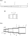
- FIGs. 1(A) and (B) are side views of a golf shaft according to the embodiment 1 of the present invention, in which FIG. 1(A) illustrates a whole of the golf shaft and FIG. 1(B) illustrates a part of FIG. 1(A) enlarged.
- FIG. 2 is a schematic longitudinal sectional view of the golf shaft.
- FIG. 3 is a schematic cross sectional view of the golf shaft taken along a line III-III of FIG. 2 . It should be noted that, although FIGs. 1(A)-3 do not correspond with each other in dimension of each part, they are basically the same structure.
- a golf shaft 1 of the present embodiment has a tip end 1a in an axial direction that is a portion to attach a head of a golf club thereto, and a base end 1b in the axial direction of the golf shaft 1 that is a portion to attach a grip of the golf club thereto.
- the golf shaft 1 is a metal shaft, and is formed to have an element tube 3, and a colored plating layer 5.
- the element tube 3 is a hollow tube, a sectional shape in a cross section of which is circular.
- the element tube 3 is made of metal, in particular steel.
- the material of the element tube 3 may be, however, the other material such as aluminum, titan, either alloy of them or the like.
- the element tube 3 of the present embodiment has a stepped outer shape, and is configured by a plurality of straight tube parts 3a and a plurality of tapered tube parts 3b each connecting adjacent straight tube parts 3a.
- the straight tube part 3a is a portion at which a wall thickness and diameters of inner and outer peripheries are constant.
- the straight tube part 3a located on the base end 1b side has the larger diameters of the inner and outer peripheries and the thinner wall thickness than the straight tube part 3a located on the tip end 1a side.
- Each tapered tube part 3b is to absorb differences in diameter and wall thickness between adjacent straight tube parts 3a.
- Each tapered tube part 3b gradually increases in the diameters of the inner and outer peripheries and becomes gradually thin in the wall thickness from the tip end 1a side toward the base end 1b side. Lengths of the tapered tube parts 3b in the axial direction are shorter than of the straight tube parts 3a.
- the element tube 3 is an example on which the colored plating layer 5 is formed. Accordingly, the element tube 3 is not limited to the stepped one, but may have a straight shape with a constant diameter of the outer periphery or an entirely tapered tubular shape. Further, the wall thickness of the element tube 3 may be constant or partially altered in the axial direction. Furthermore, the sectional shape in the cross section of the element tube 3 is not limited to the circular shape and may be an oval shape or the like appropriately selected.
- the colored plating layer 5 is a colored layer formed on a surface of the element tube 3.
- a color of the colored plating layer 5 is mat black according to the present embodiment, but may be the other color such as mat silver or mat grey.
- FIG. 4 is a schematic sectional view illustrating a layer structure of the colored plating layer 5.
- the colored plating layer 5 of the present embodiment is configured by a semigloss plating layer 7, a first strike plating layer 9, a satin-like plating layer 11, a second strike plating layer 13, a decorative plating layer 15, and a chromated layer 17 sequentially layered from the surface of the element tuber 3.
- the semigloss plating layer 7 is formed of a coating of semigloss plating layered on the surface of the element tube 3.
- the material of the semigloss plating layer 7 may be nickel, copper, gold, tin or the like according to the material of the element tube 3.
- the semigloss plating layer 7 of the present embodiment is a coating of semigloss nickel plating, the material of which is nickel.
- the semigloss plating layer 7 has a mat metallic (silver) appearance with, for example, a degree of gloss being about 0.3-0.5, a content percentage of sulfur constituent of which is about 0.005% less than the order of 0.01%, and a thickness of which is 4 ⁇ m-14 ⁇ m, for example, about 6.7 ⁇ m.
- the degree of gloss, the content percentage of sulfur constituent, the thickness and the like of the semigloss plating layer 7 are not limited thereto.
- the first strike plating layer 9 is layered on a surface of the semigloss plating layer 7 as a coating of strike plating on the element tube 3 side.
- the material of the first strike plating layer 9 may be nickel, silver, copper, gold, palladium or the like according to the materials of the semigloss plating layer 7 and the satin-like plating layer 11.
- the first strike plating layer 9 of the present embodiment is formed of a coating of nickel strike plating, the material of which is nickel.
- the first strike plating layer 9 has a metallic (silver) appearance.
- a content percentage of sulfur constituent of the first strike plating layer 9 is the order of 0.1%, and a thickness of the first strike plating layer 9 is very thin and about 0.1 ⁇ m-0.3 ⁇ m, for example, about 0.24 ⁇ m.
- the content percentage of sulfur constituent, the thickness and the like of the first strike plating layer 9 are not, however, limited thereto.
- the satin-like plating layer 11 is layered as a coating of satin-like plating on a surface of the first strike plating layer 9.
- the coating formed by the satin-like plating has fine irregularities on a surface thereof to have a velvet-like appearance.
- the satin-like plating will be explained later.
- the material of the satin-like plating layer 11 may be nickel, cobalt, copper or the like according to the materials of the first strike plating layer 9 and the second strike plating layer 13.
- the satin-like plating layer 11 of the present embodiment is formed of a coating of velour nickel plating that is nickel.
- the satin-like plating layer 11 has a thickness of about 4 ⁇ m-14 ⁇ m, for example, about 9.89 ⁇ m and is thicker than the first strike plating layer 9 and the semigloss plating layer 7. It should be noted that the thickness of the satin-like plating layer 11 is not limited thereto.
- the surface of the satin-like plating layer 11 has a mat or almost matrix metallic (silver) appearance. A hardness of the satin-like plating layer 11 is lower than of the first strike plating layer 9 and the second strike plating layer 13.
- the second strike plating layer 13 is a coating of strike plating layered on the surface of the satin-like plating layer 11, and is the same coating of the nickel strike plating as the first strike plating layer 9 according to the present embodiment.
- the same means that specifications of the material, the thickness and the like are the same. It should be noted that the second strike plating layer 13 may not be the same as the first strike plating layer 9 and may be altered in material, thickness and the like.
- the decorative plating layer 15 is formed of a coating of decorative plating layered outside the second strike plating layer 13, on a surface of the second strike plating layer 13 according to the present embodiment.
- the decorative plating layer 15 is colored according to the color of the colored plating layer 5.
- the colored according to the color of the colored plating layer 5 means a color tone except for the presence or absence of gloss and metallic feeling. In the case that the color plating layer 5 is mat black, therefore, the decorative plating layer 15 has a black color tone.
- the metallic feeling is a state that the metallic color of the lower layer is seen through the decorative plating layer 15.
- the decorative plating layer 15 may be formed of a coating of trivalent chromium plating, quadrivalent chromium plating or the like.
- the decorative plating layer 15 of the present embodiment is formed of a coating of black trivalent chromium plating.
- nickel plating, zinc plating and the like are nickel plating, zinc plating and the like other than the trivalent chromium plating for the coating of the black decorative plating layer.
- the decorative plating layer 15 may be silver (white), grey or the like in the case of the coating of the trivalent chromium plating.
- the grey is an intermediate color between black and white. If the decorative plating layer 15 is colored in white, the colored plating layer 5 has a mat silver color, and if the decorative plating layer 15 is colored in grey, the colored plating layer 5 has a mat grey color.
- a thickness of the decorative plating layer 15 is about 0.1 ⁇ m-0.5 ⁇ m, for example, about 0.31 ⁇ m.
- the chromated layer 17 is formed of a coating by means of chromate treatment layered on a surface of the decorative plating layer 15.
- the chromated layer 17 improves corrosion resistance and discoloration resistance of the colored plating layer 5.
- the chromated layer 17 may be colorless and transparent or colored, and is colorless and transparent according to the present embodiment.
- a thickness of the chromated layer 17 is about 1 to tens nm.
- FIGs. 5 are schematic sectional views illustrating a forming method of the colored plating layer of the golf shaft.
- the semigloss plating layer 7 is layered on the surface of the element tube 3 of the golf shaft 1 and the first strike plating layer 9 is layered on the surface of the semigloss plating layer 7 in a first line as illustrated in FIG. 5(A) , first.
- the semigloss nickel plating is conducted to the element tube 3 in the formation of the semigloss plating layer 7.
- the semigloss nickel plating should adopt a known one and is conducted by electro nickel plating or the like with a nickel plating bath into which a semigloss additive is added.
- the nickel plating bath composed mainly of, for example, nickel chloride, nickel sulfate, and boric acid is used.
- the semigloss additive should be a semigloss additive making the semigloss plating layer 7 include no sulfur (for example, making the content percentage become less than 0.05% in measurement using a fluorescent X-ray), and Acuna SL-MU manufactured by OKUNO Chemical Industries Co., Ltd. or the like may be used as the semigloss additive, for example.
- nickel sulfate is 240-320g/L
- nickel chloride is 30-50g/L
- boric acid is 30-50g/L
- Acuna SL-MU is 1-3ml/L.
- the first strike plating layer 9 is formed in the same first line.
- the nickel strike plating is conducted to the element tube 3 having the semigloss plating layer 7 in the formation of the first strike plating layer 9.
- the nickel strike plating should adopt a known one, and is conducted using a strike bath or the like composed mainly of, for example, nickel chloride, and hydrochloric acid.
- a strike bath or the like composed mainly of, for example, nickel chloride, and hydrochloric acid.
- hydrochloric acid is 110 ⁇ 15ml/L
- nickel chloride is 270 ⁇ 30g/L.
- boric acid functioning as a buffer agent and a mist suppressant may be added to the strike bath.
- the satin-like plating layer 11 is layered on the surface of the first strike plating layer 9 and the second strike plating layer 13 is layered on the surface of the satin-like plating layer 11 in the second line as illustrated in FIG. 5(B) .
- the velour nickel plating is conducted to the element tube 3 on which the first strike plating layer 9 is formed in the formation of the satin-like plating layer 11.
- the velour nickel plating should adopt a known one, and is conducted by the electro nickel plating or the like using a velour plating bath in which additives are added to a nickel plating bath composed mainly of, for example, nickel sulfate, nickel chloride, and boric acid.
- nickel sulfate is 270 ⁇ 25g/L
- nickel chloride is 50 ⁇ 10g/L
- boric acid is 35 ⁇ 5g/L
- a velour additive#50 is 30 ⁇ 8ml/L
- a velour additive#30 is 2.5 ⁇ 0.5ml/L.
- the satin-like plating includes plating such as satin plating and velour plating to provide a formed coating with a velvet-like appearance.
- the satin-like plating Dia satin manufactured by C.Uyemura & Co.,Ltd., Sachilite nickel manufactured by JCU CORPORATION and the like are known in addition to velour nickel.
- the second strike plating layer 13 is formed in the same second line.
- the nickel strike plating being the same as at the time of forming the first strike plating layer 9 is conducted to the element tube 3 on which the satin-like plating layer 11 is formed, in the formation of the second strike plating layer 13.
- the decorative plating layer 15 is layered on the surface of the second strike plating layer 13 in the third line as illustrated in FIG. 5(C) .
- the black trivalent chromium plating is conducted to the element tube 3 on which the second strike plating layer 13 is formed in the formation of the decorative plating layer 15.
- the black trivalent chromium plating adopt a known one, and is conducted using a black trivalent chromium plating bath composed mainly of a trivalent chromium compound and including an additive for the black color.
- a black trivalent chromium plating bath composed mainly of a trivalent chromium compound and including an additive for the black color.
- the black trivalent chromium plating bath there is Trichrome graphite manufactured by Atotech Japan. It should be noted that the black trivalent chromium plating is varied in color tone of black according to a manufacturer and may be bluish black, reddish black or the like.
- the decorative plating layer 15 is in white (silver), white trivalent chromium plating should be conducted instead of the black trivalent chromium plating.
- a white trivalent chromium plating bath such as Trichrome plus manufactured by Atotech Japan is used for example.
- a plating bath which is the plating bath of the black trivalent chromium plating adjusted in color tone should be used to conduct the trivalent chromium plating.
- the grey plating solution there is Top fine chrome LG manufacture by OKUNO Chemical Industries Co., Ltd.
- the chromated layer 17 is formed on the decorative plating layer 15 as illustrated in FIG. 5(D) .
- the chromated layer 17 may be formed by known chromate treatment.
- electrolytic chromate treatment using chromate treatment solution composed mainly of, for example, a trivalent chromium compound is conducted to the element tube 3 on which the decorative plating layer 15 is formed.
- the chromated layer 17 is formed to finish the colored plating layer 5 of the golf shaft 1.
- the semigloss plating layer 7 is mat metallic color
- the first and the second strike plating layers 9 and 13 are metallic color
- the satin-like plating layer 11 is mat metallic color
- the decorative plating layer 15 is black
- the chromated layer 17 is colorless and transparent
- the finished colored plating layer 5 is mat black as a whole.
- the decorative plating layer 15 is in white (silver), the whole is mat silver, and if the decorative plating layer 15 is in grey, the whole is mat grey.
- the golf shaft 1 of the present embodiment obtains the colored plating layer 5 with high durability while being mat black.
- FIGs. 6(A) and 6(B) are photographs illustrating states of colored layers of the golf shafts 1 after a scratch test, in which FIG. 6(A) is an embodied product and FIG. 6(B) is a comparative example product.
- black and white are inverted to be indicated in view of visibility.
- the embodied product is the golf shaft 1 of the present embodiment and the comparative example product is that a paint film layer is formed as a colored layer on a decorative plating layer after sequentially forming a semigloss plating layer, a gloss plating layer, a seal plating layer and the decorative plating layer from a surface of an element tube similar to a general golf shaft.
- a paint film layer is formed as a colored layer on a decorative plating layer after sequentially forming a semigloss plating layer, a gloss plating layer, a seal plating layer and the decorative plating layer from a surface of an element tube similar to a general golf shaft.
- Each of the semigloss plating layer, the gloss plating layer, and the seal plating layer is a coating of nickel plating having a sealing property (see embodiment 2 for details)
- the decorative plating layer is a coating of hexavalent chromium plating
- the paint film layer is a coating of black painting.
- the scratch test was conducted by rubbing the embodied product and the comparative example product intersecting with each other. As a result, visible scratches S were occurred on the comparative example product whereas no visible scratch was occurred on the embodied product.
- the golf shaft 1 of the present embodiment ensures peeling resistance of the colored layer to endure a bending process and the like. It should be noted that the peeling resistance means difficulty in peeling off. In the golf shaft 1 of the embodied product, no peeling was occurred even when bending is conducted at a bending angle of 30 degrees with a curvature radius of 60mm. On the other hand, in the golf shaft of the comparative example product, peeling of the paint film layer was occurred by the similar bending. In addition, the bending was conducted by a press. In a golf shaft for a putter, there are one bending or two bendings and the bendings require bending angles of about 5-25 degrees, and the golf shaft 1 of the present embodiment obtains the colored layer enduring the bending requirement.
- the peeling resistance of the embodied product is obtained by that the first strike plating layer 9 improves adhesion between the semigloss plating layer 7 and the satin-like plating layer 11 and the second strike plating layer 13 improves adhesion between the satin-like plating layer 11 and the decorative plating layer 15.
- first and the second strike plating layers 9 and 13 have the same structure, so that adhering situations of the semigloss plating layer 7 and the decorative plating layer 15 with respect to the satin-like plating layer 11 are uniformed on both sides in a layer direction, thereby to prevent interfacial failure between the satin-like plating layer 11 and the semigloss plating layer 7 and the decorative plating layer 15, respectively.
- the layer direction means a layering direction of each layer of the colored plating layer 5.
- first and the second strike plating layers 9 and 13 have relatively low rigidity, and the first and the second strike plating layers 9 and 13 function as binders each for an inter-layer to improve a followability of the colored plating layer 5 to a bending.
- the golf shaft 1 of the present embodiment is provided with the element tube 3 made of metal, and the colored plating layer 5 being the colored layer formed on the surface of the element tube 3.
- the colored plating layer 5 is provided with the semigloss plating layer 7 layered on the surface of the element tube 3, the first strike plating layer 9 layered on the surface of the semigloss plating layer 7, the satin-like plating layer 11 layered on the surface of the first strike plating layer 9, the second strike plating layer 13 layered on the surface of the stain-like plating layer 11, and the decorative plating layer 15 layered on the surface of the second strike plating layer 13 and colored according to the color of the colored plating layer 5.
- the present embodiment therefore, improves in adhesion due to the first strike plating layer 9 and the second strike plating layer 13 and functions the first and the second strike plating layers 9 and 13 as the binders each for the inter-layer to improve the followability of the colored plating layer 5. This ensures the peeling resistance of the colored layer to endure a bending process and the like for the golf shaft 1.
- the colored plating layer 5 improves in adhesion to the element tube due to the semigloss plating layer 7, to ensure the peeling resistance of the whole colored layer relative to the element tube 3 and certainly obtain the mat color. Furthermore, the present embodiment gives the mat color, in particular mat black, due to the layer structure of the colored plating layer 5, so that high scratch resistance is obtained while colored in mat black. In addition, the case in which the colored plating layer 5 is colored in mat silver or mat grey also provides the same effect.
- the second strike plating layer 13 is the same as the first strike plating layer 9. Accordingly, the adhering situations of the semigloss plating layer 7 and the decorative plating layer 15 with respect to the satin-like plating layer 11 are uniformed, thereby to prevent interfacial failure between the satin-like plating layer 11 and the semigloss plating layer 7 and the decorative plating layer 15.
- the element tube 3 is made of steel, and the semigloss plating layer 7, the first strike plating layer 9, the satin-like plating layer 11, and the second strike plating layer 13 are formed of the nickel platings, and the decorative plating layer 15 is formed of the trivalent chromium plating.
- the peeling resistance of the whole colored layer relative to the element tube 3 is, therefore, further certainly obtained.
- the colored plating layer 5 is provided with the chromated layer 17 layered on the surface of the decorative plating layer 15, so that the golf shaft 1 improves in corrosion resistance.
- the method of manufacturing the golf shaft 1 layers the semigloss plating layer 7 on the surface of the element tube 3 and layers the first strike plating layer 9 on the surface of the semigloss plating layer 7 in the first line, layers the satin-like plating layer 11 on the surface of the first strike plating layer 9 and layers the second strike plating layer 13 on the surface of the satin-like plating layer 11 in the second line, and layers the decorative plating layer 15 on the surface of the second strike plating layer 13 in the third line.
- the golf shaft 1 the colored layer of which has the peeling resistance to endure a bending process and the like.
- FIG. 7 is a schematic sectional view illustrating a layer structure of a colored plating layer of a golf shaft according to the embodiment 2 of the present invention.
- components being the same as those of the embodiment 1 are represented with the same reference numerals to eliminate repetition in description.
- a golf shaft 1 of the present embodiment is provided with a seal plating layer 19 instead of the chromated layer 17.
- the other configuration is the same as of the embodiment 1.
- the seal plating layer 19 is provided between a second strike plating layer 13 and a decorative plating layer 15. Namely, the seal plating layer 19 is layered on a surface of the second strike plating layer 13, and the decorative plating layer 15 is layered on a surface of the seal plating layer 19.
- the present embodiment therefore, is configured that the decorative plating layer 15 is layered outside the second strike plating layer 13 through the seal plating layer 19.
- the seal plating layer 19 employs material in which a sealing property is added to nickel or the like that is relatively hard metal, or material which is indium, gold, silver or the like that is relatively soft metal.
- the material of the seal plating layer 19 of the present embodiment is a coating of seal nickel plating as nickel to which the sealing property is added.
- the seal nickel plating is conducted to the element tube 3 to which the second strike plating layer 11 is formed thus far.
- the seal nickel plating should adopt a known one, and is conducted by the electro nickel plating or the like using a seal plating bath in which additives are added to a nickel plating bath composed mainly of, for example, nickel sulfate, nickel chloride, and boric acid.
- nickel sulfate is 180 ⁇ 40g/L
- nickel chloride is 25 ⁇ 8g/L
- boric acid is 25 ⁇ 8g/L.
- As the additive used in the seal plating bath there are Improved acuna B-1, Improved acuna B-2, Seal nickel HCR-K-4, Seal nickel SMPC-4 and the like manufactured by OKUNO Chemical Industries Co., Ltd.
- the embodiment 2 provides the same effects as the embodiment 1.
Landscapes
- Chemical & Material Sciences (AREA)
- Metallurgy (AREA)
- Materials Engineering (AREA)
- Organic Chemistry (AREA)
- Engineering & Computer Science (AREA)
- Chemical Kinetics & Catalysis (AREA)
- Electrochemistry (AREA)
- Inorganic Chemistry (AREA)
- Mechanical Engineering (AREA)
- Physical Education & Sports Medicine (AREA)
- General Health & Medical Sciences (AREA)
- Health & Medical Sciences (AREA)
- Electroplating Methods And Accessories (AREA)
- Golf Clubs (AREA)
- Laminated Bodies (AREA)
- Other Surface Treatments For Metallic Materials (AREA)
- Lining Or Joining Of Plastics Or The Like (AREA)
Abstract
Description
- The present invention relates to a golf shaft in which an element tube made of metal is covered with a colored plating layer and a method of manufacturing the same.
- A golf shaft made of a metal element tube (hereinafter referred to as "metal shaft" in some cases) generally has a metallic color in appearance, it is a simple design and another color may be desired instead of the metallic color. As a coloring technique for such a metal shaft, there is disclosed in
Patent document 1, for example. - The technique of
Patent document 1 forms a nickel coating layer on a surface of a metal element tube, a chromium plating coating layer on a surface of the nickel coating layer, and a color anion electrodeposition paint film layer as a colored layer on a surface of the chromium plating coating layer. - The technique enhances designability of the metal shaft with color. The colored layer according to the paint film, however, has low adhesion and is peeled off if the metal shaft is subjected to a bending process for a putter or the like.
- PATENT DOCUMENT 1:
JP 3157018 U - A problem to be solved is that a colored layer tends to be peeled off in a bending process or the like.
- The present invention provides a golf shaft comprising an element tube made of metal, and a colored plating layer being a colored layer formed on a surface of the element tube, wherein the colored plating layer comprises a semigloss plating layer layered on the surface of the element tube, a first strike plating layer layered on a surface of the semigloss plating layer, a satin-like plating layer layered on a surface of the first strike plating layer, a second strike plating layer layered on a surface of the stain-like plating layer, and a decorative plating layer layered outside the second strike plating layer and colored according to a color of the colored plating layer.
- Further, the present invention provides a method of manufacturing the golf shaft, comprising in a first line, layering the semigloss plating layer on the surface of the element tube and layering the first strike plating layer on the surface of the semigloss plating layer, in a second line, layering the satin-like plating layer on the surface of the first strike plating layer and layering the second strike plating layer on the surface of the satin-like plating layer, and in a third line, layering the decorative plating layer outside the second strike plating layer.
- The present invention ensures peeling resistance of the colored layer to endure even a bending process and the like.
-
- [
FIG. 1] FIGs. 1(A) and (B) are side views of a golf shaft according to anembodiment 1 of the present invention, in whichFIG. 1(A) illustrates a whole of the golf shaft andFIG. 1(B) illustrates a part ofFIG. 1(A) enlarged. - [
FIG. 2] FIG. 2 is a schematic longitudinal sectional view of the golf shaft ofFIG. 1 . - [
FIG. 3] FIG. 3 is a schematic cross sectional view of the golf shaft taken along a line III-III ofFIG. 2 . - [
FIG. 4] FIG. 4 is a schematic sectional view of a layer structure of a colored plating layer of the golf shaft ofFIG. 3 . - [
FIG. 5] FIGs. 5 are schematic sectional views illustrating a forming method of the colored plating layer of the golf shaft. - [
FIG. 6] FIGs. 6(A) and 6(B) are photographs illustrating states of colored layers of golf shafts after a scratch test, in whichFIG. 6(A) is an embodied product and -
FIG. 6(B) is a comparative example product. - [
FIG. 7] FIG. 7 is a schematic sectional view illustrating a layer structure of a colored plating layer of a golf shaft according to an embodiment 2 of the present invention. - The present invention accomplishes the object of ensuring peeling resistance of a colored layer to endure even a bending process and the like by a layer structure of a colored plating layer being the colored layer formed on a surface of an element tube made of metal.
- Namely, a golf shaft (1) comprises an element tube (3) made of metal, and a colored plating layer (5) being a colored layer formed on a surface of the element tube (3). The colored plating layer (5) comprises a semigloss plating layer (7), a first strike plating layer (9), a satin-like plating layer (11), a second strike plating layer (13) and a decorative plating layer (15). The semigloss plating layer (7) is layered on the surface of the element tube (3). The first strike plating layer (9) is layered on a surface of the semigloss plating layer (7). The satin-like plating layer (11) is layered on a surface of the first strike plating layer (9). The second strike plating layer (13) is layered on a surface of the stain-like plating layer (11). The decorative plating layer (15) is layered outside the second strike plating layer (13) and is colored according to a color of the colored plating layer (5).
- It may be configured that the element tube (3) is made of steel, the semigloss plating layer (7), the first strike plating layer (9), the satin-like plating layer (11), and the second strike plating layer (13) are formed of coatings of nickel plating, and the decorative plating layer (15) is formed of a coating of trivalent chromium plating.
- It may be configured that the decorative plating layer (15) is layered on a surface of the second strike plating layer (13) and the colored plating layer (5) further comprises a chromated layer (17) layered on a surface of the decorative plating layer (15).
- It may be configured that the colored plating layer (5) further comprises a seal plating layer (19) layered on a surface of the second strike plating layer (13) and the decorative plating layer (15) is layered on a surface of the seal plating layer (19).
- A color of the colored plating layer (5) may be mat black, mat silver or mat grey.
- A method of manufacturing the golf shaft may perform plating at a first line, a second line and a third line. In this case, in the first line, the semigloss plating layer (7) is layered on the surface of the element tube (3) and the first strike plating layer (9) is layered on the surface of the semigloss plating layer (7). In the second line, the satin-like plating layer (11) is layered on the surface of the first strike plating layer (9) and the second strike plating layer (13) is layered on the surface of the satin-like plating layer (11). In the third line, the decorative plating layer (15) is layered outside the second strike plating layer (13).
-
FIGs. 1(A) and (B) are side views of a golf shaft according to theembodiment 1 of the present invention, in whichFIG. 1(A) illustrates a whole of the golf shaft andFIG. 1(B) illustrates a part ofFIG. 1(A) enlarged.FIG. 2 is a schematic longitudinal sectional view of the golf shaft.FIG. 3 is a schematic cross sectional view of the golf shaft taken along a line III-III ofFIG. 2 . It should be noted that, althoughFIGs. 1(A)-3 do not correspond with each other in dimension of each part, they are basically the same structure. - A
golf shaft 1 of the present embodiment has atip end 1a in an axial direction that is a portion to attach a head of a golf club thereto, and abase end 1b in the axial direction of thegolf shaft 1 that is a portion to attach a grip of the golf club thereto. Thegolf shaft 1 is a metal shaft, and is formed to have anelement tube 3, and acolored plating layer 5. - The
element tube 3 is a hollow tube, a sectional shape in a cross section of which is circular. Theelement tube 3 is made of metal, in particular steel. The material of theelement tube 3 may be, however, the other material such as aluminum, titan, either alloy of them or the like. - The
element tube 3 of the present embodiment has a stepped outer shape, and is configured by a plurality ofstraight tube parts 3a and a plurality oftapered tube parts 3b each connecting adjacentstraight tube parts 3a. - The
straight tube part 3a is a portion at which a wall thickness and diameters of inner and outer peripheries are constant. Thestraight tube part 3a located on thebase end 1b side has the larger diameters of the inner and outer peripheries and the thinner wall thickness than thestraight tube part 3a located on thetip end 1a side. - Each
tapered tube part 3b is to absorb differences in diameter and wall thickness between adjacentstraight tube parts 3a. Eachtapered tube part 3b gradually increases in the diameters of the inner and outer peripheries and becomes gradually thin in the wall thickness from thetip end 1a side toward thebase end 1b side. Lengths of thetapered tube parts 3b in the axial direction are shorter than of thestraight tube parts 3a. - It should be noted that the
element tube 3 is an example on which thecolored plating layer 5 is formed. Accordingly, theelement tube 3 is not limited to the stepped one, but may have a straight shape with a constant diameter of the outer periphery or an entirely tapered tubular shape. Further, the wall thickness of theelement tube 3 may be constant or partially altered in the axial direction. Furthermore, the sectional shape in the cross section of theelement tube 3 is not limited to the circular shape and may be an oval shape or the like appropriately selected. - The
colored plating layer 5 is a colored layer formed on a surface of theelement tube 3. A color of thecolored plating layer 5 is mat black according to the present embodiment, but may be the other color such as mat silver or mat grey. -
FIG. 4 is a schematic sectional view illustrating a layer structure of thecolored plating layer 5. - The
colored plating layer 5 of the present embodiment is configured by a semigloss plating layer 7, a firststrike plating layer 9, a satin-like plating layer 11, a secondstrike plating layer 13, adecorative plating layer 15, and achromated layer 17 sequentially layered from the surface of theelement tuber 3. - The semigloss plating layer 7 is formed of a coating of semigloss plating layered on the surface of the
element tube 3. The material of the semigloss plating layer 7 may be nickel, copper, gold, tin or the like according to the material of theelement tube 3. The semigloss plating layer 7 of the present embodiment is a coating of semigloss nickel plating, the material of which is nickel. - The semigloss plating layer 7 has a mat metallic (silver) appearance with, for example, a degree of gloss being about 0.3-0.5, a content percentage of sulfur constituent of which is about 0.005% less than the order of 0.01%, and a thickness of which is 4µm-14µm, for example, about 6.7µm. The degree of gloss, the content percentage of sulfur constituent, the thickness and the like of the semigloss plating layer 7 are not limited thereto.
- The first
strike plating layer 9 is layered on a surface of the semigloss plating layer 7 as a coating of strike plating on theelement tube 3 side. The material of the firststrike plating layer 9 may be nickel, silver, copper, gold, palladium or the like according to the materials of the semigloss plating layer 7 and the satin-like plating layer 11. The firststrike plating layer 9 of the present embodiment is formed of a coating of nickel strike plating, the material of which is nickel. - The first
strike plating layer 9 has a metallic (silver) appearance. A content percentage of sulfur constituent of the firststrike plating layer 9 is the order of 0.1%, and a thickness of the firststrike plating layer 9 is very thin and about 0.1µm-0.3µm, for example, about 0.24µm. The content percentage of sulfur constituent, the thickness and the like of the firststrike plating layer 9 are not, however, limited thereto. - The satin-
like plating layer 11 is layered as a coating of satin-like plating on a surface of the firststrike plating layer 9. The coating formed by the satin-like plating has fine irregularities on a surface thereof to have a velvet-like appearance. In addition, the satin-like plating will be explained later. - The material of the satin-
like plating layer 11 may be nickel, cobalt, copper or the like according to the materials of the firststrike plating layer 9 and the secondstrike plating layer 13. The satin-like plating layer 11 of the present embodiment is formed of a coating of velour nickel plating that is nickel. - The satin-
like plating layer 11 has a thickness of about 4µm-14µm, for example, about 9.89µm and is thicker than the firststrike plating layer 9 and the semigloss plating layer 7. It should be noted that the thickness of the satin-like plating layer 11 is not limited thereto. The surface of the satin-like plating layer 11 has a mat or almost matrix metallic (silver) appearance. A hardness of the satin-like plating layer 11 is lower than of the firststrike plating layer 9 and the secondstrike plating layer 13. - The second
strike plating layer 13 is a coating of strike plating layered on the surface of the satin-like plating layer 11, and is the same coating of the nickel strike plating as the firststrike plating layer 9 according to the present embodiment. In addition, the same means that specifications of the material, the thickness and the like are the same. It should be noted that the secondstrike plating layer 13 may not be the same as the firststrike plating layer 9 and may be altered in material, thickness and the like. - The
decorative plating layer 15 is formed of a coating of decorative plating layered outside the secondstrike plating layer 13, on a surface of the secondstrike plating layer 13 according to the present embodiment. Thedecorative plating layer 15 is colored according to the color of thecolored plating layer 5. The colored according to the color of thecolored plating layer 5 means a color tone except for the presence or absence of gloss and metallic feeling. In the case that thecolor plating layer 5 is mat black, therefore, thedecorative plating layer 15 has a black color tone. In addition, the metallic feeling is a state that the metallic color of the lower layer is seen through thedecorative plating layer 15. - The
decorative plating layer 15 may be formed of a coating of trivalent chromium plating, quadrivalent chromium plating or the like. Thedecorative plating layer 15 of the present embodiment is formed of a coating of black trivalent chromium plating. In addition, there are nickel plating, zinc plating and the like other than the trivalent chromium plating for the coating of the black decorative plating layer. - Further, the
decorative plating layer 15 may be silver (white), grey or the like in the case of the coating of the trivalent chromium plating. The grey is an intermediate color between black and white. If thedecorative plating layer 15 is colored in white, thecolored plating layer 5 has a mat silver color, and if thedecorative plating layer 15 is colored in grey, thecolored plating layer 5 has a mat grey color. A thickness of thedecorative plating layer 15 is about 0.1µm-0.5µm, for example, about 0.31µm. - The
chromated layer 17 is formed of a coating by means of chromate treatment layered on a surface of thedecorative plating layer 15. Thechromated layer 17 improves corrosion resistance and discoloration resistance of thecolored plating layer 5. Thechromated layer 17 may be colorless and transparent or colored, and is colorless and transparent according to the present embodiment. A thickness of thechromated layer 17 is about 1 to tens nm. -
FIGs. 5 are schematic sectional views illustrating a forming method of the colored plating layer of the golf shaft. - When forming the
colored plating layer 5 on thegolf shaft 1, the semigloss plating layer 7 is layered on the surface of theelement tube 3 of thegolf shaft 1 and the firststrike plating layer 9 is layered on the surface of the semigloss plating layer 7 in a first line as illustrated inFIG. 5(A) , first. - Since the semigloss plating layer 7 is the coating of the semigloss nickel plating, the semigloss nickel plating is conducted to the
element tube 3 in the formation of the semigloss plating layer 7. The semigloss nickel plating should adopt a known one and is conducted by electro nickel plating or the like with a nickel plating bath into which a semigloss additive is added. The nickel plating bath composed mainly of, for example, nickel chloride, nickel sulfate, and boric acid is used. - The semigloss additive should be a semigloss additive making the semigloss plating layer 7 include no sulfur (for example, making the content percentage become less than 0.05% in measurement using a fluorescent X-ray), and Acuna SL-MU manufactured by OKUNO Chemical Industries Co., Ltd. or the like may be used as the semigloss additive, for example.
- In an example of the nickel plating bath, nickel sulfate is 240-320g/L, nickel chloride is 30-50g/L, boric acid is 30-50g/L, and Acuna SL-MU is 1-3ml/L.
- On the semigloss plating layer 7, the first
strike plating layer 9 is formed in the same first line. - Since the first
strike plating layer 9 is formed of the coating of the nickel strike plating, the nickel strike plating is conducted to theelement tube 3 having the semigloss plating layer 7 in the formation of the firststrike plating layer 9. - The nickel strike plating should adopt a known one, and is conducted using a strike bath or the like composed mainly of, for example, nickel chloride, and hydrochloric acid. In an example of the strike bath, hydrochloric acid is 110±15ml/L, and nickel chloride is 270±30g/L. In addition, boric acid functioning as a buffer agent and a mist suppressant may be added to the strike bath.
- With the formation of the first
strike plating layer 9, an oxide film formed at the time of drying the semigloss plating layer 7 is removed and is prevented from being formed again, and adhesion of the subsequent satin-like plating layer 11 containing oil is improved. - Next, the satin-
like plating layer 11 is layered on the surface of the firststrike plating layer 9 and the secondstrike plating layer 13 is layered on the surface of the satin-like plating layer 11 in the second line as illustrated inFIG. 5(B) . - Since the satin-
like plating layer 11 is formed of the coating of the velour nickel plating, the velour nickel plating is conducted to theelement tube 3 on which the firststrike plating layer 9 is formed in the formation of the satin-like plating layer 11. The velour nickel plating should adopt a known one, and is conducted by the electro nickel plating or the like using a velour plating bath in which additives are added to a nickel plating bath composed mainly of, for example, nickel sulfate, nickel chloride, and boric acid. - In an example of the velour plating bath, nickel sulfate is 270±25g/L, nickel chloride is 50±10g/L, boric acid is 35±5g/L, and a velour additive#50 is 30±8ml/L, and a velour additive#30 is 2.5±0.5ml/L.
- In addition, the satin-like plating includes plating such as satin plating and velour plating to provide a formed coating with a velvet-like appearance. As the satin-like plating, Dia satin manufactured by C.Uyemura & Co.,Ltd., Sachilite nickel manufactured by JCU CORPORATION and the like are known in addition to velour nickel.
- On the satin-
like plating layer 11, the secondstrike plating layer 13 is formed in the same second line. - Since the second
strike plating layer 13 is the same as the first strike plating 9, the nickel strike plating being the same as at the time of forming the firststrike plating layer 9 is conducted to theelement tube 3 on which the satin-like plating layer 11 is formed, in the formation of the secondstrike plating layer 13. - With the formation of the second
strike plating layer 13, an oxide film is prevented from being formed on the satin-like plating layer 11, and adhesion between the satin-like plating layer 9 containing oil and the subsequentdecorative plating layer 15 is improved. - Next, the
decorative plating layer 15 is layered on the surface of the secondstrike plating layer 13 in the third line as illustrated inFIG. 5(C) . - Since the
decorative plating layer 15 is formed of the coating of the black trivalent chromium plating, the black trivalent chromium plating is conducted to theelement tube 3 on which the secondstrike plating layer 13 is formed in the formation of thedecorative plating layer 15. - The black trivalent chromium plating adopt a known one, and is conducted using a black trivalent chromium plating bath composed mainly of a trivalent chromium compound and including an additive for the black color. In an example of the black trivalent chromium plating bath, there is Trichrome graphite manufactured by Atotech Japan. It should be noted that the black trivalent chromium plating is varied in color tone of black according to a manufacturer and may be bluish black, reddish black or the like.
- If the
decorative plating layer 15 is in white (silver), white trivalent chromium plating should be conducted instead of the black trivalent chromium plating. In the white trivalent chromium plating, a white trivalent chromium plating bath such as Trichrome plus manufactured by Atotech Japan is used for example. If thedecorative plating layer 15 is in grey, a plating bath which is the plating bath of the black trivalent chromium plating adjusted in color tone should be used to conduct the trivalent chromium plating. As an example of the grey plating solution, there is Top fine chrome LG manufacture by OKUNO Chemical Industries Co., Ltd. - Finally, the
chromated layer 17 is formed on thedecorative plating layer 15 as illustrated inFIG. 5(D) . - The
chromated layer 17 may be formed by known chromate treatment. As the chromate treatment, electrolytic chromate treatment using chromate treatment solution composed mainly of, for example, a trivalent chromium compound is conducted to theelement tube 3 on which thedecorative plating layer 15 is formed. - In this way, the
chromated layer 17 is formed to finish thecolored plating layer 5 of thegolf shaft 1. The semigloss plating layer 7 is mat metallic color, the first and the secondstrike plating layers like plating layer 11 is mat metallic color, thedecorative plating layer 15 is black, thechromated layer 17 is colorless and transparent, and the finishedcolored plating layer 5 is mat black as a whole. - If the
decorative plating layer 15 is in white (silver), the whole is mat silver, and if thedecorative plating layer 15 is in grey, the whole is mat grey. - Since the
decorative plating layer 15 on the surface layer of thecolored plating layer 5 is formed of the coating of the trivalent chromium plating, thegolf shaft 1 of the present embodiment obtains thecolored plating layer 5 with high durability while being mat black. -
FIGs. 6(A) and 6(B) are photographs illustrating states of colored layers of thegolf shafts 1 after a scratch test, in whichFIG. 6(A) is an embodied product andFIG. 6(B) is a comparative example product. In addition, inFIGs. 6 , black and white are inverted to be indicated in view of visibility. - The embodied product is the
golf shaft 1 of the present embodiment and the comparative example product is that a paint film layer is formed as a colored layer on a decorative plating layer after sequentially forming a semigloss plating layer, a gloss plating layer, a seal plating layer and the decorative plating layer from a surface of an element tube similar to a general golf shaft. Each of the semigloss plating layer, the gloss plating layer, and the seal plating layer is a coating of nickel plating having a sealing property (see embodiment 2 for details), the decorative plating layer is a coating of hexavalent chromium plating, and the paint film layer is a coating of black painting. - The scratch test was conducted by rubbing the embodied product and the comparative example product intersecting with each other. As a result, visible scratches S were occurred on the comparative example product whereas no visible scratch was occurred on the embodied product.
- The
golf shaft 1 of the present embodiment ensures peeling resistance of the colored layer to endure a bending process and the like. It should be noted that the peeling resistance means difficulty in peeling off. In thegolf shaft 1 of the embodied product, no peeling was occurred even when bending is conducted at a bending angle of 30 degrees with a curvature radius of 60mm. On the other hand, in the golf shaft of the comparative example product, peeling of the paint film layer was occurred by the similar bending. In addition, the bending was conducted by a press. In a golf shaft for a putter, there are one bending or two bendings and the bendings require bending angles of about 5-25 degrees, and thegolf shaft 1 of the present embodiment obtains the colored layer enduring the bending requirement. - The peeling resistance of the embodied product is obtained by that the first
strike plating layer 9 improves adhesion between the semigloss plating layer 7 and the satin-like plating layer 11 and the secondstrike plating layer 13 improves adhesion between the satin-like plating layer 11 and thedecorative plating layer 15. - Further, the first and the second
strike plating layers decorative plating layer 15 with respect to the satin-like plating layer 11 are uniformed on both sides in a layer direction, thereby to prevent interfacial failure between the satin-like plating layer 11 and the semigloss plating layer 7 and thedecorative plating layer 15, respectively. In addition, the layer direction means a layering direction of each layer of thecolored plating layer 5. - Further, the first and the second
strike plating layers strike plating layers colored plating layer 5 to a bending. Thecolored plating layer 5, therefore, has a structure strong against bending of thegolf shaft 1. - As mentioned above, the
golf shaft 1 of the present embodiment is provided with theelement tube 3 made of metal, and thecolored plating layer 5 being the colored layer formed on the surface of theelement tube 3. Thecolored plating layer 5 is provided with the semigloss plating layer 7 layered on the surface of theelement tube 3, the firststrike plating layer 9 layered on the surface of the semigloss plating layer 7, the satin-like plating layer 11 layered on the surface of the firststrike plating layer 9, the secondstrike plating layer 13 layered on the surface of the stain-like plating layer 11, and thedecorative plating layer 15 layered on the surface of the secondstrike plating layer 13 and colored according to the color of thecolored plating layer 5. - The present embodiment, therefore, improves in adhesion due to the first
strike plating layer 9 and the secondstrike plating layer 13 and functions the first and the secondstrike plating layers colored plating layer 5. This ensures the peeling resistance of the colored layer to endure a bending process and the like for thegolf shaft 1. - Further, the
colored plating layer 5 improves in adhesion to the element tube due to the semigloss plating layer 7, to ensure the peeling resistance of the whole colored layer relative to theelement tube 3 and certainly obtain the mat color. Furthermore, the present embodiment gives the mat color, in particular mat black, due to the layer structure of thecolored plating layer 5, so that high scratch resistance is obtained while colored in mat black. In addition, the case in which thecolored plating layer 5 is colored in mat silver or mat grey also provides the same effect. - Further, the second
strike plating layer 13 is the same as the firststrike plating layer 9. Accordingly, the adhering situations of the semigloss plating layer 7 and thedecorative plating layer 15 with respect to the satin-like plating layer 11 are uniformed, thereby to prevent interfacial failure between the satin-like plating layer 11 and the semigloss plating layer 7 and thedecorative plating layer 15. - The
element tube 3 is made of steel, and the semigloss plating layer 7, the firststrike plating layer 9, the satin-like plating layer 11, and the secondstrike plating layer 13 are formed of the nickel platings, and thedecorative plating layer 15 is formed of the trivalent chromium plating. - The peeling resistance of the whole colored layer relative to the
element tube 3 is, therefore, further certainly obtained. - The
colored plating layer 5 is provided with thechromated layer 17 layered on the surface of thedecorative plating layer 15, so that thegolf shaft 1 improves in corrosion resistance. - The method of manufacturing the
golf shaft 1 layers the semigloss plating layer 7 on the surface of theelement tube 3 and layers the firststrike plating layer 9 on the surface of the semigloss plating layer 7 in the first line, layers the satin-like plating layer 11 on the surface of the firststrike plating layer 9 and layers the secondstrike plating layer 13 on the surface of the satin-like plating layer 11 in the second line, and layers thedecorative plating layer 15 on the surface of the secondstrike plating layer 13 in the third line. - It, therefore, surely manufactures the
golf shaft 1, the colored layer of which has the peeling resistance to endure a bending process and the like. -
FIG. 7 is a schematic sectional view illustrating a layer structure of a colored plating layer of a golf shaft according to the embodiment 2 of the present invention. In addition, in the embodiment 2, components being the same as those of theembodiment 1 are represented with the same reference numerals to eliminate repetition in description. - A
golf shaft 1 of the present embodiment is provided with aseal plating layer 19 instead of thechromated layer 17. The other configuration is the same as of theembodiment 1. - The
seal plating layer 19 is provided between a secondstrike plating layer 13 and adecorative plating layer 15. Namely, theseal plating layer 19 is layered on a surface of the secondstrike plating layer 13, and thedecorative plating layer 15 is layered on a surface of theseal plating layer 19. The present embodiment, therefore, is configured that thedecorative plating layer 15 is layered outside the secondstrike plating layer 13 through theseal plating layer 19. - The
seal plating layer 19 employs material in which a sealing property is added to nickel or the like that is relatively hard metal, or material which is indium, gold, silver or the like that is relatively soft metal. The material of theseal plating layer 19 of the present embodiment is a coating of seal nickel plating as nickel to which the sealing property is added. - In the formation of the
seal plating layer 19, the seal nickel plating is conducted to theelement tube 3 to which the secondstrike plating layer 11 is formed thus far. The seal nickel plating should adopt a known one, and is conducted by the electro nickel plating or the like using a seal plating bath in which additives are added to a nickel plating bath composed mainly of, for example, nickel sulfate, nickel chloride, and boric acid. - In an example of the seal plating bath, nickel sulfate is 180±40g/L, nickel chloride is 25±8g/L, and boric acid is 25±8g/L. As the additive used in the seal plating bath, there are Improved acuna B-1, Improved acuna B-2, Seal nickel HCR-K-4, Seal nickel SMPC-4 and the like manufactured by OKUNO Chemical Industries Co., Ltd.
- The embodiment 2 provides the same effects as the
embodiment 1. -
- 1 Golf shaft
- 3 Element tube
- 5 Colored plating layer
- 7 Semigloss plating layer
- 9 First strike plating layer
- 11 Satin-like plating layer
- 13 Second strike plating layer
- 15 Decorative plating layer
- 17 Chromated layer
- 19 Seal plating layer
Claims (8)
- A golf shaft comprising:an element tube made of metal; anda colored plating layer being a colored layer formed on a surface of the element tube, whereinthe colored plating layer comprises:a semigloss plating layer layered on the surface of the element tube;a first strike plating layer layered on a surface of the semigloss plating layer;a satin-like plating layer layered on a surface of the first strike plating layer;a second strike plating layer layered on a surface of the stain-like plating layer; anda decorative plating layer layered outside the second strike plating layer and colored according to a color of the colored plating layer.
- The golf shaft according to claim 1, whereinthe element tube is made of steel,the semigloss plating layer, the first strike plating layer, the satin-like plating layer, and the second strike plating layer are formed of coatings of nickel plating, andthe decorative plating layer is formed of a coating of trivalent chromium plating.
- The golf shaft according to claim 1 or 2, whereinthe decorative plating layer is layered on a surface of the second strike plating layer, andthe colored plating layer further comprises a chromated layer layered on a surface of the decorative plating layer.
- The golf shaft according to claim 1 or 2, whereinthe colored plating layer further comprises a seal plating layer layered on a surface of the second strike plating layer, andthe decorative plating layer is layered on a surface of the seal plating layer.
- The golf shaft according to any one of claims 1 to 4, wherein
a color of the colored plating layer is mat black. - The golf shaft according to any one of claims 1 to 4, wherein
a color of the colored plating layer is mat silver. - The golf shaft according to any one of claims 1 to 4, wherein
a color of the colored plating layer is mat grey. - A method of manufacturing the golf shaft according to any one of claims 1 to 7, comprising:in a first line, layering the semigloss plating layer on the surface of the element tube and layering the first strike plating layer on the surface of the semigloss plating layer;in a second line, layering the satin-like plating layer on the surface of the first strike plating layer and layering the second strike plating layer on the surface of the satin-like plating layer; andin a third line, layering the decorative plating layer outside the second strike plating layer.
Applications Claiming Priority (2)
| Application Number | Priority Date | Filing Date | Title |
|---|---|---|---|
| JP2020188309 | 2020-11-11 | ||
| PCT/JP2021/039587 WO2022102401A1 (en) | 2020-11-11 | 2021-10-27 | Golf shaft and manufacturing method for same |
Publications (2)
| Publication Number | Publication Date |
|---|---|
| EP4049729A1 true EP4049729A1 (en) | 2022-08-31 |
| EP4049729A4 EP4049729A4 (en) | 2023-07-26 |
Family
ID=81256620
Family Applications (1)
| Application Number | Title | Priority Date | Filing Date |
|---|---|---|---|
| EP21891648.4A Pending EP4049729A4 (en) | 2020-11-11 | 2021-10-27 | GOLF STEM AND METHOD OF MANUFACTURE THEREOF |
Country Status (5)
| Country | Link |
|---|---|
| US (1) | US11738246B2 (en) |
| EP (1) | EP4049729A4 (en) |
| JP (1) | JP7047197B1 (en) |
| KR (1) | KR102448575B1 (en) |
| CN (1) | CN114828966B (en) |
Family Cites Families (15)
| Publication number | Priority date | Publication date | Assignee | Title |
|---|---|---|---|---|
| US3288574A (en) * | 1964-04-10 | 1966-11-29 | Harshaw Chem Corp | Metal laminates and method of forming by electroplating |
| US3442777A (en) * | 1966-06-20 | 1969-05-06 | Corillium Corp | Chromium plating process |
| JP3157018B2 (en) | 1991-08-20 | 2001-04-16 | ヤンマー農機株式会社 | Automatic steering control device for traveling vehicles |
| JPH07316877A (en) * | 1994-05-20 | 1995-12-05 | Suzuki Motor Corp | Aluminum die casting plating layer structure |
| CA2169216A1 (en) * | 1995-02-09 | 1996-08-10 | Richard A. Reed | Metalized hockey stick |
| JPH10234899A (en) * | 1997-02-27 | 1998-09-08 | Mizuno Corp | Golf club iron head |
| JP5273649B2 (en) * | 2008-05-28 | 2013-08-28 | 日本発條株式会社 | Golf shaft, golf club, and golf shaft manufacturing method |
| US8128994B1 (en) * | 2008-09-30 | 2012-03-06 | Taylor Made Golf Company, Inc. | Method of applying decorative layers to a steel shaft |
| JP3157018U (en) | 2009-11-10 | 2010-01-28 | 太平化成工業 株式会社 | Steel shaft for golf club |
| JP2013142188A (en) * | 2012-01-12 | 2013-07-22 | Sakae Riken Kogyo Co Ltd | Plated resin molded product and method for producing the same |
| US9680246B2 (en) * | 2013-06-10 | 2017-06-13 | Oriental Electro Plating Corporation | Method for manufacturing plated laminate, and plated laminate |
| US20160059095A1 (en) * | 2014-08-28 | 2016-03-03 | Hodgee Custom Shafts, LLC | Mutli-Color Golf Club and Process for Producing Same |
| JP6473940B2 (en) * | 2017-06-23 | 2019-02-27 | 日本発條株式会社 | Golf shaft |
| JP6876937B2 (en) * | 2018-12-21 | 2021-05-26 | 日本発條株式会社 | Golf shaft |
| DE112020003552T5 (en) * | 2019-07-26 | 2022-04-07 | Toyo Kohan Co., Ltd. | Roughened nickel plated material and method of making same |
-
2021
- 2021-10-27 KR KR1020227016233A patent/KR102448575B1/en active Active
- 2021-10-27 CN CN202180006702.9A patent/CN114828966B/en active Active
- 2021-10-27 EP EP21891648.4A patent/EP4049729A4/en active Pending
- 2021-10-27 JP JP2022501377A patent/JP7047197B1/en active Active
- 2021-10-27 US US17/776,634 patent/US11738246B2/en active Active
Also Published As
| Publication number | Publication date |
|---|---|
| JPWO2022102401A1 (en) | 2022-05-19 |
| CN114828966A (en) | 2022-07-29 |
| US11738246B2 (en) | 2023-08-29 |
| KR20220066997A (en) | 2022-05-24 |
| EP4049729A4 (en) | 2023-07-26 |
| CN114828966B (en) | 2023-04-11 |
| JP7047197B1 (en) | 2022-04-04 |
| US20220347531A1 (en) | 2022-11-03 |
| KR102448575B1 (en) | 2022-09-27 |
Similar Documents
| Publication | Publication Date | Title |
|---|---|---|
| EP1587968B1 (en) | Coating method | |
| JP5490144B2 (en) | Fastener components and slide fasteners | |
| US5023146A (en) | Black surface-treated steel sheet | |
| DE102010055968A1 (en) | Substrate with corrosion-resistant coating and process for its preparation | |
| DE202017007674U1 (en) | Coated sanitary ware with a multi-layer system and a nickel-phosphorus alloy | |
| US11738246B2 (en) | Golf shaft and method of manufacturing the same | |
| TW201142090A (en) | Steel sheet for vessel having excellent corrosion resistance | |
| JP3239369B2 (en) | Optical fiber storage metal tube and method of manufacturing the same | |
| AU732036B2 (en) | Articles having a colored metallic coating and process for their manufacture | |
| TWI781876B (en) | Golf club shaft and method of making the same | |
| JP4332319B2 (en) | Method of coating a workpiece with bearing metal and workpiece processed by this method | |
| DK2864526T3 (en) | Method of manufacturing a component for valves, fittings or tap assemblies, and component | |
| WO2000004208A1 (en) | Resin coated steel sheet, cartridge cap and cartridge barrel using it | |
| WO2022102401A1 (en) | Golf shaft and manufacturing method for same | |
| WO2013164165A1 (en) | Multi-layer surface coating having chrome cover layer without nickel layer | |
| JP7350965B1 (en) | Chrome plated parts and their manufacturing method | |
| DE102020117533B4 (en) | Coated metallic article of daily use or coated metallic component of a daily use article | |
| EP1540027B1 (en) | Sn-based metal-coated steel strip excellent in appearance and process for producing same | |
| JP6758611B2 (en) | High design sliding member | |
| DE10303649A1 (en) | Coating of objects such as plastic sprays comprises application of a layer of copper, nickel or a copper-nickel alloy, mechanical surface treatment of at least the outer applied layer and application of a nickel-tungsten layer | |
| CN222488811U (en) | Golf club head with surface coating | |
| JP7054947B2 (en) | Fishing parts | |
| JP2017153473A (en) | Fishing parts | |
| JP3977539B2 (en) | Aluminum material | |
| DE202025105205U1 (en) | Coated metallic article of daily use |
Legal Events
| Date | Code | Title | Description |
|---|---|---|---|
| STAA | Information on the status of an ep patent application or granted ep patent |
Free format text: STATUS: THE INTERNATIONAL PUBLICATION HAS BEEN MADE |
|
| PUAI | Public reference made under article 153(3) epc to a published international application that has entered the european phase |
Free format text: ORIGINAL CODE: 0009012 |
|
| STAA | Information on the status of an ep patent application or granted ep patent |
Free format text: STATUS: REQUEST FOR EXAMINATION WAS MADE |
|
| 17P | Request for examination filed |
Effective date: 20220523 |
|
| AK | Designated contracting states |
Kind code of ref document: A1 Designated state(s): AL AT BE BG CH CY CZ DE DK EE ES FI FR GB GR HR HU IE IS IT LI LT LU LV MC MK MT NL NO PL PT RO RS SE SI SK SM TR |
|
| A4 | Supplementary search report drawn up and despatched |
Effective date: 20230622 |
|
| RIC1 | Information provided on ipc code assigned before grant |
Ipc: C25D 3/12 20060101ALN20230616BHEP Ipc: C25D 3/06 20060101ALN20230616BHEP Ipc: C23C 28/00 20060101ALI20230616BHEP Ipc: C25D 7/04 20060101ALI20230616BHEP Ipc: C25D 5/14 20060101ALI20230616BHEP Ipc: A63B 102/32 20150101ALI20230616BHEP Ipc: A63B 53/12 20150101AFI20230616BHEP |
|
| DAV | Request for validation of the european patent (deleted) | ||
| DAX | Request for extension of the european patent (deleted) | ||
| RIN1 | Information on inventor provided before grant (corrected) |
Inventor name: INOUE, AKIHISA |