EP4049564A2 - Modular hand-held kitchen applicance - Google Patents
Modular hand-held kitchen applicance Download PDFInfo
- Publication number
- EP4049564A2 EP4049564A2 EP22153818.4A EP22153818A EP4049564A2 EP 4049564 A2 EP4049564 A2 EP 4049564A2 EP 22153818 A EP22153818 A EP 22153818A EP 4049564 A2 EP4049564 A2 EP 4049564A2
- Authority
- EP
- European Patent Office
- Prior art keywords
- grinder
- attachment
- slip
- gear
- powerhead
- Prior art date
- Legal status (The legal status is an assumption and is not a legal conclusion. Google has not performed a legal analysis and makes no representation as to the accuracy of the status listed.)
- Pending
Links
- 239000007799 cork Substances 0.000 claims abstract description 40
- 235000013599 spices Nutrition 0.000 claims abstract description 39
- 239000000463 material Substances 0.000 claims description 10
- 238000000034 method Methods 0.000 claims description 7
- 230000009977 dual effect Effects 0.000 abstract description 6
- 239000011888 foil Substances 0.000 description 15
- 230000002441 reversible effect Effects 0.000 description 9
- 230000007246 mechanism Effects 0.000 description 6
- 230000009467 reduction Effects 0.000 description 4
- FXRXQYZZALWWGA-UHFFFAOYSA-N 1,2,4-trichloro-3-(4-chlorophenyl)benzene Chemical compound C1=CC(Cl)=CC=C1C1=C(Cl)C=CC(Cl)=C1Cl FXRXQYZZALWWGA-UHFFFAOYSA-N 0.000 description 2
- 230000008859 change Effects 0.000 description 2
- 238000007654 immersion Methods 0.000 description 2
- 239000002184 metal Substances 0.000 description 2
- 239000008267 milk Substances 0.000 description 2
- 210000004080 milk Anatomy 0.000 description 2
- 235000013336 milk Nutrition 0.000 description 2
- 238000002156 mixing Methods 0.000 description 2
- 241000533293 Sesbania emerus Species 0.000 description 1
- 238000005520 cutting process Methods 0.000 description 1
- 230000000994 depressogenic effect Effects 0.000 description 1
- 230000005611 electricity Effects 0.000 description 1
- 235000013305 food Nutrition 0.000 description 1
- 238000012986 modification Methods 0.000 description 1
- 230000004048 modification Effects 0.000 description 1
- 238000005096 rolling process Methods 0.000 description 1
- 150000003839 salts Chemical class 0.000 description 1
- 238000000926 separation method Methods 0.000 description 1
- 238000009987 spinning Methods 0.000 description 1
- 238000003860 storage Methods 0.000 description 1
- 230000001960 triggered effect Effects 0.000 description 1
Images


Classifications
-
- A—HUMAN NECESSITIES
- A47—FURNITURE; DOMESTIC ARTICLES OR APPLIANCES; COFFEE MILLS; SPICE MILLS; SUCTION CLEANERS IN GENERAL
- A47J—KITCHEN EQUIPMENT; COFFEE MILLS; SPICE MILLS; APPARATUS FOR MAKING BEVERAGES
- A47J43/00—Implements for preparing or holding food, not provided for in other groups of this subclass
- A47J43/04—Machines for domestic use not covered elsewhere, e.g. for grinding, mixing, stirring, kneading, emulsifying, whipping or beating foodstuffs, e.g. power-driven
- A47J43/07—Parts or details, e.g. mixing tools, whipping tools
- A47J43/0705—Parts or details, e.g. mixing tools, whipping tools for machines with tools driven from the upper side
- A47J43/0711—Parts or details, e.g. mixing tools, whipping tools for machines with tools driven from the upper side mixing, whipping or cutting tools
-
- A—HUMAN NECESSITIES
- A47—FURNITURE; DOMESTIC ARTICLES OR APPLIANCES; COFFEE MILLS; SPICE MILLS; SUCTION CLEANERS IN GENERAL
- A47J—KITCHEN EQUIPMENT; COFFEE MILLS; SPICE MILLS; APPARATUS FOR MAKING BEVERAGES
- A47J42/00—Coffee mills; Spice mills
- A47J42/38—Parts or details
- A47J42/46—Driving mechanisms; Coupling to drives
-
- A—HUMAN NECESSITIES
- A47—FURNITURE; DOMESTIC ARTICLES OR APPLIANCES; COFFEE MILLS; SPICE MILLS; SUCTION CLEANERS IN GENERAL
- A47J—KITCHEN EQUIPMENT; COFFEE MILLS; SPICE MILLS; APPARATUS FOR MAKING BEVERAGES
- A47J43/00—Implements for preparing or holding food, not provided for in other groups of this subclass
- A47J43/04—Machines for domestic use not covered elsewhere, e.g. for grinding, mixing, stirring, kneading, emulsifying, whipping or beating foodstuffs, e.g. power-driven
- A47J43/044—Machines for domestic use not covered elsewhere, e.g. for grinding, mixing, stirring, kneading, emulsifying, whipping or beating foodstuffs, e.g. power-driven with tools driven from the top side
-
- A—HUMAN NECESSITIES
- A47—FURNITURE; DOMESTIC ARTICLES OR APPLIANCES; COFFEE MILLS; SPICE MILLS; SUCTION CLEANERS IN GENERAL
- A47J—KITCHEN EQUIPMENT; COFFEE MILLS; SPICE MILLS; APPARATUS FOR MAKING BEVERAGES
- A47J43/00—Implements for preparing or holding food, not provided for in other groups of this subclass
- A47J43/04—Machines for domestic use not covered elsewhere, e.g. for grinding, mixing, stirring, kneading, emulsifying, whipping or beating foodstuffs, e.g. power-driven
- A47J43/06—Machines for domestic use not covered elsewhere, e.g. for grinding, mixing, stirring, kneading, emulsifying, whipping or beating foodstuffs, e.g. power-driven with a plurality of interchangeable working units, e.g. with a single driving-unit
-
- A—HUMAN NECESSITIES
- A47—FURNITURE; DOMESTIC ARTICLES OR APPLIANCES; COFFEE MILLS; SPICE MILLS; SUCTION CLEANERS IN GENERAL
- A47J—KITCHEN EQUIPMENT; COFFEE MILLS; SPICE MILLS; APPARATUS FOR MAKING BEVERAGES
- A47J43/00—Implements for preparing or holding food, not provided for in other groups of this subclass
- A47J43/04—Machines for domestic use not covered elsewhere, e.g. for grinding, mixing, stirring, kneading, emulsifying, whipping or beating foodstuffs, e.g. power-driven
- A47J43/07—Parts or details, e.g. mixing tools, whipping tools
- A47J43/08—Driving mechanisms
- A47J43/082—Driving mechanisms for machines with tools driven from the upper side
-
- B—PERFORMING OPERATIONS; TRANSPORTING
- B67—OPENING, CLOSING OR CLEANING BOTTLES, JARS OR SIMILAR CONTAINERS; LIQUID HANDLING
- B67B—APPLYING CLOSURE MEMBERS TO BOTTLES JARS, OR SIMILAR CONTAINERS; OPENING CLOSED CONTAINERS
- B67B7/00—Hand- or power-operated devices for opening closed containers
- B67B7/02—Hand- or power-operated devices for opening closed containers for removing stoppers
- B67B7/04—Cork-screws
- B67B7/0405—Power-operated cork-screws, e.g. operated by an electric motor
-
- A—HUMAN NECESSITIES
- A47—FURNITURE; DOMESTIC ARTICLES OR APPLIANCES; COFFEE MILLS; SPICE MILLS; SUCTION CLEANERS IN GENERAL
- A47J—KITCHEN EQUIPMENT; COFFEE MILLS; SPICE MILLS; APPARATUS FOR MAKING BEVERAGES
- A47J43/00—Implements for preparing or holding food, not provided for in other groups of this subclass
- A47J43/04—Machines for domestic use not covered elsewhere, e.g. for grinding, mixing, stirring, kneading, emulsifying, whipping or beating foodstuffs, e.g. power-driven
- A47J43/044—Machines for domestic use not covered elsewhere, e.g. for grinding, mixing, stirring, kneading, emulsifying, whipping or beating foodstuffs, e.g. power-driven with tools driven from the top side
- A47J2043/04409—Apparatus of hand held type
-
- A—HUMAN NECESSITIES
- A47—FURNITURE; DOMESTIC ARTICLES OR APPLIANCES; COFFEE MILLS; SPICE MILLS; SUCTION CLEANERS IN GENERAL
- A47J—KITCHEN EQUIPMENT; COFFEE MILLS; SPICE MILLS; APPARATUS FOR MAKING BEVERAGES
- A47J2201/00—Devices having a modular construction
Definitions
- This application is directed to a system of hand-held kitchen appliances having a single powerhead capable of being attached to a variety of kitchen appliances.
- attachments include, but are not limited to a blender, a whisker, a wine opener, a can opener, and a spice grinder.
- Modular hand-held kitchen appliances are known in the art. These products are typically built around an immersion blender as the main product. The products then include several simple attachments, such as a whisk or milk frother, to provide additional functions to the consumer. While these added attachments provide increased convenience to the consumer, the lack of other attachments and versatility prevent them from being a complete, modular, kitchen multitool.
- a modular kitchen multitool of the present invention aims to provide a powered solution to a wide variety of kitchen tasks beyond what is currently available. These attachments go beyond simple mixing and blending and extend to other areas of the kitchen such as spice grinding and wine opening. In addition to the variety of attachments, the present multitool is battery powered to give consumers added convenience as they work around the kitchen.
- the multitool includes a powerhead having a motor and rechargeable battery capable of powering a variety of different attachments.
- the rotational direction of the motor can be reversed and its speed changed to provide operational flexibility for the attachments.
- a quick release mechanism provides for quick and easy locking of the different attachments and a sensor identifies the attachment to automatically adjust the operational characteristics.
- the motor reverse and speed change features are removed to provide a simpler and more cost effective design.
- the attachment itself incorporates any desired features needed for operation.
- a dual spice grinder attachment is disclosed that is capable of use with the powerhead.
- the spice grinder includes two separate chambers for holding two different spices.
- the grinder includes a gearing mechanism that allows for the selection of one of the two spices to be ground, without having to reverse the direction of the motor. This is different from existing dual spice grinder which normally reverse the motor direction to switch between the two spices.
- a modular kitchen appliance comprising: a powerhead having motor with a drive shaft; a grinder attachment removably attached to the powerhead, the grinder attachment having an attachment shaft that's connected to the drive shaft of the motor; the attachment shaft connected to a drive axle operatively connected to a first slip gear and a second slip gear; the first slip gear connected to a first grinder and the second slip gear connected to a second grinder; a hopper capable of holding two different materials for grinding; wherein in a first mode of operation, the first slip gear transfer power to the first grinder and the second gear does not transfer power to the second grinder, and in a second mode of operation the second slip gear transfer power to the second grinder and the first slip gear does not transfer power to the first grinder.
- the first and second slip gears may each have a top gear wheel and a bottom gear wheel that are selectively able to rotate relative to each other.
- the top gear wheel and bottom gear wheel of each of the first and second slip gears may have ramps that separate the top gear wheel from the bottom gear wheel to allow them to rotate relative to each other.
- the modular kitchen appliance may further comprise a spice selector that is movable over one of the first slip gear or second slip gear to prevent the top gear wheel from separating from the bottom gear wheel.
- the motor may rotate in the same direction in the first and second mode of operation.
- a method of grinding comprising the steps of providing a modular kitchen appliance with a powerhead having motor with and output shaft; attaching a grinder attachment to the powerhead, the grinder attachment having an attachment shaft that's connected to the drive shaft of the motor, the attachment shaft connected to a drive axle operatively connected to a first slip gear and a second slip gear, the first slip gear connected to a first grinder and the second slip gear connected to a second grinder; loading material to be ground into a hopper on the grinder attachment, the hopper capable of holding two different materials for grinding; operating the grinder attachment in a first mode, wherein the first slip gear transfer power to the first grinder and the second gear does not transfer power to the second grinder.
- the method may further comprise the step of operating the grinder in a second mode wherein the second slip gear transfer power to the second grinder and the first slip gear does not transfer power to the first grinder.
- the motor may rotate in the same direction in both the first mode of operation and the second mode of operation.
- the first and second slip gears may each have a top gear wheel and a bottom gear wheel that are selectively able to rotate relative to each other, wherein the top gear wheel and bottom gear wheel have ramps that separate the top gear wheel from the bottom gear wheel to allow them to rotate relative to each other; and the method may further comprise the step of moving a spice selector over one of the first slip gear or second slip gear to prevent the top gear wheel from separating from the bottom gear wheel.
- a wine opener attachment that removes a cork from a bottle, and then automatically ejects the cork from the opener.
- the wine opener includes a spring that is compressed as the cork is removed from the bottle. After the cork is fully removed, the force of the spring pushes the cork so it unwinds off the corkscrew. This is in contrast to typical wine openers that operate the motor in a first direction to drive the corkscrew into the cork, and then reverse the motor to unwind the cork off the corkscrew.
- a modular kitchen appliance comprising: a powerhead having motor with a drive shaft; a wine opener attachment removably attached to the powerhead, the wine opener attachment having an output shaft connected to the drive shaft of the motor, and a bottle stop for enclosing a bottle and a cork to be removed from the bottle, a spring and a corkscrew; wherein as the corkscrew is driven into the cork, the cork is removed from the bottle and compresses the spring, and upon the cork being fully removed from the bottle, the spring pushes on the cork to automatically remove the cork from the corkscrew.
- the modular kitchen appliance may further comprise a gearbox to reduce the rotational speed of the motor, the gearbox being connected to the corkscrew.
- the modular kitchen appliance may further comprise a thrust bearing positioned at one end of the spring, and the cork contacts the thrust bearing to compress the spring.
- the spring may be a helical spring surrounding the corkscrew.
- Fig. 1 shows the modular kitchen appliance system of the present invention.
- the system comprises a powerhead 10 that operates various kitchen appliance attachments that are selectively attached to the powerhead.
- various kitchen appliance attachments are shown, such as an immersion blender 12, whisk 14, milk frother 16, wine opener 18, spice grinder 20 and can opener 22. These examples are not exclusive, and other attachments not shown are within the scope of the invention.
- Figs 2 and 3 show the powerhead 10 in more detail.
- the powerhead comprises a housing 11 that enclose various components such as a motor 70 and a battery 72 (see Fig. 10 ).
- the housing 11 has a forward end 13, onto which the attachments are secured, and a rearward end 15.
- Fig. 2 shows a top portion of the powerhead 10 having a primary switch 24 for turning the powerhead on and off.
- a second safety switch 26 is adjacent the primary switch 24 and must be pressed simultaneously to power the motor.
- Fig. 3 shows a bottom of the powerhead 10 having a charging port 30 for charging the battery and a third reverse switch 28 that can reverse the rotational direction of the motor.
- Fig. 4 shows the charging port 30 having two charging pins or terminals 32 with a metal plate 34 therebetween.
- a charger 36 (see Fig. 5 ) is connected to the charging port 30 and includes a charging head 37 that connects to the powerhead 10, and a wall plug 42 for connecting to a wall outlet.
- Figs. 5A and 5B show the charger head 37 with an overmold 39 surrounding a contact head 41.
- the overmold 39 is formed from two pieces 39A and 39B that enclose the contact head 41.
- the front overmold 39A is formed to correspond to the outer contour of the powerhead at the charging port 30 so a smooth fit is achieved.
- Fig. 5B shows the front overmold 39A removed to better show the contact head 41.
- Fig. 6 shows an end face of the charging head 37.
- the charging head has two spring contacts 38 and a magnet 40.
- the magnet 40 is attracted the metal plate 34 of the charging port 30 to secure the engagement between the charging pins 32 and the contacts 38.
- the charger 36 shown in Figs. 5 and 6 show a compact charger for users who have limited space and wish to hide the charger in a cabinet or drawer.
- Figs. 8 , 8A and 9 show an alternative cup style charger 50 for users with more space, allowing them to keep their powerhead 10 out in the open, for example on their countertop.
- the charger 50 is formed from two pieces, a base 60 (shown in Fig. 9 ) and a stantion 52 that's placed over the base.
- the stantion 52 provides an upright support for holding the powerhead 10 while charging and allows the user to easily insert and remove the powerhead 10 when needed.
- the stantion 52 includes an opening for securing and providing access to contact head 41, with a power cord 42 extending out from the stantion 52.
- a rear end of the powerhead 10 is shown having a rotatable cap 44.
- the cap 44 can be rotated between two positions which controls the speed of the motor 70. Rotating the cap 44 to the left in Fig. 7 slows the motor down, and rotating the cap 44 to the right increases the speed of the motor.
- the housing 11 holds the components of the powerhead, including the motor 70 and the battery pack 72.
- the motor 70 has a drive shaft 74 surrounded by an enclosure 76, which includes an opening 78 through which the drive shaft 74 can engage with the various attachments.
- a PCB 64 lies over the battery pack 72 and receives signals from the various switches and sensors on the powerhead to control the operation of the motor.
- the battery pack 72 provides energy to the motor 70 using rechargeable cells. However, it should be understood that removable (either disposable or rechargeable) batteries or even an AC power cord could power the motor and still fall within the scope of the invention.
- a switch 66 electrically connects the motor 70 and battery pack 72, and is actuated by switch 24.
- At least two Hall sensors 78 are provided adjacent enclosure 76.
- the Hall sensors 78 are used to identify the attachment connected to the powerhead 10 and adjust the powerheads operation accordingly. For example, a particular attachment may not need to reverse the motor or have multiple speed controls, and the Hall sensors would recognize the attachment and could disable those features.
- Figs. 11-13 show various examples, and in particular Fig. 11 shows an attachment 80 with no magnets.
- the Hall sensors 78 detecting no magnet send a signal (or absence of a signal) to the PCB, which identifies the attachment and operates the powerhead in a first mode, whereby all the features of the powerhead are enabled. In other words, the powerhead motor can be reversed and/or its speed adjusted.
- Fig. 12 shows a second attachment 82 having a single magnet 84 that is positioned adjacent one of the Hall sensors 78.
- the Hall sensor 78 detects the magnet 84, and then instructs the powerhead to operate in a second mode, where the speed selector is disabled, but the motor reversing feature is enabled. This second mode is activated when only one magnet is sensed, regardless which Hall sensor is triggered.
- Fig. 13 shows a third attachment having two magnets 88 adjacent the two Hall sensor 78 when connected. Both Hall sensors 78 detect the presence of the magnets and instruct the powerhead to operate in a third mode where both the speed selector and reversing feature are disabled.
- the PCB 64 receives inputs from the switches 24, 26, 28 and the cap 44 to control the motor and other operational characteristics of the powerhead.
- Fig. 14 shows the powerhead 10 and a generic attachment 90.
- the attachment 90 can be any one of the attachments shown in Fig. 1 , but is shown generically here to illustrate how the attachment is secured to the powerhead 10.
- Fig. 15 shows the front end 13 of the powerhead 10.
- the enclosure 76 surrounding the motor drive shaft 74 includes a locking rail 92 and a tab 94.
- the attachment 90 has an interior space 96 into which the enclosure 76 is inserted.
- the attachment 90 includes a first rib 98 and a second rib 100 in a generally T-shaped configuration, projecting inwardly into the interior space 96.
- the attachment 90 is moved onto the powerhead 10 as shown by arrow 93 in Fig. 14 .
- the rib 98 is positioned adjacent a slot 102 formed by the rail 92, and then the attachment 90 is rotated.
- the rib 98 then slides into the slot 102. See Figs. 16 and 17 which shows the movement of the ribs 98 and 100 as they are moved into the locked position.
- Fig. 15 shows the rail 92 is generally L-shaped, where a leg portion 104 is slightly angled to create a larger opening for the rib 98.
- the angled leg 104 allows for the rib 98 to more easily enter the slot 102 and also creates a cam surface that pulls the attachment 90 toward the powerhead 10, creating a tighter and firmer connection between the two.
- the tab 94 is flexible and includes a bump 106 on its free end that's flexed as the rib 100 slides over.
- the tab 94 provides haptic feedback notifying the user that the attachment has been properly secured.
- the tab 94 also functions to reduce the likelihood that the attachment 90 would inadvertently rotate out of the locked position.
- a second set of ribs 98 and 100 and corresponding rail 92 and tab 94 are positioned opposite the first set to provide a more secure connection between the powerhead 10 and attachment 90. Although two sets are shown in the figures, any number of ribs 98/100 and rail 92 tab 100 combinations could be used depending on how strong a connection is desired.
- FIG. 18 and 19 an alternative embodiment of the powerhead 110 is shown.
- the powerhead 110 is a simpler version of the powerhead 10, with some features removed to reduce cost and complexity.
- the powerhead 110 operates similarly to powerhead 10, including the how the attachments are connected to the powerhead as described above.
- identical elements to those found on powerhead 10 are given the same reference number here.
- the powerhead 110 includes a switch 24 for turning the device on and off.
- a reverse side includes a safety switch 26 which must be depressed simultaneously with the switch 24 for providing energy to the device.
- a charging port 30 provides electricity to the internal rechargeable battery pack 72.
- a rear cap 44 is rotatable in both the clockwise and counterclockwise directions to control the speed of the motor 70.
- the front end of the powerhead includes an enclosure 76 identical the previous embodiment, and the locking mechanism for the attachment can be identical as well.
- the powerhead 110 further include a pair of legs 112 prevent it from rolling around when lying on a flat surface.
- Fig. 20 shows the dual spice grinder attachment 20 secured to the powerhead 110 of the present invention.
- the dual spice grinder includes a hopper 204 for holding two different spices (or other material to be ground) in separate chambers.
- the spices can be any food material, including salt, peppercorn, coffee beans, seeds, etc.
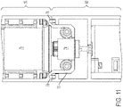
- the spice grinder attachment 20 shown separately in Fig. 21 , includes a reduction gearbox housing 200, a spice selector 202 and the spice hopper 204.
- Fig. 22 shows the internal gear assembly of the grinder attachment 20.
- Power is delivered to the grinder attachment 20 through an attachment shaft 208 that extends from the reduction gearbox housing 200 and is connected to the drive shaft 74 of the powerhead motor 70.
- the gearbox housing 200 includes a reduction gearbox 206 that reduces the rotational speed of the powerhead motor before it's transferred to grinders 224 and 226.
- the reduction gearbox 206 outputs to a drive axle 210 that is connected to a pair of slip gears 212 and 214.
- the drive axle 210 is fixedly connected to a drive gear 211 which engages slip gears 212 and 214, with the slip gears connected to respective grinder gears 216 and 218.
- the grinder gear 216 is attached to an axle 220 and grinder gear 218 is attached to axle 222.
- Each axle 220 and 222 is attached to grinder 224 and 226, which grind the spices in the hopper 204.
- the slip gear 212 includes a top gear wheel 212a and a bottom gear wheel 212b.
- the bottom gear wheel 212b is rotatably connected to grinder gear 216.
- the top gear wheel 212a includes a series of ramps 230a facing a corresponding series of ramps 230b on the bottom gear wheel 212b.
- the ramps having matching inclined surfaces 232a and 232b so that when the top gear wheel 212a is rotated in the counter-clockwise direction, the inclined surfaces 232a and 232b ride up one another and force the top gear wheel 212a upward until the ramps 230a and 230b disengage. At this point, the top gear wheel 212a slips and rotates relative to the bottom gear wheel 212b. When the top gear wheel 212a and bottom gear wheel 212b slip, the bottom gear wheel does not rotate, and no rotational movement is transferred to the grinder 224.
- the drive gear 211, slip gears 212 and 214, and grinder gears 216 and 218 are enclosed in the spice selector 202 by a top housing 240 and a bottom housing 242 and a spice selector wheel 244.
- the spice selector wheel 244 is rotatable with respect to the top housing 240 and bottom housing 242 to select which spice is to be ground.
- the spice selector wheel 244 has a protrusion 246 that projects from the bottom of the wheel, as shown in Fig. 25 .
- the wheel 244 rotates so that the protrusion 246 sits over one of the slip gears 212 or 214, thus preventing one of the top gear wheel (212a or 214a) from separating from its corresponding bottom gear wheel (212b or 214b).
- the protrusion 246 sits over the right slip gear 214, preventing the top gear wheel 214a from separating from its corresponding bottom gear wheel 214b. Without this separation, the top gear wheel 214a transfers its rotation to the bottom gear wheel 214b and ultimately to the grinder 226.
- the spice selector 202 determines which one of the grinders 224 or 226 is operational at any time.
- This design allows one of the two spices to be selected without having to change the rotational direction of the motor.
- switching between two different grinders was done by reversing the rotation of the motor, thereby engaging one set of gears and disengaging from a second set.
- the present design eliminates the need to a have a reversible motor.
- the spice selector wheel 244 includes several curved slots 248a, 248b, 248c, and 248d to accommodate the various gear axles that pass through the wheel 244 (see Fig. 25 ).
- the slots allow for the wheel 244 to be rotated between its two positions without being interrupted by any of the axles.
- the wheel 244 also includes an indicator 262 to identify to the user which spice is selected and ribs 264 around its circumference to make it easier to grip.
- the spice hopper 204 is shown having a clear outer housing 250 that contains the two grinders 224 and 226. Each grinder is housed in a separate chamber 253a and 253b separated by a clear wall 252. Above the housing 250 and formed as part of the bottom gearbox housing 242, are a pair of doors 254 and 256 that allow materials to be added to each chamber 253a and 253b, respectively. Below the grinders 224 and 226 are thumbscrews 270 and 272 that adjust the grinders to control how fine or coarse the material is ground.
- Fig. 29 shows the right door 256 in the open position.
- the door 256 pivots about an axle 257 and includes a stop 258 to prevent the door from opening too much and tab 260 which provides a light interference to keep the door in place when closed.
- FIG. 30 Another example of an attachment that can be used with the powerhead 110 is a wine opener attachment 18 shown in Fig. 30 .
- the wine opener 18 has a free end with an opening that slides over the neck 304 of a bottle 302 and removes a cork 306.
- Figs. 31-33 show the wine opener 18 in more detail.
- the wine opener 18 has an outer clamshell housing 308 that holds a gearbox 310 and a bottle stop 312.
- An output shaft 316 extends out from the gearbox 310 and mates with the driveshaft 74 of the powerhead 110.
- a corkscrew 320 is connected to an output 311 of the gearbox 310.
- a spring 322 surrounds the corkscrew 320 and is set against the gearbox 310 at one end, and against a thrust bearing 324 at the other.
- the bottle stop 312 houses a bearing holder 314 which secures the thrust bearing 324.
- the gearbox 310 includes a set of gears (not shown) that reduces the rotational output of the powerhead so that the corkscrew 320 rotates at a lower speed than the powerhead motor. Also shown in Fig. 31 is a foil cutter 326 that clips onto the end of the wine opener 18. The foil cutter is a tool that helps to remove the foil that's typically wrapped around the top of the bottle and covering the cork and will be described in further detail below.
- Fig. 34 shows the working end of the wine opener 18 as it is initially placed against the wine bottle 302. As the neck of the bottle is inserted into the opening it engages an inclined surface 330 of the bottle stop 312, which helps to center the bottle within the wine opener.
- the opening 313 defined by the top end of inclined surface 330 is large enough to accommodate the cork 306, but not the bottle itself.
- Powerhead 110 is turned on and the corkscrew is spinning and pushed down into the cork.
- the bottle stop 312 is pushed upwardly within the housing 308 against the bias of the spring 322 until the bottle stop 312 is stopped by protrusion 322. This is shown in Fig. 35 .
- the wine opener can no longer push down over the top of the bottle because of bottle stop 312 abutting the protrusion 322. Therefore, as the corkscrew 320 embeds deeper into the cork 306, the cork 306 is pulled out of the bottle 304. See Fig. 36 .
- the cork 306 As the cork 306 is pulled out, it presses up against the bearing holder 314 (which is holding thrust bearing 324) and moves upward against the spring 322, until it is fully removed from the bottle. See Fig. 37 . At this point the powerhead 110 can be turned off, and the bottle 304 pulled out of the wine opener 18. However, the cork 306 remains on the corkscrew 320.
- a latching system could be added to the opener to hold the spring 324 in its compressed state and contain the cork 306 within the wine opener until the user is ready to release the latch and allow the cork 306 to be unwound from the corkscrew 320.
- One of the advantages of the present wine opener 18 is that it allows for the cork 306 to be removed through the use of the spring 322 rather than reversing the rotation of the motor.
- the foil cutter 326 is explained in further detail.
- the foil cutter 326 is used to remove foil that is normally wrapped around the cork of a wine bottle.
- Fig. 40 shows the top of the foil cutter 326 having an a slit 334 that ends in an aperture 336.
- the slit 334 and aperture 336 divide the cutter into two halves 340a and 340b that can be biased into an open and closed position.
- Fig. 42 shows the bottom of the foil cutter having four posts 338 that hold two cutting blades 340 and 342.
- the foil cutter 326 is placed over the foil on a bottle and the two halves 340a and 340b are squeezed together to bring the two halves 340a and 340b together.
- the blades 340 and 342 are positioned so that they gently cut into the foil without damaging the bottle itself. The foil can then be removed from the bottle.
- the top of the foil cutter 326 includes tabs 344 that when squeezed together fit within a ledge of the housing 308 of the wine opener. This provides a convenient and easy storage location for the foil cutter 326.
Abstract
Description
- This application is directed to a system of hand-held kitchen appliances having a single powerhead capable of being attached to a variety of kitchen appliances. Examples of such attachments include, but are not limited to a blender, a whisker, a wine opener, a can opener, and a spice grinder.
- This section provides background information related to the present disclosure which is not necessarily prior art.
- Modular hand-held kitchen appliances are known in the art. These products are typically built around an immersion blender as the main product. The products then include several simple attachments, such as a whisk or milk frother, to provide additional functions to the consumer. While these added attachments provide increased convenience to the consumer, the lack of other attachments and versatility prevent them from being a complete, modular, kitchen multitool.
- Therefore, a modular kitchen multitool of the present invention aims to provide a powered solution to a wide variety of kitchen tasks beyond what is currently available. These attachments go beyond simple mixing and blending and extend to other areas of the kitchen such as spice grinding and wine opening. In addition to the variety of attachments, the present multitool is battery powered to give consumers added convenience as they work around the kitchen.
- In accordance with one aspect, the multitool includes a powerhead having a motor and rechargeable battery capable of powering a variety of different attachments. In a first embodiment of the powerhead, the rotational direction of the motor can be reversed and its speed changed to provide operational flexibility for the attachments. A quick release mechanism provides for quick and easy locking of the different attachments and a sensor identifies the attachment to automatically adjust the operational characteristics.
- In an embodiment of the powerhead, the motor reverse and speed change features are removed to provide a simpler and more cost effective design. With this powerhead, the attachment itself incorporates any desired features needed for operation.
- In another aspect, a dual spice grinder attachment is disclosed that is capable of use with the powerhead. The spice grinder includes two separate chambers for holding two different spices. The grinder includes a gearing mechanism that allows for the selection of one of the two spices to be ground, without having to reverse the direction of the motor. This is different from existing dual spice grinder which normally reverse the motor direction to switch between the two spices.
- In another aspect, there is provided a modular kitchen appliance, comprising: a powerhead having motor with a drive shaft; a grinder attachment removably attached to the powerhead, the grinder attachment having an attachment shaft that's connected to the drive shaft of the motor; the attachment shaft connected to a drive axle operatively connected to a first slip gear and a second slip gear; the first slip gear connected to a first grinder and the second slip gear connected to a second grinder; a hopper capable of holding two different materials for grinding; wherein in a first mode of operation, the first slip gear transfer power to the first grinder and the second gear does not transfer power to the second grinder, and in a second mode of operation the second slip gear transfer power to the second grinder and the first slip gear does not transfer power to the first grinder.
- The first and second slip gears may each have a top gear wheel and a bottom gear wheel that are selectively able to rotate relative to each other.
- The top gear wheel and bottom gear wheel of each of the first and second slip gears may have ramps that separate the top gear wheel from the bottom gear wheel to allow them to rotate relative to each other.
- The modular kitchen appliance may further comprise a spice selector that is movable over one of the first slip gear or second slip gear to prevent the top gear wheel from separating from the bottom gear wheel.
- The motor may rotate in the same direction in the first and second mode of operation.
- In another aspect, there is provided a method of grinding comprising the steps of providing a modular kitchen appliance with a powerhead having motor with and output shaft; attaching a grinder attachment to the powerhead, the grinder attachment having an attachment shaft that's connected to the drive shaft of the motor, the attachment shaft connected to a drive axle operatively connected to a first slip gear and a second slip gear, the first slip gear connected to a first grinder and the second slip gear connected to a second grinder; loading material to be ground into a hopper on the grinder attachment, the hopper capable of holding two different materials for grinding; operating the grinder attachment in a first mode, wherein the first slip gear transfer power to the first grinder and the second gear does not transfer power to the second grinder.
- The method may further comprise the step of operating the grinder in a second mode wherein the second slip gear transfer power to the second grinder and the first slip gear does not transfer power to the first grinder.
- The motor may rotate in the same direction in both the first mode of operation and the second mode of operation.
- The first and second slip gears may each have a top gear wheel and a bottom gear wheel that are selectively able to rotate relative to each other, wherein the top gear wheel and bottom gear wheel have ramps that separate the top gear wheel from the bottom gear wheel to allow them to rotate relative to each other; and the method may further comprise the step of moving a spice selector over one of the first slip gear or second slip gear to prevent the top gear wheel from separating from the bottom gear wheel.
- In yet another aspect, a wine opener attachment is disclosed that removes a cork from a bottle, and then automatically ejects the cork from the opener. The wine opener includes a spring that is compressed as the cork is removed from the bottle. After the cork is fully removed, the force of the spring pushes the cork so it unwinds off the corkscrew. This is in contrast to typical wine openers that operate the motor in a first direction to drive the corkscrew into the cork, and then reverse the motor to unwind the cork off the corkscrew.
- In an aspect, there is provided a modular kitchen appliance, comprising: a powerhead having motor with a drive shaft; a wine opener attachment removably attached to the powerhead, the wine opener attachment having an output shaft connected to the drive shaft of the motor, and a bottle stop for enclosing a bottle and a cork to be removed from the bottle, a spring and a corkscrew; wherein as the corkscrew is driven into the cork, the cork is removed from the bottle and compresses the spring, and upon the cork being fully removed from the bottle, the spring pushes on the cork to automatically remove the cork from the corkscrew.
- The modular kitchen appliance may further comprise a gearbox to reduce the rotational speed of the motor, the gearbox being connected to the corkscrew.
- The modular kitchen appliance may further comprise a thrust bearing positioned at one end of the spring, and the cork contacts the thrust bearing to compress the spring.
- The spring may be a helical spring surrounding the corkscrew.
- Further areas of applicability will become apparent from the description provided herein. The description and specific examples in this application are intended for purposes of illustration only and are not intended to limit the scope of the present disclosure.
- Further features and advantages of the present invention will be better understood by reference to the following description, which is given by way of example and in association with the accompanying drawings, in which:
-
Fig. 1 shows a powerhead with various attachments; -
Fig. 2 is a top view of the powerhead; -
Fig. 3 is a bottom view of the powerhead; -
Fig. 4 is a view of a charging port on the powerhead; -
Figs. 5 ,5A ,5B and6 show a first embodiment of a charger; -
Fig. 7 is a rear view of the powerhead; -
Figs. 8 ,8A and9 show a second embodiment of a charger; -
Fig. 10 is an interior view of the powerhead; -
Figs. 11-13 show a sensor assembly for the powerhead and attachments; -
Fig. 14 shows the attachment being secured to a powerhead; -
Figs. 15-17 show a locking mechanism for the powerhead and attachment; -
Figs. 18 and19 show a second embodiment of the powerhead; -
Figs. 20 and 21 show a grinder attachment on the powerhead; -
Figs. 22-24 show a gearing mechanism for the grinder attachment; -
Figs 25 and 26 show a spice selector for the grinder attachment; -
Fig. 27 is a cut-away view of the gearing mechanism; -
Fig. 28 is a cut away view of the spice hopper; -
Fig. 29 shows the door of the spice hopper; -
Fig. 30 shows a wine opener attachment and powerhead; -
Fig. 31 is a cut-away view of the wine opener attachment; -
Fig. 32 shows the internal components of the wine opener attachment; -
Fig. 33 is an exploded view ofFig. 32 ; -
Figs. 34-39 show various stages of the operation of the wine opener attachment; and -
Figs. 40-42 show a foil cutter used with the wine opener attachment. -
Fig. 1 shows the modular kitchen appliance system of the present invention. The system comprises apowerhead 10 that operates various kitchen appliance attachments that are selectively attached to the powerhead. Several examples of attachments are shown, such as animmersion blender 12,whisk 14,milk frother 16,wine opener 18,spice grinder 20 andcan opener 22. These examples are not exclusive, and other attachments not shown are within the scope of the invention. -
Figs 2 and 3 show thepowerhead 10 in more detail. The powerhead comprises ahousing 11 that enclose various components such as amotor 70 and a battery 72 (seeFig. 10 ). Thehousing 11 has aforward end 13, onto which the attachments are secured, and arearward end 15. -
Fig. 2 shows a top portion of thepowerhead 10 having aprimary switch 24 for turning the powerhead on and off. Asecond safety switch 26 is adjacent theprimary switch 24 and must be pressed simultaneously to power the motor.Fig. 3 shows a bottom of thepowerhead 10 having a chargingport 30 for charging the battery and a thirdreverse switch 28 that can reverse the rotational direction of the motor. -
Fig. 4 shows the chargingport 30 having two charging pins orterminals 32 with ametal plate 34 therebetween. A charger 36 (seeFig. 5 ) is connected to the chargingport 30 and includes a charginghead 37 that connects to thepowerhead 10, and awall plug 42 for connecting to a wall outlet. -
Figs. 5A and 5B show thecharger head 37 with anovermold 39 surrounding acontact head 41. Theovermold 39 is formed from twopieces contact head 41. Thefront overmold 39A is formed to correspond to the outer contour of the powerhead at the chargingport 30 so a smooth fit is achieved.Fig. 5B shows thefront overmold 39A removed to better show thecontact head 41. -
Fig. 6 shows an end face of the charginghead 37. The charging head has twospring contacts 38 and amagnet 40. Themagnet 40 is attracted themetal plate 34 of the chargingport 30 to secure the engagement between the charging pins 32 and thecontacts 38. The charger 36 shown inFigs. 5 and6 show a compact charger for users who have limited space and wish to hide the charger in a cabinet or drawer. -
Figs. 8 ,8A and9 show an alternativecup style charger 50 for users with more space, allowing them to keep theirpowerhead 10 out in the open, for example on their countertop. Thecharger 50 is formed from two pieces, a base 60 (shown inFig. 9 ) and astantion 52 that's placed over the base. Thestantion 52 provides an upright support for holding thepowerhead 10 while charging and allows the user to easily insert and remove thepowerhead 10 when needed. Thestantion 52 includes an opening for securing and providing access to contacthead 41, with apower cord 42 extending out from thestantion 52. - Referring now to
Fig. 7 , a rear end of thepowerhead 10 is shown having arotatable cap 44. Thecap 44 can be rotated between two positions which controls the speed of themotor 70. Rotating thecap 44 to the left inFig. 7 slows the motor down, and rotating thecap 44 to the right increases the speed of the motor. - Referring now to
Fig. 10 , the inside of thepowerhead 10 is shown. Thehousing 11 holds the components of the powerhead, including themotor 70 and thebattery pack 72. Themotor 70 has adrive shaft 74 surrounded by anenclosure 76, which includes anopening 78 through which thedrive shaft 74 can engage with the various attachments. APCB 64 lies over thebattery pack 72 and receives signals from the various switches and sensors on the powerhead to control the operation of the motor. - The
battery pack 72 provides energy to themotor 70 using rechargeable cells. However, it should be understood that removable (either disposable or rechargeable) batteries or even an AC power cord could power the motor and still fall within the scope of the invention. Aswitch 66 electrically connects themotor 70 andbattery pack 72, and is actuated byswitch 24. - At least two
Hall sensors 78 are providedadjacent enclosure 76. TheHall sensors 78 are used to identify the attachment connected to thepowerhead 10 and adjust the powerheads operation accordingly. For example, a particular attachment may not need to reverse the motor or have multiple speed controls, and the Hall sensors would recognize the attachment and could disable those features. - Magnets are used on the attachment to signal to the Hall sensor what type of attachment is being used.
Figs. 11-13 show various examples, and in particularFig. 11 shows anattachment 80 with no magnets. TheHall sensors 78 detecting no magnet send a signal (or absence of a signal) to the PCB, which identifies the attachment and operates the powerhead in a first mode, whereby all the features of the powerhead are enabled. In other words, the powerhead motor can be reversed and/or its speed adjusted. -
Fig. 12 shows asecond attachment 82 having asingle magnet 84 that is positioned adjacent one of theHall sensors 78. TheHall sensor 78 detects themagnet 84, and then instructs the powerhead to operate in a second mode, where the speed selector is disabled, but the motor reversing feature is enabled. This second mode is activated when only one magnet is sensed, regardless which Hall sensor is triggered. -
Fig. 13 shows a third attachment having twomagnets 88 adjacent the twoHall sensor 78 when connected. BothHall sensors 78 detect the presence of the magnets and instruct the powerhead to operate in a third mode where both the speed selector and reversing feature are disabled. - In addition to the
Hall sensors 78, thePCB 64 receives inputs from theswitches cap 44 to control the motor and other operational characteristics of the powerhead. - Reference is now made to
Fig. 14 which shows thepowerhead 10 and ageneric attachment 90. Theattachment 90 can be any one of the attachments shown inFig. 1 , but is shown generically here to illustrate how the attachment is secured to thepowerhead 10. -
Fig. 15 shows thefront end 13 of thepowerhead 10. Theenclosure 76 surrounding themotor drive shaft 74 includes a lockingrail 92 and atab 94. Theattachment 90 has aninterior space 96 into which theenclosure 76 is inserted. Theattachment 90 includes afirst rib 98 and asecond rib 100 in a generally T-shaped configuration, projecting inwardly into theinterior space 96. - To secure the
attachment 90 to thepowerhead 10, theattachment 90 is moved onto thepowerhead 10 as shown by arrow 93 inFig. 14 . Therib 98 is positioned adjacent aslot 102 formed by therail 92, and then theattachment 90 is rotated. Therib 98 then slides into theslot 102. SeeFigs. 16 and 17 which shows the movement of theribs -
Fig. 15 shows therail 92 is generally L-shaped, where aleg portion 104 is slightly angled to create a larger opening for therib 98. Theangled leg 104 allows for therib 98 to more easily enter theslot 102 and also creates a cam surface that pulls theattachment 90 toward thepowerhead 10, creating a tighter and firmer connection between the two. - Additionally, when the
attachment 90 is rotated into its locked position, theother rib 100 slides overtab 94. Thetab 94 is flexible and includes abump 106 on its free end that's flexed as therib 100 slides over. Thetab 94 provides haptic feedback notifying the user that the attachment has been properly secured. Thetab 94 also functions to reduce the likelihood that theattachment 90 would inadvertently rotate out of the locked position. - A second set of
ribs rail 92 andtab 94 are positioned opposite the first set to provide a more secure connection between thepowerhead 10 andattachment 90. Although two sets are shown in the figures, any number ofribs 98/100 andrail 92tab 100 combinations could be used depending on how strong a connection is desired. - Now referring to
Figs. 18 and19 , an alternative embodiment of thepowerhead 110 is shown. Thepowerhead 110 is a simpler version of thepowerhead 10, with some features removed to reduce cost and complexity. Unless otherwise noted, thepowerhead 110 operates similarly topowerhead 10, including the how the attachments are connected to the powerhead as described above. For convenience, identical elements to those found onpowerhead 10 are given the same reference number here. - The
powerhead 110 includes aswitch 24 for turning the device on and off. A reverse side includes asafety switch 26 which must be depressed simultaneously with theswitch 24 for providing energy to the device. A chargingport 30 provides electricity to the internalrechargeable battery pack 72. Arear cap 44 is rotatable in both the clockwise and counterclockwise directions to control the speed of themotor 70. The front end of the powerhead includes anenclosure 76 identical the previous embodiment, and the locking mechanism for the attachment can be identical as well. Thepowerhead 110 further include a pair oflegs 112 prevent it from rolling around when lying on a flat surface. -
Fig. 20 shows the dualspice grinder attachment 20 secured to thepowerhead 110 of the present invention. The dual spice grinder includes ahopper 204 for holding two different spices (or other material to be ground) in separate chambers. The spices can be any food material, including salt, peppercorn, coffee beans, seeds, etc. - The
spice grinder attachment 20, shown separately inFig. 21 , includes areduction gearbox housing 200, aspice selector 202 and thespice hopper 204.Fig. 22 shows the internal gear assembly of thegrinder attachment 20. - Power is delivered to the
grinder attachment 20 through anattachment shaft 208 that extends from thereduction gearbox housing 200 and is connected to thedrive shaft 74 of thepowerhead motor 70. Thegearbox housing 200 includes areduction gearbox 206 that reduces the rotational speed of the powerhead motor before it's transferred togrinders - Referring now to
Figs. 22 and23 , thereduction gearbox 206 outputs to adrive axle 210 that is connected to a pair of slip gears 212 and 214. Thedrive axle 210 is fixedly connected to adrive gear 211 which engages slip gears 212 and 214, with the slip gears connected to respective grinder gears 216 and 218. Thegrinder gear 216 is attached to anaxle 220 andgrinder gear 218 is attached toaxle 222. Eachaxle grinder hopper 204. - Referring now to
Fig. 23 , the operation of the slip gears 212 and 214 is explained. Each slip gear functions in the same way, and so a description ofonly slip gear 212 is provided. Theslip gear 212 includes atop gear wheel 212a and abottom gear wheel 212b. Thebottom gear wheel 212b is rotatably connected togrinder gear 216. Thetop gear wheel 212a includes a series oframps 230a facing a corresponding series oframps 230b on thebottom gear wheel 212b. The ramps having matchinginclined surfaces top gear wheel 212a is rotated in the counter-clockwise direction, theinclined surfaces top gear wheel 212a upward until theramps top gear wheel 212a slips and rotates relative to thebottom gear wheel 212b. When thetop gear wheel 212a andbottom gear wheel 212b slip, the bottom gear wheel does not rotate, and no rotational movement is transferred to thegrinder 224. - Referring to
Fig. 24 , thedrive gear 211, slip gears 212 and 214, and grinder gears 216 and 218 are enclosed in thespice selector 202 by atop housing 240 and abottom housing 242 and aspice selector wheel 244. Thespice selector wheel 244 is rotatable with respect to thetop housing 240 andbottom housing 242 to select which spice is to be ground. - The
spice selector wheel 244 has aprotrusion 246 that projects from the bottom of the wheel, as shown inFig. 25 . Thewheel 244 rotates so that theprotrusion 246 sits over one of the slip gears 212 or 214, thus preventing one of the top gear wheel (212a or 214a) from separating from its corresponding bottom gear wheel (212b or 214b). As shown inFig. 26 and27 , theprotrusion 246 sits over theright slip gear 214, preventing thetop gear wheel 214a from separating from its correspondingbottom gear wheel 214b. Without this separation, thetop gear wheel 214a transfers its rotation to thebottom gear wheel 214b and ultimately to thegrinder 226. Depending on whichslip gear protrusion 246 sits over, thespice selector 202 determines which one of thegrinders - This design allows one of the two spices to be selected without having to change the rotational direction of the motor. In prior art grinders with two different spices, switching between two different grinders was done by reversing the rotation of the motor, thereby engaging one set of gears and disengaging from a second set. The present design eliminates the need to a have a reversible motor.
- The
spice selector wheel 244 includes severalcurved slots Fig. 25 ). The slots allow for thewheel 244 to be rotated between its two positions without being interrupted by any of the axles. Thewheel 244 also includes anindicator 262 to identify to the user which spice is selected andribs 264 around its circumference to make it easier to grip. - Now referring to
Fig. 28 , thespice hopper 204 is shown having a clearouter housing 250 that contains the twogrinders separate chamber clear wall 252. Above thehousing 250 and formed as part of thebottom gearbox housing 242, are a pair ofdoors chamber grinders thumbscrews -
Fig. 29 shows theright door 256 in the open position. Thedoor 256 pivots about anaxle 257 and includes astop 258 to prevent the door from opening too much andtab 260 which provides a light interference to keep the door in place when closed. - Another example of an attachment that can be used with the
powerhead 110 is awine opener attachment 18 shown inFig. 30 . Thewine opener 18 has a free end with an opening that slides over theneck 304 of abottle 302 and removes acork 306. -
Figs. 31-33 show thewine opener 18 in more detail. Thewine opener 18 has anouter clamshell housing 308 that holds agearbox 310 and abottle stop 312. Anoutput shaft 316 extends out from thegearbox 310 and mates with thedriveshaft 74 of thepowerhead 110. Acorkscrew 320 is connected to anoutput 311 of thegearbox 310. Aspring 322 surrounds thecorkscrew 320 and is set against thegearbox 310 at one end, and against athrust bearing 324 at the other. As can be seen fromFigs. 31 and33 , the bottle stop 312 houses a bearingholder 314 which secures thethrust bearing 324. - The
gearbox 310 includes a set of gears (not shown) that reduces the rotational output of the powerhead so that thecorkscrew 320 rotates at a lower speed than the powerhead motor. Also shown inFig. 31 is afoil cutter 326 that clips onto the end of thewine opener 18. The foil cutter is a tool that helps to remove the foil that's typically wrapped around the top of the bottle and covering the cork and will be described in further detail below. - Now referring to
Figs. 34-39 , the operation of the wine opener will be explained.Fig. 34 shows the working end of thewine opener 18 as it is initially placed against thewine bottle 302. As the neck of the bottle is inserted into the opening it engages aninclined surface 330 of thebottle stop 312, which helps to center the bottle within the wine opener. Theopening 313 defined by the top end ofinclined surface 330 is large enough to accommodate thecork 306, but not the bottle itself. -
Powerhead 110 is turned on and the corkscrew is spinning and pushed down into the cork. As the wine opener is pressed down, thebottle stop 312 is pushed upwardly within thehousing 308 against the bias of thespring 322 until thebottle stop 312 is stopped byprotrusion 322. This is shown inFig. 35 . At this point, the wine opener can no longer push down over the top of the bottle because ofbottle stop 312 abutting theprotrusion 322. Therefore, as thecorkscrew 320 embeds deeper into thecork 306, thecork 306 is pulled out of thebottle 304. SeeFig. 36 . - As the
cork 306 is pulled out, it presses up against the bearing holder 314 (which is holding thrust bearing 324) and moves upward against thespring 322, until it is fully removed from the bottle. SeeFig. 37 . At this point thepowerhead 110 can be turned off, and thebottle 304 pulled out of thewine opener 18. However, thecork 306 remains on thecorkscrew 320. - The fully
compressed spring 322 now pushes down on thecork 306 to unwind it from thecorkscrew 320.Fig. 38 shows the cork partially unwound andFig. 39 shows the cork fully unwound from the corkscrew. Obviously, the downward force of the spring must be strong enough to overcome the frictional forces maintaining thecork 306 on thecorkscrew 320. The unwinding of thecork 306 is facilitated because both thethrust bearing 324 and thebearing holder 314 are freely rotatable within thebottle stop 312, allowing thecork 306 to rotate as it's unwound. In a further embodiment of the invention, a latching system could be added to the opener to hold thespring 324 in its compressed state and contain thecork 306 within the wine opener until the user is ready to release the latch and allow thecork 306 to be unwound from thecorkscrew 320. - One of the advantages of the
present wine opener 18 is that it allows for thecork 306 to be removed through the use of thespring 322 rather than reversing the rotation of the motor. - Now referring to
Figs. 40-42 , thefoil cutter 326 is explained in further detail. Thefoil cutter 326 is used to remove foil that is normally wrapped around the cork of a wine bottle.Fig. 40 shows the top of thefoil cutter 326 having an aslit 334 that ends in anaperture 336. Theslit 334 andaperture 336 divide the cutter into twohalves Fig. 42 shows the bottom of the foil cutter having fourposts 338 that hold two cuttingblades - The
foil cutter 326 is placed over the foil on a bottle and the twohalves halves blades - Additionally, as shown in
Fig. 30 ,40 and 41 , the top of thefoil cutter 326 includestabs 344 that when squeezed together fit within a ledge of thehousing 308 of the wine opener. This provides a convenient and easy storage location for thefoil cutter 326. - The foregoing description of the embodiments has been provided for purposes of illustration and description. It is not intended to be exhaustive or to limit the disclosure. Individual elements or features of a particular embodiment are generally not limited to that particular embodiment, but, where applicable, are interchangeable and can be used in a selected embodiment, even if not specifically shown or described. The same may also be varied in many ways. Such variations are not to be regarded as a departure from the disclosure, and all such modifications are intended to be included within the scope of the disclosure
Claims (13)
- A modular kitchen appliance, comprising:a powerhead having motor with a drive shaft;a grinder attachment removably attached to the powerhead, the grinder attachment having an attachment shaft that's connected to the drive shaft of the motor;the attachment shaft connected to a drive axle operatively connected to a first slip gear and a second slip gear;the first slip gear connected to a first grinder and the second slip gear connected to a second grinder;a hopper capable of holding two different materials for grinding;wherein in a first mode of operation, the first slip gear transfer power to the first grinder and the second gear does not transfer power to the second grinder, and in a second mode of operation the second slip gear transfer power to the second grinder and the first slip gear does not transfer power to the first grinder.
- The modular kitchen appliance according to claim 1, wherein the first and second slip gears each have a top gear wheel and a bottom gear wheel that are selectively able to rotate relative to each other.
- The modular kitchen appliance according to claim 2, wherein the top gear wheel and bottom gear wheel of each of the first and second slip gears have ramps that separate the top gear wheel from the bottom gear wheel to allow them to rotate relative to each other.
- The modular kitchen appliance according to claim 2 or 3, further comprising a spice selector that is movable over one of the first slip gear or second slip gear to prevent the top gear wheel from separating from the bottom gear wheel.
- The modular kitchen appliance according to any preceding claim, wherein the motor rotates in the same direction in the first and second mode of operation.
- A method of grinding comprising the steps of providing a modular kitchen appliance with a powerhead having motor with and output shaft;attaching a grinder attachment to the powerhead, the grinder attachment having an attachment shaft that's connected to the drive shaft of the motor, the attachment shaft connected to a drive axle operatively connected to a first slip gear and a second slip gear, the first slip gear connected to a first grinder and the second slip gear connected to a second grinder;loading material to be ground into a hopper on the grinder attachment, the hopper capable of holding two different materials for grinding;operating the grinder attachment in a first mode, wherein the first slip gear transfers power to the first grinder and the second gear does not transfer power to the second grinder.
- The method of grinding according to claim 6, further comprising the step of operating the grinder in a second mode wherein the second slip gear transfer power to the second grinder and the first slip gear does not transfer power to the first grinder.
- The method of grinding according to claim 6 or 7, wherein the motor rotates in the same direction in both the first mode of operation and the second mode of operation.
- The method of grinding according to claim 8, wherein the first and second slip gears each have a top gear wheel and a bottom gear wheel that are selectively able to rotate relative to each other, wherein the top gear wheel and bottom gear wheel have ramps that separate the top gear wheel from the bottom gear wheel to allow them to rotate relative to each other; and
further comprising the step of moving a spice selector over one of the first slip gear or second slip gear to prevent the top gear wheel from separating from the bottom gear wheel. - A modular kitchen appliance, comprising:a powerhead having motor with a drive shaft;a wine opener attachment removably attached to the powerhead, the wine opener attachment having an output shaft connected to the drive shaft of the motor, and a bottle stop for enclosing a bottle and a cork to be removed from the bottle, a spring and a corkscrew;wherein as the corkscrew is driven into the cork, the cork is removed from the bottle and compresses the spring, and upon the cork being fully removed from the bottle, the spring pushes on the cork to automatically remove the cork from the corkscrew.
- The modular kitchen appliance of claim 10, further comprising a gearbox to reduce the rotational speed of the motor, the gearbox being connected to the corkscrew.
- The modular kitchen appliance of claim 10 or 11, further comprising a thrust bearing positioned at one end of the spring, and the cork contacts the thrust bearing to compress the spring.
- The modular kitchen appliance of claim 10, 11 or 12, wherein the spring is a helical spring surrounding the corkscrew.
Applications Claiming Priority (1)
| Application Number | Priority Date | Filing Date | Title |
|---|---|---|---|
| US17/167,150 US20220240723A1 (en) | 2021-02-04 | 2021-02-04 | Modular hand-held kitchen applicance |
Publications (2)
| Publication Number | Publication Date |
|---|---|
| EP4049564A2 true EP4049564A2 (en) | 2022-08-31 |
| EP4049564A3 EP4049564A3 (en) | 2022-09-21 |
Family
ID=80122285
Family Applications (1)
| Application Number | Title | Priority Date | Filing Date |
|---|---|---|---|
| EP22153818.4A Pending EP4049564A3 (en) | 2021-02-04 | 2022-01-28 | Modular hand-held kitchen applicance |
Country Status (2)
| Country | Link |
|---|---|
| US (1) | US20220240723A1 (en) |
| EP (1) | EP4049564A3 (en) |
Families Citing this family (2)
| Publication number | Priority date | Publication date | Assignee | Title |
|---|---|---|---|---|
| USD998411S1 (en) * | 2021-06-30 | 2023-09-12 | Zhuhai Royal Electric Appliance Co., Ltd | Food blender |
| USD1005073S1 (en) * | 2021-09-02 | 2023-11-21 | Dongguan Hehe Plastic Electronics Co., Ltd. | Electric wine opener |
Family Cites Families (11)
| Publication number | Priority date | Publication date | Assignee | Title |
|---|---|---|---|---|
| CA931373A (en) * | 1971-02-22 | 1973-08-07 | L. Messiha Habib | Automatic bottle opener |
| US3827641A (en) * | 1972-09-29 | 1974-08-06 | Gullaskrufs Glasbruks Ab | Multi-purpose grinding mill |
| IT209821Z2 (en) * | 1987-01-15 | 1988-11-04 | Tedioli Pier Giorgio | ELECTRIC MACHINE APPARATUS, FOR MILLING PEPPER OR SALT. |
| US5724869A (en) * | 1995-06-08 | 1998-03-10 | May; Robert A. | Automatic cork remover |
| DE202005000438U1 (en) * | 2005-01-13 | 2005-10-06 | Richter, Siegfried | Electric cork screw has threaded spindle connected to mains or battery operated motor and with spring tensioning to force out cork |
| ATE476901T1 (en) * | 2006-07-13 | 2010-08-15 | Pi Design Ag | COMBINED SALT AND PEPPER MILL |
| FR2953208B1 (en) * | 2009-11-27 | 2011-11-18 | Jensen Ind Ltd | MULTI-FUNCTION HOUSEHOLD APPLIANCE COMPRISING A POWER-FREE MOTORIZED HANDLE AND A SET OF INTERCHANGEABLE INSTRUMENTS |
| US8757529B2 (en) * | 2011-03-23 | 2014-06-24 | Samson Bright Industrial Company Limited | Condiment grinder |
| US9516975B2 (en) * | 2014-04-18 | 2016-12-13 | King's Flair Development Ltd. | Condiment mill |
| US9693657B2 (en) * | 2015-01-22 | 2017-07-04 | Helen Of Troy Limited | Spice mill |
| US10328562B2 (en) * | 2016-12-23 | 2019-06-25 | Tti (Macao Commercial Offshore) Limited | Handheld kitchen appliance assembly |
-
2021
- 2021-02-04 US US17/167,150 patent/US20220240723A1/en active Pending
-
2022
- 2022-01-28 EP EP22153818.4A patent/EP4049564A3/en active Pending
Also Published As
| Publication number | Publication date |
|---|---|
| US20220240723A1 (en) | 2022-08-04 |
| EP4049564A3 (en) | 2022-09-21 |
Similar Documents
| Publication | Publication Date | Title |
|---|---|---|
| EP4049564A2 (en) | Modular hand-held kitchen applicance | |
| US20090032627A1 (en) | Spice Grinder | |
| CA2909262C (en) | Portable electric and hand operated herb grinder | |
| US10813499B2 (en) | Grinder | |
| US4856718A (en) | Food processor and food cutting devices therefor | |
| EP3338604B1 (en) | Handheld kitchen appliance assembly | |
| US7520453B2 (en) | Safety actuator for a food processor having a visual indication | |
| US11903524B2 (en) | Motor driven food processing system | |
| US20040129809A1 (en) | Modular appliance system | |
| CA3082176C (en) | Spiralizer mixer attachment | |
| US6377022B1 (en) | Rechargeable coffee bean and spice mill | |
| WO2008047106A1 (en) | A food processor | |
| US5685501A (en) | Portable electric spice mill | |
| KR20170035759A (en) | Food processing machine comprising a structure for transferring a rotating force | |
| US20240090703A1 (en) | Cordless blending appliance | |
| CN115209768A (en) | Semi-automatic machine for comminuting and then collecting external frozen food products for subsequent use | |
| KR20170035758A (en) | Food processing machine for controlling an operation mode using magnetic | |
| US20230277004A1 (en) | Cordless food processor | |
| KR20180119855A (en) | Food processing machine comprising a structure for transferring a rotating force | |
| US20240090706A1 (en) | Portable blade grinder | |
| EP0721757B1 (en) | Motorized vegetable mill | |
| CN209202919U (en) | cooking equipment | |
| CN219613724U (en) | Kitchen hand-held device and fittings | |
| US20190022882A1 (en) | Portable electric rotary slicer | |
| CN117717280A (en) | Portable blade type grinder |
Legal Events
| Date | Code | Title | Description |
|---|---|---|---|
| PUAI | Public reference made under article 153(3) epc to a published international application that has entered the european phase |
Free format text: ORIGINAL CODE: 0009012 |
|
| STAA | Information on the status of an ep patent application or granted ep patent |
Free format text: STATUS: THE APPLICATION HAS BEEN PUBLISHED |
|
| PUAL | Search report despatched |
Free format text: ORIGINAL CODE: 0009013 |
|
| AK | Designated contracting states |
Kind code of ref document: A2 Designated state(s): AL AT BE BG CH CY CZ DE DK EE ES FI FR GB GR HR HU IE IS IT LI LT LU LV MC MK MT NL NO PL PT RO RS SE SI SK SM TR |
|
| AK | Designated contracting states |
Kind code of ref document: A3 Designated state(s): AL AT BE BG CH CY CZ DE DK EE ES FI FR GB GR HR HU IE IS IT LI LT LU LV MC MK MT NL NO PL PT RO RS SE SI SK SM TR |
|
| RIC1 | Information provided on ipc code assigned before grant |
Ipc: B67B 7/04 20060101ALI20220816BHEP Ipc: A47J 42/46 20060101ALI20220816BHEP Ipc: A47J 43/06 20060101AFI20220816BHEP |
|
| STAA | Information on the status of an ep patent application or granted ep patent |
Free format text: STATUS: REQUEST FOR EXAMINATION WAS MADE |
|
| 17P | Request for examination filed |
Effective date: 20230315 |
|
| RBV | Designated contracting states (corrected) |
Designated state(s): AL AT BE BG CH CY CZ DE DK EE ES FI FR GB GR HR HU IE IS IT LI LT LU LV MC MK MT NL NO PL PT RO RS SE SI SK SM TR |
|
| STAA | Information on the status of an ep patent application or granted ep patent |
Free format text: STATUS: EXAMINATION IS IN PROGRESS |
|
| 17Q | First examination report despatched |
Effective date: 20230626 |
|
| GRAP | Despatch of communication of intention to grant a patent |
Free format text: ORIGINAL CODE: EPIDOSNIGR1 |
|
| STAA | Information on the status of an ep patent application or granted ep patent |
Free format text: STATUS: GRANT OF PATENT IS INTENDED |
|
| INTG | Intention to grant announced |
Effective date: 20231129 |
|
| RIN1 | Information on inventor provided before grant (corrected) |
Inventor name: LANGFORD, DANIEL Inventor name: CROSS, ANDREW Inventor name: BASKAR, ASHOK Inventor name: NOHE, KENDALL Inventor name: DOYLE, MICHAEL C. Inventor name: LANDIS, THOMAS Inventor name: SERGYEYENKO, OLEKSIY |
|
| GRAJ | Information related to disapproval of communication of intention to grant by the applicant or resumption of examination proceedings by the epo deleted |
Free format text: ORIGINAL CODE: EPIDOSDIGR1 |
|
| STAA | Information on the status of an ep patent application or granted ep patent |
Free format text: STATUS: EXAMINATION IS IN PROGRESS |
|
| GRAP | Despatch of communication of intention to grant a patent |
Free format text: ORIGINAL CODE: EPIDOSNIGR1 |
|
| STAA | Information on the status of an ep patent application or granted ep patent |
Free format text: STATUS: GRANT OF PATENT IS INTENDED |