EP4049474B1 - Kanalqualitätsvorhersage in einem drahtlosen netzwerk in einer industriellen umgebung unter verwendung eines prädiktiven modells und eines neuronalen netzwerks - Google Patents
Kanalqualitätsvorhersage in einem drahtlosen netzwerk in einer industriellen umgebung unter verwendung eines prädiktiven modells und eines neuronalen netzwerks Download PDFInfo
- Publication number
- EP4049474B1 EP4049474B1 EP19791231.4A EP19791231A EP4049474B1 EP 4049474 B1 EP4049474 B1 EP 4049474B1 EP 19791231 A EP19791231 A EP 19791231A EP 4049474 B1 EP4049474 B1 EP 4049474B1
- Authority
- EP
- European Patent Office
- Prior art keywords
- channel quality
- node
- periodic pattern
- predictive model
- information relating
- Prior art date
- Legal status (The legal status is an assumption and is not a legal conclusion. Google has not performed a legal analysis and makes no representation as to the accuracy of the status listed.)
- Active
Links
Images


Classifications
-
- H—ELECTRICITY
- H04—ELECTRIC COMMUNICATION TECHNIQUE
- H04B—TRANSMISSION
- H04B17/00—Monitoring; Testing
- H04B17/30—Monitoring; Testing of propagation channels
- H04B17/391—Modelling the propagation channel
- H04B17/3913—Predictive models, e.g. based on neural network models
-
- H—ELECTRICITY
- H04—ELECTRIC COMMUNICATION TECHNIQUE
- H04B—TRANSMISSION
- H04B17/00—Monitoring; Testing
- H04B17/30—Monitoring; Testing of propagation channels
- H04B17/373—Predicting channel quality or other radio frequency [RF] parameters
-
- H—ELECTRICITY
- H04—ELECTRIC COMMUNICATION TECHNIQUE
- H04W—WIRELESS COMMUNICATION NETWORKS
- H04W16/00—Network planning, e.g. coverage or traffic planning tools; Network deployment, e.g. resource partitioning or cells structures
- H04W16/18—Network planning tools
- H04W16/20—Network planning tools for indoor coverage or short range network deployment
-
- H—ELECTRICITY
- H04—ELECTRIC COMMUNICATION TECHNIQUE
- H04W—WIRELESS COMMUNICATION NETWORKS
- H04W16/00—Network planning, e.g. coverage or traffic planning tools; Network deployment, e.g. resource partitioning or cells structures
- H04W16/22—Traffic simulation tools or models
- H04W16/225—Traffic simulation tools or models for indoor or short range network
-
- H—ELECTRICITY
- H04—ELECTRIC COMMUNICATION TECHNIQUE
- H04W—WIRELESS COMMUNICATION NETWORKS
- H04W24/00—Supervisory, monitoring or testing arrangements
- H04W24/02—Arrangements for optimising operational condition
-
- H—ELECTRICITY
- H04—ELECTRIC COMMUNICATION TECHNIQUE
- H04W—WIRELESS COMMUNICATION NETWORKS
- H04W24/00—Supervisory, monitoring or testing arrangements
- H04W24/04—Arrangements for maintaining operational condition
Definitions
- Embodiments of the disclosure relate to wireless communications, and particularly to methods, apparatus and machine-readable media for predicting channel quality in a wireless network.
- a receiving device such as a wireless device (in downlink) or a radio access network node (in uplink) senses the radio channel and sends feedback on the channel quality to the transmitting device (e.g., a radio access network node in downlink, or a wireless device in uplink).
- the receiving device may transmit a channel quality indicator (CQI) report comprising an indication of the quality of the channel.
- CQI channel quality indicator
- the transmitting device then adapts the transmission scheme (e.g., modulation and coding scheme) according to the feedback for a following transmission to the receiving device. For example, if the channel gain decreases or interference increases, the coding rate may be increased and/or the modulation depth may be decreased, so that the transmission is more robust to the poor radio conditions and more likely to be successfully received. This process is called link adaptation.
- the CQl comprises a four-bit index taking one of 15 values, indicative of the channel quality as measured by the wireless device.
- the methods by which the CQl is determined in the wireless device have not been fixed in telecommunication standards, and are rather considered a matter for implementation by equipment manufacturers.
- the efficiency of link adaptation depends critically on the accuracy with which the channel quality is measured. If the channel quality is underestimated, the link adaptation becomes too conservative and the channel is under-utilized. If the channel quality is overestimated, the link adaptation becomes too ambitious and retransmissions, delays and reduced throughput may result. In either case, the operation point of the wireless channel is non-optimal.
- the delay introduced by the mechanism for feeding back channel quality e.g., time to perform measurements, determine the CQI, formulate the CQI report, and transmit the CQI report to the transmitting device
- the reported channel quality may be obsolete, or at least inaccurate, by the time the transmitting device receives and acts upon it.
- US patent publication no 2005/0227697 attempts to solve this problem by providing a method in which the base station uses the reported channel quality data to predict the channel quality experienced by a mobile device at the actual time when a downlink transmission takes place.
- the prediction method in US 2005/0227697 uses a weighted average of previously reported channel quality values to predict the future value of channel quality.
- machine learning techniques have been applied to the problem of channel prediction, such as in a technical paper by Liao et al ("The Rayleigh Fading Channel Prediction via Deep Learning", Wireless Communications and Mobile Computing, July 2018, pages 1-11 ).
- channel prediction remains a challenging problem.
- the large number of variables experienced by a wireless device at any one time mean that the channel quality can vary almost randomly from one time instance to the next.
- control of such machines 104 may also be wireless.
- control or instruction signals may be transmitted to the controllers for such machines 104, instructing them to perform one or more required tasks (possibly based on the data from the sensors).
- control signals will typically require extremely low latency and high reliability, and indeed the Third Generation Partnership Project (3GPP) is working on mechanisms for delivering a class of traffic known as ultra-reliable low-latency communications (URLLC).
- 3GPP Third Generation Partnership Project
- the wireless devices 106 are located within the interior of the environment 110.
- the wireless devices 106 may alternatively be termed user equipments (UEs), mobile stations (STAs), etc.
- Figure 1 shows two possible locations for the wireless devices: a first wireless device 106a which is coupled to a machine 104, but which is not located on a moving part thereof; and a second wireless device 106b which is coupled to a machine 104 and is located on a moving part thereof.
- the first wireless device 106a may be located in a base of the machine 104 as illustrated, or at some other location which is physically close enough to the machine 104 to enable control signals or instructions to be relayed from the first wireless device 106a to control circuitry of the machine 104 while meeting any latency requirements. It will be understood by those skilled in the art that only a single wireless device is required for implementation of the concepts described herein.
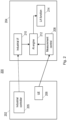
- FIG 2 is a schematic diagram of a wireless system 200 according to embodiments of the disclosure.
- the system 200 may be embodied in the system 100 described above with respect to Figure 1 .
- the system 200 comprises a machine 202 and a radio access network node 204.
- the machine 202 may correspond to the machine 104, while the radio access network node 204 may correspond to either radio access network node 102 shown in Figure 1 .
- the machine 202 comprises a wireless device 206 (such as either wireless device 106 described above with respect to Figure 1 ) and an industrial controller 205.
- the radio access network node 204 comprises a measurement control function 208, an industrial interface 210, an artificial intelligence (AI) engine 212 and a link adaptation function 214.
- AI artificial intelligence
- Embodiments of the disclosure relate to link adaptation for radio transmissions between the wireless device 206 and the radio access network node 204. As part of that process, the wireless device 206 performs measurements to assess the quality of the radio channel between the wireless device 206 and the radio access network node 204.
- the measurements may be performed on one or more known reference signals or reference symbols transmitted by the radio access network node 204.
- Channel equalization is performed on these received reference signals or symbols, based on the known transmitted reference signals or symbols, to recover the radio channel between the wireless device 206 and the radio access network node 204.
- Information relating to the channel quality is then reported back by the wireless device 206 to the radio access network node 204.
- the information may comprise a channel quality indicator (CQI), e.g., an index value within a particular range of values indicating the relative quality of the channel.
- CQI channel quality indicator
- the CQI index in LTE is a four-bit index and can take one of 15 different values ranging from 1 (indicating very poor channel quality) to 15 (indicating very good channel quality); the 0 value is reserved to indicate that the wireless device is out of range of the radio access network node.
- This format may be re-used by the wireless device 206, or different formats may be used.
- the predictive model may be trained to predict a channel quality based on reported time-series data for the channel quality.
- the predictive model may be trained to receive, as input, n data samples of the channel quality arranged in time-series order (where n is an integer, and will typically be significantly higher than 1); and to output a prediction for the (n + k)th data value.
- k is an integer, and may be equal to 1 (e.g., where the predictive model outputs an immediately succeeding value for the channel quality) or a larger value (e.g., wherein the predictive model outputs a value for a time period which is further in the future).
- the number of data samples n may be selected so as to correspond to a single or a whole number of cycles of the periodic pattern.
- the predictive model may be implemented in the machine 202 or the wireless device 206 itself.
- the wireless device predicts a future channel quality, based on a measured channel quality, and reports an indication of the predicted channel quality to the network node (possibly in addition to an indication of the measured channel quality).
- FIG 3 is a schematic diagram of a wireless system 300 according to this alternative embodiment of the disclosure.
- the system 300 may be embodied in the system 100 described above with respect to Figure 1 .
- the system 300 comprises a machine 302 and a radio access network node 304.
- the machine 302 may correspond to the machine 104, while the radio access network node 304 may correspond to either radio access network node 102 shown in Figure 1 .
- the machine 302 comprises a wireless device 306 (such as either wireless device 106 described above with respect to Figure 1 ) and an industrial controller 305.
- the radio access network node 304 comprises a measurement control function 308 and a link adaptation function 314.
- the system 300 differs from the system 200 described above with respect to Figure 2 , in that the predictive model is implemented in the machine 302 rather than the network node 304.
- the wireless device 306 comprises Al logic or engine 312; the Al engine 312 may alternatively be embodied elsewhere within or coupled to the machine 302.
- the wireless device 306 performs measurements to assess the quality of the radio channel between the wireless device 306 and the radio access network node 304, and to generate an indication of the channel quality.
- the indication of the channel quality may comprise a quantized value, such as a CQI index, and/or a spectral response of the channel.
- the channel quality is provided as an input to the Al engine 312, which implements a predictive model and outputs a predicted channel quality (such as a CQI index and/or channel spectral response) for a future time period.
- the functioning of the system 300 is substantially similar to that of the system 200 described above.
- the Al engine 312 and its predictive model are implemented in the machine 302 (and particularly in the wireless device 306), those skilled in the art will appreciate that the training of the model may take place in a different node.
- the radio access network node 304 (or another node entirely) may obtain the reported channel quality data and use it to train the predictive model. Once trained, the predictive model can be provided to the machine 302 to be implemented.
- the training of the model may also take place in the machine 302 (e.g., the wireless device 306).
- the predictive model is implemented using a neural network architecture, and comprises a plurality of layers, with each layer comprising a plurality of weights.
- One or more first (e.g., upper) layers of the architecture may be trained based on data provided by the wireless device 306, while one or more second (e.g., lower) layers of the architecture may be trained based on data (e.g., reported channel quality) provided by a plurality of wireless devices in the same or a similar environment as the wireless device 306.
- the wireless device may receive the second layers of the model from the radio access network node 304 (or another node), and then train the first layers of the model itself.
- Figures 2 and 3 show only those components necessary to an understanding of embodiments of the disclosure, and may omit components which will typically be found in the machines 202, 302 and the radio access network nodes 204, 304.
- the radio access network node 204, 304 will typically comprise software and hardware for transmitting and receiving radio signals, including one or more antennas, oscillators, baseband processing circuitry, etc. Such components are not shown in Figures 2 and 3 .
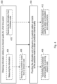
- Figure 4 is a flowchart of a method according to embodiments of the disclosure.
- the method may be performed by a node such as a wireless device (e.g., the wireless device 306 described above) or a network node (e.g., the radio access network node 204 described above, or another network node connected to such a radio access network node 204).
- a node such as a wireless device (e.g., the wireless device 306 described above) or a network node (e.g., the radio access network node 204 described above, or another network node connected to such a radio access network node 204).
- the left-hand side of Figure 4 shows steps which are specific to the former embodiment (where the method is performed by a wireless device); the right-hand side shows steps which are specific to the latter embodiment (where the method is performed by a network node).
- step 400 the node obtains information relating to a channel quality for a first time period, as measured by a wireless node located in an environment (such as the environment 110 described above) comprising one or more machines having mechanical parts which are movable in a periodic pattern.
- a wireless node located in an environment (such as the environment 110 described above) comprising one or more machines having mechanical parts which are movable in a periodic pattern.
- step 400 may comprise the sub-step 404 of performing measurements to obtain the information;
- step 400 may comprise the sub-step 410 of receiving the information from the wireless node.
- the wireless device or node may be configured to report measured values of the channel quality at a lower rate or to stop reporting measured values of the channel quality altogether.
- the wireless device may itself determine that the predicted channel quality matches the measured channel quality adequately and autonomously lower the frequency with which channel quality measurements are performed and/or channel quality reports are transmitted, or stop measuring and/or reporting channel quality altogether.
- the network node may determine that the predicted channel quality matches the measured channel quality adequately and configure the wireless device to stop reporting the measured values of the channel quality, or to lower the frequency with which it does so.
- the node 600 may be connectable to an external power source (e.g., an electricity outlet) via an input circuitry or interface such as an electrical cable, whereby the external power source supplies power to the power circuitry.
- an external power source e.g., an electricity outlet
- the power source may comprise a source of power in the form of a battery or battery pack which is connected to, or integrated in, the power circuitry.
- the battery may provide backup power should the external power source fail.
- Other types of power sources such as photovoltaic devices, may also be used.
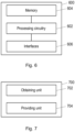
- Figure 6 shows the processing circuitry 602, the memory 604 and the interface(s) 606 coupled together in series, those skilled in the art will appreciate that the components of the node 600 may be coupled together in any suitable manner (e.g. via a bus or other internal connection).
- unit may have conventional meaning in the field of electronics, electrical devices and/or electronic devices and may include, for example, electrical and/or electronic circuitry, devices, units, processors, memories, logic solid state and/or discrete devices, computer programs or instructions for carrying out respective tasks, procedures, computations, outputs, and/or displaying functions, and so on, as such as those that are described herein.
Landscapes
- Engineering & Computer Science (AREA)
- Computer Networks & Wireless Communication (AREA)
- Signal Processing (AREA)
- Physics & Mathematics (AREA)
- Electromagnetism (AREA)
- Artificial Intelligence (AREA)
- Evolutionary Computation (AREA)
- Quality & Reliability (AREA)
- Mobile Radio Communication Systems (AREA)
Claims (17)
- Verfahren zum Schätzen von Kanalqualität in einem drahtlosen Netzwerk, wobei das Verfahren Folgendes umfasst:Erlangen (400) von Informationen in Bezug auf eine Kanalqualität für einen ersten Zeitraum, wie durch einen drahtlosen Knoten (206, 306) gemessen, der sich in einer Umgebung (110) befindet, die eine oder mehrere Maschinen (104, 202, 302) umfasst, die mechanische Teile aufweisen, die in einem periodischen Muster bewegbar sind; undBereitstellen (402) der Informationen als eine Eingabe für ein Vorhersagemodell (212, 312), das unter Verwendung eines Algorithmus für maschinelles Lernen entwickelt wurde, um eine vorhergesagte Kanalqualität in der Umgebung für einen zweiten, nachfolgenden Zeitraum zu erlangen, ferner umfassend Bereitstellen (402) von Informationen in Bezug auf das periodische Muster als eine zweite Eingabe für das Vorhersagemodell, wobei das Vorhersagemodell einen ersten Teil, der anhand von Daten gelernt wurde, die durch eine Vielzahl von drahtlosen Knoten, die sich in der Umgebung befinden, gemessen wurden, und einen zweiten Teil, der anhand von Daten gelernt wurde, die durch den drahtlosen Knoten gemessen wurden, umfasst, wobei der erste Teil eine oder mehrere erste Schichten eines neuronalen Netzwerks umfasst und wobei der zweite Teil eine oder mehrere zweite Schichten des neuronalen Netzwerks umfasst, wobei die zweiten Schichten höher als die ersten Schichten sind.
- Verfahren nach Anspruch 1, wobei die Informationen in Bezug auf das periodische Muster eines oder mehrere der Folgenden umfassen: eine Anzeige einer Frequenz des periodischen Musters; eine Anzeige einer Startzeit jedes Zyklus des periodischen Musters.
- Verfahren nach Anspruch 1 oder 2, das ferner Erlangen der Informationen in Bezug auf das periodische Muster durch Folgendes umfasst: Empfangen (404, 410) einer Anzeige der Informationen in Bezug auf das periodische Muster direkt oder indirekt von der einen oder den mehreren Maschinen oder deren Steuerungen; oder Analysieren der Informationen in Bezug auf die Kanalqualität, um die Informationen in Bezug auf das periodische Muster zu bestimmen.
- Verfahren nach einem der Ansprüche 1 bis 3, wobei die Informationen in Bezug auf das periodische Muster für den ersten Zeitraum eine Periodizität des periodischen Musters umfassen.
- Verfahren nach einem der vorhergehenden Ansprüche, wobei die Informationen in Bezug auf die Kanalqualität für den ersten Zeitraum einen Kanalqualitätsindikatorindex umfassen.
- Verfahren nach einem der vorhergehenden Ansprüche, wobei die Informationen in Bezug auf die Kanalqualität für den ersten Zeitraum eine spektrale Kanalantwort umfassen.
- Verfahren nach einem der vorhergehenden Ansprüche, wobei die vorhergesagte Kanalqualität einen vorhergesagten Kanalqualitätsindikatorindex umfasst.
- Verfahren nach einem der vorhergehenden Ansprüche, wobei die vorhergesagte Kanalqualität eine vorhergesagte spektrale Kanalantwort umfasst.
- Verfahren nach einem der vorhergehenden Ansprüche, wobei das Verfahren durch den drahtlosen Knoten (306) durchgeführt wird.
- Verfahren nach Anspruch 9, das ferner Empfangen (406) des Vorhersagemodells von einem Netzwerkknoten (102, 204, 304) umfasst.
- Verfahren nach Anspruch 9 oder 10, das ferner Übertragen (408) der vorhergesagten Kanalqualität an einen bedienenden Netzwerkknoten (102, 204, 304) für den drahtlosen Knoten umfasst.
- Verfahren nach einem der Ansprüche 1 bis 8, wobei das Verfahren durch einen Netzwerkknoten (102, 204) durchgeführt wird.
- Verfahren nach Anspruch 12, das ferner Verwenden (412) der vorhergesagten Kanalqualität zum Auswählen eines Modulations- und Codierungsschemas für Übertragungen an den drahtlosen Knoten umfasst.
- Verfahren nach einem der vorhergehenden Ansprüche, wobei die Umgebung (110) ein Inneres einer Fabrik umfasst.
- Verfahren nach einem der vorhergehenden Ansprüche, wobei sich der drahtlose Knoten (106, 206, 306) auf einer der Maschinen befindet, die mechanische Teile aufweisen, die in einem periodischen Muster bewegbar sind.
- Nichtflüchtiges maschinenlesbares Medium (604), das Anweisungen speichert, die, wenn sie durch eine Verarbeitungsschaltung (602) eines Computers ausgeführt werden, den Computer veranlassen, das Verfahren nach einem der Ansprüche 1 bis 15 durchzuführen.
- Knoten (600) zum Schätzen von Kanalqualität in einem drahtlosen Netzwerk, wobei der Knoten eine Verarbeitungsschaltung (602) und ein nichtflüchtiges maschinenlesbares Medium (604) umfasst, das Anweisungen speichert, die, wenn sie durch die Verarbeitungsschaltung ausgeführt werden, den Knoten zu Folgendem veranlassen:Erlangen von Informationen in Bezug auf eine Kanalqualität für einen ersten Zeitraum, wie durch einen drahtlosen Knoten (206, 306) gemessen, der sich in einer Umgebung (110) befindet, die eine oder mehrere Maschinen (104, 202, 302) umfasst, die mechanische Teile aufweisen, die in einem periodischen Muster bewegbar sind; undBereitstellen der Informationen als eine Eingabe für ein Vorhersagemodell (212, 312), das unter Verwendung eines Algorithmus für maschinelles Lernen entwickelt wurde, um eine vorhergesagte Kanalqualität in der Umgebung für einen zweiten, nachfolgenden Zeitraum zu erlangen, wobei der Knoten ferner veranlasst wird, Informationen in Bezug auf das periodische Muster als eine zweite Eingabe für das Vorhersagemodell bereitzustellen, wobei das Vorhersagemodell einen ersten Teil, der anhand von Daten gelernt wurde, die durch eine Vielzahl von drahtlosen Knoten, die sich in der Umgebung befinden, gemessen wurden, und einen zweiten Teil, der anhand von Daten gelernt wurde, die durch den drahtlosen Knoten gemessen wurden, umfasst, wobei der erste Teil eine oder mehrere erste Schichten eines neuronalen Netzwerks umfasst und wobei der zweite Teil eine oder mehrere zweite Schichten des neuronalen Netzwerks umfasst, wobei die zweiten Schichten höher als die ersten Schichten sind.
Applications Claiming Priority (1)
| Application Number | Priority Date | Filing Date | Title |
|---|---|---|---|
| PCT/EP2019/078576 WO2021078357A1 (en) | 2019-10-21 | 2019-10-21 | Methods, apparatus and machine-readable media relating to channel quality prediction in a wireless network |
Publications (3)
| Publication Number | Publication Date |
|---|---|
| EP4049474A1 EP4049474A1 (de) | 2022-08-31 |
| EP4049474C0 EP4049474C0 (de) | 2025-07-02 |
| EP4049474B1 true EP4049474B1 (de) | 2025-07-02 |
Family
ID=68318885
Family Applications (1)
| Application Number | Title | Priority Date | Filing Date |
|---|---|---|---|
| EP19791231.4A Active EP4049474B1 (de) | 2019-10-21 | 2019-10-21 | Kanalqualitätsvorhersage in einem drahtlosen netzwerk in einer industriellen umgebung unter verwendung eines prädiktiven modells und eines neuronalen netzwerks |
Country Status (3)
| Country | Link |
|---|---|
| US (1) | US20230155705A1 (de) |
| EP (1) | EP4049474B1 (de) |
| WO (1) | WO2021078357A1 (de) |
Families Citing this family (7)
| Publication number | Priority date | Publication date | Assignee | Title |
|---|---|---|---|---|
| US11877238B2 (en) * | 2021-03-29 | 2024-01-16 | Parsa Wireless Communications Llc | Power saving for multicast broadcast services |
| US12587988B2 (en) | 2021-04-30 | 2026-03-24 | Parsa Wireless Communications Llc | Apparatus and methods for improving time advance alignment process in non-terrestrial wireless network |
| US12256239B2 (en) | 2021-07-12 | 2025-03-18 | Parsa Wireless Communications Llc | Beam tracking in non-terrestrial networking |
| US12309869B2 (en) | 2021-08-06 | 2025-05-20 | Parsa Wireless Communications Llc | Quality of experience in inactive state |
| US12126497B2 (en) | 2021-09-01 | 2024-10-22 | Parsa Wireless Communications Llc | Prediction-based data transmission by internet of things (IoT) devices |
| US20230199565A1 (en) * | 2021-12-20 | 2023-06-22 | Intel Corporation | Methods and devices for management of the radio resources |
| WO2023211345A1 (en) * | 2022-04-28 | 2023-11-02 | Telefonaktiebolaget Lm Ericsson (Publ) | Network configuration identifier signalling for enabling user equipment-based beam predictions |
Family Cites Families (4)
| Publication number | Priority date | Publication date | Assignee | Title |
|---|---|---|---|---|
| US20050227697A1 (en) | 2004-04-12 | 2005-10-13 | Lucent Technologies, Inc. | Method and apparatus for channel prediction in wireless networks |
| US11129077B2 (en) * | 2015-07-10 | 2021-09-21 | Comcast Cable Communications, Llc | Directional router communication and tracking |
| US11665576B2 (en) * | 2018-08-10 | 2023-05-30 | Verizon Patent And Licensing Inc. | Systems and methods for wireless low latency traffic scheduler |
| EP3681180A1 (de) * | 2019-01-09 | 2020-07-15 | Volkswagen Aktiengesellschaft | Verfahren, vorrichtung und computerprogramm zur bestimmung einer vielzahl von verkehrssituationen |
-
2019
- 2019-10-21 US US17/768,304 patent/US20230155705A1/en active Pending
- 2019-10-21 EP EP19791231.4A patent/EP4049474B1/de active Active
- 2019-10-21 WO PCT/EP2019/078576 patent/WO2021078357A1/en not_active Ceased
Also Published As
| Publication number | Publication date |
|---|---|
| WO2021078357A1 (en) | 2021-04-29 |
| EP4049474A1 (de) | 2022-08-31 |
| EP4049474C0 (de) | 2025-07-02 |
| US20230155705A1 (en) | 2023-05-18 |
Similar Documents
| Publication | Publication Date | Title |
|---|---|---|
| EP4049474B1 (de) | Kanalqualitätsvorhersage in einem drahtlosen netzwerk in einer industriellen umgebung unter verwendung eines prädiktiven modells und eines neuronalen netzwerks | |
| US20230262448A1 (en) | Managing a wireless device that is operable to connect to a communication network | |
| US11552688B2 (en) | Channel state information reporting | |
| US20210351885A1 (en) | Method and apparatus for reporting channel state information | |
| CN113992314A (zh) | 链路自适应调整方法、装置、系统和存储介质 | |
| CN118042476A (zh) | 切换或更新ai模型的方法以及通信装置 | |
| CN116711237A (zh) | 信息量化方法、装置、通信设备及存储介质 | |
| US20250373397A1 (en) | Communication method, apparatus, and system | |
| GB2622868A (en) | Devices, methods and apparatuses for channel prediction | |
| WO2023189902A1 (en) | Method, user equipment and access network node | |
| US20260032500A1 (en) | Assisted Communication Systems | |
| US12355531B2 (en) | Channel data transmission method and apparatus, communication device, and storage medium | |
| WO2023227192A1 (en) | Apparatuses and methods for generating training data for radio-aware digital twin | |
| WO2024255041A1 (en) | Communication method and communication apparatus | |
| WO2024255036A1 (en) | Communication method and communication apparatus | |
| EP4597872A1 (de) | Strahlvorhersage | |
| WO2024255044A1 (en) | Communication method and communication apparatus | |
| WO2024255039A1 (en) | Communication method and communication apparatus | |
| WO2024255037A1 (en) | Communication method and communication apparatus | |
| EP4604598A1 (de) | Verfahren, vorrichtung und computerprogramme zur überwachung von modellen in einem kommunikationsnetz | |
| WO2024235250A1 (en) | Method and apparatus of monitoring event detection for artificial intelligence/machine learning models in wireless communications | |
| WO2024255034A1 (en) | Communication method and communication apparatus | |
| CN119719703A (zh) | 用于测试基于模型的预测准确度的机制 | |
| CN120935641A (zh) | 一种预测方法和通信装置 | |
| KR20250124213A (ko) | 통신 방법 및 통신 장치 |
Legal Events
| Date | Code | Title | Description |
|---|---|---|---|
| STAA | Information on the status of an ep patent application or granted ep patent |
Free format text: STATUS: UNKNOWN |
|
| STAA | Information on the status of an ep patent application or granted ep patent |
Free format text: STATUS: THE INTERNATIONAL PUBLICATION HAS BEEN MADE |
|
| PUAI | Public reference made under article 153(3) epc to a published international application that has entered the european phase |
Free format text: ORIGINAL CODE: 0009012 |
|
| STAA | Information on the status of an ep patent application or granted ep patent |
Free format text: STATUS: REQUEST FOR EXAMINATION WAS MADE |
|
| 17P | Request for examination filed |
Effective date: 20220331 |
|
| AK | Designated contracting states |
Kind code of ref document: A1 Designated state(s): AL AT BE BG CH CY CZ DE DK EE ES FI FR GB GR HR HU IE IS IT LI LT LU LV MC MK MT NL NO PL PT RO RS SE SI SK SM TR |
|
| DAV | Request for validation of the european patent (deleted) | ||
| DAX | Request for extension of the european patent (deleted) | ||
| REG | Reference to a national code |
Ref country code: DE Ref legal event code: R079 Free format text: PREVIOUS MAIN CLASS: H04W0016220000 Ipc: H04W0016200000 Ref country code: DE Ref legal event code: R079 Ref document number: 602019071979 Country of ref document: DE Free format text: PREVIOUS MAIN CLASS: H04W0016220000 Ipc: H04W0016200000 |
|
| GRAP | Despatch of communication of intention to grant a patent |
Free format text: ORIGINAL CODE: EPIDOSNIGR1 |
|
| STAA | Information on the status of an ep patent application or granted ep patent |
Free format text: STATUS: GRANT OF PATENT IS INTENDED |
|
| RIC1 | Information provided on ipc code assigned before grant |
Ipc: H04W 24/04 20090101ALI20250113BHEP Ipc: H04W 24/02 20090101ALI20250113BHEP Ipc: H04W 16/22 20090101ALI20250113BHEP Ipc: H04W 16/20 20090101AFI20250113BHEP |
|
| INTG | Intention to grant announced |
Effective date: 20250207 |
|
| GRAS | Grant fee paid |
Free format text: ORIGINAL CODE: EPIDOSNIGR3 |
|
| GRAA | (expected) grant |
Free format text: ORIGINAL CODE: 0009210 |
|
| STAA | Information on the status of an ep patent application or granted ep patent |
Free format text: STATUS: THE PATENT HAS BEEN GRANTED |
|
| AK | Designated contracting states |
Kind code of ref document: B1 Designated state(s): AL AT BE BG CH CY CZ DE DK EE ES FI FR GB GR HR HU IE IS IT LI LT LU LV MC MK MT NL NO PL PT RO RS SE SI SK SM TR |
|
| REG | Reference to a national code |
Ref country code: GB Ref legal event code: FG4D |
|
| REG | Reference to a national code |
Ref country code: CH Ref legal event code: EP |
|
| REG | Reference to a national code |
Ref country code: DE Ref legal event code: R096 Ref document number: 602019071979 Country of ref document: DE |
|
| REG | Reference to a national code |
Ref country code: IE Ref legal event code: FG4D |
|
| U01 | Request for unitary effect filed |
Effective date: 20250714 |
|
| U07 | Unitary effect registered |
Designated state(s): AT BE BG DE DK EE FI FR IT LT LU LV MT NL PT RO SE SI Effective date: 20250718 |
|
| U20 | Renewal fee for the european patent with unitary effect paid |
Year of fee payment: 7 Effective date: 20251027 |
|
| PG25 | Lapsed in a contracting state [announced via postgrant information from national office to epo] |
Ref country code: IS Free format text: LAPSE BECAUSE OF FAILURE TO SUBMIT A TRANSLATION OF THE DESCRIPTION OR TO PAY THE FEE WITHIN THE PRESCRIBED TIME-LIMIT Effective date: 20251102 |
|
| PGFP | Annual fee paid to national office [announced via postgrant information from national office to epo] |
Ref country code: GB Payment date: 20251027 Year of fee payment: 7 |
|
| PG25 | Lapsed in a contracting state [announced via postgrant information from national office to epo] |
Ref country code: NO Free format text: LAPSE BECAUSE OF FAILURE TO SUBMIT A TRANSLATION OF THE DESCRIPTION OR TO PAY THE FEE WITHIN THE PRESCRIBED TIME-LIMIT Effective date: 20251002 |
|
| PG25 | Lapsed in a contracting state [announced via postgrant information from national office to epo] |
Ref country code: HR Free format text: LAPSE BECAUSE OF FAILURE TO SUBMIT A TRANSLATION OF THE DESCRIPTION OR TO PAY THE FEE WITHIN THE PRESCRIBED TIME-LIMIT Effective date: 20250702 |
|
| PG25 | Lapsed in a contracting state [announced via postgrant information from national office to epo] |
Ref country code: GR Free format text: LAPSE BECAUSE OF FAILURE TO SUBMIT A TRANSLATION OF THE DESCRIPTION OR TO PAY THE FEE WITHIN THE PRESCRIBED TIME-LIMIT Effective date: 20251003 |
|
| PG25 | Lapsed in a contracting state [announced via postgrant information from national office to epo] |
Ref country code: CZ Free format text: LAPSE BECAUSE OF FAILURE TO SUBMIT A TRANSLATION OF THE DESCRIPTION OR TO PAY THE FEE WITHIN THE PRESCRIBED TIME-LIMIT Effective date: 20250702 |
|
| PG25 | Lapsed in a contracting state [announced via postgrant information from national office to epo] |
Ref country code: PL Free format text: LAPSE BECAUSE OF FAILURE TO SUBMIT A TRANSLATION OF THE DESCRIPTION OR TO PAY THE FEE WITHIN THE PRESCRIBED TIME-LIMIT Effective date: 20250702 |
|
| PG25 | Lapsed in a contracting state [announced via postgrant information from national office to epo] |
Ref country code: RS Free format text: LAPSE BECAUSE OF FAILURE TO SUBMIT A TRANSLATION OF THE DESCRIPTION OR TO PAY THE FEE WITHIN THE PRESCRIBED TIME-LIMIT Effective date: 20251002 |
|
| PG25 | Lapsed in a contracting state [announced via postgrant information from national office to epo] |
Ref country code: ES Free format text: LAPSE BECAUSE OF FAILURE TO SUBMIT A TRANSLATION OF THE DESCRIPTION OR TO PAY THE FEE WITHIN THE PRESCRIBED TIME-LIMIT Effective date: 20250702 |
|
| PG25 | Lapsed in a contracting state [announced via postgrant information from national office to epo] |
Ref country code: SM Free format text: LAPSE BECAUSE OF FAILURE TO SUBMIT A TRANSLATION OF THE DESCRIPTION OR TO PAY THE FEE WITHIN THE PRESCRIBED TIME-LIMIT Effective date: 20250702 |
|
| PG25 | Lapsed in a contracting state [announced via postgrant information from national office to epo] |
Ref country code: SK Free format text: LAPSE BECAUSE OF FAILURE TO SUBMIT A TRANSLATION OF THE DESCRIPTION OR TO PAY THE FEE WITHIN THE PRESCRIBED TIME-LIMIT Effective date: 20250702 |