EP4048897B1 - Turbomachine provided with an electromagnetic pump with axial magnetic flux - Google Patents
Turbomachine provided with an electromagnetic pump with axial magnetic flux Download PDFInfo
- Publication number
- EP4048897B1 EP4048897B1 EP20803218.5A EP20803218A EP4048897B1 EP 4048897 B1 EP4048897 B1 EP 4048897B1 EP 20803218 A EP20803218 A EP 20803218A EP 4048897 B1 EP4048897 B1 EP 4048897B1
- Authority
- EP
- European Patent Office
- Prior art keywords
- coils
- pump
- magnets
- electromagnetic pump
- turbomachine
- Prior art date
- Legal status (The legal status is an assumption and is not a legal conclusion. Google has not performed a legal analysis and makes no representation as to the accuracy of the status listed.)
- Active
Links
- 230000004907 flux Effects 0.000 title 1
- 239000012530 fluid Substances 0.000 claims description 5
- 230000015556 catabolic process Effects 0.000 description 5
- 230000005672 electromagnetic field Effects 0.000 description 5
- 239000000446 fuel Substances 0.000 description 5
- 230000010354 integration Effects 0.000 description 5
- 239000007788 liquid Substances 0.000 description 4
- 230000001172 regenerating effect Effects 0.000 description 4
- 239000007787 solid Substances 0.000 description 4
- 239000000470 constituent Substances 0.000 description 3
- 208000031968 Cadaver Diseases 0.000 description 1
- 239000002775 capsule Substances 0.000 description 1
- 230000001419 dependent effect Effects 0.000 description 1
- 239000002828 fuel tank Substances 0.000 description 1
- 238000002513 implantation Methods 0.000 description 1
- 239000000314 lubricant Substances 0.000 description 1
- 238000005461 lubrication Methods 0.000 description 1
- 125000006850 spacer group Chemical group 0.000 description 1
- 238000004804 winding Methods 0.000 description 1
Images


Classifications
-
- F—MECHANICAL ENGINEERING; LIGHTING; HEATING; WEAPONS; BLASTING
- F04—POSITIVE - DISPLACEMENT MACHINES FOR LIQUIDS; PUMPS FOR LIQUIDS OR ELASTIC FLUIDS
- F04C—ROTARY-PISTON, OR OSCILLATING-PISTON, POSITIVE-DISPLACEMENT MACHINES FOR LIQUIDS; ROTARY-PISTON, OR OSCILLATING-PISTON, POSITIVE-DISPLACEMENT PUMPS
- F04C2/00—Rotary-piston machines or pumps
- F04C2/08—Rotary-piston machines or pumps of intermeshing-engagement type, i.e. with engagement of co-operating members similar to that of toothed gearing
- F04C2/10—Rotary-piston machines or pumps of intermeshing-engagement type, i.e. with engagement of co-operating members similar to that of toothed gearing of internal-axis type with the outer member having more teeth or tooth-equivalents, e.g. rollers, than the inner member
-
- F—MECHANICAL ENGINEERING; LIGHTING; HEATING; WEAPONS; BLASTING
- F04—POSITIVE - DISPLACEMENT MACHINES FOR LIQUIDS; PUMPS FOR LIQUIDS OR ELASTIC FLUIDS
- F04C—ROTARY-PISTON, OR OSCILLATING-PISTON, POSITIVE-DISPLACEMENT MACHINES FOR LIQUIDS; ROTARY-PISTON, OR OSCILLATING-PISTON, POSITIVE-DISPLACEMENT PUMPS
- F04C15/00—Component parts, details or accessories of machines, pumps or pumping installations, not provided for in groups F04C2/00 - F04C14/00
- F04C15/0057—Driving elements, brakes, couplings, transmission specially adapted for machines or pumps
- F04C15/008—Prime movers
-
- F—MECHANICAL ENGINEERING; LIGHTING; HEATING; WEAPONS; BLASTING
- F02—COMBUSTION ENGINES; HOT-GAS OR COMBUSTION-PRODUCT ENGINE PLANTS
- F02C—GAS-TURBINE PLANTS; AIR INTAKES FOR JET-PROPULSION PLANTS; CONTROLLING FUEL SUPPLY IN AIR-BREATHING JET-PROPULSION PLANTS
- F02C7/00—Features, components parts, details or accessories, not provided for in, or of interest apart form groups F02C1/00 - F02C6/00; Air intakes for jet-propulsion plants
- F02C7/32—Arrangement, mounting, or driving, of auxiliaries
-
- F—MECHANICAL ENGINEERING; LIGHTING; HEATING; WEAPONS; BLASTING
- F04—POSITIVE - DISPLACEMENT MACHINES FOR LIQUIDS; PUMPS FOR LIQUIDS OR ELASTIC FLUIDS
- F04C—ROTARY-PISTON, OR OSCILLATING-PISTON, POSITIVE-DISPLACEMENT MACHINES FOR LIQUIDS; ROTARY-PISTON, OR OSCILLATING-PISTON, POSITIVE-DISPLACEMENT PUMPS
- F04C15/00—Component parts, details or accessories of machines, pumps or pumping installations, not provided for in groups F04C2/00 - F04C14/00
- F04C15/0057—Driving elements, brakes, couplings, transmission specially adapted for machines or pumps
- F04C15/0061—Means for transmitting movement from the prime mover to driven parts of the pump, e.g. clutches, couplings, transmissions
- F04C15/0069—Magnetic couplings
-
- F—MECHANICAL ENGINEERING; LIGHTING; HEATING; WEAPONS; BLASTING
- F04—POSITIVE - DISPLACEMENT MACHINES FOR LIQUIDS; PUMPS FOR LIQUIDS OR ELASTIC FLUIDS
- F04C—ROTARY-PISTON, OR OSCILLATING-PISTON, POSITIVE-DISPLACEMENT MACHINES FOR LIQUIDS; ROTARY-PISTON, OR OSCILLATING-PISTON, POSITIVE-DISPLACEMENT PUMPS
- F04C2/00—Rotary-piston machines or pumps
- F04C2/08—Rotary-piston machines or pumps of intermeshing-engagement type, i.e. with engagement of co-operating members similar to that of toothed gearing
- F04C2/10—Rotary-piston machines or pumps of intermeshing-engagement type, i.e. with engagement of co-operating members similar to that of toothed gearing of internal-axis type with the outer member having more teeth or tooth-equivalents, e.g. rollers, than the inner member
- F04C2/102—Rotary-piston machines or pumps of intermeshing-engagement type, i.e. with engagement of co-operating members similar to that of toothed gearing of internal-axis type with the outer member having more teeth or tooth-equivalents, e.g. rollers, than the inner member the two members rotating simultaneously around their respective axes
-
- F—MECHANICAL ENGINEERING; LIGHTING; HEATING; WEAPONS; BLASTING
- F04—POSITIVE - DISPLACEMENT MACHINES FOR LIQUIDS; PUMPS FOR LIQUIDS OR ELASTIC FLUIDS
- F04C—ROTARY-PISTON, OR OSCILLATING-PISTON, POSITIVE-DISPLACEMENT MACHINES FOR LIQUIDS; ROTARY-PISTON, OR OSCILLATING-PISTON, POSITIVE-DISPLACEMENT PUMPS
- F04C7/00—Rotary-piston machines or pumps with fluid ring or the like
-
- F—MECHANICAL ENGINEERING; LIGHTING; HEATING; WEAPONS; BLASTING
- F04—POSITIVE - DISPLACEMENT MACHINES FOR LIQUIDS; PUMPS FOR LIQUIDS OR ELASTIC FLUIDS
- F04C—ROTARY-PISTON, OR OSCILLATING-PISTON, POSITIVE-DISPLACEMENT MACHINES FOR LIQUIDS; ROTARY-PISTON, OR OSCILLATING-PISTON, POSITIVE-DISPLACEMENT PUMPS
- F04C2240/00—Components
- F04C2240/40—Electric motor
-
- Y—GENERAL TAGGING OF NEW TECHNOLOGICAL DEVELOPMENTS; GENERAL TAGGING OF CROSS-SECTIONAL TECHNOLOGIES SPANNING OVER SEVERAL SECTIONS OF THE IPC; TECHNICAL SUBJECTS COVERED BY FORMER USPC CROSS-REFERENCE ART COLLECTIONS [XRACs] AND DIGESTS
- Y02—TECHNOLOGIES OR APPLICATIONS FOR MITIGATION OR ADAPTATION AGAINST CLIMATE CHANGE
- Y02T—CLIMATE CHANGE MITIGATION TECHNOLOGIES RELATED TO TRANSPORTATION
- Y02T50/00—Aeronautics or air transport
- Y02T50/60—Efficient propulsion technologies, e.g. for aircraft
Definitions
- the present invention relates to the field of turbomachines of the type comprising a rotating body comprising a motor shaft delivering mechanical power.
- the invention applies to all types of turbomachines, in particular those used in aircraft such as turbojets, turboprops, and turbomachines with unducted fans, also known by the Anglo-Saxon term "Open Rotor”.
- a conventional turbomachine comprises one or more rotating bodies in a known manner.
- Each rotating body includes a compressor, a turbine, and a motor shaft connecting the turbine to the compressor to drive the compressor to rotate.
- Part of the power generated by the turbomachine is used to drive various accessories (or auxiliary machines), necessary for the operation of the turbojet or the aircraft, such as for example a lubrication pump or a fuel pump.
- the turbomachine generally includes an accessory gear box (Accessory Gear Box) connecting the motor shaft to the pumps.
- an accessory gear box Accessory Gear Box
- the accessory gearbox transmits the rotational movement to the various accessories.
- the mechanical energy produced by the motor shaft is transmitted to the pumps through the accessory gearbox.
- the document US 2010/0003148 A1 discloses a turbomachine comprising a fuel pump driven by an electric motor and as a backup, by an air turbine.
- the invention aims in particular to provide a turbomachine which does not have the aforementioned drawbacks.
- a turbomachine comprising a rotating body comprising a motor shaft delivering mechanical power, characterized in that it comprises at least one electromagnetic pump mechanically decoupled from the motor shaft, each electromagnetic pump comprising at least one stator delimiting an annular internal volume in which is present a rotor capable of driving a fluid, a plurality of magnets distributed annularly on the rotor and at least a plurality of coils distributed annularly inside the stator, the coils of the plurality of coils facing the magnets in an axial direction.
- the turbomachine according to the invention is thus equipped with one or more pumps which are mechanically decoupled from the motor shaft and which are controlled independently of the engine speed. It is thus possible to have greater freedom in the choice of the rotation speed of the pump and in the possibilities of installing the pump(s) in the turbomachine.
- the radial bulk of the pump is greatly optimized. This results in a very compact pump.
- the rotor comprises a wheel provided with a plurality of blades, the magnets of the plurality of magnets being held at the level of the external periphery of the wheel.
- each electromagnetic pump comprises first and second pluralities of coils present respectively on one side and on the other side of the wheel, the coils of the first and second pluralities of coils being facing the magnets in the axial direction.
- Two pluralities of coils ensure redundancy in the event of breakdown or failure of a plurality of coils. The redundancy of the plurality of coils can also be used to double the strength of the electromagnetic fields to which the permanent magnets are subjected.
- the rotor comprises an internal pinion cooperating with an external crown with internal teeth, the magnets of the plurality of magnets being held at the level of the external periphery of the external crown.
- each electromagnetic pump comprises first and second pluralities of coils present respectively on one side and on the other side of the outer ring, the coils of the first and second pluralities of coils being opposite the magnets in the axial direction.
- the use of two pluralities of coils makes it possible to ensure redundancy in the event of breakdown or failure of a plurality of coils and/or to double the power of the electromagnetic fields to which the permanent magnets are subjected.
- the rotor comprises an internal pinion cooperating with an external ring gear with internal teeth, the magnets of the plurality of magnets being held on the internal pinion.
- each electromagnetic pump comprises first and second pluralities of coils present respectively on one side and on the other side of the pinion, the coils of the first and second pluralities of coils being in with respect to the magnets in the axial direction.
- the use of two pluralities of coils makes it possible to ensure redundancy in the event of breakdown or failure of a plurality of coil and/or to double the power of the electromagnetic fields to which permanent magnets are subjected.
- the magnets of the plurality of magnets are arranged in an annular manner according to a Halbach structure.
- This particular arrangement makes it possible to increase the magnetic field on the external side of the rotor while the magnetic field on the internal side of the rotor is substantially canceled. This reduces the loss of the magnetic field, which improves the control of the rotor by the coils.
- the invention also relates to an aircraft comprising at least one turboprop or a turbojet comprising a turbomachine according to the invention.
- the invention generally applies to any turbomachine equipped with at least one pump controlled independently of the engine speed of the turbomachine. It applies in particular, but not exclusively, to pumps of the liquid ring, side channel or regenerative and gerotor type.
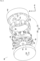
- the electromagnetic pump 100 is a liquid ring type pump comprising a fixed pump body or stator 110 consisting of a casing 111 and a flange 112.
- the casing 111 comprises a solid cylindrical central part 1110 provided with a suction/discharge port 1111 and a circular outer wall 1112 extending concentrically around the central part 1110, annular housings 1113 being delimited between the central part 1110 and the outer wall 1112.
- the flange 112 comprises a discharge/suction port 1120.
- the electromagnetic pump 100 also comprises a bladed wheel or rotor 120 comprising a wheel 121 provided with a plurality of blades 122 extending from the wheel in a radial direction D R , a ring 123 being present at the external periphery of the wheel.
- the ring 123 is fixed on the radially external ends of the blades 122.
- the blade wheel 120 comprises a rotation shaft 124 intended to be supported by bearings 1114 and 1124 present respectively on the casing 111 and the flange 112.
- the shaft is placed eccentrically on the impeller 120, for example by means of a spacer (not shown on the figures 1 And 2 ) so as to create inter-blade (or inter-blade) volume variations which make it possible to suck in the pumped fluid, for example through port 1111, then evacuate it under pressure, for example through port 1120.
- the pump 100 can also be a side channel pump, also called a regenerative pump. In this case and in known manner, a side channel 1125 (dotted on the figure 1 ) present here on the flange 112 extends between ports 1111 and 1120.
- the electromagnetic pump 100 further comprises a plurality of permanent magnets 130 distributed in an annular manner on the impeller or rotor 120 and a plurality of coils 140 distributed in an annular manner inside the fixed pump body or stator 110. More precisely, in the example described here, the permanent magnets 130 are held in housings 1230 present in the ring 123 while the coils 140 are held in the annular housing 1113 present in the casing 111.
- the coils 140 are located opposite the permanent magnets 130 in an axial direction D A.
- the control of the electromagnetic pump 100 is carried out by controlling the current circulating in the coils.
- part of the pump drive means is integrated directly within the moving elements, which makes it possible to obtain a high level of integration of the means of drive and therefore reduced bulk for the pump.
- THE figures 3 And 4 illustrate another embodiment of an electromagnetic pump 200 which differs from the electromagnetic pump 100 described in relation to the figures 1 And 2 in that it includes a double coil. More precisely, as for the pump 100, the pump 200 comprises a bladed wheel or rotor 220 comprising a wheel 221 provided with a plurality of blades 222 extending from the wheel in a radial direction D R , a fixed ring 223 on the radially external ends of the blades 222.
- the electromagnetic pump 200 also comprising a fixed pump body or stator 210 consisting of a first casing 211 and a second casing 212.
- the casings 211 and 212 each respectively comprise a solid cylindrical central part 2110, 2120 provided with a port suction/discharge 2111, 2121 and a circular external wall 2112, 2122 extending concentrically around the central part 2110, 2120.
- First annular housings 2113 are delimited in the first casing 211 between the central part 2110 and the external wall 2112.
- Second annular housings 2123 are delimited in the second casing 212 between the central part 2120 and the external wall 2122.
- the electromagnetic pump 200 further comprises a plurality of permanent magnets 230 held in an annular manner in housings 2230 present in the ring 223 and first and second pluralities of coils 240 and 250.
- the first plurality of coils 240 is distributed in an annular manner in the first annular housings 2113 while the second plurality of coils 250 is distributed annularly in the second annular housings 2123.
- the rotation shaft 224 of the impeller 220 is supported by bearings 2214 and 2224 present respectively on the first and second casings 211 and 212 while the first and second pluralities of coils 240 and 250 are present respectively on one side and on the other side of the wheel 220 and opposite the magnets in an axial direction D A.
- the electromagnetic pump 200 comprises two pluralities of coils which make it possible to ensure redundancy in the event of breakdown or failure of a plurality of coils, each plurality of coil having its own connections to the piloting system.
- the redundancy of the plurality of coils can also be used to double the strength of the electromagnetic fields to which the permanent magnets are subjected. It should also be noted that, always in the interest of optimizing the size of the pump, only the plurality of coils is redundant, and this as close as possible to the permanent magnets.
- the pump 200 can also be a side channel pump, also called a regenerative pump as explained previously in relation to the pump 100.
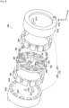
- the pump 300 is a gerotor type pump comprising a fixed pump body or stator 310 consisting of a casing 311 and a flange 312.
- the casing 311 comprises a solid cylindrical central part 3110 and a wall circular external 3112 extending concentrically around the central part 3110, annular housings 3113 being delimited between the central part 3110 and the external wall 3112.
- the flange 312 comprises a suction port 3120 and a discharge port 3121.
- the electromagnetic pump 300 also comprises a rotor 320 comprising an inner pinion 321 and an outer ring gear 322 present around the inner pinion 321 in a radial direction D R.
- the inner pinion comprises external teeth consisting here of six teeth 3210 while the outer crown 322 comprises internal teeth consisting here of 7 teeth 3220.
- the inner pinion 321 comprises a rotation shaft 324 intended to be supported by bearings 3114 and 3124 present respectively on the casing 311 and the flange 312.
- a fluid is sucked in from port 3120 and delivered via port 3121 by capsules created between the teeth 3210 and 3220 respectively of the internal pinion 321 and the outer ring 322 during the rotation of these two elements.
- the electromagnetic pump 300 further comprises a plurality of permanent magnets 330 distributed in an annular manner on the external periphery of the outer ring 322 and a plurality of coils 340 distributed in an annular manner inside the fixed pump body or stator 310. More precisely, in the example described here, the permanent magnets 330 are held in housings 3221 present in the outer ring 322 while the coils 340 are held in the annular housings 3113 present in the casing 311.
- the coils 340 are located opposite the permanent magnets 330 in an axial direction D A.
- the control of the electromagnetic pump 300 is carried out by controlling the current circulating in the coils.
- part of the pump drive means is integrated directly within the moving elements, which makes it possible to obtain a high level of integration of the drive means. and therefore reduced bulk for the pump.
- THE figures 7 And 8 illustrate another embodiment of an electromagnetic pump 400 which differs from the electromagnetic pump 300 described in relation to the figures 5 And 6 in that it includes a double coil. More precisely, as for the pump 300, the pump 400 comprises a rotor 420 comprising an internal pinion 421 having external teeth consisting here of six teeth 4210 and an external crown 422 having internal teeth consisting here of 7 teeth 4220, the external crown 422 being present around the internal pinion 421 in a radial direction D R.
- the electromagnetic pump 400 also comprises a fixed pump body or stator 410 consisting of a first casing 411 and a second casing 412.
- the casings 411 and 412 each respectively comprise a solid cylindrical central part 4110, 4120 and a circular outer wall 4112, 4122 extending concentrically around the central part 4110, 4120, the central part 4120 of the casing 412 comprising a suction port 4121 and a discharge port 4124.
- First annular housings 4113 are delimited in the first casing 411 between the central part 4110 and the external wall 4112.
- a second annular housing 4123 is delimited in the second casing 412 between the central part 4120 and the external wall 4122.
- the electromagnetic pump 400 further comprises a plurality of permanent magnets 430 held in an annular manner in housings 4221 present in the outer ring 422 and first and second pluralities of coils 440 and 450.
- the first plurality of coils 440 is distributed annularly in the first annular housings 4113 while the second plurality of coils 450 is distributed annularly in the second annular housings 4123.
- the rotation shaft 424 of the internal pinion 421 is supported by bearings 4114 and 4124 present respectively on the first and second casings 411 and 412 while the first and second pluralities of coils 440 and 450 are present respectively on one side and on the other side of the outer ring 422 and opposite the magnets in an axial direction D A.
- the electromagnetic pump 400 comprises two pluralities of coils which make it possible to ensure redundancy in the event of breakdown or failure of a plurality of coils, each plurality of coils having their own connections to the control system.
- the redundancy of the plurality of coils can also be used to double the strength of the electromagnetic fields to which the permanent magnets are subjected. It should also be noted that, always in the interest of optimizing the size of the pump, only the plurality of coils is redundant, and this as close as possible to the permanent magnets.
- the gerotor type pump 500 comprises a fixed pump body or stator 510 consisting of a casing 511 and a flange 512.
- the casing 511 comprises annular housings 5113.
- the flange 512 comprises a 5120 suction port and a 5121 discharge port.
- the electromagnetic pump 500 also comprises a rotor 520 comprising an inner pinion 521 and an outer ring gear 522 present around the inner pinion 521 in a radial direction D R.
- the inner gear includes a external teeth consisting here of six teeth 5210 while the external crown 522 comprises internal teeth consisting here of 7 teeth 5220.
- the internal pinion 521 comprises a rotation shaft 524 intended to be supported by bearings 5114 and 5124 present respectively on the casing 511 and the flask 512.
- the electromagnetic pump 500 further comprises a plurality of permanent magnets 530 held in an annular manner in the internal pinion 521 around the rotation shaft 524 and a plurality of coils 540 held in the annular housings 5113 present in the casing 511.
- the coils 540 are located opposite the permanent magnets 530 in an axial direction D A.
- the control of the electromagnetic pump 500 is carried out by controlling the current circulating in the coils.
- part of the pump drive means is integrated directly within the moving elements, which makes it possible to obtain a high level of integration of the drive means. and therefore reduced bulk for the pump.
- the electromagnetic pump 500 can be equipped with a double winding, namely comprising first and second pluralities of coils present respectively on one side and on the other side of the internal pinion, the coils first and second pluralities of coils facing the magnets in the axial direction.
- the permanent magnets present on the external ring of the impeller for the embodiments described above in relation to the figures 1 to 4 , or on the outer crown for the embodiments described above in relation to the figures 5 to 8 , or on the internal pinion for the embodiment described above in relation to the figures 9 And 10 can be arranged following a Halbach structure.
- FIG. 11 illustrates an example of arrangement of permanent magnets following a Halbach structure.
- permanent magnets 10 are distributed in an annular manner as in the rotors described previously by reversing the polarity of the magnets in the radial direction and in the circumferential direction as represented by the arrows indicated on the Figure 11 .
- This particular arrangement makes it possible to increase the magnetic field 20 on the external side of the rotor while the magnetic field on the internal side of the rotor is substantially canceled. This reduces the loss of the magnetic field, which improves the control of the rotor by the coils.
- the electromagnetic pump according to the invention can be used in particular to supply fuel or lubricant to the turbomachine.
- FIG. 12 illustrates an example of a turbomachine which comprises a fuel supply line composed here of a fuel tank 10, a low pressure pump 11, a filter 12, a high pressure pump 13, a device metering device 14 and an oil/fuel heat exchanger 15.
- the turbomachine also includes an accessories box 17 (“gear box”) to which is connected a motor shaft 18 intended to deliver mechanical power in the turbomachine.
- the low pressure pump 11 and the high pressure pump 13 consist of an electromagnetic pump, for example of the liquid ring type or of the lateral or regenerative channel type.
- the low pressure pump 11 and the high pressure pump 13 are mechanically decoupled from the motor shaft 18 and are each controlled independently, for example the digital computer 16 integrated into the turbomachine control device.
- the low and/or high pressure supply pumps can also be replaced partly or entirely by electromagnetic pumps controlled independently of the engine speed.
- gerotor type pumps are preferably but not exclusively used.
Description
La présente invention concerne le domaine des turbomachines du type comprenant un corps rotatif comprenant un arbre moteur délivrant une puissance mécanique. L'invention s'applique à tout type de turbomachines, en particulier celles utilisées dans les aéronefs comme les turboréacteurs, turbopropulseurs, et turbomachines à soufflantes non carénées, aussi connues sous le vocable anglo-saxon de « Open Rotor ».The present invention relates to the field of turbomachines of the type comprising a rotating body comprising a motor shaft delivering mechanical power. The invention applies to all types of turbomachines, in particular those used in aircraft such as turbojets, turboprops, and turbomachines with unducted fans, also known by the Anglo-Saxon term "Open Rotor".
Une turbomachine conventionnelle comporte de manière connue un ou plusieurs corps rotatifs. Chaque corps rotatif comprend un compresseur, une turbine et un arbre moteur reliant la turbine au compresseur pour entraîner le compresseur en rotation. Une partie de la puissance générée par la turbomachine est utilisée pour entraîner différents accessoires (ou machines auxiliaires), nécessaires au fonctionnement du turboréacteur ou de l'aéronef, tels que par exemple une pompe de lubrification ou une pompe à carburant.A conventional turbomachine comprises one or more rotating bodies in a known manner. Each rotating body includes a compressor, a turbine, and a motor shaft connecting the turbine to the compressor to drive the compressor to rotate. Part of the power generated by the turbomachine is used to drive various accessories (or auxiliary machines), necessary for the operation of the turbojet or the aircraft, such as for example a lubrication pump or a fuel pump.
A cet effet, la turbomachine comprend généralement une boîte d'engrenage d'accessoire (Accessory Gear Box) reliant l'arbre moteur aux pompes. Lorsque l'arbre moteur est entraîné en rotation, la boîte d'engrenage d'accessoires transmet le mouvement de rotation aux différents accessoires. En d'autres termes, l'énergie mécanique produite par l'arbre moteur est transmise aux pompes par la boîte d'engrenage d'accessoires.For this purpose, the turbomachine generally includes an accessory gear box (Accessory Gear Box) connecting the motor shaft to the pumps. When the motor shaft is rotated, the accessory gearbox transmits the rotational movement to the various accessories. In other words, the mechanical energy produced by the motor shaft is transmitted to the pumps through the accessory gearbox.
Cette solution technique présente toutefois les inconvénients suivants :
- une partie de la puissance mécanique délivrée par le corps rotatif est prélevée pour entraîner la ou les pompes,
- la vitesse de rotation de la ou des pompes est dépendante de la vitesse de rotation de l'arbre moteur, la ou les pompes ne pouvant alors pas être pilotées selon un régime moteur indépendant,
- la liaison mécanique entre l'arbre moteur et la ou les pompes nécessite des étanchéités dynamiques qui sont difficiles à réaliser,
- la liaison mécanique entre l'arbre moteur et la ou les pompes requière de placer la ou les pompes au voisinage de la boîte d'engrenage d'accessoires, ce qui limite grandement les possibilités d'implantation de la ou des pompes dans une turbomachine.
- part of the mechanical power delivered by the rotating body is taken to drive the pump(s),
- the rotation speed of the pump(s) is dependent on the rotation speed of the motor shaft, the pump(s) cannot then be controlled according to an independent engine speed,
- the mechanical connection between the motor shaft and the pump(s) requires dynamic seals which are difficult to achieve,
- the mechanical connection between the motor shaft and the pump(s) requires placing the pump(s) in the vicinity of the accessory gearbox, which greatly limits the possibilities of installing the pump(s) in a turbomachine.
Le document
L'invention a notamment pour but de fournir une turbomachine ne présentant pas les inconvénients précités.The invention aims in particular to provide a turbomachine which does not have the aforementioned drawbacks.
Ce but est atteint grâce à une turbomachine comprenant un corps rotatif comprenant un arbre moteur délivrant une puissance mécanique, caractérisée en ce qu'elle comprend au moins une pompe électromagnétique découplée mécaniquement de l'arbre moteur, chaque pompe électromagnétique comprenant au moins un stator délimitant un volume interne annulaire dans lequel est présent un rotor apte à entraîner un fluide, une pluralité d'aimants répartis de manière annulaire sur le rotor et au moins une pluralité de bobines réparties de manière annulaire à l'intérieur du stator, les bobines de la pluralité de bobines étant en vis-à-vis des aimants suivant une direction axiale.This goal is achieved thanks to a turbomachine comprising a rotating body comprising a motor shaft delivering mechanical power, characterized in that it comprises at least one electromagnetic pump mechanically decoupled from the motor shaft, each electromagnetic pump comprising at least one stator delimiting an annular internal volume in which is present a rotor capable of driving a fluid, a plurality of magnets distributed annularly on the rotor and at least a plurality of coils distributed annularly inside the stator, the coils of the plurality of coils facing the magnets in an axial direction.
La turbomachine selon l'invention est ainsi équipée d'une ou plusieurs pompes qui sont découplées mécaniquement de l'arbre moteur et qui sont pilotées indépendamment du régime moteur. Il est ainsi possible d'avoir une plus grande liberté sur le choix de la vitesse de rotation de la pompe et sur les possibilités d'implantation de la ou les pompes dans la turbomachine.The turbomachine according to the invention is thus equipped with one or more pumps which are mechanically decoupled from the motor shaft and which are controlled independently of the engine speed. It is thus possible to have greater freedom in the choice of the rotation speed of the pump and in the possibilities of installing the pump(s) in the turbomachine.
En outre, en plaçant la pluralité d'aimants permanents et la pluralité de bobines en vis-à-vis suivant la direction axiale, on optimise grandement l'encombrement radial de la pompe. On obtient ainsi une pompe très compacte.Furthermore, by placing the plurality of permanent magnets and the plurality of coils facing each other in the axial direction, the radial bulk of the pump is greatly optimized. This results in a very compact pump.
Selon une caractéristique particulière de la turbomachine de l'invention, le rotor comprend une roue munie d'une pluralité d'aubes, les aimants de la pluralité d'aimants étant maintenus au niveau de la périphérie externe de la roue.According to a particular characteristic of the turbomachine of the invention, the rotor comprises a wheel provided with a plurality of blades, the magnets of the plurality of magnets being held at the level of the external periphery of the wheel.
Selon une autre caractéristique particulière de la turbomachine de l'invention, chaque pompe électromagnétique comprend des première et deuxième pluralités de bobines présentes respectivement d'un côté et de l'autre côté de la roue, les bobines des première et deuxième pluralités de bobines étant en vis-à-vis des aimants suivant la direction axiale. Deux pluralités de bobines permettent d'assurer une redondance en cas de panne ou de défaillance d'une pluralité de bobine. La redondance de la pluralité de bobine peut également être utilisée pour doubler la puissance des champs électromagnétiques auxquels sont soumis les aimants permanents.According to another particular characteristic of the turbomachine of the invention, each electromagnetic pump comprises first and second pluralities of coils present respectively on one side and on the other side of the wheel, the coils of the first and second pluralities of coils being facing the magnets in the axial direction. Two pluralities of coils ensure redundancy in the event of breakdown or failure of a plurality of coils. The redundancy of the plurality of coils can also be used to double the strength of the electromagnetic fields to which the permanent magnets are subjected.
Selon une autre caractéristique particulière de la turbomachine de l'invention, le rotor comprend un pignon intérieur coopérant avec une couronne extérieure à denture intérieure, les aimants de la pluralité d'aimants étant maintenus au niveau de la périphérie externe de la couronne extérieure.According to another particular characteristic of the turbomachine of the invention, the rotor comprises an internal pinion cooperating with an external crown with internal teeth, the magnets of the plurality of magnets being held at the level of the external periphery of the external crown.
Selon une autre caractéristique particulière de la turbomachine de l'invention, chaque pompe électromagnétique comprend des première et deuxième pluralités de bobines présentes respectivement d'un côté et de l'autre côté de la couronne extérieure, les bobines des première et deuxième pluralités de bobines étant en vis-à-vis des aimants suivant la direction axiale. L'utilisation de deux pluralités de bobines permet d'assurer une redondance en cas de panne ou de défaillance d'une pluralité de bobine et/ou de doubler la puissance des champs électromagnétiques auxquels sont soumis les aimants permanents.According to another particular characteristic of the turbomachine of the invention, each electromagnetic pump comprises first and second pluralities of coils present respectively on one side and on the other side of the outer ring, the coils of the first and second pluralities of coils being opposite the magnets in the axial direction. The use of two pluralities of coils makes it possible to ensure redundancy in the event of breakdown or failure of a plurality of coils and/or to double the power of the electromagnetic fields to which the permanent magnets are subjected.
Selon une autre caractéristique particulière de la turbomachine de l'invention, le rotor comprend un pignon intérieur coopérant avec une couronne extérieure à denture intérieure, les aimants de la pluralité d'aimants étant maintenus sur le pignon intérieur.According to another particular characteristic of the turbomachine of the invention, the rotor comprises an internal pinion cooperating with an external ring gear with internal teeth, the magnets of the plurality of magnets being held on the internal pinion.
Selon une autre caractéristique particulière de la turbomachine de l'invention, chaque pompe électromagnétique comprend des première et deuxième pluralités de bobines présentes respectivement d'un côté et de l'autre côté du pignon, les bobines des première et deuxième pluralités de bobines étant en vis-à-vis des aimants suivant la direction axiale. L'utilisation de deux pluralités de bobines permet d'assurer une redondance en cas de panne ou de défaillance d'une pluralité de bobine et/ou de doubler la puissance des champs électromagnétiques auxquels sont soumis les aimants permanents.According to another particular characteristic of the turbomachine of the invention, each electromagnetic pump comprises first and second pluralities of coils present respectively on one side and on the other side of the pinion, the coils of the first and second pluralities of coils being in with respect to the magnets in the axial direction. The use of two pluralities of coils makes it possible to ensure redundancy in the event of breakdown or failure of a plurality of coil and/or to double the power of the electromagnetic fields to which permanent magnets are subjected.
Selon une autre caractéristique particulière de la turbomachine de l'invention, les aimants de la pluralité d'aimant sont disposés de manière annulaire selon une structure de Halbach. Cette disposition particulière permet d'augmenter le champ magnétique du côté externe du rotor tandis que le champ magnétique du côté interne du rotor est sensiblement annulé. On réduit ainsi la déperdition du champ magnétique, ce qui améliore le pilotage du rotor par les bobines.According to another particular characteristic of the turbomachine of the invention, the magnets of the plurality of magnets are arranged in an annular manner according to a Halbach structure. This particular arrangement makes it possible to increase the magnetic field on the external side of the rotor while the magnetic field on the internal side of the rotor is substantially canceled. This reduces the loss of the magnetic field, which improves the control of the rotor by the coils.
L'invention a encore pour objet un aéronef comprenant au moins un turbopropulseur ou un turboréacteur comprenant une turbomachine selon l'invention.The invention also relates to an aircraft comprising at least one turboprop or a turbojet comprising a turbomachine according to the invention.
-
[
Fig. 1 ] Lafigure 1 est une vue schématique en perspective éclatée d'une pompe électromagnétique conformément à un premier mode de réalisation de l'invention,[Fig. 1 ] Therefigure 1 is a schematic exploded perspective view of an electromagnetic pump in accordance with a first embodiment of the invention, -
[
Fig.2 ] Lafigure 2 est une autre vue schématique en perspective éclatée d'une pompe électromagnétique conformément au premier mode de réalisation de l'invention,[Fig.2 ] Therefigure 2 is another schematic exploded perspective view of an electromagnetic pump in accordance with the first embodiment of the invention, -
[
Fig. 3 ] Lafigure 3 est une vue schématique en perspective éclatée d'une pompe électromagnétique conformément à un deuxième mode de réalisation de l'invention,[Fig. 3 ] ThereFigure 3 is a schematic exploded perspective view of an electromagnetic pump in accordance with a second embodiment of the invention, -
[
Fig.4 ] Lafigure 4 est une autre vue schématique en perspective éclatée d'une pompe électromagnétique conformément au deuxième mode de réalisation de l'invention,[Fig.4 ] Therefigure 4 is another schematic exploded perspective view of an electromagnetic pump in accordance with the second embodiment of the invention, -
[
Fig. 5 ] Lafigure 5 est une vue schématique en perspective éclatée d'une pompe électromagnétique conformément à un troisième mode de réalisation de l'invention,[Fig. 5 ] ThereFigure 5 is a schematic exploded perspective view of an electromagnetic pump in accordance with a third embodiment of the invention, -
[
Fig.6 ] Lafigure 6 est une autre vue schématique en perspective éclatée d'une pompe électromagnétique conformément au troisième mode de réalisation de l'invention,[Fig.6 ] ThereFigure 6 is another schematic exploded perspective view of an electromagnetic pump in accordance with the third embodiment of the invention, -
[
Fig. 7 ] Lafigure 7 est une vue schématique en perspective éclatée d'une pompe électromagnétique conformément à un quatrième mode de réalisation de l'invention,[Fig. 7 ] ThereFigure 7 is a schematic exploded perspective view of an electromagnetic pump in accordance with a fourth embodiment of the invention, -
[
Fig.8 ] Lafigure 8 est une autre vue schématique en perspective éclatée d'une pompe électromagnétique conformément au quatrième mode de réalisation de l'invention,[Fig.8 ] Therefigure 8 is another schematic exploded perspective view of an electromagnetic pump in accordance with the fourth embodiment of the invention, -
[
Fig. 9 ] Lafigure 7 est une vue schématique en perspective éclatée d'une pompe électromagnétique conformément à un cinquième mode de réalisation de l'invention,[Fig. 9 ] ThereFigure 7 is a schematic exploded perspective view of an electromagnetic pump in accordance with a fifth embodiment of the invention, -
[
Fig.10 ] Lafigure 8 est une autre vue schématique en perspective éclatée d'une pompe électromagnétique conformément au cinquième mode de réalisation de l'invention,[Fig.10 ] Therefigure 8 is another schematic exploded perspective view of an electromagnetic pump in accordance with the fifth embodiment of the invention, -
[
Fig.11 ] Lafigure 11 représente une disposition annulaire d'aimants permanents suivant une structure d'Halbach,[Fig.11 ] ThereFigure 11 represents an annular arrangement of permanent magnets following a Halbach structure, -
[
Fig.12 ] Lafigure 12 est une représentation schématique d'une turbomachine selon l'invention.[Fig.12 ] ThereFigure 12 is a schematic representation of a turbomachine according to the invention.
L'invention s'applique d'une manière générale à toute turbomachine équipée d'au moins une pompe pilotée indépendamment du régime moteur de la turbomachine. Elle s'applique notamment, mais pas exclusivement, aux pompes du type à anneau liquide, à canal latéral ou régénérative et gérotor.The invention generally applies to any turbomachine equipped with at least one pump controlled independently of the engine speed of the turbomachine. It applies in particular, but not exclusively, to pumps of the liquid ring, side channel or regenerative and gerotor type.
Les
La pompe électromagnétique 100 comprend également une roue à aubes ou rotor 120 comprenant une roue 121 muni d'une pluralité d'aubes 122 s'étendant depuis la roue suivant une direction radiale DR, un anneau 123 étant présent au niveau de la périphérie externe de la roue. Dans l'exemple décrit ici, l'anneau 123 est fixé sur les extrémités radialement externes des aubes 122. La roue à aubes 120 comporte un arbre de rotation 124 destiné à être supporté par des paliers 1114 et 1124 présents respectivement sur le carter 111 et le flasque 112. De manière connue dans les pompes de type à anneau liquide, l'arbre est placé de façon excentrique sur la roue à aube 120, par exemple au moyen d'une entretoise (non représentée sur les
Une fois tous les éléments constitutifs de la pompe 100 assemblés, les bobines 140 se trouvent en vis-à-vis des aimants permanents 130 suivant une direction axiale DA. De façon connue, le pilotage de la pompe électromagnétique 100 (couple et vitesse de rotation) est réalisé par contrôle du courant circulant dans les bobines.Once all the constituent elements of the
En fixant les aimants permanents directement 130 sur la roue à aube 120, on intègre une partie des moyens d'entraînement de la pompe directement au sein des éléments en mouvement, ce qui permet d'obtenir un haut niveau d'intégration des moyens d'entraînement et donc un encombrement réduit pour la pompe.By fixing the
En outre, en plaçant la pluralité d'aimants permanents et la pluralité de bobines en vis-à-vis suivant la direction axiale, on optimise grandement l'encombrement radial de la pompe. On obtient ainsi une pompe très compacte qui peut être pilotée de manière indépendante par rapport au régime moteur de la turbomachine avec laquelle elle est associée.Furthermore, by placing the plurality of permanent magnets and the plurality of coils facing each other in the axial direction, the radial bulk of the pump is greatly optimized. We thus obtain a very compact pump which can be controlled independently of the engine speed of the turbomachine with which it is associated.
Les
La pompe électromagnétique 200 comprenant également un corps de pompe fixe ou stator 210 constitué d'un premier carter 211 et d'un deuxième carter 212. Les carters 211 et 212 comportent chacun respectivement une partie centrale cylindrique pleine 2110, 2120 munie d'un port d'aspiration/refoulement 2111, 2121 et une paroi externe circulaire 2112, 2122 s'étendant concentriquement autour de la partie centrale 2110, 2120. Des premiers logements annulaires 2113 sont délimités dans le premier carter 211 entre la partie centrale 2110 et la paroi externe 2112. Des deuxièmes logements annulaires 2123 sont délimités dans le deuxième carter 212 entre la partie centrale 2120 et la paroi externe 2122.The
La pompe électromagnétique 200 comprend encore une pluralité d'aimants permanents 230 maintenus de manière annulaire dans des logements 2230 présents dans l'anneau 223 et des première et deuxième pluralités de bobines 240 et 250. La première pluralité de bobines 240 est répartie de manière annulaire dans les premiers logements annulaires 2113 tandis que la deuxième pluralité de bobines 250 est répartie de manière annulaire dans les deuxièmes logements annulaires 2123.The
Une fois la pompe 200 assemblée, l'arbre de rotation 224 de la roue à aube 220 est supporté par des paliers 2214 et 2224 présents respectivement sur les premier et deuxième carters 211 et 212 tandis que les première et deuxième pluralités de bobines 240 et 250 sont présentes respectivement d'un côté et de l'autre côté de la roue 220 et en vis-à-vis des aimants suivant une direction axiale DA.Once the
En outre des avantages d'intégration et de compacité déjà énoncés ci-avant pour la pompe 100, la pompe électromagnétique 200 comprend deux pluralités de bobines qui permettent d'assurer une redondance en cas de panne ou de défaillance d'une pluralité de bobine, chaque pluralité de bobine ayant ses propres connexions au système de pilotage. La redondance de la pluralité de bobine peut également être utilisée pour doubler la puissance des champs électromagnétiques auxquels sont soumis les aimants permanents. On notera aussi que toujours dans un souci d'optimisation de l'encombrement de la pompe, seule la pluralité de bobine est redondée, et ce au plus près des aimants permanents.In addition to the advantages of integration and compactness already stated above for the
La pompe 200 peut être également une pompe à canal latéral, encore appelée pompe régénérative comme expliqué précédemment en relation avec la pompe 100.The
Les
La pompe électromagnétique 300 comprend également un rotor 320 comprenant un pignon intérieur 321 et une couronne extérieure 322 présente autour du pignon intérieur 321 suivant une direction radiale DR. Le pignon intérieur comprend une denture extérieure constituée ici de six dents 3210 tandis que la couronne extérieure 322 comprend une denture interne constituée ici de 7 dents 3220. Le pignon intérieur 321 comporte un arbre de rotation 324 destiné à être supporté par des paliers 3114 et 3124 présents respectivement sur le carter 311 et le flasque 312. De manière connue dans les pompes de type gérotor, un fluide est aspiré depuis le port 3120 et refoulé via le port 3121 par des capsules crées entre les dents 3210 et 3220 respectivement du pignon intérieur 321 et de la couronne extérieure 322 lors de la rotation de ces deux éléments.The
La pompe électromagnétique 300 comprend encore une pluralité d'aimants permanents 330 répartis de manière annulaire sur la périphérie externe de la couronne extérieure 322 et une pluralité de bobines 340 réparties de manière annulaire à l'intérieur du corps de pompe fixe ou stator 310. Plus précisément, dans l'exemple décrit ici, les aimants permanents 330 sont maintenus dans des logements 3221 présents dans la couronne extérieure 322 tandis que les bobines 340 sont maintenues dans les logements annulaires 3113 présents dans le carter 311.The
Une fois tous les éléments constitutifs de la pompe 300 assemblés, les bobines 340 se trouvent en vis-à-vis des aimants permanents 330 suivant une direction axiale DA. De façon connue, le pilotage de la pompe électromagnétique 300 (couple et vitesse de rotation) est réalisé par contrôle du courant circulant dans les bobines.Once all the constituent elements of the
En fixant les aimants permanents directement 330 sur la couronne extérieure 322, on intègre une partie des moyens d'entraînement de la pompe directement au sein des éléments en mouvement, ce qui permet d'obtenir un haut niveau d'intégration des moyens d'entraînement et donc un encombrement réduit pour la pompe.By fixing the
En outre, en plaçant la pluralité d'aimants permanents et la pluralité de bobines en vis-à-vis suivant la direction axiale, on optimise grandement l'encombrement radial de la pompe. On obtient ainsi une pompe très compacte qui peut être pilotée de manière indépendante par rapport au régime moteur de la turbomachine avec laquelle elle est associée.Furthermore, by placing the plurality of permanent magnets and the plurality of coils facing each other in the axial direction, the radial bulk of the pump is greatly optimized. We thus obtain a very compact pump which can be controlled independently of the engine speed of the turbomachine with which it is associated.
Les
La pompe électromagnétique 400 comprend encore une pluralité d'aimants permanents 430 maintenus de manière annulaire dans des logements 4221 présents dans la couronne extérieure 422 et des première et deuxième pluralités de bobines 440 et 450.The
La première pluralité de bobines 440 est répartie de manière annulaire dans les premiers logements annulaires 4113 tandis que la deuxième pluralité de bobines 450 est répartie de manière annulaire dans les deuxièmes logements annulaires 4123.The first plurality of
Une fois la pompe 400 assemblée, l'arbre de rotation 424 du pignon interne 421 est supporté par des paliers 4114 et 4124 présents respectivement sur les premier et deuxième carters 411 et 412 tandis que les première et deuxième pluralités de bobines 440 et 450 sont présentes respectivement d'un côté et de l'autre côté de la couronne extérieure 422 et en vis-à-vis des aimants suivant une direction axiale DA.Once the
En outre des avantages d'intégration et de compacité déjà énoncés ci-avant pour la pompe 300, la pompe électromagnétique 400 comprend deux pluralités de bobines qui permettent d'assurer une redondance en cas de panne ou de défaillance d'une pluralité de bobine, chaque pluralité de bobine ayant ses propres connexions au système de pilotage. La redondance de la pluralité de bobine peut également être utilisée pour doubler la puissance des champs électromagnétiques auxquels sont soumis les aimants permanents. On notera aussi que toujours dans un souci d'optimisation de l'encombrement de la pompe, seule la pluralité de bobine est redondée, et ce au plus près des aimants permanents.In addition to the advantages of integration and compactness already stated above for the
Les
La pompe électromagnétique 500 comprend également un rotor 520 comprenant un pignon intérieur 521 et une couronne extérieure 522 présente autour du pignon intérieur 521 suivant une direction radiale DR. Le pignon intérieur comprend une denture extérieure constituée ici de six dents 5210 tandis que la couronne extérieure 522 comprend une denture interne constituée ici de 7 dents 5220. Le pignon intérieur 521 comporte un arbre de rotation 524 destiné à être supporté par des paliers 5114 et 5124 présents respectivement sur le carter 511 et le flasque 512.The
La pompe électromagnétique 500 comprend encore une pluralité d'aimants permanents 530 maintenus de manière annulaire dans le pignon intérieur 521 autour de l'arbre de rotation 524 et une pluralité de bobines 540 maintenues dans les logements annulaires 5113 présents dans le carter 511.The
Une fois tous les éléments constitutifs de la pompe 500 assemblés, les bobines 540 se trouvent en vis-à-vis des aimants permanents 530 suivant une direction axiale DA. De façon connue, le pilotage de la pompe électromagnétique 500 (couple et vitesse de rotation) est réalisé par contrôle du courant circulant dans les bobines.Once all the constituent elements of the
En fixant les aimants permanents directement 530 sur le pignon intérieur 321, on intègre une partie des moyens d'entraînement de la pompe directement au sein des éléments en mouvement, ce qui permet d'obtenir un haut niveau d'intégration des moyens d'entraînement et donc un encombrement réduit pour la pompe.By fixing the
En outre, en plaçant la pluralité d'aimants permanents et la pluralité de bobines en vis-à-vis suivant la direction axiale, on optimise grandement l'encombrement radial de la pompe. On obtient ainsi une pompe très compacte qui peut être pilotée de manière indépendante par rapport au régime moteur de la turbomachine avec laquelle elle est associée.Furthermore, by placing the plurality of permanent magnets and the plurality of coils facing each other in the axial direction, the radial bulk of the pump is greatly optimized. We thus obtain a very compact pump which can be controlled independently of the engine speed of the turbomachine with which it is associated.
De même que pour les pompes décrites précédemment, la pompe électromagnétique 500 peut être équipée d'un double bobinage, à savoir comprendre des première et deuxième pluralités de bobines présentes respectivement d'un côté et de l'autre côté du pignon intérieur, les bobines des première et deuxième pluralités de bobines étant en vis-à-vis des aimants suivant la direction axiale.As with the pumps described previously, the
Selon une caractéristique additionnelle de l'invention, les aimants permanents présents sur l'anneau externe de la roue à aube pour les modes de réalisation décrits ci-avant en relation avec les
La pompe électromagnétique selon l'invention peut être notamment utilisée pour alimenter en carburant ou en lubrifiant la turbomachine.The electromagnetic pump according to the invention can be used in particular to supply fuel or lubricant to the turbomachine.
La
Concernant le circuit d'alimentation en huile d'une turbomachine, les pompes d'alimentation basse et/ou haute pression peuvent être également remplacées en partie ou en totalité par des pompes électromagnétiques pilotées indépendamment du régime moteur. Dans ce cas, on utilise de préférence mais non exclusivement des pompes de type gérotor.Concerning the oil supply circuit of a turbomachine, the low and/or high pressure supply pumps can also be replaced partly or entirely by electromagnetic pumps controlled independently of the engine speed. In this case, gerotor type pumps are preferably but not exclusively used.
Claims (8)
- A turbomachine comprising a rotating spool comprising a drive shaft delivering mechanical power, characterized in that it comprises at least one electromagnetic pump (100) mechanically decoupled from the drive shaft, each electromagnetic pump comprising at least one stator (110) delimiting an annular internal volume wherein is present a rotor (120) able to drive a fluid, a plurality of magnets (130) distributed annularly on the rotor (120) and at least one plurality of coils (140) distributed annularly inside the stator (110), the coils of the plurality of coils (140) facing the magnets (130) along an axial direction (DA).
- The turbomachine according to claim 1, wherein the rotor (120) comprises a wheel (121) provided with a plurality of vanes (122), the magnets of the plurality of magnets (130) being held at the outer periphery of the wheel.
- The turbomachine according to claim 2, wherein each electromagnetic pump (200) comprises first and second pluralities of coils (240, 250), present respectively on one side and on the other side of the wheel (221), the coils of the first and second pluralities of coils facing the magnets along the axial direction.
- The turbomachine according to claim 1, wherein the rotor (320) comprises an inner gear (321) cooperating with an outer ring gear (322) with inner teeth, the magnets of the plurality of magnets (330) being held at the outer periphery of the outer ring gear.
- The turbomachine according to claim 4, wherein each electromagnetic pump (400) comprises first and second pluralities of coils (440, 450), present respectively on one side and on the other side of the outer ring gear (422), the coils of the first and second pluralities of coils (440, 450) facing the magnets (430) along the axial direction (DA).
- The turbomachine according to claim 1, wherein the rotor (520) comprises an inner gear (521) cooperating with an outer ring gear (522) with inner teeth, the magnets of the plurality of magnets (530) being held on the inner gear (521).
- The turbomachine according to claim 6, wherein each electromagnetic pump (500) comprises first and second pluralities of coils, present respectively on one side and on the other side of the gear (521), the coils of the first and second pluralities of coils facing the magnets along the axial direction.
- The turbomachine according to any one of claims 1 to 7, wherein the magnets of the plurality of magnets (130) are arranged annularly in a Halbach structure.
Applications Claiming Priority (2)
| Application Number | Priority Date | Filing Date | Title |
|---|---|---|---|
| FR1911967A FR3102510B1 (en) | 2019-10-25 | 2019-10-25 | Turbomachine equipped with an electromagnetic pump with axial magnetic flux |
| PCT/FR2020/051855 WO2021079048A1 (en) | 2019-10-25 | 2020-10-16 | Turbomachine provided with an electromagnetic pump with axial magnetic flux |
Publications (2)
| Publication Number | Publication Date |
|---|---|
| EP4048897A1 EP4048897A1 (en) | 2022-08-31 |
| EP4048897B1 true EP4048897B1 (en) | 2023-11-29 |
Family
ID=69375536
Family Applications (1)
| Application Number | Title | Priority Date | Filing Date |
|---|---|---|---|
| EP20803218.5A Active EP4048897B1 (en) | 2019-10-25 | 2020-10-16 | Turbomachine provided with an electromagnetic pump with axial magnetic flux |
Country Status (5)
| Country | Link |
|---|---|
| US (1) | US20220372973A1 (en) |
| EP (1) | EP4048897B1 (en) |
| CN (1) | CN114616393A (en) |
| FR (1) | FR3102510B1 (en) |
| WO (1) | WO2021079048A1 (en) |
Families Citing this family (2)
| Publication number | Priority date | Publication date | Assignee | Title |
|---|---|---|---|---|
| FR3123688B1 (en) * | 2021-06-03 | 2023-05-26 | Safran Helicopter Engines | TURBOMACHINE EQUIPPED WITH A MAGNETIC DRIVE PUMP |
| US20230417240A1 (en) * | 2022-06-27 | 2023-12-28 | Schaeffler Technologies AG & Co. KG | Hybrid module with multi-gerotor pump |
Family Cites Families (10)
| Publication number | Priority date | Publication date | Assignee | Title |
|---|---|---|---|---|
| IT1245466B (en) * | 1991-03-19 | 1994-09-20 | Iveco Fiat | ELECTRIC PUMP FOR THE CIRCULATION OF A LIQUID, FOR EXAMPLE IN AN INTERNAL COMBUSTION ENGINE |
| US5407331A (en) * | 1992-01-14 | 1995-04-18 | Mitsubishi Jukogyo Kabushiki Kaisha | Motor-driven pump |
| FR2919673B1 (en) * | 2007-07-30 | 2014-02-28 | Hispano Suiza Sa | ASSISTANCE AND RELIEF FOR THE ELECTRIC DRIVE OF A FUEL PUMP IN A TURBOMOTEUR |
| DE102008011385A1 (en) * | 2008-02-27 | 2009-09-03 | Linnig Trucktec Gmbh | Fluid pump for an internal combustion engine and device for heating liquid |
| US20100047088A1 (en) * | 2008-08-20 | 2010-02-25 | Protonex Technology Corporation | Roller vane pump with integrated motor |
| US8632449B2 (en) * | 2009-04-16 | 2014-01-21 | Bivacor Pty Ltd | Heart pump controller |
| US20150204327A1 (en) * | 2012-08-24 | 2015-07-23 | Clarcor Engine Mobile Solutions, Llc | Integrated Brushless Direct Current Motor and Lift Pump |
| DE102015207748A1 (en) * | 2015-04-28 | 2016-11-03 | Gkn Sinter Metals Engineering Gmbh | fluid pump |
| DE102017214998A1 (en) * | 2017-08-28 | 2019-02-28 | Mahle International Gmbh | Fluid pump and method for mounting the fluid pump |
| DE102017222754A1 (en) * | 2017-12-14 | 2019-06-19 | Magna Powertrain Bad Homburg GmbH | Gerotor pump |
-
2019
- 2019-10-25 FR FR1911967A patent/FR3102510B1/en active Active
-
2020
- 2020-10-16 EP EP20803218.5A patent/EP4048897B1/en active Active
- 2020-10-16 US US17/755,170 patent/US20220372973A1/en active Pending
- 2020-10-16 WO PCT/FR2020/051855 patent/WO2021079048A1/en unknown
- 2020-10-16 CN CN202080074853.3A patent/CN114616393A/en active Pending
Also Published As
| Publication number | Publication date |
|---|---|
| EP4048897A1 (en) | 2022-08-31 |
| FR3102510A1 (en) | 2021-04-30 |
| US20220372973A1 (en) | 2022-11-24 |
| CN114616393A (en) | 2022-06-10 |
| FR3102510B1 (en) | 2021-11-12 |
| WO2021079048A1 (en) | 2021-04-29 |
Similar Documents
| Publication | Publication Date | Title |
|---|---|---|
| EP1382802B1 (en) | Integrated start generator for a turbomachine | |
| EP1604115B1 (en) | Integrated centrifugal compressor unit | |
| US8096126B2 (en) | Motor-driven supercharger | |
| EP1382817B1 (en) | Pump driving system in a turbo-engine | |
| EP4048897B1 (en) | Turbomachine provided with an electromagnetic pump with axial magnetic flux | |
| EP3864298B1 (en) | Turbine engine comprising a rotor supporting variable-pitch blades | |
| EP2031742A1 (en) | Motor rotor and method of correcting rotational balance of the same | |
| EP1803938A1 (en) | High integrated pump unit with electric motor | |
| FR2572769A1 (en) | AVERAGE SUPPORT OF DAWN | |
| EP2444675B1 (en) | Centrifugal compressor unit | |
| WO2021152230A1 (en) | Fuel supply circuit of an aircraft engine | |
| FR3102509A1 (en) | Turbomachine fitted with an electromagnetic pump with radial magnetic flux | |
| EP0494008A1 (en) | Turbopump with axial throughflow booster | |
| JPH08135583A (en) | Vacuum pump with planetary gear accelerating device | |
| EP4348018A1 (en) | Turbomachine provided with a magnetic drive pump | |
| FR3123694A1 (en) | ELECTROMAGNETIC PUMP FOR TURBOMACHINE | |
| FR3107735A1 (en) | DOUBLE-FLOW TURBOMACHINE INCLUDING AT LEAST ONE ACCESSORY OR EQUIPMENT | |
| EP4073366B1 (en) | Aeronautic propulsion system with low leakage rate and improved propulsion efficiency | |
| US20240141911A1 (en) | Turbomachine provided with a magnetic drive pump | |
| WO2023156741A1 (en) | Fuel control system | |
| WO2022008853A1 (en) | Counter-rotating compressor for a turbomachine | |
| FR3127532A1 (en) | MODULE FOR AN AIRCRAFT TURBOMACHINE | |
| EP4222355A1 (en) | Turbomachine module provided with a propeller and offset stator vanes | |
| WO2023198987A1 (en) | Module for an aircraft turbine engine | |
| FR3137940A1 (en) | Treatment of variable timing casing by co-axial multi-discs |
Legal Events
| Date | Code | Title | Description |
|---|---|---|---|
| STAA | Information on the status of an ep patent application or granted ep patent |
Free format text: STATUS: UNKNOWN |
|
| STAA | Information on the status of an ep patent application or granted ep patent |
Free format text: STATUS: THE INTERNATIONAL PUBLICATION HAS BEEN MADE |
|
| PUAI | Public reference made under article 153(3) epc to a published international application that has entered the european phase |
Free format text: ORIGINAL CODE: 0009012 |
|
| STAA | Information on the status of an ep patent application or granted ep patent |
Free format text: STATUS: REQUEST FOR EXAMINATION WAS MADE |
|
| 17P | Request for examination filed |
Effective date: 20220511 |
|
| AK | Designated contracting states |
Kind code of ref document: A1 Designated state(s): AL AT BE BG CH CY CZ DE DK EE ES FI FR GB GR HR HU IE IS IT LI LT LU LV MC MK MT NL NO PL PT RO RS SE SI SK SM TR |
|
| DAV | Request for validation of the european patent (deleted) | ||
| DAX | Request for extension of the european patent (deleted) | ||
| GRAP | Despatch of communication of intention to grant a patent |
Free format text: ORIGINAL CODE: EPIDOSNIGR1 |
|
| STAA | Information on the status of an ep patent application or granted ep patent |
Free format text: STATUS: GRANT OF PATENT IS INTENDED |
|
| INTG | Intention to grant announced |
Effective date: 20230628 |
|
| GRAS | Grant fee paid |
Free format text: ORIGINAL CODE: EPIDOSNIGR3 |
|
| GRAA | (expected) grant |
Free format text: ORIGINAL CODE: 0009210 |
|
| STAA | Information on the status of an ep patent application or granted ep patent |
Free format text: STATUS: THE PATENT HAS BEEN GRANTED |
|
| AK | Designated contracting states |
Kind code of ref document: B1 Designated state(s): AL AT BE BG CH CY CZ DE DK EE ES FI FR GB GR HR HU IE IS IT LI LT LU LV MC MK MT NL NO PL PT RO RS SE SI SK SM TR |
|
| REG | Reference to a national code |
Ref country code: GB Ref legal event code: FG4D Free format text: NOT ENGLISH |
|
| REG | Reference to a national code |
Ref country code: CH Ref legal event code: EP |
|
| REG | Reference to a national code |
Ref country code: DE Ref legal event code: R096 Ref document number: 602020022041 Country of ref document: DE |
|
| REG | Reference to a national code |
Ref country code: IE Ref legal event code: FG4D Free format text: LANGUAGE OF EP DOCUMENT: FRENCH |
|
| REG | Reference to a national code |
Ref country code: LT Ref legal event code: MG9D |
|
| REG | Reference to a national code |
Ref country code: NL Ref legal event code: MP Effective date: 20231129 |
|
| PG25 | Lapsed in a contracting state [announced via postgrant information from national office to epo] |
Ref country code: GR Free format text: LAPSE BECAUSE OF FAILURE TO SUBMIT A TRANSLATION OF THE DESCRIPTION OR TO PAY THE FEE WITHIN THE PRESCRIBED TIME-LIMIT Effective date: 20240301 |
|
| PG25 | Lapsed in a contracting state [announced via postgrant information from national office to epo] |
Ref country code: IS Free format text: LAPSE BECAUSE OF FAILURE TO SUBMIT A TRANSLATION OF THE DESCRIPTION OR TO PAY THE FEE WITHIN THE PRESCRIBED TIME-LIMIT Effective date: 20240329 |
|
| PG25 | Lapsed in a contracting state [announced via postgrant information from national office to epo] |
Ref country code: LT Free format text: LAPSE BECAUSE OF FAILURE TO SUBMIT A TRANSLATION OF THE DESCRIPTION OR TO PAY THE FEE WITHIN THE PRESCRIBED TIME-LIMIT Effective date: 20231129 |