EP4048567B1 - Motor-vehicle trajectory planning and control to cause automated motor-vehicles to perform low-speed manoeuvres in automated driving - Google Patents
Motor-vehicle trajectory planning and control to cause automated motor-vehicles to perform low-speed manoeuvres in automated driving Download PDFInfo
- Publication number
- EP4048567B1 EP4048567B1 EP20797200.1A EP20797200A EP4048567B1 EP 4048567 B1 EP4048567 B1 EP 4048567B1 EP 20797200 A EP20797200 A EP 20797200A EP 4048567 B1 EP4048567 B1 EP 4048567B1
- Authority
- EP
- European Patent Office
- Prior art keywords
- motor
- vehicle
- driving path
- reference frame
- planned
- Prior art date
- Legal status (The legal status is an assumption and is not a legal conclusion. Google has not performed a legal analysis and makes no representation as to the accuracy of the status listed.)
- Active
Links
Images






Classifications
-
- B—PERFORMING OPERATIONS; TRANSPORTING
- B60—VEHICLES IN GENERAL
- B60W—CONJOINT CONTROL OF VEHICLE SUB-UNITS OF DIFFERENT TYPE OR DIFFERENT FUNCTION; CONTROL SYSTEMS SPECIALLY ADAPTED FOR HYBRID VEHICLES; ROAD VEHICLE DRIVE CONTROL SYSTEMS FOR PURPOSES NOT RELATED TO THE CONTROL OF A PARTICULAR SUB-UNIT
- B60W30/00—Purposes of road vehicle drive control systems not related to the control of a particular sub-unit, e.g. of systems using conjoint control of vehicle sub-units
- B60W30/06—Automatic manoeuvring for parking
-
- B—PERFORMING OPERATIONS; TRANSPORTING
- B60—VEHICLES IN GENERAL
- B60W—CONJOINT CONTROL OF VEHICLE SUB-UNITS OF DIFFERENT TYPE OR DIFFERENT FUNCTION; CONTROL SYSTEMS SPECIALLY ADAPTED FOR HYBRID VEHICLES; ROAD VEHICLE DRIVE CONTROL SYSTEMS FOR PURPOSES NOT RELATED TO THE CONTROL OF A PARTICULAR SUB-UNIT
- B60W30/00—Purposes of road vehicle drive control systems not related to the control of a particular sub-unit, e.g. of systems using conjoint control of vehicle sub-units
- B60W30/10—Path keeping
- B60W30/12—Lane keeping
-
- B—PERFORMING OPERATIONS; TRANSPORTING
- B60—VEHICLES IN GENERAL
- B60W—CONJOINT CONTROL OF VEHICLE SUB-UNITS OF DIFFERENT TYPE OR DIFFERENT FUNCTION; CONTROL SYSTEMS SPECIALLY ADAPTED FOR HYBRID VEHICLES; ROAD VEHICLE DRIVE CONTROL SYSTEMS FOR PURPOSES NOT RELATED TO THE CONTROL OF A PARTICULAR SUB-UNIT
- B60W60/00—Drive control systems specially adapted for autonomous road vehicles
- B60W60/001—Planning or execution of driving tasks
- B60W60/0011—Planning or execution of driving tasks involving control alternatives for a single driving scenario, e.g. planning several paths to avoid obstacles
-
- B—PERFORMING OPERATIONS; TRANSPORTING
- B62—LAND VEHICLES FOR TRAVELLING OTHERWISE THAN ON RAILS
- B62D—MOTOR VEHICLES; TRAILERS
- B62D15/00—Steering not otherwise provided for
- B62D15/02—Steering position indicators ; Steering position determination; Steering aids
- B62D15/027—Parking aids, e.g. instruction means
- B62D15/0285—Parking performed automatically
-
- B—PERFORMING OPERATIONS; TRANSPORTING
- B60—VEHICLES IN GENERAL
- B60W—CONJOINT CONTROL OF VEHICLE SUB-UNITS OF DIFFERENT TYPE OR DIFFERENT FUNCTION; CONTROL SYSTEMS SPECIALLY ADAPTED FOR HYBRID VEHICLES; ROAD VEHICLE DRIVE CONTROL SYSTEMS FOR PURPOSES NOT RELATED TO THE CONTROL OF A PARTICULAR SUB-UNIT
- B60W50/00—Details of control systems for road vehicle drive control not related to the control of a particular sub-unit, e.g. process diagnostic or vehicle driver interfaces
- B60W2050/0001—Details of the control system
- B60W2050/0019—Control system elements or transfer functions
- B60W2050/0028—Mathematical models, e.g. for simulation
- B60W2050/0031—Mathematical model of the vehicle
- B60W2050/0033—Single-track, 2D vehicle model, i.e. two-wheel bicycle model
-
- B—PERFORMING OPERATIONS; TRANSPORTING
- B60—VEHICLES IN GENERAL
- B60W—CONJOINT CONTROL OF VEHICLE SUB-UNITS OF DIFFERENT TYPE OR DIFFERENT FUNCTION; CONTROL SYSTEMS SPECIALLY ADAPTED FOR HYBRID VEHICLES; ROAD VEHICLE DRIVE CONTROL SYSTEMS FOR PURPOSES NOT RELATED TO THE CONTROL OF A PARTICULAR SUB-UNIT
- B60W2520/00—Input parameters relating to overall vehicle dynamics
- B60W2520/10—Longitudinal speed
- B60W2520/105—Longitudinal acceleration
-
- B—PERFORMING OPERATIONS; TRANSPORTING
- B60—VEHICLES IN GENERAL
- B60W—CONJOINT CONTROL OF VEHICLE SUB-UNITS OF DIFFERENT TYPE OR DIFFERENT FUNCTION; CONTROL SYSTEMS SPECIALLY ADAPTED FOR HYBRID VEHICLES; ROAD VEHICLE DRIVE CONTROL SYSTEMS FOR PURPOSES NOT RELATED TO THE CONTROL OF A PARTICULAR SUB-UNIT
- B60W2520/00—Input parameters relating to overall vehicle dynamics
- B60W2520/14—Yaw
-
- B—PERFORMING OPERATIONS; TRANSPORTING
- B60—VEHICLES IN GENERAL
- B60W—CONJOINT CONTROL OF VEHICLE SUB-UNITS OF DIFFERENT TYPE OR DIFFERENT FUNCTION; CONTROL SYSTEMS SPECIALLY ADAPTED FOR HYBRID VEHICLES; ROAD VEHICLE DRIVE CONTROL SYSTEMS FOR PURPOSES NOT RELATED TO THE CONTROL OF A PARTICULAR SUB-UNIT
- B60W2554/00—Input parameters relating to objects
- B60W2554/20—Static objects
-
- B—PERFORMING OPERATIONS; TRANSPORTING
- B60—VEHICLES IN GENERAL
- B60W—CONJOINT CONTROL OF VEHICLE SUB-UNITS OF DIFFERENT TYPE OR DIFFERENT FUNCTION; CONTROL SYSTEMS SPECIALLY ADAPTED FOR HYBRID VEHICLES; ROAD VEHICLE DRIVE CONTROL SYSTEMS FOR PURPOSES NOT RELATED TO THE CONTROL OF A PARTICULAR SUB-UNIT
- B60W2554/00—Input parameters relating to objects
- B60W2554/40—Dynamic objects, e.g. animals, windblown objects
-
- B—PERFORMING OPERATIONS; TRANSPORTING
- B60—VEHICLES IN GENERAL
- B60W—CONJOINT CONTROL OF VEHICLE SUB-UNITS OF DIFFERENT TYPE OR DIFFERENT FUNCTION; CONTROL SYSTEMS SPECIALLY ADAPTED FOR HYBRID VEHICLES; ROAD VEHICLE DRIVE CONTROL SYSTEMS FOR PURPOSES NOT RELATED TO THE CONTROL OF A PARTICULAR SUB-UNIT
- B60W2710/00—Output or target parameters relating to a particular sub-units
- B60W2710/20—Steering systems
- B60W2710/207—Steering angle of wheels
-
- B—PERFORMING OPERATIONS; TRANSPORTING
- B60—VEHICLES IN GENERAL
- B60W—CONJOINT CONTROL OF VEHICLE SUB-UNITS OF DIFFERENT TYPE OR DIFFERENT FUNCTION; CONTROL SYSTEMS SPECIALLY ADAPTED FOR HYBRID VEHICLES; ROAD VEHICLE DRIVE CONTROL SYSTEMS FOR PURPOSES NOT RELATED TO THE CONTROL OF A PARTICULAR SUB-UNIT
- B60W2720/00—Output or target parameters relating to overall vehicle dynamics
- B60W2720/10—Longitudinal speed
- B60W2720/106—Longitudinal acceleration
Definitions
- trajectory planning which represents the motor-vehicle motion references design.
- the automotive sensory platform 3 may comprise traditional normal production ESC inertial Active Chassis sensors comprising longitudinal and lateral acceleration sensors, yaw rate sensors, and environment sensors including a (dual antenna) GNSS receiver, one or different forward-looking stereo cameras, a normal production forward-looking camera, one or different lidar sensors, one or more radar sensors, and a number of ultrasonic sensors.
- traditional normal production ESC inertial Active Chassis sensors comprising longitudinal and lateral acceleration sensors, yaw rate sensors, and environment sensors including a (dual antenna) GNSS receiver, one or different forward-looking stereo cameras, a normal production forward-looking camera, one or different lidar sensors, one or more radar sensors, and a number of ultrasonic sensors.
- BSM 6 represents a functional interface to realize acceleration and deceleration actions on the motor-vehicle 2.
- the ECU 8 provides on the C-CAN 9 a functional channel able to be a gateway of acceleration / positive torque to the powertrain ECU (ECM) and the way to decelerate the motor-vehicle 2 by brakes.
- the normal production parking longitudinal interface has been modified in order to achieve technical targets of present invention.
- Dual Dry Clutch Transmission (DDCT) ECU software has been modified in order to manage the longitudinal manoeuvres from/to 0/15 km/h around to 0 Nm of engine torque in a comfortable way.
- DDCT Dual Dry Clutch Transmission
- the Applicant has experienced that well-known dynamic models currently used for Trajectory Planning and Control for low-speed manoeuvres are undefined or ill-conditioned at low speeds.
- the Kinematic Bicycle Model a Consistent Model for Planning Feasible Trajectories for Autonomous Vehicles, IEEE Intelligent Vehicles Symposium (IV), 2017 , and Kong et al.
- Kinematic and dynamic vehicle models for autonomous driving control design in 2015 IEEE Intelligent Vehicles Symposium 2015, pp. 1094-1099 , the model used for low speed applications (0 ⁇ 20 km/h) is the kinematic bicycle model.
- the 4-DoF (Degree of Freedom) kinematic bicycle model is one of the simplest models used in motion planning.
- Figure 3 shows the inertial and motor-vehicle reference frames for lateral control, in which the two left and right front wheels are represented by one single wheel at point A and the rear wheels are represented by one central rear wheel at point B.
- the steering angles of the front and rear wheels are represented by ⁇ f and ⁇ r , respectively.
- x and y are the Cartesian coordinates of the motor-vehicle's rear wheel, while ⁇ describes the orientation (yaw angle) of the motor-vehicle, v and a denote the velocity and longitudinal acceleration, respectively.
- the described kinematic model is nonlinear, so, as described by Oyama K. et al., Model predictive parking control for non-holonomic vehicles using time-state control form, in 2013 European Control Conference, 458-465 , a time-state control form described by Kiyota H. et al., A control of a class of nonholonomic systems with drift using time-state control form, IFAC Nonlinear Control Systems Design, Enschede, The Netherlands, 757-762 (1998 ), may be used.
- Kiyota H. et al. A control of a class of nonholonomic systems with drift using time-state control form, IFAC Nonlinear Control Systems Design, Enschede, The Netherlands, 757-762 (1998 ), may be used.
- This approach results in the lateral dynamics being linearized and representable as a differential equation w.r.t. the state (x) instead of time.
- the point-mass model is not used for design lateral controllers due to their large modelling errors.
- Figure 4 shows a general block diagram of a dynamics control system 10 designed to control lateral and longitudinal dynamics of the motor-vehicle 2 during performance of low-speed manoeuvres in automated driving.
- the dynamics control system 10 may be entirely implemented by the ECU 8 or its implementation may be distributed among different ECUs, according to a proprietary logical architecture that the automotive manufacturer will decide to adopt.
- the dynamics control system 10 is designed to implement a Driving Path Planner 11 designed to receive data representative of static obstacles, such as roads, buildings, etc., in the surroundings of the motor-vehicle 2 and representing static space constraints to the motion of the motor-vehicle 2, and to compute a planned driving path for the motor-vehicle 2 during a low-speed manoeuvres performed in automated driving based on the positions of the static obstacles in the surroundings of the motor-vehicle 2 by implementing an algorithm fusion between techniques known in the literature, e.g., a Voronoi decomposition and A* path search algorithm.
- a Driving Path Planner 11 designed to receive data representative of static obstacles, such as roads, buildings, etc., in the surroundings of the motor-vehicle 2 and representing static space constraints to the motion of the motor-vehicle 2, and to compute a planned driving path for the motor-vehicle 2 during a low-speed manoeuvres performed in automated driving based on the positions of the static obstacles in the surroundings of the motor-vehicle 2
- the Driving Path Planner 11 is designed to compute the planned driving path as an obstacle-free driving corridor within which the motor-vehicle 2 may be driven and made up of a series of driving path segments each with a length and an orientation referenced in an inertial (or absolute) reference frame.
- the dynamics control system 10 is further designed to implement a Model Predictive Control (MPC)-based Trajectory Planner and Controller 12 designed to receive from the Driving Path Planner 11 data representative of the planned driving path of the motor-vehicle 2 and to compute, based thereon, a planned lateral trajectory and a planned longitudinal trajectory of the motor-vehicle 2, as described in more detail in the following.
- MPC Model Predictive Control
- the MPC-based Trajectory Planner and Controller 12 comprises two distinct MPC-based Trajectory Planners and Controllers, a Lateral Trajectory Planner and Controller 12a designed to plan and control the Lateral dynamics, and a Longitudinal Trajectory Planner and Controller 12b designed to plan and control the Longitudinal dynamics.
- the Lateral Trajectory Planner and Controller 12a is designed to compute the planned lateral trajectory as a series of steering requests ⁇ along the planned driving path in a motor-vehicle reference frame
- the Longitudinal Trajectory Planner and Controller 12b is designed to compute the planned longitudinal trajectory as a series of longitudinal acceleration requests a of the motor-vehicle 2 along the planned driving path;
- MPC Model Predictive Control
- MPC can manage future reference profiles and constraints and anticipate control actions accordingly. These limits may be imposed on any part of the system variables, such as states, outputs, inputs, and considering main actuators characteristics and operative limitations.
- the dynamics control system 10 is further designed to implement a Motion Controller 13 designed to receive from the Trajectory Planner and Controller 12 data representative of the planned lateral a longitudinal trajectories and to compute appropriate commands for the automated driving system 1, as described in more detail in the following.
- the MPC-based Lateral Trajectory Planner and Controller 12a controls the motor-vehicle lateral dynamics to track the optimal path according to constraints on the steering limitation and obstacle-free driving corridor.
- ⁇ s is the step w.r.t. the time-state x (positive or negative respectively for forward or backward motion), i.e., ⁇ s is not a time step, but it's the delta distance of movement along x.
- Equation (16) may be rewritten as follows: tan ⁇ min ⁇ ⁇ z 3 ⁇ 2 ⁇ tan ⁇ max
- the present invention overcomes these problems by dynamically (and smoothly) modifying the relative orientation of the motor-vehicle reference frame and the inertial reference frame along the planned driving path, in particular by dynamically (and smoothly) rotating the motor-vehicle reference frame relative to the inertial reference frame, so as to prevent ⁇ from being higher than ⁇ /2.
- Rotation of the motor-vehicle reference frame relative to the inertial reference frame amounts to a corresponding rotation of the planned driving path relative to inertial reference frame, so resulting in the planned driving path failing to exhibit bends greater than ⁇ /2.
- control technique is the linear MPC. This allows speed reference and obstacle tracking to be managed in a single integrated approach.
- ⁇ is the longitudinal position of the motor-vehicle 2 from the start of the planned driving path
- v is the longitudinal speed
- ⁇ t is the time step between two computation time instants.
Landscapes
- Engineering & Computer Science (AREA)
- Transportation (AREA)
- Mechanical Engineering (AREA)
- Automation & Control Theory (AREA)
- Combustion & Propulsion (AREA)
- Chemical & Material Sciences (AREA)
- Human Computer Interaction (AREA)
- Control Of Position, Course, Altitude, Or Attitude Of Moving Bodies (AREA)
- Electric Propulsion And Braking For Vehicles (AREA)
- Physics & Mathematics (AREA)
- Mathematical Physics (AREA)
- Feedback Control In General (AREA)
- Steering Control In Accordance With Driving Conditions (AREA)
Description
- This invention claims priority to
European patent application No. 19204949.2 filed on 23.10.2019 Italian patent application No. 102020000009100 filed on 27.04.2020 - The present invention relates to motor-vehicle trajectory planning and control to cause automated motor-vehicles to perform low-speed manoeuvres in automated driving.
- The invention finds application in any type of road motor-vehicles, regardless of whether it is used for the transportation of people, such as a car, a bus, a camper, etc., or for the transportation of goods, such as an industrial vehicle (truck, B-train, trailer truck, etc.) or a light or medium-heavy commercial vehicle (light van, van, pick-up trucks, etc.).
- As is known, automated driving is one of the most challenging research fields in today's automotive industry, because the automated driving is expected to contribute to the quality road transportation under different aspects. Despite the fact that the improvements of active and passive safety equipment enabled to reduce the number of road accidents significantly in the last decades, still many accidents happen every day mainly due to human failure. Therefore, vehicle automated driving could further increase the safety level of transportation.
- Another important social expectation is the simultaneous increase of fuel consumption efficiency and decrease of pollution, which may also be enabled by the rise of automation. One of the most important topic in the autonomous driving field is trajectory planning, which represents the motor-vehicle motion references design.
- Herein, the term "trajectory" will be used to indicate the state of a motor-vehicle, defined as the set of temporal trends as position, orientation, and speed, which define the desired states of the motor-vehicle motion, over a period of time, to distinguish it from the term "path", which is generally used to indicate a sequence of positions of a motor-vehicle, without worrying about speed or higher-order terms.
- A huge number of different motor-vehicle trajectory planning approaches have been proposed, which can be approximately classified into three macro-categories: heuristic-based methods, geometric-based methods, and methods based on optimal control techniques.
- Heuristic-based approaches usually apply artificial intelligence techniques, such as machine learning methods, search-based methods and random sampling methods.
- Geometric-based methods are suitable mainly for low speed applications such as automated parking but, at higher speeds, these can't consider the dynamic behaviour of motor-vehicle and therefore its stability. Most of the geometric-based and heuristic-based methods generate paths instead of trajectories. To obtain a trajectory, some speed profile could be used to convert the computed path into a trajectory.
- Optimal control-based methods, use optimal control techniques such as MPC (Model Predictive Control) and NLP (Non-Linear Programming) in order to generate the trajectory. Optimization techniques are used to find the appropriate control input sequence, i.e., steering wheel angle and motor-vehicle longitudinal acceleration, that drives the motor-vehicle to the desired end-point. The behaviour of the system in term of system states to the given sequence of control actions is computed by a model-based prediction. These methods enable the direct definition of trajectories instead of paths.
- Soloperto Raffaele et al.: "Collision avoidance for uncertain nonlinear systems with moving obstacles using robust Model Predictive Control", 2019 18th European Control Conference (ECC), EUCA, 25 June 2019, pages 811-817, discloses a robust collision avoidance approach based on a general tube-based MPC framework, where collision avoidance for general nonlinear uncertain systems with moving obstacles is considered and the resulting optimization problem can be handled by standard nonlinear programming solvers.
- The aim of the present invention is to provide an MPC-based motor-vehicle trajectory planning and control that is able to generate a dynamically feasible, comfortable, and customizable trajectory that allows motor-vehicles to perform low-speed manoeuvres in automated driving.
- According to the present invention, an automotive electronic dynamics control system for an automated motor-vehicle is provided, as claimed in the appended claims.
-
-
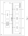
Figure 1 shows a block diagram of an automotive automated driving system to perform low-speed manoeuvres. -
Figure 2 shows an automotive sensory platform of the an automotive automated driving system. -
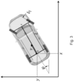
Figure 3 shows inertial and motor-vehicle reference frames for lateral control. -
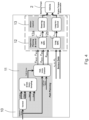
Figure 4 shows a general block diagram of trajectory planning and control for low-speed manoeuvres. -
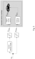
Figure 5 shows a general block diagram of longitudinal control setup. -
Figure 6 shows two low-speed manoeuvres simulated in a virtual environment and physically performed on the road to test the performance of the present invention. -
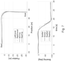
Figure 7 comparatively shows motor-vehicle lateral states during a simulation and a test on road of a first low-speed manoeuvre. -
Figure 8 comparatively shows motor-vehicle longitudinal states during a simulation and a test on road of the first low-speed manoeuvre. -
Figure 9 comparatively shows reference and actuated control inputs during a simulation and a test on road of the first low-speed manoeuvre. -
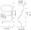
Figure 10 comparatively shows motor-vehicle lateral states during a simulation and a test on road of a second low-speed manoeuvre. -
Figure 11 comparatively shows motor-vehicle longitudinal states during a simulation and a test on road of a second low-speed manoeuvre. -
Figure 12 comparatively shows reference and actuated control inputs during a simulation and a test on road of the second low-speed manoeuvre. -
Figure 13 shows lateral constraints and predicted and travelled trajectories of a motor-vehicle during the second low-speed manoeuvre. - The present invention will now be described in detail with reference to the attached figures to allow a person skilled in the art to make and use it. Various modifications to the described embodiments will be immediately apparent to the persons skilled in the art and the generic principles described can be applied to other embodiments and applications without departing from the protective scope of the present invention, as defined in the attached claims. Therefore, the present invention should not be considered limited to the described and illustrated embodiments, but it must be accorded the widest protective scope in accordance with the described and claimed characteristics.
- Where not defined otherwise, all the technical and scientific terms used herein have the same meaning commonly used by persons skilled in the art pertaining to the present invention. In the event of a conflict, this description, including the definitions provided, will be binding. Furthermore, the examples are provided for illustrative purposes only and as such should not be considered limiting.
- In particular, the block diagrams included in the attached figures and described below are not intended as a representation of structural characteristics or constructive limitations, but must be interpreted as a representation of functional characteristics, i.e. intrinsic properties of the devices and defined by the obtained effects or functional limitations, which can be implemented in different ways so as to protect their functionalities (operating abilities).
- In order to facilitate the understanding of the embodiments described herein, reference will be made to some specific embodiments and a specific language will be used to describe the same. The terminology used in the present document has the purpose of describing only particular embodiments, and is not intended to limit the scope of the present invention.
-
Figure 1 shows a block diagram of an automotive electronicautomated driving system 1 of a motor-vehicle 2 and designed to cause the motor-vehicle 2 to perform low-speed manoeuvres in automated driving. - As shown in
Figure 1 , theautomated driving system 1 comprises: - automotive systems, of which only those involved in the implementation of the present invention will be described below, and comprising, inter alia, an automotive sensory system or
platform 3 designed to detect motor-vehicle-related quantities comprising, by way of example, wheel angle, steering wheel angle, yaw rate, longitudinal and lateral acceleration, position, etc., andautomotive actuators 4 comprising, inter alia, Electric Power Steering (EPS) 5, Braking System Module (BSM) 6, and PoWerTrain (PWT) 7; and - an automotive electronic control unit (ECU) 8 designed to communicate, via an automotive on-
board communication network 9, such as a high-speed CAN, also known as C-CAN, FlexRAy or others, with the automotivesensory platform 3 and theautomotive actuators 4, directly or indirectly, i.e., via dedicated automotive electronic control units, and to store and execute an automated driving software comprising software instructions which, when executed, cause the ECU 8 to become configured to communicate and cooperate with the with the automotivesensory platform 3 and theautomotive actuators 4 to cause the motor-vehicle 2 to perform low-speed manoeuvres in automated driving. - The automotive
sensory platform 3, an exemplary embodiment of which is shown inFigure 2 , may comprise traditional normal production ESC inertial Active Chassis sensors comprising longitudinal and lateral acceleration sensors, yaw rate sensors, and environment sensors including a (dual antenna) GNSS receiver, one or different forward-looking stereo cameras, a normal production forward-looking camera, one or different lidar sensors, one or more radar sensors, and a number of ultrasonic sensors. -
EPS 5 comprises an electric motor operatively coupled to either a steering gear or a steering column and electrically controlled by theECU 8 based on angular position and torque of the steering column sensed by the automotive sensory system orplatform 3 to apply assistive steering torque and, resultingly, provide different amounts of assistance depending on driving conditions. A normal production EPS driven by a traditional Park Assist HWTO (Hand Wheel Torque Overlay) interface on the C-CAN 6 has been modified in terms of maximum motor-vehicle speed to result in the EPS providing not only assistance to the motor-vehicle driver but also a mechatronic unit to steer the motor-vehicle . -
BSM 6 represents a functional interface to realize acceleration and deceleration actions on the motor-vehicle 2. The ECU 8 provides on the C-CAN 9 a functional channel able to be a gateway of acceleration / positive torque to the powertrain ECU (ECM) and the way to decelerate the motor-vehicle 2 by brakes. The normal production parking longitudinal interface has been modified in order to achieve technical targets of present invention. Also Dual Dry Clutch Transmission (DDCT) ECU software has been modified in order to manage the longitudinal manoeuvres from/to 0/15 km/h around to 0 Nm of engine torque in a comfortable way. - The Applicant has experienced that well-known dynamic models currently used for Trajectory Planning and Control for low-speed manoeuvres are undefined or ill-conditioned at low speeds. As shown to be effective in Polack et al., The Kinematic Bicycle Model: a Consistent Model for Planning Feasible Trajectories for Autonomous Vehicles, IEEE Intelligent Vehicles Symposium (IV), 2017, and Kong et al. Kinematic and dynamic vehicle models for autonomous driving control design, in 2015 IEEE Intelligent Vehicles Symposium 2015, pp. 1094-1099, the model used for low speed applications (0÷20 km/h) is the kinematic bicycle model.
- With regard to the lateral motor-vehicle model, the 4-DoF (Degree of Freedom) kinematic bicycle model is one of the simplest models used in motion planning.
Figure 3 shows the inertial and motor-vehicle reference frames for lateral control, in which the two left and right front wheels are represented by one single wheel at point A and the rear wheels are represented by one central rear wheel at point B. - The steering angles of the front and rear wheels are represented by δf and δr , respectively. The model is derived assuming that only the front wheel can be steered (δr =0). For that reason and simplicity, notation δ = δf will be used.
- The resulting kinematic bicycle model may be described by the following state-space equations in the inertial reference frame:


- In particular, x and y are the Cartesian coordinates of the motor-vehicle's rear wheel, while ψ describes the orientation (yaw angle) of the motor-vehicle, v and a denote the velocity and longitudinal acceleration, respectively. Thus, the state and input vectors of this model can be defined as X=[x,y,ψ,v] and U=[δ,a], respectively.
- The described kinematic model is nonlinear, so, as described by Oyama K. et al., Model predictive parking control for non-holonomic vehicles using time-state control form, in 2013 European Control Conference, 458-465, a time-state control form described by Kiyota H. et al., A control of a class of nonholonomic systems with drift using time-state control form, IFAC Nonlinear Control Systems Design, Enschede, The Netherlands, 757-762 (1998), may be used. This approach results in the lateral dynamics being linearized and representable as a differential equation w.r.t. the state (x) instead of time.
- Dividing equations (2) and (3) by (1), a time-state control form is obtained:

- Introducing the non-linear state and input transformation:


- The actual steering angle δ is computed using µ2 and ψ by inverting equation (8):

- With regard to the longitudinal motor-vehicle model, in general, the point-mass model is not used for design lateral controllers due to their large modelling errors. However, those models are widely used for longitudinal control purposes and the motor-vehicle's longitudinal motion is described, in the motor-vehicle reference frame, as a double integrator system:


-
Figure 4 shows a general block diagram of adynamics control system 10 designed to control lateral and longitudinal dynamics of the motor-vehicle 2 during performance of low-speed manoeuvres in automated driving. - The dynamics control
system 10 may be entirely implemented by theECU 8 or its implementation may be distributed among different ECUs, according to a proprietary logical architecture that the automotive manufacturer will decide to adopt. - For ease of description, in the following the
dynamics control system 10 wil be described to be entirely implemented by theECU 8, without thereby this implying any loss of generality. - The dynamics control
system 10 is designed to implement aDriving Path Planner 11 designed to receive data representative of static obstacles, such as roads, buildings, etc., in the surroundings of the motor-vehicle 2 and representing static space constraints to the motion of the motor-vehicle 2, and to compute a planned driving path for the motor-vehicle 2 during a low-speed manoeuvres performed in automated driving based on the positions of the static obstacles in the surroundings of the motor-vehicle 2 by implementing an algorithm fusion between techniques known in the literature, e.g., a Voronoi decomposition and A* path search algorithm. - In particular, the
Driving Path Planner 11 is designed to compute the planned driving path as an obstacle-free driving corridor within which the motor-vehicle 2 may be driven and made up of a series of driving path segments each with a length and an orientation referenced in an inertial (or absolute) reference frame. - The dynamics control
system 10 is further designed to implement a Model Predictive Control (MPC)-based Trajectory Planner andController 12 designed to receive from theDriving Path Planner 11 data representative of the planned driving path of the motor-vehicle 2 and to compute, based thereon, a planned lateral trajectory and a planned longitudinal trajectory of the motor-vehicle 2, as described in more detail in the following. - In particular, the MPC-based Trajectory Planner and
Controller 12 comprises two distinct MPC-based Trajectory Planners and Controllers, a Lateral Trajectory Planner andController 12a designed to plan and control the Lateral dynamics, and a Longitudinal Trajectory Planner andController 12b designed to plan and control the Longitudinal dynamics. - The Lateral Trajectory Planner and
Controller 12a is designed to compute the planned lateral trajectory as a series of steering requests δ along the planned driving path in a motor-vehicle reference frame, and the Longitudinal Trajectory Planner andController 12b is designed to compute the planned longitudinal trajectory as a series of longitudinal acceleration requests a of the motor-vehicle 2 along the planned driving path; - Model Predictive Control (MPC) has been developed considerably over the last two decades. The main advantage of the MPC is the fact that it allows the current timeslot to be optimized while taking future time-slots into account. This is achieved by optimizing a finite time-horizon, but only implementing the first time-slot.
- MPC can manage future reference profiles and constraints and anticipate control actions accordingly. These limits may be imposed on any part of the system variables, such as states, outputs, inputs, and considering main actuators characteristics and operative limitations.
- The dynamics control
system 10 is further designed to implement aMotion Controller 13 designed to receive from the Trajectory Planner andController 12 data representative of the planned lateral a longitudinal trajectories and to compute appropriate commands for theautomated driving system 1, as described in more detail in the following. - From equation (10), in order to control z2 and z3 using µ2 , the MPC-based Lateral Trajectory Planner and
Controller 12a controls the motor-vehicle lateral dynamics to track the optimal path according to constraints on the steering limitation and obstacle-free driving corridor. Discretizing equation (10) by using Tustin method, it may be obtained:
- Denoting the state vector, z= [ z2 z3 ]T, the control horizon, H, the weight diagonal positive definite matrices Q and R, the general performance index for path tracking control may be defined as:


- Considering from equation (11) the function:


- Since it is a nonlinear function of z3 , in order to solve the optimization through linear constraints, it is approximated with a first-order Taylor series expansion:


- Thus, the lateral MPC formulation may be rewritten as:


- The Applicant has noticed that main problems of this approach are the representation singularities introduced by the model outside the range π/2<ψ<π/2 and errors introduced by the linearization.
- The present invention overcomes these problems by dynamically (and smoothly) modifying the relative orientation of the motor-vehicle reference frame and the inertial reference frame along the planned driving path, in particular by dynamically (and smoothly) rotating the motor-vehicle reference frame relative to the inertial reference frame, so as to prevent ψ from being higher than π/2.
- Rotation of the motor-vehicle reference frame relative to the inertial reference frame amounts to a corresponding rotation of the planned driving path relative to inertial reference frame, so resulting in the planned driving path failing to exhibit bends greater than π/2.
- These allow representation singularities to be avoided, whereby reducing linearization errors at each time step, and maximizing the length of the section of path usable by the MPC-based Lateral Trajectory Planner and
Controller 12a. In this way, maximum flexibility of scenario coverage may be obtained. - In detail, after computing the planned driving path of the motor-
vehicle 2 as a set of driving path segments, it is firstly identified in which driving path segment the motor-vehicle 2 is located and then the planned driving path is dynamically rotated using a linear interpolation of the orientation angles θi and θ i+1 of driving path actually driven along by the motor-vehicle 2 and of the first next driving path segment, and a weighting factor W computed based on the orientation angle θi+2 of the second next driving path segment:
- (xv,yv ) are the current motor-vehicle's coordinates in the inertial reference frame,
- d is the Euclidean distance between the current position of the motor-
vehicle 2 and the end of the driving path segment containing the current position of the motor-vehicle 2, and - di+1,i is the length of the next driving path segment following the one containing the current position of the motor-vehicle.
- Like the MPC-based Lateral Trajectory Planner and
Controller 12a, also for MPC-based Longitudinal Trajectory Planner andController 12b the control technique is the linear MPC. This allows speed reference and obstacle tracking to be managed in a single integrated approach. - To implement a control using the motor vehicle's longitudinal motion model, the aforementioned system (12, 13) may be discretised:

vehicle 2 from the start of the planned driving path, v is the longitudinal speed, and Δt is the time step between two computation time instants. - This formulation easily handles problems such as tracking of speed reference and maintenance of position constraints. However, this approach can't handle stationary error due to exogenous disturbances and/or motion control inaccuracy.
- The present invention overcomes this problem by adding a position reference computed as the difference between the integral of the speed reference and Dsmeas , which is the travelled distance measured from longitudinal control enabled by the wheel speed sensors:

- The performance index for speed tracking control can be written as:


- About the speed reference, the general idea is:
- to try to follow the maximum speed allowed along straight driving paths segments, and
- to reduce it taking into account:
- ∘ the curvature ρ predicted by the Lateral Trajectory Planner and
Controller 12a, and - ∘ the maximum allowed lateral acceleration, aymax :

- ∘ the curvature ρ predicted by the Lateral Trajectory Planner and
- The previously-described motor-vehicle models assume that the control inputs, i.e., the series of steering requests δ and the series of longitudinal acceleration requests a, can be directly controlled. However, low level controllers are needed to transform this control inputs into physical signals for the actuators. In detail, the steering angle control is realized by using the EPS torque interface available on the CAN. Similarly, the motor-vehicle longitudinal motion is controlled by means of acceleration/deceleration requests to the braking system through normal production Adaptive Cruise Control interface.
- The EPS low level control loop has been designed by using a state feedback controller comprising:
- a linear time invariant Kalman observer that filters/estimates the system states, useful also to estimate driver hands on the steering wheel, and
- an optimal linear quadratic integral controller able to track the steering wheel angle reference from MPC-based Lateral Trajectory Planner and
Controller 12a. - Further details about a model-based development and related practical considerations may be found in Raffone E. (2016) A Reduced Order Steering State Observer for Automated Steering Control Functions, Proceedings of the 13th Int. Conf. on Informatics in Control, Automation and Robotics, Lisbon, Portugal.
- Conversely to the steering control, the longitudinal acceleration control is managed by multiple actuations (e.g., engine, electric motor, gear-box, and braking), hence the interfaces can change according to the motor-vehicle architecture, actuator controls, and their integration.
- In this case, we face a motor-
vehicle 2 in which the motor-vehicle interfaces, for longitudinal dynamic control, are: - engine-torque request: delivered to Engine Control (Treqs )
- deceleration request: delivered to Brakeing System (areqs )
- With the aim to keep the control architecture simply and easy to tune, no further feedback control loop is introduced at this level. Therefore, the longitudinal acceleration control is implemented by means of the structure shown in
Figure 5 . - The command ax is split in two channels, one for each interface. The Braking System includes a deceleration closed loop that allows to accept directly deceleration command (areqs ) and to generate a braking torque Tbra. The Engine Control performs a closed-loop control based on an estimation of applied engine torque TEng. To match the available interface it has been implemented an inverse vehicle model, to convert ax in Treqs , which considers the current motor-vehicle configuration (e.g., gear ratio, inertia, friction) and mainly exogenous input (e.g. road slope, drag forces).
- The relative equation can be written as follows:

- Performance of the present invention has been tested by simulating and experimenting on road the two low-speed manoeuvres shown in
Figure 6 . - Simulations and tests have been made by setting:
- the MPC of the Lateral Trajectory Planner and
Controller 12a with a prediction horizon (Hlat) equal to 60 steps and step width (Δs) of 0.5 m, and - the MPC of the Longitudinal Trajectory Planner and
Controller 12b with a prediction horizon (Hlong) equal to 40 steps and step width (Δt) of 100 ms. - The prediction step has been chosen to represent a quasi-infinite horizon for motor-vehicle kinematics optimization (about 30 meters or 4 seconds).
- The first low-speed manoeuvre is a curve, trying to maintain the half of the road lane and the motor-vehicle bearing parallel as much as possible to the actual driving path segment orientation (
Figure 7 ). The required longitudinal behaviour expects to track a reference vehicle speed of 10km/h. The lateral controller is able to compute a smooth steering angle reference which satisfies the physical constraints according to equation (16) (Figure 9 ). The lateral prediction is used to realize a deceleration profile proportional to the expected change of orientation (Figure 8 ) to achieve a comfortable manoeuvre. - When the motor-vehicle has reached the goal, it was stopped at a longitudinal position constraint and the longitudinal controller was demanded to realize a comfortable stop manoeuvre.
-
Figure 7 shows an interesting matching between simulation and test on the road, with only limited differences in terms of trajectory and motor-vehicle orientation. The same matching may also be appreciated inFigure 8 , mainly in the travelled distance: significant differences between simulation and test are about motor-vehicle speed, due to the fact that the implemented motor-vehicle model was not so detailed in terms of powertrain hysteresis and non-linearities. - The second low-speed manoeuvre is more challenging than the first one and consisted in an automated valet parking search manoeuvre, with narrow spaces and two consecutive u-curves.
- The second low-speed manoeuvre is shown in
Figures 10 ,11 , and12 , which correspond to Figured 7, 8, and 9 relating to the first low-speed manoeuvre. - Again the matching between simulation and test is impressive in terms of trajectory and bearing. The differences in terms of longitudinal and lateral commands are reasonable. This mismatch is acceptable considering a simulation tool enough complex to represent the vehicle for the model based design, and, at the same time, enough simple to be identified and maintained.
- Besides,
Figure 13 shows the sequence of predicted trajectories at different time steps during the second low-speed manoeuvre. The continuous line shows the trajectory travelled by the motor-vehicle, the dotted lines show the planned trajectories at each timestamp, and the dashed lines show the constraints. It's very impressive to see how the planned trajectory tries to track the references and to keep the defined constraints. The sequence of plots shows also how the optimization solvers have to solve a different problem including, step by step, different path segments and different path segment orientations. This demonstrates the effectiveness of explained approach to solve a non-linear optimization problem with a linear approach based on time state control form (TSCF) transformation.

Claims (6)
- An automotive electronic dynamics control system (10) for a motor-vehicle (2) equipped with an automotive automated driving system (1) designed to cause the motor-vehicle (2) to perform low-speed manoeuvres in automated driving;the automotive automated driving system (1) comprises:- an automotive sensory system (3) designed to sense motor-vehicle-related quantities, and- automotive actuators (4) comprising an Electric Power Steering (5), a Braking System (6), and a Powertrain (7);the electronic dynamics control system (10) is designed to implement:- a Driving Path Planner (11) designed to:∘ receive data representative of static obstacles in the surroundings of the motor-vehicle (2) and representing static space constraints to the motion of the motor-vehicle (2), and∘ compute, based on the received data, a planned driving path for the motor-vehicle (2) during a low-speed manoeuvre performed in automated driving;- a Model Predictive Control (MPC)-based Trajectory Planner and Controller (12) designed to:∘ receive from the Driving Path Planner (11) data representative of the planned driving path and from the automotive sensory system (3) data representative of positions and orientations of the motor-vehicle (2) and of dynamic obstacles in the surroundings of the motor-vehicle (2) and representing dynamic space constraints to the motion of the motor-vehicle (2), and∘ compute, based on the received data, a planned lateral trajectory and a planned longitudinal trajectory for the motor-vehicle (2) during the low-speed manoeuvre performed in automated driving; and- a Motion Controller (13) designed to:∘ receive from the Trajectory Planner and Controller (12) data representative of the planned lateral and longitudinal trajectories, and∘ compute commands for the Electric Power Steering (5) based on the planned lateral trajectory, and for the Braking System (6) and the Powertrain (7) based on the planned longitudinal trajectory;the Driving Path Planner (11) is designed to compute the planned driving path as an obstacle-free driving corridor within which the motor-vehicle (2) may be driven and made up of a series of driving path segments each with a length and an orientation referenced in an inertial reference frame;the MPC-based Trajectory Planner and Controller (12) comprises:- an MPC-based Lateral Trajectory Planner and Controller (12a) designed to compute the planned lateral trajectory as a series of steering requests (δ) referenced in a motor-vehicle reference frame; and- an MPC-based Longitudinal Trajectory Planner and Controller (12b) designed to compute the planned longitudinal trajectory as a series of longitudinal acceleration requests (a);the Lateral Trajectory Planner and Controller (12a) is further designed to compute the planned lateral trajectory based on a linearized Model which exhibits a representation singularity whenever the relative orientation of a couple of successive driving path segments of the planned driving path is equal to or higher than a given amount;the Lateral Trajectory Planner and Controller (12a) is further designed to dynamically modify relative orientation (θROT ) of the motor-vehicle reference frame and the inertial reference frame along the planned driving path to cause the relative orientations of all of the couples of successive driving path segments of the planned driving path to be lower than the given amount.
- The automotive electronic dynamics control system (1) of claim 1, wherein the Lateral Trajectory Planner and Controller (12a) is further designed to compute the orientation (θROT ) of the motor-vehicle reference frame relative to the inertial reference frame based on the orientation (θi ) of the driving path segment currently driven by the motor-vehicle (2) and on the orientation (θ i+1 ) of the next driving path segment.
- The automotive electronic dynamics control system (1) of claim 2, wherein the Lateral Trajectory Planner and Controller (12a) is further designed to compute the orientation (θROT ) of the motor-vehicle reference frame relative to the inertial reference frame also based on the orientation (θ i+2 ) of the second next driving path segment.
- The automotive electronic dynamics control system (1) of claim 3, wherein the Lateral Trajectory Planner and Controller (12a) is further designed to compute the relative orientation of the motor-vehicle reference frame and the inertial reference frame as a linear interpolation of the orientation (θi ) of the driving path segment currently driven by the motor-vehicle (2) and of the orientations (θi+1 , θ i+2 ) of the first and next driving path segments.
- The automotive electronic dynamics control system (1) of claim 4, wherein the Lateral Trajectory Planner and Controller (12a) is further designed to compute the relative orientation of the motor-vehicle reference frame and the inertial reference frame as:
 θROT is the orientation of the motor-vehicle reference frame relative to the inertial reference frame,θi, θi+1, θi+2 are the orientations of the driving path segment currently driven by the motor-vehicle (2), of the first next driving path segment, and of the second next driving path segment in the inertial reference frame,W is a weighting factor,xv ,yv are the current motor-vehicle's coordinates in the inertial reference frame,d is the Euclidean distance between the current position of the motor-vehicle (2) and the end of the driving path segment containing the current position of the motor-vehicle (2), anddi+1,i is the length of the next driving path segment to the one containing the current position of the motor-vehicle (2).
 - Software loadable in an automotive electronic control unit (8) and designed to cause, when executed, the automotive electronic control unit (8) to become configured to implement the automotive electronic dynamics control system (10) as claimed in any one of the preceding claims.
Applications Claiming Priority (3)
| Application Number | Priority Date | Filing Date | Title |
|---|---|---|---|
| EP19204949 | 2019-10-23 | ||
| IT102020000009100A IT202000009100A1 (en) | 2020-04-27 | 2020-04-27 | TRAJECTORY PLANNING AND CONTROL OF AN AUTONOMOUS MOTOR VEHICLE FOR THE REALIZATION OF LOW SPEED MANEUVERING IN AUTONOMOUS DRIVING |
| PCT/IB2020/059987 WO2021079338A1 (en) | 2019-10-23 | 2020-10-23 | Motor-vehicle trajectory planning and control to cause automated motor-vehicles to perform low-speed manoeuvres in automated driving |
Publications (2)
| Publication Number | Publication Date |
|---|---|
| EP4048567A1 EP4048567A1 (en) | 2022-08-31 |
| EP4048567B1 true EP4048567B1 (en) | 2025-04-02 |
Family
ID=73014561
Family Applications (1)
| Application Number | Title | Priority Date | Filing Date |
|---|---|---|---|
| EP20797200.1A Active EP4048567B1 (en) | 2019-10-23 | 2020-10-23 | Motor-vehicle trajectory planning and control to cause automated motor-vehicles to perform low-speed manoeuvres in automated driving |
Country Status (3)
| Country | Link |
|---|---|
| US (1) | US11970157B2 (en) |
| EP (1) | EP4048567B1 (en) |
| WO (1) | WO2021079338A1 (en) |
Families Citing this family (20)
| Publication number | Priority date | Publication date | Assignee | Title |
|---|---|---|---|---|
| US11884302B2 (en) * | 2019-11-15 | 2024-01-30 | Massachusetts Institute Of Technology | Social behavior for autonomous vehicles |
| CN113320542B (en) * | 2021-06-24 | 2022-05-17 | 厦门大学 | A tracking control method for an autonomous vehicle |
| CN113734183B (en) * | 2021-09-17 | 2023-05-02 | 京东鲲鹏(江苏)科技有限公司 | Vehicle control method, device, equipment and storage medium based on steering hysteresis |
| CN113978547B (en) * | 2021-10-21 | 2022-08-02 | 江铃汽车股份有限公司 | Automatic driving steering control method and system |
| CN114139787B (en) * | 2021-11-23 | 2024-12-31 | 北京科技大学 | An optimal trajectory planning method and system for turning at intersections of articulated mining equipment |
| CN114255594B (en) * | 2021-12-28 | 2024-03-15 | 吉林大学 | An autonomous valet parking motion planning and motion control method |
| CN114312847B (en) * | 2022-01-13 | 2024-04-12 | 安徽江淮汽车集团股份有限公司 | Transverse control method and device for automatic driving vehicle |
| CN115214715B (en) * | 2022-03-15 | 2026-05-01 | 广州汽车集团股份有限公司 | Transverse control method and control device for automatic driving of vehicle and vehicle |
| CN114689344B (en) * | 2022-04-19 | 2025-09-05 | 上海测迅汽车科技有限公司 | Intelligent detection device for autonomous driving system |
| CN114924561B (en) * | 2022-05-09 | 2025-05-23 | 重庆大学 | Four-steering-wheel AGV track tracking control method |
| US12145582B2 (en) * | 2022-06-23 | 2024-11-19 | Ford Global Technologies, Llc | Systems and methods for controlling longitudinal acceleration based on lateral objects |
| CN115140098B (en) * | 2022-08-01 | 2025-08-12 | 江西吉利新能源商用车有限公司 | Target locking method, device, equipment and readable storage medium |
| IT202200022308A1 (en) * | 2022-10-28 | 2024-04-28 | Fiat Ricerche | LOW SPEED TRAJECTORY PLANNING BASED ON A PREDICTIVE CONTROL MODEL WITH DYNAMIC OBSTACLE AVOIDANCE IN UNSTRUCTURED ENVIRONMENTS |
| IT202200024234A1 (en) | 2022-11-24 | 2024-05-24 | Fiat Ricerche | LOW SPEED TRAJECTORY PLANNING BASED ON A PREDICTIVE CONTROL MODEL WITH DYNAMIC OBSTACLE AVOIDANCE IN UNSTRUCTURED ENVIRONMENTS |
| IT202200024228A1 (en) | 2022-11-24 | 2024-05-24 | Fiat Ricerche | LOW SPEED TRAJECTORY PLANNING BASED ON A PREDICTIVE CONTROL MODEL WITH DYNAMIC OBSTACLE AVOIDANCE IN UNSTRUCTURED ENVIRONMENTS |
| IT202200024936A1 (en) | 2022-12-02 | 2024-06-02 | Fiat Ricerche | LOW SPEED TRAJECTORY PLANNING BASED ON A PREDICTIVE CONTROL MODEL WITH DYNAMIC OBSTACLE AVOIDANCE IN UNSTRUCTURED ENVIRONMENTS |
| CN116224802B (en) * | 2023-03-31 | 2023-12-05 | 上海理工大学 | Vehicle team longitudinal composite control method based on interference observer and pipeline model prediction |
| CN116540737B (en) * | 2023-06-13 | 2026-02-06 | 吉林大学 | Path planning and control method considering driving habit in static obstacle avoidance scene |
| CN117601857B (en) | 2023-12-18 | 2024-05-10 | 广东工业大学 | A human-machine co-driving switching control method based on trajectory prediction |
| CN120828825A (en) * | 2024-04-22 | 2025-10-24 | 北京魔门塔科技有限公司 | Vehicle control method, device, electronic device and medium |
Family Cites Families (2)
| Publication number | Priority date | Publication date | Assignee | Title |
|---|---|---|---|---|
| US10589739B2 (en) * | 2017-04-13 | 2020-03-17 | GM Global Technology Operations LLC | Automated driving commands interpretation for stability control |
| US20200001920A1 (en) * | 2018-07-02 | 2020-01-02 | Ohio State Innovation Foundation | Systems and methods for preventing a jackknife condition in a tractor-trailer system |
-
2020
- 2020-10-23 EP EP20797200.1A patent/EP4048567B1/en active Active
- 2020-10-23 US US17/442,379 patent/US11970157B2/en active Active
- 2020-10-23 WO PCT/IB2020/059987 patent/WO2021079338A1/en not_active Ceased
Also Published As
| Publication number | Publication date |
|---|---|
| EP4048567A1 (en) | 2022-08-31 |
| US11970157B2 (en) | 2024-04-30 |
| WO2021079338A1 (en) | 2021-04-29 |
| US20220169247A1 (en) | 2022-06-02 |
Similar Documents
| Publication | Publication Date | Title |
|---|---|---|
| US11970157B2 (en) | Motor-vehicle trajectory planning and control to cause automated motor-vehicles to perform low-speed manoeuvres in automated driving | |
| EP4031428B1 (en) | Model-based design of trajectory planning and control for automated motor-vehicles in a dynamic environment | |
| Li et al. | Advanced motion control and sensing for intelligent vehicles | |
| Hatipoglu et al. | Automated lane change controller design | |
| Gao et al. | Predictive control of autonomous ground vehicles with obstacle avoidance on slippery roads | |
| Ferrara et al. | Second order sliding mode control of vehicles with distributed collision avoidance capabilities | |
| Attia et al. | Coupled longitudinal and lateral control strategy improving lateral stability for autonomous vehicle | |
| Caporale et al. | Towards the design of robotic drivers for full-scale self-driving racing cars | |
| US12576907B2 (en) | Model predictive brake-to-steer control for automated vehicles | |
| CN108717268A (en) | The fastest maneuvering control system and control method for automatic driving based on optimal control and safety distance | |
| Koga et al. | Realization of different driving characteristics for autonomous vehicle by using model predictive control | |
| KR20230166124A (en) | Method for autonomously driving actuators of a device | |
| Smith et al. | Effects of model complexity on the performance of automated vehicle steering controllers: controller development and evaluation | |
| Bouzidi et al. | Interaction-aware merging in mixed traffic with integrated game-theoretic predictive control and inverse differential game | |
| Sattel et al. | Ground vehicle guidance along collision-free trajectories using elastic bands | |
| US12371009B2 (en) | Method for automated steering of a motor vehicle | |
| Kim et al. | Experimental verification of the power slide driving technique for control strategy of autonomous race cars | |
| Nilsson et al. | Driver model based automated driving of long vehicle combinations in emulated highway traffic | |
| EP4608699A1 (en) | Model predictive control-based, low-speed trajectory planning with dynamic obstacle avoidance in unstructured environments | |
| Borrello et al. | Trajectory Planning and Vehicle Control at low speed for home zone manoeuvres | |
| Borrello et al. | Trajectory planning based on model predictive control with dynamic obstacle avoidance in unstructured environments | |
| Trotta et al. | A feedback linearization based approach for fully autonomous adaptive cruise control | |
| Ghumman et al. | Guidance-based on-line motion planning for autonomous highway overtaking | |
| Kranz et al. | Nonlinear lateral vehicle control in combined emergency steering and braking maneuvers | |
| Chen et al. | Integrated forward and reverse trajectory tracking control for car-like ground vehicle |
Legal Events
| Date | Code | Title | Description |
|---|---|---|---|
| STAA | Information on the status of an ep patent application or granted ep patent |
Free format text: STATUS: UNKNOWN |
|
| STAA | Information on the status of an ep patent application or granted ep patent |
Free format text: STATUS: THE INTERNATIONAL PUBLICATION HAS BEEN MADE |
|
| PUAI | Public reference made under article 153(3) epc to a published international application that has entered the european phase |
Free format text: ORIGINAL CODE: 0009012 |
|
| STAA | Information on the status of an ep patent application or granted ep patent |
Free format text: STATUS: REQUEST FOR EXAMINATION WAS MADE |
|
| 17P | Request for examination filed |
Effective date: 20210917 |
|
| AK | Designated contracting states |
Kind code of ref document: A1 Designated state(s): AL AT BE BG CH CY CZ DE DK EE ES FI FR GB GR HR HU IE IS IT LI LT LU LV MC MK MT NL NO PL PT RO RS SE SI SK SM TR |
|
| DAV | Request for validation of the european patent (deleted) | ||
| DAX | Request for extension of the european patent (deleted) | ||
| STAA | Information on the status of an ep patent application or granted ep patent |
Free format text: STATUS: EXAMINATION IS IN PROGRESS |
|
| 17Q | First examination report despatched |
Effective date: 20230616 |
|
| GRAP | Despatch of communication of intention to grant a patent |
Free format text: ORIGINAL CODE: EPIDOSNIGR1 |
|
| STAA | Information on the status of an ep patent application or granted ep patent |
Free format text: STATUS: GRANT OF PATENT IS INTENDED |
|
| INTG | Intention to grant announced |
Effective date: 20241105 |
|
| RIC1 | Information provided on ipc code assigned before grant |
Ipc: B62D 15/02 20060101ALI20241025BHEP Ipc: G05D 1/00 20060101ALI20241025BHEP Ipc: B60W 50/00 20060101ALI20241025BHEP Ipc: B60W 30/06 20060101AFI20241025BHEP |
|
| GRAS | Grant fee paid |
Free format text: ORIGINAL CODE: EPIDOSNIGR3 |
|
| GRAA | (expected) grant |
Free format text: ORIGINAL CODE: 0009210 |
|
| STAA | Information on the status of an ep patent application or granted ep patent |
Free format text: STATUS: THE PATENT HAS BEEN GRANTED |
|
| AK | Designated contracting states |
Kind code of ref document: B1 Designated state(s): AL AT BE BG CH CY CZ DE DK EE ES FI FR GB GR HR HU IE IS IT LI LT LU LV MC MK MT NL NO PL PT RO RS SE SI SK SM TR |
|
| REG | Reference to a national code |
Ref country code: GB Ref legal event code: FG4D |
|
| REG | Reference to a national code |
Ref country code: CH Ref legal event code: EP |
|
| REG | Reference to a national code |
Ref country code: IE Ref legal event code: FG4D |
|
| REG | Reference to a national code |
Ref country code: DE Ref legal event code: R096 Ref document number: 602020048808 Country of ref document: DE |
|
| REG | Reference to a national code |
Ref country code: NL Ref legal event code: MP Effective date: 20250402 |
|
| PG25 | Lapsed in a contracting state [announced via postgrant information from national office to epo] |
Ref country code: NL Free format text: LAPSE BECAUSE OF FAILURE TO SUBMIT A TRANSLATION OF THE DESCRIPTION OR TO PAY THE FEE WITHIN THE PRESCRIBED TIME-LIMIT Effective date: 20250402 |
|
| REG | Reference to a national code |
Ref country code: AT Ref legal event code: MK05 Ref document number: 1781031 Country of ref document: AT Kind code of ref document: T Effective date: 20250402 |
|
| PG25 | Lapsed in a contracting state [announced via postgrant information from national office to epo] |
Ref country code: FI Free format text: LAPSE BECAUSE OF FAILURE TO SUBMIT A TRANSLATION OF THE DESCRIPTION OR TO PAY THE FEE WITHIN THE PRESCRIBED TIME-LIMIT Effective date: 20250402 Ref country code: ES Free format text: LAPSE BECAUSE OF FAILURE TO SUBMIT A TRANSLATION OF THE DESCRIPTION OR TO PAY THE FEE WITHIN THE PRESCRIBED TIME-LIMIT Effective date: 20250402 Ref country code: PT Free format text: LAPSE BECAUSE OF FAILURE TO SUBMIT A TRANSLATION OF THE DESCRIPTION OR TO PAY THE FEE WITHIN THE PRESCRIBED TIME-LIMIT Effective date: 20250804 |
|
| REG | Reference to a national code |
Ref country code: LT Ref legal event code: MG9D |
|
| PG25 | Lapsed in a contracting state [announced via postgrant information from national office to epo] |
Ref country code: NO Free format text: LAPSE BECAUSE OF FAILURE TO SUBMIT A TRANSLATION OF THE DESCRIPTION OR TO PAY THE FEE WITHIN THE PRESCRIBED TIME-LIMIT Effective date: 20250702 Ref country code: GR Free format text: LAPSE BECAUSE OF FAILURE TO SUBMIT A TRANSLATION OF THE DESCRIPTION OR TO PAY THE FEE WITHIN THE PRESCRIBED TIME-LIMIT Effective date: 20250703 |
|
| PG25 | Lapsed in a contracting state [announced via postgrant information from national office to epo] |
Ref country code: PL Free format text: LAPSE BECAUSE OF FAILURE TO SUBMIT A TRANSLATION OF THE DESCRIPTION OR TO PAY THE FEE WITHIN THE PRESCRIBED TIME-LIMIT Effective date: 20250402 |
|
| PG25 | Lapsed in a contracting state [announced via postgrant information from national office to epo] |
Ref country code: BG Free format text: LAPSE BECAUSE OF FAILURE TO SUBMIT A TRANSLATION OF THE DESCRIPTION OR TO PAY THE FEE WITHIN THE PRESCRIBED TIME-LIMIT Effective date: 20250402 |
|
| PG25 | Lapsed in a contracting state [announced via postgrant information from national office to epo] |
Ref country code: HR Free format text: LAPSE BECAUSE OF FAILURE TO SUBMIT A TRANSLATION OF THE DESCRIPTION OR TO PAY THE FEE WITHIN THE PRESCRIBED TIME-LIMIT Effective date: 20250402 |
|
| PG25 | Lapsed in a contracting state [announced via postgrant information from national office to epo] |
Ref country code: AT Free format text: LAPSE BECAUSE OF FAILURE TO SUBMIT A TRANSLATION OF THE DESCRIPTION OR TO PAY THE FEE WITHIN THE PRESCRIBED TIME-LIMIT Effective date: 20250402 |
|
| PGFP | Annual fee paid to national office [announced via postgrant information from national office to epo] |
Ref country code: FR Payment date: 20250923 Year of fee payment: 6 |
|
| PG25 | Lapsed in a contracting state [announced via postgrant information from national office to epo] |
Ref country code: RS Free format text: LAPSE BECAUSE OF FAILURE TO SUBMIT A TRANSLATION OF THE DESCRIPTION OR TO PAY THE FEE WITHIN THE PRESCRIBED TIME-LIMIT Effective date: 20250702 |
|
| PG25 | Lapsed in a contracting state [announced via postgrant information from national office to epo] |
Ref country code: IS Free format text: LAPSE BECAUSE OF FAILURE TO SUBMIT A TRANSLATION OF THE DESCRIPTION OR TO PAY THE FEE WITHIN THE PRESCRIBED TIME-LIMIT Effective date: 20250802 |
|
| PG25 | Lapsed in a contracting state [announced via postgrant information from national office to epo] |
Ref country code: LV Free format text: LAPSE BECAUSE OF FAILURE TO SUBMIT A TRANSLATION OF THE DESCRIPTION OR TO PAY THE FEE WITHIN THE PRESCRIBED TIME-LIMIT Effective date: 20250402 |
|
| REG | Reference to a national code |
Ref country code: DE Ref legal event code: R097 Ref document number: 602020048808 Country of ref document: DE |
|
| PGFP | Annual fee paid to national office [announced via postgrant information from national office to epo] |
Ref country code: DE Payment date: 20250923 Year of fee payment: 6 |
|
| PG25 | Lapsed in a contracting state [announced via postgrant information from national office to epo] |
Ref country code: DK Free format text: LAPSE BECAUSE OF FAILURE TO SUBMIT A TRANSLATION OF THE DESCRIPTION OR TO PAY THE FEE WITHIN THE PRESCRIBED TIME-LIMIT Effective date: 20250402 Ref country code: SM Free format text: LAPSE BECAUSE OF FAILURE TO SUBMIT A TRANSLATION OF THE DESCRIPTION OR TO PAY THE FEE WITHIN THE PRESCRIBED TIME-LIMIT Effective date: 20250402 |
|
| PG25 | Lapsed in a contracting state [announced via postgrant information from national office to epo] |
Ref country code: CZ Free format text: LAPSE BECAUSE OF FAILURE TO SUBMIT A TRANSLATION OF THE DESCRIPTION OR TO PAY THE FEE WITHIN THE PRESCRIBED TIME-LIMIT Effective date: 20250402 |
|
| PG25 | Lapsed in a contracting state [announced via postgrant information from national office to epo] |
Ref country code: EE Free format text: LAPSE BECAUSE OF FAILURE TO SUBMIT A TRANSLATION OF THE DESCRIPTION OR TO PAY THE FEE WITHIN THE PRESCRIBED TIME-LIMIT Effective date: 20250402 |
|
| PG25 | Lapsed in a contracting state [announced via postgrant information from national office to epo] |
Ref country code: SK Free format text: LAPSE BECAUSE OF FAILURE TO SUBMIT A TRANSLATION OF THE DESCRIPTION OR TO PAY THE FEE WITHIN THE PRESCRIBED TIME-LIMIT Effective date: 20250402 |
|
| PG25 | Lapsed in a contracting state [announced via postgrant information from national office to epo] |
Ref country code: IT Free format text: LAPSE BECAUSE OF FAILURE TO SUBMIT A TRANSLATION OF THE DESCRIPTION OR TO PAY THE FEE WITHIN THE PRESCRIBED TIME-LIMIT Effective date: 20250402 |
|
| PLBE | No opposition filed within time limit |
Free format text: ORIGINAL CODE: 0009261 |
|
| STAA | Information on the status of an ep patent application or granted ep patent |
Free format text: STATUS: NO OPPOSITION FILED WITHIN TIME LIMIT |
|
| PG25 | Lapsed in a contracting state [announced via postgrant information from national office to epo] |
Ref country code: RO Free format text: LAPSE BECAUSE OF FAILURE TO SUBMIT A TRANSLATION OF THE DESCRIPTION OR TO PAY THE FEE WITHIN THE PRESCRIBED TIME-LIMIT Effective date: 20250402 |
|
| REG | Reference to a national code |
Ref country code: CH Ref legal event code: L10 Free format text: ST27 STATUS EVENT CODE: U-0-0-L10-L00 (AS PROVIDED BY THE NATIONAL OFFICE) Effective date: 20260211 |
|
| 26N | No opposition filed |
Effective date: 20260105 |