EP4048337B1 - Verteiler für dialysemaschinen und gerät und dialysemaschine oder gerät mit diesem verteiler - Google Patents
Verteiler für dialysemaschinen und gerät und dialysemaschine oder gerät mit diesem verteiler Download PDFInfo
- Publication number
- EP4048337B1 EP4048337B1 EP19818249.5A EP19818249A EP4048337B1 EP 4048337 B1 EP4048337 B1 EP 4048337B1 EP 19818249 A EP19818249 A EP 19818249A EP 4048337 B1 EP4048337 B1 EP 4048337B1
- Authority
- EP
- European Patent Office
- Prior art keywords
- manifold
- circulation
- multilayered body
- fluids
- circuit
- Prior art date
- Legal status (The legal status is an assumption and is not a legal conclusion. Google has not performed a legal analysis and makes no representation as to the accuracy of the status listed.)
- Active
Links
Images


Classifications
-
- A—HUMAN NECESSITIES
- A61—MEDICAL OR VETERINARY SCIENCE; HYGIENE
- A61M—DEVICES FOR INTRODUCING MEDIA INTO, OR ONTO, THE BODY; DEVICES FOR TRANSDUCING BODY MEDIA OR FOR TAKING MEDIA FROM THE BODY; DEVICES FOR PRODUCING OR ENDING SLEEP OR STUPOR
- A61M1/00—Suction or pumping devices for medical purposes; Devices for carrying-off, for treatment of, or for carrying-over, body-liquids; Drainage systems
- A61M1/14—Dialysis systems; Artificial kidneys; Blood oxygenators ; Reciprocating systems for treatment of body fluids, e.g. single needle systems for hemofiltration or pheresis
- A61M1/16—Dialysis systems; Artificial kidneys; Blood oxygenators ; Reciprocating systems for treatment of body fluids, e.g. single needle systems for hemofiltration or pheresis with membranes
-
- A—HUMAN NECESSITIES
- A61—MEDICAL OR VETERINARY SCIENCE; HYGIENE
- A61M—DEVICES FOR INTRODUCING MEDIA INTO, OR ONTO, THE BODY; DEVICES FOR TRANSDUCING BODY MEDIA OR FOR TAKING MEDIA FROM THE BODY; DEVICES FOR PRODUCING OR ENDING SLEEP OR STUPOR
- A61M1/00—Suction or pumping devices for medical purposes; Devices for carrying-off, for treatment of, or for carrying-over, body-liquids; Drainage systems
- A61M1/14—Dialysis systems; Artificial kidneys; Blood oxygenators ; Reciprocating systems for treatment of body fluids, e.g. single needle systems for hemofiltration or pheresis
- A61M1/15—Dialysis systems; Artificial kidneys; Blood oxygenators ; Reciprocating systems for treatment of body fluids, e.g. single needle systems for hemofiltration or pheresis with a cassette forming partially or totally the flow circuit for the treating fluid, e.g. the dialysate fluid circuit or the treating gas circuit
- A61M1/156—Constructional details of the cassette, e.g. specific details on material or shape
- A61M1/1562—Details of incorporated reservoirs
-
- A—HUMAN NECESSITIES
- A61—MEDICAL OR VETERINARY SCIENCE; HYGIENE
- A61M—DEVICES FOR INTRODUCING MEDIA INTO, OR ONTO, THE BODY; DEVICES FOR TRANSDUCING BODY MEDIA OR FOR TAKING MEDIA FROM THE BODY; DEVICES FOR PRODUCING OR ENDING SLEEP OR STUPOR
- A61M1/00—Suction or pumping devices for medical purposes; Devices for carrying-off, for treatment of, or for carrying-over, body-liquids; Drainage systems
- A61M1/14—Dialysis systems; Artificial kidneys; Blood oxygenators ; Reciprocating systems for treatment of body fluids, e.g. single needle systems for hemofiltration or pheresis
- A61M1/28—Peritoneal dialysis ; Other peritoneal treatment, e.g. oxygenation
-
- A—HUMAN NECESSITIES
- A61—MEDICAL OR VETERINARY SCIENCE; HYGIENE
- A61M—DEVICES FOR INTRODUCING MEDIA INTO, OR ONTO, THE BODY; DEVICES FOR TRANSDUCING BODY MEDIA OR FOR TAKING MEDIA FROM THE BODY; DEVICES FOR PRODUCING OR ENDING SLEEP OR STUPOR
- A61M1/00—Suction or pumping devices for medical purposes; Devices for carrying-off, for treatment of, or for carrying-over, body-liquids; Drainage systems
- A61M1/36—Other treatment of blood in a by-pass of the natural circulatory system, e.g. temperature adaptation, irradiation ; Extra-corporeal blood circuits
- A61M1/3621—Extra-corporeal blood circuits
- A61M1/3622—Extra-corporeal blood circuits with a cassette forming partially or totally the blood circuit
- A61M1/36223—Extra-corporeal blood circuits with a cassette forming partially or totally the blood circuit the cassette being adapted for heating or cooling the blood
-
- A—HUMAN NECESSITIES
- A61—MEDICAL OR VETERINARY SCIENCE; HYGIENE
- A61M—DEVICES FOR INTRODUCING MEDIA INTO, OR ONTO, THE BODY; DEVICES FOR TRANSDUCING BODY MEDIA OR FOR TAKING MEDIA FROM THE BODY; DEVICES FOR PRODUCING OR ENDING SLEEP OR STUPOR
- A61M1/00—Suction or pumping devices for medical purposes; Devices for carrying-off, for treatment of, or for carrying-over, body-liquids; Drainage systems
- A61M1/36—Other treatment of blood in a by-pass of the natural circulatory system, e.g. temperature adaptation, irradiation ; Extra-corporeal blood circuits
- A61M1/3621—Extra-corporeal blood circuits
- A61M1/3623—Means for actively controlling temperature of blood
-
- A—HUMAN NECESSITIES
- A61—MEDICAL OR VETERINARY SCIENCE; HYGIENE
- A61M—DEVICES FOR INTRODUCING MEDIA INTO, OR ONTO, THE BODY; DEVICES FOR TRANSDUCING BODY MEDIA OR FOR TAKING MEDIA FROM THE BODY; DEVICES FOR PRODUCING OR ENDING SLEEP OR STUPOR
- A61M2205/00—General characteristics of the apparatus
- A61M2205/12—General characteristics of the apparatus with interchangeable cassettes forming partially or totally the fluid circuit
-
- A—HUMAN NECESSITIES
- A61—MEDICAL OR VETERINARY SCIENCE; HYGIENE
- A61M—DEVICES FOR INTRODUCING MEDIA INTO, OR ONTO, THE BODY; DEVICES FOR TRANSDUCING BODY MEDIA OR FOR TAKING MEDIA FROM THE BODY; DEVICES FOR PRODUCING OR ENDING SLEEP OR STUPOR
- A61M2205/00—General characteristics of the apparatus
- A61M2205/33—Controlling, regulating or measuring
- A61M2205/3317—Electromagnetic, inductive or dielectric measuring means
-
- A—HUMAN NECESSITIES
- A61—MEDICAL OR VETERINARY SCIENCE; HYGIENE
- A61M—DEVICES FOR INTRODUCING MEDIA INTO, OR ONTO, THE BODY; DEVICES FOR TRANSDUCING BODY MEDIA OR FOR TAKING MEDIA FROM THE BODY; DEVICES FOR PRODUCING OR ENDING SLEEP OR STUPOR
- A61M2205/00—General characteristics of the apparatus
- A61M2205/33—Controlling, regulating or measuring
- A61M2205/3331—Pressure; Flow
-
- A—HUMAN NECESSITIES
- A61—MEDICAL OR VETERINARY SCIENCE; HYGIENE
- A61M—DEVICES FOR INTRODUCING MEDIA INTO, OR ONTO, THE BODY; DEVICES FOR TRANSDUCING BODY MEDIA OR FOR TAKING MEDIA FROM THE BODY; DEVICES FOR PRODUCING OR ENDING SLEEP OR STUPOR
- A61M2205/00—General characteristics of the apparatus
- A61M2205/33—Controlling, regulating or measuring
- A61M2205/3368—Temperature
Definitions
- Dialysis treatments in particular, hemodialysis ones, are widely used in medicine for the extracorporeal removal of harmful substances and/or impurities from the blood such as creatinine and urea, in patients suffering from more or less severe kidney failure.
- kidney failure is a disease widespread on a global scale, in particular in the western world, and in constant growth, even in developing countries and/or geographical areas in which a steady growth is recorded in pathologies attributable to an improved life standard such as diabetes, obesity and the like.
- a typical dialysis treatment involves, among other things, the extracorporeal removal of harmful substances and/or impurities from the blood by means of extracorporeal filtering of the blood itself, as well as the removal of excess liquids, such as urine or the like, from the blood, and therefore, ultimately, the extracorporeal circulation of blood and/or other liquids, for example used for adding to the blood substances which it is lacking; since the dialysis treatments represent a practice which is consolidated and known to the skilled in the art, a detailed description is omitted for synthesis purposes.
- a conventional dialysis machine or equipment must therefore inevitably comprise a plurality of component parts adapted to allow the circulation and/or the extracorporeal circulation of the blood and/or other liquids; by way of non-limiting example, pumps, tanks, filters, valves (two-way or three-way), as well as a plurality of sensors are included in the component parts typically present in a dialysis machine or equipment, such as, for example, flow and/or pressure and/or temperature and/or conductivity sensors, the latter being provided for monitoring the different parameters of both the patient and the equipment.
- the aforesaid component parts must be mutually connected to define, precisely, an extracorporeal circuit, wherein the connection of the aforesaid component parts, according to the most commonly adopted solutions, provides for the use of tubing (for example, flexible silicone tubes), joints and similar connecting components.
- tubing for example, flexible silicone tubes
- a first drawback relates to the fact that, for the realization of the one or more extracorporeal circuits, the use of a not negligible quantity of tubing, usually flexible silicone tubes, is required.
- each tubing section represents a possible risk factor, being the tubing subject to wear and therefore to the formation of leaks, the tubing further being at risk of accidental disconnection.
- US 2017/246373 A1 , US 2015/165105 A1 and US 2011/108474 A1 disclose disposable of the known type, adapted to be used into dialysis machine and comprising a rigid portion and a flexible part associated to the rigid portion.
- the present invention is based on the general consideration according to which the issues or disadvantages observed in machines of the known type may be overcome or at least minimized (thus reaching at the same time the intended objects mentioned above), by replacing, at least for the most part, the flexible tubing of machines or equipment of a known type by means of a manifold which defines therein at least part of the extracorporeal circuits defined as a whole by the machine.
- the use of the manifold further allows greatly reducing both the weight and the bulk of the machine or equipment, thus making it easily transportable and usable by the patients themselves and without the assistance of specialized personnel. Furthermore, the use of the manifold allows drastically reducing both management and use costs as well as maintenance costs, the use of the manifold allowing in fact the reduction of maintenance and/or assistance interventions.
- manifold is suitable to be used also in different types of machines and equipment, thus making it possible to standardize manufacturing and assembly steps.
- the present invention relates to a manifold for dialysis machines and/or equipment according to claim 1 and a dialysis machine or equipment according to claim 12.
- the manifold for the circulation of fluids along predetermined circulation paths or circuits in particular, for extracorporeal dialysis machines, comprises a main body with a plurality of inner channels mutually connected to define said predetermined circulation paths, said predetermined circulation paths communicating with the exterior of said main body by means of at least one inlet and at least one outlet adapted to be connected with component parts and/or tubing of a extracorporeal dialysis machine, said main body comprising a first outer multilayered body, an intermediate multilayered body superimposed on said first outer multilayered body and a second outer multilayered body superimposed on said intermediate multilayered body on the opposite part with respect to said first outer multilayered body, said three bodies being mutually rigidly fastened, wherein the first outer multilayered body has at least a first groove extending both from the surface thereof in contact with the intermediate multilayered body by a depth lower than the whole thickness thereof, as well as perpendicularly to said thickness, wherein said intermediate multilayered body has at least a second groove at said first groove of the first outer
- said first outer multilayered body has at least a first through hole extending between the outer surface of said first outer multilayered body opposite to the surface in contact with said intermediate multilayered body and said first groove of said first outer multilayered body, said first through hole thus putting in communication with the exterior a channel or a portion thereof of said plurality of inner channels.
- said at least a first through hole of said first outer multilayered body defines a seat in which a monitoring component of said circulation of fluids is housed as a pressure and/or temperature and/or conductivity and/or flow sensor, wherein, in said seat the respective monitoring component is housed so as to be in interference with the flow of said fluids in said inner channel or portion thereof.
- said first outer multilayered body has a plurality of said first through holes positioned each so as to put in communication with the exterior a channel or a portion thereof of said plurality of inner channels, wherein at least two of said first through holes of said first outer multilayered body define each a seat in which a monitoring component of said circulation of fluids is housed as a pressure and/or temperature and/or conductivity and/or flow sensor, and wherein, in each of said at least two seats, the respective monitoring component is housed so as to be in interference with the flow of said liquids.
- the respective component in at least one of said seats, is housed so as to be accessible from the exterior.
- At least two of said plurality of first through holes of said first outer multilayered body define an inlet and an outlet, respectively, for the introduction and the discharge of said fluids, respectively, into and from an inner channel or a portion thereof, respectively.
- said inlet and/or said outlet are shaped so as to be put in fluid communication with component parts of a dialysis machine such as, for example, pumps, and/or filters, and/or tanks, and/or tubing and/or the like.
- a connecting tube is housed in at least said inlet and/or said outlet.
- said main body has at least a first and a second circulation circuit or path, each connected to the exterior by means of an inlet and an outlet defined by corresponding through holes of said first outer multilayered body.
- said first and second circulation circuits or paths have a common section.
- the dialysis machine comprises means adapted to allow the extracorporeal circulation of fluids, such as blood, dialyzing solutions, saline solutions and the like, along pre-determined circulation circuits or paths, said circulation circuits or paths being defined at least partially by a manifold according to one of the embodiments summarized above.
- fluids such as blood, dialyzing solutions, saline solutions and the like
- said manifold defines at least a first circulation circuit or path whose inlet is connectable to the water mains, wherein at least one pressure sensor and at least one pressure regulator are arranged along said at least a first circulation circuit or path.
- said at least a first circulation circuit or path is connected to a tank so as to allow the introduction of fluids from said at least a first circuit to said tank and the re-introduction of fluids from said tank into said at least a first circuit.
- one or more flow and/or conductivity and/or pressure sensors are arranged along said at least a first circulation circuit or path, downstream of said tank.
- said manifold defines at least a second circulation circuit or path connected to said tank so as to allow the introduction of fluids from said at least a second circuit to said tank and the re-introduction of fluids from said tank into said at least a second circuit.
- said manifold defines at least one third circulation circuit or path connected both to said tank and to a bicarbonate cartridge, wherein said at least one third circuit is such as to allow the introduction of liquids from said tank to said cartridge and the discharge of liquids from said cartridge.
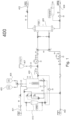
- FIG. 1 shows the hydraulic diagram of a dialysis machine according to an embodiment of the present invention.
- the machine 400 comprises an entry or inlet 401 for the introduction of water from the water mains, an outlet 402 for the post-treatment discharge of dialysis liquids, an entry or inlet 404 connectable to the patient for the introduction into the machine 400 of the untreated blood of the patient him or herself, and an outlet 403 connectable to the patient for the post-treatment re-introduction of the treated blood into the body of the patient him or herself.
- the machine 400 further comprises canonical and conventional components of dialysis machines, such as, for example, tanks 405, 406, 407 and 408 for liquids, a filter 409 and a bicarbonate cartridge 410.
- the aforesaid canonical components are mutually connected by means of liquid circulation circuits or paths, along which both active components are arranged, such as pumps, valves (one-way and/or two-way and/or three-way) and the like, for moving said liquids, as well as passive components, such as monitoring and/or control components, for example, pressure, temperature, conductivity, flow sensors etc.
- the components of the machine 400 are mutually connected by means of circuits or paths for the circulation of liquids (blood, water, solutions etc.) at least in part defined by a manifold according to the following methods.
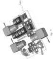
- a manifold 200 and three multilayered bodies 1, 2 and 3 are shown therein which are mutually superimposed and connected (for example, but not exclusively, by means of screws 101, as shown) to form the manifold 200.
- the manifold 200 further has, therein, a plurality of channels 102 mutually connected to define the aforesaid circulation paths or circuits, said channels being in fluid communication with the exterior by means of at least one inlet and/or outlet connected to the component parts of the machine which are not housed in the manifold 200, for example, to one or more of the tanks and/or filters and/or cartridges and/or pump valves of Figure 1 , the passive components of the machine (sensors or the like) 400 being on the contrary at least in part housed in the manifold 200 according to the methods explained below.
- the manifold 200 comprises a first outer multilayered body 1, an intermediate multilayered body 2 superimposed on said first outer multilayered body 1 and a second outer multilayered body 3 superimposed on said intermediate multilayered body 2 on a part opposite with respect to said first outer multilayered body 1, said three bodies being mutually rigidly fastened, for example, but not necessarily, by means of screws 101; with regard to the intermediate multilayered body 2, the same may be made of adhesive material to act both as a glue and as a gasket between the outer multilayered bodies 1 and 3.
- the intermediate body 2 may be omitted and the bodies 1 and 3 may be mutually fastened by means of different solutions, for example, by means of laser or ultrasound welding.
- the first outer multilayered body 1 has at least one plurality of first grooves or depressions 102 (only one shown in Figure 5a ) mutually connected to form one or more channels and/or paths and/or circuits for the circulation of liquids, wherein each first groove 102 extends both from the surface 103 of the outer body 1 in contact with the intermediate multilayered body 2 by a depth lower than the whole thickness S thereof, as well as perpendicularly to said thickness, and therefore perpendicularly to the plane of Figure 6a .
- each second groove 202 extends both for the entire thickness s of said intermediate multilayered body 2 in a passing-through manner, as well as perpendicularly to said thickness s (to the plane of Figure 6a ), the first 102 and the second grooves 202 thus defining inner circulation channels of said fluids, wherein each said second through groove (202), from the opposite part to said first multilayered body 1, is closed by said second outer multilayered body 3, also called top.
- Figure 2b shows a top plan view (from above with respect to Figure 6a ) of the first outer multilayered body 1 sectioned at the height of the first grooves 102 (section A-A of Figure 6a ) and clearly shows the first grooves 102 connected to form the aforesaid circulation circuits or paths for fluids or liquids (see the following description). Furthermore, the outer layer 1, at said first grooves 102, and along the path thereof, has one or more wells 104 by means of which the first grooves 102 are placed in fluid communication with the exterior of the manifold.
- Each said well or hole 104 extends, in fact, between the upper surface 105 of the multilayered body 1 and a respective first groove, wherein, therefore, each well or hole 104 may be used as an inlet and respectively as an outlet for the introduction of liquids into the groove 102 (and therefore in the corresponding circulation channel or circuit) and respectively for the discharge of the liquids from the groove 102 (and therefore from the corresponding channel or circuit).
- the wells or holes 104 are therefore shaped so as to be connected with component parts of a dialysis machine which are exterior to the manifold (valves, pumps, tanks and the like), wherein, for the purpose, according to an embodiment of the present invention, in each well or hole 104 a flexible connecting tube 106, for example made of silicone, is arranged.
- the outer multilayered body 1 has a plurality of second wells 107 arranged along the first grooves 102, said second wells 107 each defining a seat for housing respective control and/or monitoring components 12, for example, pressure and/or flow and/or temperature and/or conductivity sensors and/or the like, arranged in the respective housing seats 107 so as to be at least in partial flow interference with the liquid in the underlying groove 102.
- respective control and/or monitoring components 12 for example, pressure and/or flow and/or temperature and/or conductivity sensors and/or the like
- the second wells 107 may either be dead towards the surface 105 of the multilayered body 1, or open and therefore extend from the respective first groove 102 until surfacing from the surface 105, thereby making the access from the exterior of the manifold to the respective component 12 housed therein possible.
- Figures 1 , 2a and 2b a description will be given below of two liquid circulation circuits defined at least in part by a manifold according to an embodiment of the present invention and therefore obtained therein according to the methods clarified above.
- the first circuit comprises two sections or sub-circuits, respectively shown in the Figures by means of a dotted line (first sub-circuit) and a broken line (second sub-circuit).
- water is drawn, for example, from a hospital network (point 0) and then conveyed along the first section of the sub-circuit, where a pressure sensor, a pressure regulator ( Figure 2a ), bringing the network pressure from 2-3 bars to 1 bar, and a two-way valve are inserted.
- the water is then conveyed to point 1 which is the tank, wherein the water level in the tank 408 is kept constant by means of the upstream two-way valve which opens and closes by virtue of the level sensor inside the tank 408.
- the water is drawn by means of a pump (point 2) and then conveyed along the section downstream of the tank 408 where four conductivity sensors, two control sensors and two protection sensors are present, as well as four pressure sensors and one flow sensor, which are used for control.
- This sub-circuit ends at point 3 where there is a deviation valve.
- the broken line circuit indicates the deviation of the water at point E1, i.e., wherein, once the relative valve is activated, the water is conveyed towards the patient to go to the filter 409 countercurrent and clean the blood.
- the second circuit consists of two sections or sub-circuits, in particular, a first sub-circuit (dotted line) and a second sub-circuit (continuous line).
- the circuit indicated with the dotted line is part of the system for degassing and heating the water present inside the tank (point 1).
- This circuit by means of the pump (point P) draws the water in point 2, wherein the water, by means of the pawl and a three-way valve (calibrated restriction of 1 mm in diameter, point 3, with a formation of a local depression which facilitates the escape of air) is conveyed through a pressure sensor (point 4, used for checking the correct flow) and, by means of a solenoid valve (point 5), is reintroduced into the tank 408; in this case it is therefore a continuous cycle (see arrows direction).
- the flow set to have an excellent degassing is of about 2 I/min.
- the circuit is composed of two sections, one shown by means of a dotted line and the other by means of a continuous line, which intervene in two distinct steps of the operation of the machine.
- the continuous line circuit serves to hydrate the bicarbonate cartridge 410 (point 1) and to create a supersaturated solution which is then diluted. Hydration consists in drawing water (point 2) from the tank 408, by using the pump P (the same as the one of the degassing circuit), wherein water is introduced into the bicarbonate cartridge 410 by means of the valve (point 3).
- the present invention allows the making of a dialysis machine or equipment which provides for a reduced and limited use of flexible pipes and therefore eliminates or at least reduces the risk of accidental disconnections thereof, or in any case the risk of leaks along the one or more circuits for liquids of the machine and/or equipment itself.
- the present invention provides a dialysis machine or equipment which defines one or more circuits for the extracorporeal circulation of liquids, each of said circuits being connectable to circuits and/or equipment exterior to the machine (for example, to the drinking water network) according to equally simple and immediate methods, and so as to ensure maximum reliability of the connections, thus eliminating, even in this case, the risk of accidental disconnections and/or leaks.
- the machine or equipment according to the present invention requires minimal, simple and inexpensive maintenance, ensures constant reliability and a high level of performance over a sufficiently long period of time, as well as the maximum level of hygiene and the minimum risk of infections and/or contamination.
Landscapes
- Health & Medical Sciences (AREA)
- Heart & Thoracic Surgery (AREA)
- Vascular Medicine (AREA)
- Hematology (AREA)
- Urology & Nephrology (AREA)
- Engineering & Computer Science (AREA)
- Anesthesiology (AREA)
- Biomedical Technology (AREA)
- Life Sciences & Earth Sciences (AREA)
- Animal Behavior & Ethology (AREA)
- General Health & Medical Sciences (AREA)
- Public Health (AREA)
- Veterinary Medicine (AREA)
- Emergency Medicine (AREA)
- Cardiology (AREA)
- External Artificial Organs (AREA)
Claims (15)
- Verteiler (200) für die Kreislaufführung von Fluiden entlang vorbestimmter Umlaufwege oder -kreisläufe, insbesondere für extrakorporale Dialysegeräte (100), wobei der Verteiler (200) einen Hauptkörper mit einer Vielzahl von inneren Kanälen umfasst, die wechselseitig miteinander verbunden sind, um die vorbestimmten Umlaufwege definieren, wobei die vorbestimmten Umlaufwege mit der Umgebung des Hauptkörpers über mindestens einen Einlass und mindestens einen Auslass in Verbindung stehen, die dazu ausgebildet sind, mit Bauteilen und/oder Verrohrungen eines extrakorporalen Dialysegeräts verbunden zu werden,dadurch gekennzeichnet, dass der Hauptkörper einen ersten äußeren mehrschichtigen Körper (1) und einen zweiten äußeren mehrschichtigen Körper (3) umfasst, der auf dem ersten äußeren mehrschichtigen Körper (1) aufliegt, wobei die beiden Körper wechselseitig und starr befestigt sind, und dass der erste äußere mehrschichtige Körper (1) mindestens eine erste Nut (102) aufweist, die sich sowohl von dessen Oberfläche (103) in Kontakt mit dem zweiten äußeren mehrschichtigen Körper (3) über eine geringere Tiefe als dessen gesamte Dicke (S) als auch senkrecht zu dieser Dicke (S) erstreckt,und dass die erste durchgehende Nut (102) auf ihrer dem ersten mehrschichtigen Körper (1) gegenüberliegenden Seite durch den zweiten äußeren mehrschichtigen Körper (3) verschlossen ist, dadurch, dass der erste äußere mehrschichtige Körper (1) mindestens ein erstes durchgehendes Loch (104, 107) aufweist, das sich zwischen der äußeren Oberfläche (105) des ersten äußeren mehrschichtigen Körpers (1) gegenüber der Oberfläche (103) in Kontakt mit dem zweiten äußeren mehrschichtigen Körper (3) und der ersten Nut (102) des ersten äußeren mehrschichtigen Körpers (1) erstreckt, wodurch das erste durchgehende Loch (104, 107) einen Kanal oder einen Teil davon aus der Mehrzahl innerer Kanäle mit der Umgebung verbindet,und dadurch, dass mindestens ein erstes durchgehendes Loch (107) des ersten äußeren mehrschichtigen Körpers (1) einen Sitz definiert, in dem eine Überwachungskomponente (12) der Kreislaufführung von Fluiden, wie beispielsweise ein Druck- und/oder Temperatur- und/oder Leitfähigkeits- und/oder Durchflusssensor, aufgenommen ist, und dass die jeweilige Überwachungskomponente (12) in dem Sitz (11) so aufgenommen ist, dass sie mit dem Fluss der Fluide in dem inneren Kanal oder einem Teil davon in Wechselwirkung steht.
- Verteiler nach Anspruch 1, dadurch gekennzeichnet, dass der erste äußere mehrschichtige Körper (1) eine Mehrzahl der ersten durchgehenden Löcher (104, 107) aufweist, die jeweils so positioniert sind, dass sie einen Kanal oder einen Teil davon aus der Mehrzahl der inneren Kanäle mit der Umgebung verbinden, und dass mindestens zwei der ersten durchgehenden Löcher (104, 107) des ersten äußeren mehrschichtigen Körpers (1) jeweils einen Sitz (107) definieren, in dem eine Überwachungskomponente (12) der Kreislaufführung von Fluiden untergebracht ist, wie beispielsweise ein Druck- und/oder Temperatur- und/oder Leitfähigkeits- und/oder Durchflusssensor, und dass in jedem der mindestens zwei Sitze (107) die jeweilige Überwachungskomponente (12) so aufgenommen ist, dass sie mit dem Fluss der Fluiden in Wechselwirkung steht.
- Verteiler (200) nach Anspruch 1 oder 2, dadurch gekennzeichnet, dass in mindestens einem der Sitze (107) die jeweilige Komponente (12) so aufgenommen ist, dass sie von der Umgebung aus zugänglich ist.
- Verteiler gemäß einem der Ansprüche 2 bis 3, dadurch gekennzeichnet, dass mindestens zwei der Mehrzahl erster durchgehender Löcher (104) des ersten äußeren mehrschichtigen Körpers (1) einen Einlass bzw. einen Auslass für die Zufuhr bzw. die Ableitung der Fluide in einen bzw. aus einem inneren Kanal oder einem Teil davon definieren.
- Verteiler nach Anspruch 4, dadurch gekennzeichnet, dass der Einlass und/oder der Auslass so geformt sind, dass sie mit Bauteilen eines Dialysegeräts, wie beispielsweise Pumpen und/oder Filtern und/oder Tanks und/oder Verrohrungen und/oder dergleichen, in Fluidverbindung gebracht werden können.
- Verteiler (200) nach Anspruch 5, dadurch gekennzeichnet, dass ein Verbindungsrohr (106) in mindestens dem Einlass und/oder dem Auslass aufgenommen ist.
- Verteiler (200) nach einem der Ansprüche 1 bis 6, dadurch gekennzeichnet, dass der Hauptkörper mindestens einen ersten und einen zweiten Umlaufweg oder -kreislauf aufweist, die jeweils über einen Einlass und einen Auslass, die durch entsprechende durchgehende Löcher (104) des ersten äußeren mehrschichtigen Körpers (1) definiert sind, mit der Umgebung verbunden sind.
- Verteiler gemäß Anspruch 7, dadurch gekennzeichnet, dass der erste und der zweite Umlaufkreislauf oder -weg einen gemeinsamen Abschnitt aufweisen.
- Verteiler (200) gemäß einem der Ansprüche 1 bis 8, dadurch gekennzeichnet, dass der Hauptkörper einen mehrschichtigen Zwischenkörper (2) umfasst, der zwischen dem ersten (1) und dem zweiten äußeren mehrschichtigen Körper (3) angeordnet ist, und dass der mehrschichtige Zwischenkörper (2) mindestens eine zweite Nut (202) in Übereinstimmung mit der ersten Nut (102) des ersten äußeren mehrschichtigen Körpers (1) aufweist, die sich sowohl über die gesamte Dicke des mehrschichtigen Zwischenkörpers (2) in einer durchgehenden Weise als auch senkrecht zu dieser Dicke erstreckt, wobei die beiden ersten (102) und zweiten Nuten (202) daher einen inneren Kanal für die Kreislaufführung von Fluiden definieren.
- Dialysegerät mit Mitteln, die dazu ausgebildet sind, die extrakorporale Kreislaufführung von Fluiden, wie Blut, Dialyselösungen, Salzlösungen und dergleichen, entlang vorbestimmter Umlaufkreise oder -wege zu ermöglichen, dadurch gekennzeichnet, dass die Umlaufkreise oder -wege zumindest teilweise durch einen Verteiler gemäß einem der Ansprüche 1 bis 9 definiert sind.
- Dialysegerät nach Anspruch 10, dadurch gekennzeichnet, dass der Verteiler mindestens einen ersten Umlaufkreislauf oder -weg definiert, dessen Einlass mit der Wasserleitung verbunden werden kann, und dass mindestens ein Drucksensor und mindestens ein Druckregler entlang des mindestens ersten Umlaufkreislaufs oder -wegs angeordnet sind.
- Dialysegerät gemäß einem der Ansprüche 10 und 11, dadurch gekennzeichnet, dass der mindestens eine erste Umlaufweg oder -kreislauf mit einem Tank verbunden ist, um die Zufuhr von Fluiden aus dem mindestens einen ersten Kreislauf in den Tank und die erneute Zufuhr von Fluiden aus dem Tank in den mindestens einen ersten Kreislauf zu ermöglichen.
- Dialysegerät nach Anspruch 12, dadurch gekennzeichnet, dass ein oder mehrere Durchfluss- und/oder Leitfähigkeits- und/oder Drucksensoren entlang des mindestens ersten Umlaufwegs oder -kreislaufs stromabwärts des Tanks angeordnet sind.
- Dialysegerät gemäß einem der Ansprüche 10 bis 13, dadurch gekennzeichnet, dass der Verteiler mindestens einen zweiten Umlaufweg oder -kreislauf definiert, der mit dem Tank verbunden ist, um die Zufuhr von Fluiden aus dem mindestens einen zweiten Kreislauf in den Tank und die erneute Zufuhr von Fluiden aus dem Tank in den mindestens einen zweiten Kreislauf zu ermöglichen.
- Dialysegerät gemäß einem der Ansprüche 12 bis 14, dadurch gekennzeichnet, dass der Verteiler mindestens einen dritten Umlaufweg oder -kreislauf definiert, der sowohl mit dem Tank als auch mit einer Bicarbonatkartusche verbunden ist, und dass der mindestens eine dritte Kreislauf so beschaffen ist, dass er die Zufuhr von Flüssigkeiten aus dem Tank zu der Kartusche und die Ableitung von Flüssigkeiten aus der Kartusche ermöglicht.
Applications Claiming Priority (1)
| Application Number | Priority Date | Filing Date | Title |
|---|---|---|---|
| PCT/IB2019/059172 WO2021079177A1 (en) | 2019-10-25 | 2019-10-25 | Manifold for dialysis machines and equipment and dialysis machine or equipment comprising said manifold |
Publications (2)
| Publication Number | Publication Date |
|---|---|
| EP4048337A1 EP4048337A1 (de) | 2022-08-31 |
| EP4048337B1 true EP4048337B1 (de) | 2025-02-19 |
Family
ID=68848327
Family Applications (1)
| Application Number | Title | Priority Date | Filing Date |
|---|---|---|---|
| EP19818249.5A Active EP4048337B1 (de) | 2019-10-25 | 2019-10-25 | Verteiler für dialysemaschinen und gerät und dialysemaschine oder gerät mit diesem verteiler |
Country Status (5)
| Country | Link |
|---|---|
| US (1) | US20220409786A1 (de) |
| EP (1) | EP4048337B1 (de) |
| DK (1) | DK4048337T3 (de) |
| FI (1) | FI4048337T3 (de) |
| WO (1) | WO2021079177A1 (de) |
Family Cites Families (5)
| Publication number | Priority date | Publication date | Assignee | Title |
|---|---|---|---|---|
| DE10224750A1 (de) * | 2002-06-04 | 2003-12-24 | Fresenius Medical Care De Gmbh | Vorrichtung zur Behandlung einer medizinischen Flüssigkeit |
| US7871391B2 (en) * | 2005-10-21 | 2011-01-18 | Fresenius Medical Care Holdings, Inc. | Extracorporeal fluid circuit |
| US8357298B2 (en) * | 2007-02-27 | 2013-01-22 | Deka Products Limited Partnership | Hemodialysis systems and methods |
| KR101861192B1 (ko) * | 2007-02-27 | 2018-05-28 | 데카 프로덕츠 리미티드 파트너쉽 | 혈액투석 장치 및 방법 |
| DE102007042964A1 (de) * | 2007-09-10 | 2009-03-19 | Fresenius Medical Care Deutschland Gmbh | Vorrichtung und Verfahren zur Behandlung einer medizinischen Flüssigkeit und medizinische Kassette |
-
2019
- 2019-10-25 DK DK19818249.5T patent/DK4048337T3/da active
- 2019-10-25 EP EP19818249.5A patent/EP4048337B1/de active Active
- 2019-10-25 US US17/771,583 patent/US20220409786A1/en not_active Abandoned
- 2019-10-25 WO PCT/IB2019/059172 patent/WO2021079177A1/en not_active Ceased
- 2019-10-25 FI FIEP19818249.5T patent/FI4048337T3/fi active
Also Published As
| Publication number | Publication date |
|---|---|
| WO2021079177A1 (en) | 2021-04-29 |
| DK4048337T3 (da) | 2025-05-19 |
| FI4048337T3 (fi) | 2025-05-21 |
| US20220409786A1 (en) | 2022-12-29 |
| EP4048337A1 (de) | 2022-08-31 |
Similar Documents
| Publication | Publication Date | Title |
|---|---|---|
| KR102013245B1 (ko) | 카세트 시스템이 통합된 장치 | |
| US9101716B2 (en) | Multi-pass dialysis | |
| AU2013231643B2 (en) | Hose adapter for influencing the pressure inside a hose section during a medical treatment | |
| US12390565B2 (en) | Dialysis systems and methods | |
| AU2009302327C1 (en) | Priming system and method for dialysis systems | |
| US20200368423A1 (en) | Universal portable machine for online hemodiafiltration using regenerated dialysate | |
| KR20230165373A (ko) | 혈액투석 시스템 | |
| US11260155B2 (en) | Dual reservoir hemodialysis system | |
| US20230321329A1 (en) | Transfer sets with filters, including transfer sets for peritoneal dialysis systems, and associated systems, devices, and methods | |
| EP4048337B1 (de) | Verteiler für dialysemaschinen und gerät und dialysemaschine oder gerät mit diesem verteiler | |
| JP7836824B2 (ja) | 熱洗浄を有する腹膜透析サイクラー | |
| US20250001059A1 (en) | Peritoneal dialysis system having an air return patient line filter | |
| KR20240118162A (ko) | 모듈식 평탄한 시트 멤브레인 필터를 갖는 복막 투석 시스템 | |
| JP2021145723A (ja) | 血液浄化装置 | |
| CA3159591A1 (en) | Pressure relief mechanism for sorbent canisters |
Legal Events
| Date | Code | Title | Description |
|---|---|---|---|
| STAA | Information on the status of an ep patent application or granted ep patent |
Free format text: STATUS: UNKNOWN |
|
| STAA | Information on the status of an ep patent application or granted ep patent |
Free format text: STATUS: THE INTERNATIONAL PUBLICATION HAS BEEN MADE |
|
| PUAI | Public reference made under article 153(3) epc to a published international application that has entered the european phase |
Free format text: ORIGINAL CODE: 0009012 |
|
| STAA | Information on the status of an ep patent application or granted ep patent |
Free format text: STATUS: REQUEST FOR EXAMINATION WAS MADE |
|
| 17P | Request for examination filed |
Effective date: 20220524 |
|
| AK | Designated contracting states |
Kind code of ref document: A1 Designated state(s): AL AT BE BG CH CY CZ DE DK EE ES FI FR GB GR HR HU IE IS IT LI LT LU LV MC MK MT NL NO PL PT RO RS SE SI SK SM TR |
|
| DAV | Request for validation of the european patent (deleted) | ||
| DAX | Request for extension of the european patent (deleted) | ||
| RIC1 | Information provided on ipc code assigned before grant |
Ipc: A61M 1/36 20060101ALI20240712BHEP Ipc: A61M 1/28 20060101ALI20240712BHEP Ipc: A61M 1/16 20060101AFI20240712BHEP |
|
| GRAP | Despatch of communication of intention to grant a patent |
Free format text: ORIGINAL CODE: EPIDOSNIGR1 |
|
| STAA | Information on the status of an ep patent application or granted ep patent |
Free format text: STATUS: GRANT OF PATENT IS INTENDED |
|
| INTG | Intention to grant announced |
Effective date: 20240913 |
|
| GRAS | Grant fee paid |
Free format text: ORIGINAL CODE: EPIDOSNIGR3 |
|
| GRAA | (expected) grant |
Free format text: ORIGINAL CODE: 0009210 |
|
| STAA | Information on the status of an ep patent application or granted ep patent |
Free format text: STATUS: THE PATENT HAS BEEN GRANTED |
|
| AK | Designated contracting states |
Kind code of ref document: B1 Designated state(s): AL AT BE BG CH CY CZ DE DK EE ES FI FR GB GR HR HU IE IS IT LI LT LU LV MC MK MT NL NO PL PT RO RS SE SI SK SM TR |
|
| REG | Reference to a national code |
Ref country code: GB Ref legal event code: FG4D |
|
| REG | Reference to a national code |
Ref country code: CH Ref legal event code: EP |
|
| REG | Reference to a national code |
Ref country code: IE Ref legal event code: FG4D |
|
| REG | Reference to a national code |
Ref country code: DE Ref legal event code: R096 Ref document number: 602019066241 Country of ref document: DE |
|
| REG | Reference to a national code |
Ref country code: DK Ref legal event code: T3 Effective date: 20250516 |
|
| REG | Reference to a national code |
Ref country code: FI Ref legal event code: FGE |
|
| REG | Reference to a national code |
Ref country code: NL Ref legal event code: FP |
|
| REG | Reference to a national code |
Ref country code: SE Ref legal event code: TRGR |
|
| P01 | Opt-out of the competence of the unified patent court (upc) registered |
Free format text: CASE NUMBER: APP_21596/2025 Effective date: 20250507 |
|
| PG25 | Lapsed in a contracting state [announced via postgrant information from national office to epo] |
Ref country code: RS Free format text: LAPSE BECAUSE OF FAILURE TO SUBMIT A TRANSLATION OF THE DESCRIPTION OR TO PAY THE FEE WITHIN THE PRESCRIBED TIME-LIMIT Effective date: 20250519 |
|
| PG25 | Lapsed in a contracting state [announced via postgrant information from national office to epo] |
Ref country code: PL Free format text: LAPSE BECAUSE OF FAILURE TO SUBMIT A TRANSLATION OF THE DESCRIPTION OR TO PAY THE FEE WITHIN THE PRESCRIBED TIME-LIMIT Effective date: 20250219 |
|
| PG25 | Lapsed in a contracting state [announced via postgrant information from national office to epo] |
Ref country code: ES Free format text: LAPSE BECAUSE OF FAILURE TO SUBMIT A TRANSLATION OF THE DESCRIPTION OR TO PAY THE FEE WITHIN THE PRESCRIBED TIME-LIMIT Effective date: 20250219 |
|
| REG | Reference to a national code |
Ref country code: LT Ref legal event code: MG9D |
|
| PG25 | Lapsed in a contracting state [announced via postgrant information from national office to epo] |
Ref country code: IS Free format text: LAPSE BECAUSE OF FAILURE TO SUBMIT A TRANSLATION OF THE DESCRIPTION OR TO PAY THE FEE WITHIN THE PRESCRIBED TIME-LIMIT Effective date: 20250619 |
|
| PG25 | Lapsed in a contracting state [announced via postgrant information from national office to epo] |
Ref country code: HR Free format text: LAPSE BECAUSE OF FAILURE TO SUBMIT A TRANSLATION OF THE DESCRIPTION OR TO PAY THE FEE WITHIN THE PRESCRIBED TIME-LIMIT Effective date: 20250219 |
|
| PG25 | Lapsed in a contracting state [announced via postgrant information from national office to epo] |
Ref country code: LV Free format text: LAPSE BECAUSE OF FAILURE TO SUBMIT A TRANSLATION OF THE DESCRIPTION OR TO PAY THE FEE WITHIN THE PRESCRIBED TIME-LIMIT Effective date: 20250219 Ref country code: PT Free format text: LAPSE BECAUSE OF FAILURE TO SUBMIT A TRANSLATION OF THE DESCRIPTION OR TO PAY THE FEE WITHIN THE PRESCRIBED TIME-LIMIT Effective date: 20250620 |
|
| PG25 | Lapsed in a contracting state [announced via postgrant information from national office to epo] |
Ref country code: GR Free format text: LAPSE BECAUSE OF FAILURE TO SUBMIT A TRANSLATION OF THE DESCRIPTION OR TO PAY THE FEE WITHIN THE PRESCRIBED TIME-LIMIT Effective date: 20250520 Ref country code: BG Free format text: LAPSE BECAUSE OF FAILURE TO SUBMIT A TRANSLATION OF THE DESCRIPTION OR TO PAY THE FEE WITHIN THE PRESCRIBED TIME-LIMIT Effective date: 20250219 |
|
| REG | Reference to a national code |
Ref country code: AT Ref legal event code: MK05 Ref document number: 1767708 Country of ref document: AT Kind code of ref document: T Effective date: 20250219 |
|
| PG25 | Lapsed in a contracting state [announced via postgrant information from national office to epo] |
Ref country code: SM Free format text: LAPSE BECAUSE OF FAILURE TO SUBMIT A TRANSLATION OF THE DESCRIPTION OR TO PAY THE FEE WITHIN THE PRESCRIBED TIME-LIMIT Effective date: 20250219 |
|
| PG25 | Lapsed in a contracting state [announced via postgrant information from national office to epo] |
Ref country code: AT Free format text: LAPSE BECAUSE OF FAILURE TO SUBMIT A TRANSLATION OF THE DESCRIPTION OR TO PAY THE FEE WITHIN THE PRESCRIBED TIME-LIMIT Effective date: 20250219 |
|
| PG25 | Lapsed in a contracting state [announced via postgrant information from national office to epo] |
Ref country code: CZ Free format text: LAPSE BECAUSE OF FAILURE TO SUBMIT A TRANSLATION OF THE DESCRIPTION OR TO PAY THE FEE WITHIN THE PRESCRIBED TIME-LIMIT Effective date: 20250219 Ref country code: EE Free format text: LAPSE BECAUSE OF FAILURE TO SUBMIT A TRANSLATION OF THE DESCRIPTION OR TO PAY THE FEE WITHIN THE PRESCRIBED TIME-LIMIT Effective date: 20250219 |
|
| PG25 | Lapsed in a contracting state [announced via postgrant information from national office to epo] |
Ref country code: RO Free format text: LAPSE BECAUSE OF FAILURE TO SUBMIT A TRANSLATION OF THE DESCRIPTION OR TO PAY THE FEE WITHIN THE PRESCRIBED TIME-LIMIT Effective date: 20250219 |
|
| PG25 | Lapsed in a contracting state [announced via postgrant information from national office to epo] |
Ref country code: SK Free format text: LAPSE BECAUSE OF FAILURE TO SUBMIT A TRANSLATION OF THE DESCRIPTION OR TO PAY THE FEE WITHIN THE PRESCRIBED TIME-LIMIT Effective date: 20250219 |
|
| REG | Reference to a national code |
Ref country code: CH Ref legal event code: U11 Free format text: ST27 STATUS EVENT CODE: U-0-0-U10-U11 (AS PROVIDED BY THE NATIONAL OFFICE) Effective date: 20251101 |
|
| PGFP | Annual fee paid to national office [announced via postgrant information from national office to epo] |
Ref country code: NL Payment date: 20251026 Year of fee payment: 7 |
|
| REG | Reference to a national code |
Ref country code: DE Ref legal event code: R097 Ref document number: 602019066241 Country of ref document: DE |
|
| PLBE | No opposition filed within time limit |
Free format text: ORIGINAL CODE: 0009261 |
|
| STAA | Information on the status of an ep patent application or granted ep patent |
Free format text: STATUS: NO OPPOSITION FILED WITHIN TIME LIMIT |
|
| PGFP | Annual fee paid to national office [announced via postgrant information from national office to epo] |
Ref country code: DE Payment date: 20251029 Year of fee payment: 7 |
|
| PGFP | Annual fee paid to national office [announced via postgrant information from national office to epo] |
Ref country code: GB Payment date: 20251027 Year of fee payment: 7 |
|
| PGFP | Annual fee paid to national office [announced via postgrant information from national office to epo] |
Ref country code: NO Payment date: 20251029 Year of fee payment: 7 |
|
| PGFP | Annual fee paid to national office [announced via postgrant information from national office to epo] |
Ref country code: IT Payment date: 20251021 Year of fee payment: 7 Ref country code: FI Payment date: 20251027 Year of fee payment: 7 Ref country code: DK Payment date: 20251027 Year of fee payment: 7 |
|
| PGFP | Annual fee paid to national office [announced via postgrant information from national office to epo] |
Ref country code: FR Payment date: 20251027 Year of fee payment: 7 |
|
| PGFP | Annual fee paid to national office [announced via postgrant information from national office to epo] |
Ref country code: BE Payment date: 20251027 Year of fee payment: 7 |
|
| PGFP | Annual fee paid to national office [announced via postgrant information from national office to epo] |
Ref country code: CH Payment date: 20251101 Year of fee payment: 7 Ref country code: SE Payment date: 20251027 Year of fee payment: 7 |
|
| 26N | No opposition filed |
Effective date: 20251120 |