EP4048170B1 - Intramedullary fixation nail - Google Patents
Intramedullary fixation nail Download PDFInfo
- Publication number
- EP4048170B1 EP4048170B1 EP20878700.2A EP20878700A EP4048170B1 EP 4048170 B1 EP4048170 B1 EP 4048170B1 EP 20878700 A EP20878700 A EP 20878700A EP 4048170 B1 EP4048170 B1 EP 4048170B1
- Authority
- EP
- European Patent Office
- Prior art keywords
- nail
- bone
- intramedullary nail
- intramedullary
- trailing end
- Prior art date
- Legal status (The legal status is an assumption and is not a legal conclusion. Google has not performed a legal analysis and makes no representation as to the accuracy of the status listed.)
- Active
Links
Images





Classifications
-
- A—HUMAN NECESSITIES
- A61—MEDICAL OR VETERINARY SCIENCE; HYGIENE
- A61B—DIAGNOSIS; SURGERY; IDENTIFICATION
- A61B17/00—Surgical instruments, devices or methods
- A61B17/56—Surgical instruments or methods for treatment of bones or joints; Devices specially adapted therefor
- A61B17/58—Surgical instruments or methods for treatment of bones or joints; Devices specially adapted therefor for osteosynthesis, e.g. bone plates, screws or setting implements
- A61B17/68—Internal fixation devices, including fasteners and spinal fixators, even if a part thereof projects from the skin
- A61B17/72—Intramedullary devices, e.g. pins or nails
-
- A—HUMAN NECESSITIES
- A61—MEDICAL OR VETERINARY SCIENCE; HYGIENE
- A61B—DIAGNOSIS; SURGERY; IDENTIFICATION
- A61B17/00—Surgical instruments, devices or methods
- A61B17/16—Instruments for performing osteoclasis; Drills or chisels for bones; Trepans
- A61B17/17—Guides or aligning means for drills, mills, pins or wires
- A61B17/1717—Guides or aligning means for drills, mills, pins or wires for applying intramedullary nails or pins
-
- A—HUMAN NECESSITIES
- A61—MEDICAL OR VETERINARY SCIENCE; HYGIENE
- A61B—DIAGNOSIS; SURGERY; IDENTIFICATION
- A61B17/00—Surgical instruments, devices or methods
- A61B17/16—Instruments for performing osteoclasis; Drills or chisels for bones; Trepans
- A61B17/17—Guides or aligning means for drills, mills, pins or wires
- A61B17/1725—Guides or aligning means for drills, mills, pins or wires for applying transverse screws or pins through intramedullary nails or pins
-
- A—HUMAN NECESSITIES
- A61—MEDICAL OR VETERINARY SCIENCE; HYGIENE
- A61B—DIAGNOSIS; SURGERY; IDENTIFICATION
- A61B17/00—Surgical instruments, devices or methods
- A61B17/56—Surgical instruments or methods for treatment of bones or joints; Devices specially adapted therefor
- A61B17/58—Surgical instruments or methods for treatment of bones or joints; Devices specially adapted therefor for osteosynthesis, e.g. bone plates, screws or setting implements
- A61B17/68—Internal fixation devices, including fasteners and spinal fixators, even if a part thereof projects from the skin
- A61B17/72—Intramedullary devices, e.g. pins or nails
- A61B17/7283—Intramedullary devices, e.g. pins or nails with special cross-section of the nail
-
- A—HUMAN NECESSITIES
- A61—MEDICAL OR VETERINARY SCIENCE; HYGIENE
- A61B—DIAGNOSIS; SURGERY; IDENTIFICATION
- A61B17/00—Surgical instruments, devices or methods
- A61B17/56—Surgical instruments or methods for treatment of bones or joints; Devices specially adapted therefor
- A61B17/58—Surgical instruments or methods for treatment of bones or joints; Devices specially adapted therefor for osteosynthesis, e.g. bone plates, screws or setting implements
- A61B17/68—Internal fixation devices, including fasteners and spinal fixators, even if a part thereof projects from the skin
- A61B17/72—Intramedullary devices, e.g. pins or nails
- A61B17/7291—Intramedullary devices, e.g. pins or nails for small bones, e.g. in the foot, ankle, hand or wrist
-
- A—HUMAN NECESSITIES
- A61—MEDICAL OR VETERINARY SCIENCE; HYGIENE
- A61B—DIAGNOSIS; SURGERY; IDENTIFICATION
- A61B17/00—Surgical instruments, devices or methods
- A61B17/56—Surgical instruments or methods for treatment of bones or joints; Devices specially adapted therefor
- A61B17/58—Surgical instruments or methods for treatment of bones or joints; Devices specially adapted therefor for osteosynthesis, e.g. bone plates, screws or setting implements
- A61B17/88—Osteosynthesis instruments; Methods or means for implanting or extracting internal or external fixation devices
- A61B17/8897—Guide wires or guide pins
-
- A—HUMAN NECESSITIES
- A61—MEDICAL OR VETERINARY SCIENCE; HYGIENE
- A61B—DIAGNOSIS; SURGERY; IDENTIFICATION
- A61B17/00—Surgical instruments, devices or methods
- A61B17/56—Surgical instruments or methods for treatment of bones or joints; Devices specially adapted therefor
- A61B17/58—Surgical instruments or methods for treatment of bones or joints; Devices specially adapted therefor for osteosynthesis, e.g. bone plates, screws or setting implements
- A61B17/88—Osteosynthesis instruments; Methods or means for implanting or extracting internal or external fixation devices
- A61B17/92—Impactors or extractors, e.g. for removing intramedullary devices
- A61B17/921—Impactors or extractors, e.g. for removing intramedullary devices for intramedullary devices
Definitions
- the invention relates generally to bone fusion devices and systems, and, in particular, to an intramedullary bone fixation nail adapted to interface with Kirschner wires or pins ("K-wires”) for easier, more accurate, and more efficient placement of the bone fixation nail at the desired location.
- K-wires Kirschner wires or pins
- Intramedullary fixation nails are known in the art. It is known to implant unthreaded rods or nails within the medullar region of a fractured bone, or of reduced fragments of a broken bone, in order to stabilize the bone while it heals.
- the common procedure for implanting such a device is to form an opening on one end of the fractured or broken bone, the opening extending into the medulla and through the fracture or break.
- This initial opening is commonly formed by using a K-wire which is a smooth steel pin that is inserted into the bone as a guide for insertion of the nail.
- the fracture or break is then reduced.
- a cannulated drill, using the K-wire as a guide is then used to expand the opening made using the K-wire to a width suitable for insertion of the nail.
- the K-wire is then pushed out simultaneously as the nail is then inserted into the bone.
- any debris, tissue or fluid that is trapped inside the bone may interfere with the functioning of the nail, inhibit bone growth, create a risk for infection, and prevent the precise determination of whether the nail has been placed in the correct position.
- US 2008/221574 A1 discloses an intramedullary nail for clavicle fracture fixation. Both ends of the nail are tapered and include a threaded bore to which a threaded K-wire can be removably attached.
- US 2014/188113 A1 relates to a surgical nail for treating a fractured bone.
- the nail includes a nail body extending along a longitudinal axis from a trailing end to a leading end and a trailing end locking aperture extending transversely through a trailing end portion thereof and a leading end locking aperture extending transversely through a leading end portion thereof.
- US 6 080159 A relates to an interlocking intramedullary nail system copmrising a nail having an upper extremity, a lower extremity and transverse locking ducts in the upper and lower extremity and a plurality of fixation bone screws adapted to be received by the locking ducts.
- the invention relates to an intramedullary nail comprising the features of claim 1.
- Preferred embodiments of the invention are defined in the dependent claims.
- the nail disclosed herein pushes out the K-wire from the medullary canal while the nail is simultaneously inserted.
- the disclosed intramedullary nail comprises a shaft having a length, a constant diameter, and an exterior bone contacting surface.
- the nail further comprises a leading (or distal) end and a trailing (or proximal) end.
- the leading end is progressively tapered for ease of insertion, being atraumatic in design and comprises a well or cup, adapted to receive the tip of a standard K-wire.
- the well or cup of the leading end may optionally include internal threads adapted to mate with a removal tool.
- the trailing end comprises a driving fitting adapted for attachment to a driving tool for insertion of the nail into the prepared bone.
- the trailing end may optionally include an internal thread that can be used to secure the nail to a drill guide which can also function as an insertion handle.
- the nail's shaft may also optionally be equipped with threaded and/or unthreaded cross-drilled holes for insertion of locking compression screws and transfixion screws, respectively, once the nail is placed as desired.
- the intramedullary nail (100) comprises an elongated shaft (101) having an exterior bone contacting surface (102), a leading (or distal) end (103), a trailing (or proximal) end (104).
- the trailing end (104) comprises an internal thread (105) and an anti-rotational feature (106) adapted to mate with a corresponding feature (204) on the combination drill guide/insertion handle (200) (See FIG. 3A-3B ).
- the internal thread is adapted to mate with the corresponding threaded tip (303) of the locking screw (300) (See FIG. 4 ).
- the leading end (103) comprises a well or cup (107) which is adapted to accept a K-Wire tip upon insertion into the bone.
- the leading end may also include internal thread (109) adapted to mate with a removal tool (not shown) that may be utilized to pull, rather than push, the intramedullary nail (100) out of the bone, once inserted, if needed.
- Locking screw (300) (See FIG. 4 ) may optionally serve as a removal tool.
- the leading end (103) includes a tapered tip (108) to ease insertion of the nail into the bone (See FIGS. 1A , 1B ).
- the elongated shaft (101) may also include threaded or unthreaded cross-drilled holes (110,111) for insertion of locking screws (not shown).
- the trailing end (151) includes a flared section (152) to provide additional strength, and to ensure proper mating with the mating feature (204) of combination drill guide/insertion handle (200) (See FIG. 3B ) in the case of intramedullary nails of smaller diameters.
- the combination drill guide/insertion handle (200) is generally L-shaped comprising a vertical handle portion (201) and a horizontal drill guide portion (202).
- the vertical handle portion (201) and drill guide portion (202) may be of unitary construction or may comprise two or more components that are assembled together to form the combination drill guide/insertion handle.
- At the bottom of the vertical handle portion (202) is a horizontal mandrel (203) which can optionally taper partially or completely towards its tip (204).
- Tip (204) of mandrel (203) is adapted to mate with anti-rotational feature (106) of intramedullary nail (100) (See FIG 1A ).
- Combination drill guide/insertion handle (200) additionally comprises an orifice (205) extending from the rear of the vertical handle (201), through the mandrel (203), and through the tip (204) of the mandrel (203).
- Orifice (205) is adapted to accept locking screw (300) (See FIG. 4 ) in order to secure the intramedullary nail (100) to the combination drill guide/insertion handle (200).
- Combination drill guide/insertion handle (200) also comprises one or more drill slots (206).
- drill slots When intramedullary nail (100) is attached to mandrel tip (204), with locking screw (300), one or more of the drill slots on the drill guide/insertion handle are aligned with one or more corresponding locking compression screw holes (110, FIG 1A ) of the intramedullary nail.
- the drill slots are thus used to precisely drill openings in the bone for locking compression screws which mate with the threaded vertical holes (110) (See FIGS. 1A , 1B , and 8 ).
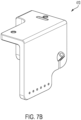
- An additional drilling guide (410) that can be attached to the combination drill guide/insertion handle (200) may be used to similarly, and precisely, drill openings in the bone for transfixion screws that are obliquely or transversally oriented on the intramedullary nail, in alignment with transfixion screw holes (111). Examples of such a guide are shown in FIGS 7A and 7B , and the final result is shown in FIGS 8A , 8B , and 8C .
- the combination drill guide/insertion handle (200) may be manufactured as a single component or may be modular to separate the drill guide portion from the insertion handle. If the device is manufactured as two separate components, the drill guide and insertion handle can be locked to, and unlocked from, each other through a variety of means, including an optional top connecting screw (207).
- locking screw (300) which locks intramedullary nail (100) with combination drill guide/insertion handle (200) as shown in FIGS. 5 and 6 .
- Connecting screw (300) comprises an elongated shaft (301) extending from a knob (302) to connecting screw tip (303).
- Knob (302) may optionally be knurled to ease turning same with fingers.
- connecting screw can be further tightened by a driver instrument (not shown).
- Locking screw tip (303) comprises an external thread that is adapted to mate with the internal thread internal thread (105) of the trailing end (104) of intramedullary nail (100) and also optionally with the internal thread (109) of the leading end (103) of intramedullary nail (100).
- FIGS. 5 and 6 shown are assembled and exploded views of the complete intramedullary nail system assembly (1) which further illustrate how the intramedullary nail (100), combination drill guide/insertion handle (200) and connecting screw (300) are designed to mate.
- top connecting screw (207) is optional and not needed in embodiments where the combination drill guide/insertion handle (200) where the same is of unitary construction.
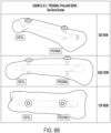
- FIGS. 8A , 8B , and 8C illustrate examples of embodiments of an intramedullary nail implanted on metacarpal and phalanx bones using different types of screws.
- An exemplary procedure for insertion of the disclosed intramedullary nail generally consists of the following steps (the dimensions referenced here are for a 4.0 mm diameter nail and should not be considered limiting for differently sized nails):
Landscapes
- Health & Medical Sciences (AREA)
- Orthopedic Medicine & Surgery (AREA)
- Surgery (AREA)
- Life Sciences & Earth Sciences (AREA)
- Biomedical Technology (AREA)
- Public Health (AREA)
- Veterinary Medicine (AREA)
- Engineering & Computer Science (AREA)
- Nuclear Medicine, Radiotherapy & Molecular Imaging (AREA)
- Heart & Thoracic Surgery (AREA)
- Medical Informatics (AREA)
- Molecular Biology (AREA)
- Animal Behavior & Ethology (AREA)
- General Health & Medical Sciences (AREA)
- Neurology (AREA)
- Dentistry (AREA)
- Oral & Maxillofacial Surgery (AREA)
- Surgical Instruments (AREA)
Description
- The invention relates generally to bone fusion devices and systems, and, in particular, to an intramedullary bone fixation nail adapted to interface with Kirschner wires or pins ("K-wires") for easier, more accurate, and more efficient placement of the bone fixation nail at the desired location.
- Intramedullary fixation nails are known in the art. It is known to implant unthreaded rods or nails within the medullar region of a fractured bone, or of reduced fragments of a broken bone, in order to stabilize the bone while it heals. The common procedure for implanting such a device is to form an opening on one end of the fractured or broken bone, the opening extending into the medulla and through the fracture or break. This initial opening is commonly formed by using a K-wire which is a smooth steel pin that is inserted into the bone as a guide for insertion of the nail. The fracture or break is then reduced. A cannulated drill, using the K-wire as a guide, is then used to expand the opening made using the K-wire to a width suitable for insertion of the nail. The K-wire is then pushed out simultaneously as the nail is then inserted into the bone.
- One shortcoming of known intramedullary nails is that problems often arise during insertion of the nail because once the K-wire is removed, and before the nail is inserted, debris, tissue and fluid may become trapped inside the opening formed in the bone. In fact, debris, tissue, and fluid may completely obscure or cover up the opening and make it difficult, if not impossible, to insert the nail without further clearing.
- Further, any debris, tissue or fluid that is trapped inside the bone may interfere with the functioning of the nail, inhibit bone growth, create a risk for infection, and prevent the precise determination of whether the nail has been placed in the correct position.
- Prior art document
US 2008/221574 A1 discloses an intramedullary nail for clavicle fracture fixation. Both ends of the nail are tapered and include a threaded bore to which a threaded K-wire can be removably attached.US 2014/188113 A1 relates to a surgical nail for treating a fractured bone. The nail includes a nail body extending along a longitudinal axis from a trailing end to a leading end and a trailing end locking aperture extending transversely through a trailing end portion thereof and a leading end locking aperture extending transversely through a leading end portion thereof.US 6 080159 A relates to an interlocking intramedullary nail system copmrising a nail having an upper extremity, a lower extremity and transverse locking ducts in the upper and lower extremity and a plurality of fixation bone screws adapted to be received by the locking ducts. - The invention relates to an intramedullary nail comprising the features of claim 1. Preferred embodiments of the invention are defined in the dependent claims.
- It is an object of the instant invention to provide an intramedullary bone fixation nail that is adapted to cooperate with a K-wire to easily and efficiently insert the nail into a fractured or broken bone while significantly reducing the possibility of debris, tissue, and/or fluid being trapped in the opening made in the bone to accommodate the nail. In operation, the nail disclosed herein pushes out the K-wire from the medullary canal while the nail is simultaneously inserted.
- The disclosed intramedullary nail comprises a shaft having a length, a constant diameter, and an exterior bone contacting surface. The nail further comprises a leading (or distal) end and a trailing (or proximal) end. The leading end is progressively tapered for ease of insertion, being atraumatic in design and comprises a well or cup, adapted to receive the tip of a standard K-wire. The well or cup of the leading end may optionally include internal threads adapted to mate with a removal tool. The trailing end comprises a driving fitting adapted for attachment to a driving tool for insertion of the nail into the prepared bone. The trailing end may optionally include an internal thread that can be used to secure the nail to a drill guide which can also function as an insertion handle. The nail's shaft may also optionally be equipped with threaded and/or unthreaded cross-drilled holes for insertion of locking compression screws and transfixion screws, respectively, once the nail is placed as desired.
- The invention is represented only in
fig. 2 , the remaining figures do not show the claimed intramedullary nail but are useful for understanding the invention. -
FIGS. 1A-1B are rear isometric, and front isometric views, respectively, of an intramedullary nail -
FIG. 2 is an isometric view of an embodiment of the intramedullary nail of the present invention having a flared trailing end. -
FIGS. 3A-3B are rear isometric views of an embodiment of the combination drill guide/insertion handle and a detailed view of nail implant attachment to drill guide/insertion handle. -
FIG. 4 illustrates the locking screw used to attach the intramedullary nail to the combination drill guide/insertion handle -
FIG. 5 illustrates an assembled view of an intramedullary nail, combination drill guide/insertion handle, and locking screw -
FIG. 6 illustrates an exploded view of an intramedullary nail, combination drill guide/insertion handle, and locking screw. -
FIGS. 7A and7B illustrate guides used to assist in drilling bone holes matching oblique or transversal cross-drilled screw holes on the intramedullary nail -
FIGS. 8A ,8B , and8C are illustrations of embodiments of the intramedullary nail implanted on metacarpal and phalanx bones using different types of screws. - Referring now to
FIGS. 1A-1B , therein are shown several views of an intramedullary nail (100) The intramedullary nail (100) comprises an elongated shaft (101) having an exterior bone contacting surface (102), a leading (or distal) end (103), a trailing (or proximal) end (104). - The trailing end (104) comprises an internal thread (105) and an anti-rotational feature (106) adapted to mate with a corresponding feature (204) on the combination drill guide/insertion handle (200) (See
FIG. 3A-3B ). The internal thread is adapted to mate with the corresponding threaded tip (303) of the locking screw (300) (SeeFIG. 4 ). - The leading end (103) comprises a well or cup (107) which is adapted to accept a K-Wire tip upon insertion into the bone. The leading end may also include internal thread (109) adapted to mate with a removal tool (not shown) that may be utilized to pull, rather than push, the intramedullary nail (100) out of the bone, once inserted, if needed. Locking screw (300) (See
FIG. 4 ) may optionally serve as a removal tool. The leading end (103) includes a tapered tip (108) to ease insertion of the nail into the bone (SeeFIGS. 1A ,1B ). - The elongated shaft (101) may also include threaded or unthreaded cross-drilled holes (110,111) for insertion of locking screws (not shown).
- In an alternative embodiment of the intramedullary nail (150), shown in
FIG. 2 and according to the claimed invention, the trailing end (151) includes a flared section (152) to provide additional strength, and to ensure proper mating with the mating feature (204) of combination drill guide/insertion handle (200) (SeeFIG. 3B ) in the case of intramedullary nails of smaller diameters. - Referring next to
FIG. 3A , therein are shown several views of a combination drill guide/insertion handle (200). The combination drill guide/insertion handle (200) is generally L-shaped comprising a vertical handle portion (201) and a horizontal drill guide portion (202). The vertical handle portion (201) and drill guide portion (202) may be of unitary construction or may comprise two or more components that are assembled together to form the combination drill guide/insertion handle. At the bottom of the vertical handle portion (202) is a horizontal mandrel (203) which can optionally taper partially or completely towards its tip (204). Tip (204) of mandrel (203) is adapted to mate with anti-rotational feature (106) of intramedullary nail (100) (SeeFIG 1A ). - Combination drill guide/insertion handle (200) additionally comprises an orifice (205) extending from the rear of the vertical handle (201), through the mandrel (203), and through the tip (204) of the mandrel (203). Orifice (205) is adapted to accept locking screw (300) (See
FIG. 4 ) in order to secure the intramedullary nail (100) to the combination drill guide/insertion handle (200). - Combination drill guide/insertion handle (200) also comprises one or more drill slots (206). When intramedullary nail (100) is attached to mandrel tip (204), with locking screw (300), one or more of the drill slots on the drill guide/insertion handle are aligned with one or more corresponding locking compression screw holes (110,
FIG 1A ) of the intramedullary nail. The drill slots are thus used to precisely drill openings in the bone for locking compression screws which mate with the threaded vertical holes (110) (SeeFIGS. 1A ,1B , and8 ). An additional drilling guide (410) that can be attached to the combination drill guide/insertion handle (200) may be used to similarly, and precisely, drill openings in the bone for transfixion screws that are obliquely or transversally oriented on the intramedullary nail, in alignment with transfixion screw holes (111). Examples of such a guide are shown inFIGS 7A and7B , and the final result is shown inFIGS 8A ,8B , and8C . - The combination drill guide/insertion handle (200) may be manufactured as a single component or may be modular to separate the drill guide portion from the insertion handle. If the device is manufactured as two separate components, the drill guide and insertion handle can be locked to, and unlocked from, each other through a variety of means, including an optional top connecting screw (207).
- Referring next to
FIG. 4 , shown is locking screw (300) which locks intramedullary nail (100) with combination drill guide/insertion handle (200) as shown inFIGS. 5 and6 . - Connecting screw (300) comprises an elongated shaft (301) extending from a knob (302) to connecting screw tip (303). Knob (302) may optionally be knurled to ease turning same with fingers. Alternatively, instead of knob (302), connecting screw can be further tightened by a driver instrument (not shown). Locking screw tip (303) comprises an external thread that is adapted to mate with the internal thread internal thread (105) of the trailing end (104) of intramedullary nail (100) and also optionally with the internal thread (109) of the leading end (103) of intramedullary nail (100).
- Referring next to
FIGS. 5 and6 , shown are assembled and exploded views of the complete intramedullary nail system assembly (1) which further illustrate how the intramedullary nail (100), combination drill guide/insertion handle (200) and connecting screw (300) are designed to mate. As previously noted, top connecting screw (207) is optional and not needed in embodiments where the combination drill guide/insertion handle (200) where the same is of unitary construction. -
FIGS. 8A ,8B , and8C illustrate examples of embodiments of an intramedullary nail implanted on metacarpal and phalanx bones using different types of screws. - An exemplary procedure for insertion of the disclosed intramedullary nail generally consists of the following steps (the dimensions referenced here are for a 4.0 mm diameter nail and should not be considered limiting for differently sized nails):
- (1) An 8-inch long, 1.6mm K-Wire is inserted through the intramedullary canal of the bone to be treated while aligning distal and proximal fragments of the fracture. This centralizes the location of the nail within the canal of the bone. Both ends of the K-Wire should extend past the length of the bone and soft tissue.
- (2) With the K-Wire remaining in place, begin reaming over the 1.6mm K-Wire with a cannulated awl first to just past the cortical bone of the base of the bone. Then ream with a 2.7mm cannulated reamer from proximal to distal up to the intended location of the distal end of the nail implant.
- (3) After reaming with the 2.7mm cannulated reamer, continue reaming with the next sequential reamer, 3.3mm up to the same location as reamed by the 2.7mm reamer. If 3.3mm reamer size is felt sufficient, then a 3.0mm Nail is chosen. However, if a 3.3mm reamer is not felt as sufficient for the medullary canal of the bone, then subsequently ream with a 3.8mm and a 4.3mm cannulated reamer for either a 3.5mm Nail or a 4.0mm Nail, respectively.
- (4) Attach the nail to the combination drill guide/insertion handle by using a locking screw that mates with a thread at the proximal end of the nail.
- (5) Mate the well or cup in the distal end of the nail with the tip of the K-Wire which remains inserted within the medullary canal of the bone. As the nail is inserted, it will push the 1.6mm K-Wire out while simultaneously taking its place within the bone.
- (6) Once nail is inserted to its final place within the bone, drill a vertical hole into the bone through the nail's locking compression screw hole using a 1.4mm K-Wire by using the marked drilling guide locations (not shown) (distal - based on nail length and proximal) engraved on the combination drilling guide/insertion handle. The 1.4mm K-Wire should penetrate the bone from the near cortex and extend through one of the vertical holes on the nail's shaft up to the far cortex of the bone.
- (7) Insert an appropriately sized locking compression screw into the drilled cross-hole and tighten to lock the nail into position.
- (8) Optionally, cross-holes, oriented at 45° and 90° can be drilled and, additional screws can be inserted, using other marked drilling guide adapter locations (not shown).
- Although described above in connection with certain bone shapes, nail diameters, and screw types these descriptions are not intended to be limiting as various modifications may be made therein without departing from the scope of the invention as defined by the claims.
Claims (9)
- An intramedullary nail (100) comprising:a shaft (101) having first and second opposing ends, a length, a constant diameter, and an exterior bone contacting surface (102);a leading end (103) adjacent to the first opposing end, the leading end (103) progressively tapering from said constant diameter at the first opposing end and terminating in a cup (107), the cup (107) adapted to receive a tip of a k-wire inserted in a bone, and push out the k-wire upon insertion of the intramedullary nail (100) into the bone;a trailing end (104) adjacent to the second opposing end, the trailing end (104) comprising a flared section (152) and terminating in a fitting adapted for attachment to a driving tool;wherein the shaft (101), the leading end (103), and the trailing end (104) are adapted for insertion into the medulla of the bone.
- The intramedullary nail (100) of claim 1 wherein the cup (107) of the leading end (103) further comprises internal threads (109).
- The intramedullary nail (100) of claim 2 wherein the internal threads (109) of the cup (107) of the leading end (103) are adapted to mate with an externally threaded removal tool.
- The intramedullary nail (100) of claim 1 wherein the trailing end (104) further comprises internal threads (105).
- The intramedullary nail (100) of claim 4 wherein the internal threads (105) of the trailing end (104) are adapted to mate with an externally threaded insertion handle.
- The intramedullary nail (100) of claim 1 wherein the shaft (101) further comprises one or more cross drilled holes (110, 111).
- The intramedullary nail (100) of claim 6 wherein at least one of the one or more cross drilled holes (110, 111) is at least partially threaded.
- The intramedullary nail (100) of claim 6 wherein at least one of the one or more cross drilled holes (110, 111) is unthreaded.
- The intermedullary nail (100) of claim 4 wherein the trailing end (104) fitting comprises an anti-rotational feature (106).
Applications Claiming Priority (2)
| Application Number | Priority Date | Filing Date | Title |
|---|---|---|---|
| US201962926156P | 2019-10-25 | 2019-10-25 | |
| PCT/US2020/056799 WO2021081168A1 (en) | 2019-10-25 | 2020-10-22 | Intramedullary fixation nail and method of use |
Publications (3)
| Publication Number | Publication Date |
|---|---|
| EP4048170A1 EP4048170A1 (en) | 2022-08-31 |
| EP4048170A4 EP4048170A4 (en) | 2023-11-29 |
| EP4048170B1 true EP4048170B1 (en) | 2025-04-23 |
Family
ID=75585309
Family Applications (1)
| Application Number | Title | Priority Date | Filing Date |
|---|---|---|---|
| EP20878700.2A Active EP4048170B1 (en) | 2019-10-25 | 2020-10-22 | Intramedullary fixation nail |
Country Status (7)
| Country | Link |
|---|---|
| US (2) | US11344341B2 (en) |
| EP (1) | EP4048170B1 (en) |
| JP (2) | JP7581344B2 (en) |
| AU (1) | AU2020370260B2 (en) |
| CA (1) | CA3157341C (en) |
| ES (1) | ES3030866T3 (en) |
| WO (1) | WO2021081168A1 (en) |
Families Citing this family (4)
| Publication number | Priority date | Publication date | Assignee | Title |
|---|---|---|---|---|
| EP4087505A4 (en) | 2020-04-09 | 2024-05-15 | Wright Medical Technology, Inc. | Jigs, systems, and methods for correcting joint deformities |
| USD935613S1 (en) * | 2020-05-29 | 2021-11-09 | Brent Austin McNeely | Intramedullary cement spacer mold system |
| US20230031466A1 (en) * | 2021-07-29 | 2023-02-02 | Trimed, Incorporated | Bone implant and method of controlling the bone implant |
| US12349947B2 (en) * | 2021-10-14 | 2025-07-08 | Western Washington University | Distal-screw guiding system for interlocking intramedullary nail implants |
Family Cites Families (11)
| Publication number | Priority date | Publication date | Assignee | Title |
|---|---|---|---|---|
| IL48826A (en) * | 1976-01-13 | 1978-08-31 | Aginsky Yacov | Intramedullary compression nail for the treatment of bone fractures |
| US4875474A (en) | 1988-01-29 | 1989-10-24 | Biomet, Inc. | Variable wall thickness interlocking intramedullary nail |
| DE9109883U1 (en) * | 1991-08-09 | 1991-09-26 | Howmedica GmbH, 2314 Schönkirchen | Locking nail for the treatment of femoral fractures in the middle and trochanteric region |
| US6080159A (en) * | 1996-07-16 | 2000-06-27 | Sulzer Orthopedics Ltd. | Ascending centromedullary thigh bone pin with mechanical clamping of its two ends |
| US6648889B2 (en) * | 2001-04-24 | 2003-11-18 | Dale G. Bramlet | Intramedullary hip nail with bifurcated lock |
| DE502004008054D1 (en) | 2004-06-24 | 2008-10-23 | Synthes Gmbh | MARK NAGEL |
| US7722611B2 (en) | 2007-03-05 | 2010-05-25 | Depuy Products, Inc. | Method of treating a clavicle fracture |
| KR101926339B1 (en) | 2010-09-09 | 2019-03-07 | 신세스 게엠바하 | Surgical nail |
| JP5913376B2 (en) * | 2011-02-08 | 2016-04-27 | ストライカー トラウマ ゲーエムベーハー | Implant system for bone fixation |
| US10123827B2 (en) | 2013-09-06 | 2018-11-13 | Cristobal ROBLEDO | Distal locking intramedullary nail |
| US10695109B2 (en) * | 2017-12-13 | 2020-06-30 | DePuy Synthes Products, Inc. | Intramedullary nail with cannulation access hole |
-
2020
- 2020-10-21 US US17/076,661 patent/US11344341B2/en active Active
- 2020-10-22 CA CA3157341A patent/CA3157341C/en active Active
- 2020-10-22 EP EP20878700.2A patent/EP4048170B1/en active Active
- 2020-10-22 ES ES20878700T patent/ES3030866T3/en active Active
- 2020-10-22 AU AU2020370260A patent/AU2020370260B2/en active Active
- 2020-10-22 JP JP2022522971A patent/JP7581344B2/en active Active
- 2020-10-22 WO PCT/US2020/056799 patent/WO2021081168A1/en not_active Ceased
-
2022
- 2022-05-27 US US17/804,433 patent/US12102359B2/en active Active
-
2024
- 2024-10-30 JP JP2024190600A patent/JP2025003736A/en active Pending
Also Published As
| Publication number | Publication date |
|---|---|
| US12102359B2 (en) | 2024-10-01 |
| JP2022553003A (en) | 2022-12-21 |
| JP2025003736A (en) | 2025-01-09 |
| AU2020370260B2 (en) | 2024-11-14 |
| ES3030866T3 (en) | 2025-07-02 |
| CA3157341A1 (en) | 2021-04-29 |
| US20220287743A1 (en) | 2022-09-15 |
| AU2020370260A1 (en) | 2022-04-21 |
| JP7581344B2 (en) | 2024-11-12 |
| CA3157341C (en) | 2024-01-30 |
| US11344341B2 (en) | 2022-05-31 |
| WO2021081168A1 (en) | 2021-04-29 |
| US20210121209A1 (en) | 2021-04-29 |
| EP4048170A4 (en) | 2023-11-29 |
| EP4048170A1 (en) | 2022-08-31 |
Similar Documents
| Publication | Publication Date | Title |
|---|---|---|
| US12102359B2 (en) | Intramedullary fixation nail and method of use | |
| EP2613720B1 (en) | Surgical nail | |
| US6926720B2 (en) | Jig assembly for implantation of a fracture fixation device | |
| EP1124492B1 (en) | Fracture treatment | |
| US7299561B2 (en) | Gauge system for use in implantation of a fracture fixation device | |
| US8353910B2 (en) | Hip helical implant | |
| EP1713410B1 (en) | Proximal humeral fracture fixation system comprising a plate including a post rotationally locked in a post hole, and a rigid cross support | |
| US7722611B2 (en) | Method of treating a clavicle fracture | |
| US7232442B2 (en) | Humeral nail | |
| US3977398A (en) | Fluted sub-trochanteric nail system | |
| GB2209947A (en) | Device for fixing femur fractures | |
| KR20030062532A (en) | Intramedullary nail, device for inserting a screw into the same and method thereof | |
| US8632551B2 (en) | Resetting tool | |
| KR101702097B1 (en) | Reamer and drill guiding device | |
| US20250114209A1 (en) | System and method for minimally-invasive bone fusion | |
| US12232749B2 (en) | Drill guide for orthopedic device |
Legal Events
| Date | Code | Title | Description |
|---|---|---|---|
| STAA | Information on the status of an ep patent application or granted ep patent |
Free format text: STATUS: THE INTERNATIONAL PUBLICATION HAS BEEN MADE |
|
| PUAI | Public reference made under article 153(3) epc to a published international application that has entered the european phase |
Free format text: ORIGINAL CODE: 0009012 |
|
| STAA | Information on the status of an ep patent application or granted ep patent |
Free format text: STATUS: REQUEST FOR EXAMINATION WAS MADE |
|
| 17P | Request for examination filed |
Effective date: 20220330 |
|
| AK | Designated contracting states |
Kind code of ref document: A1 Designated state(s): AL AT BE BG CH CY CZ DE DK EE ES FI FR GB GR HR HU IE IS IT LI LT LU LV MC MK MT NL NO PL PT RO RS SE SI SK SM TR |
|
| DAV | Request for validation of the european patent (deleted) | ||
| DAX | Request for extension of the european patent (deleted) | ||
| REG | Reference to a national code |
Ref legal event code: R079 Ipc: A61B0017720000 Ref country code: DE Ref legal event code: R079 Ref document number: 602020050153 Country of ref document: DE Free format text: PREVIOUS MAIN CLASS: A61B0017160000 Ipc: A61B0017720000 |
|
| A4 | Supplementary search report drawn up and despatched |
Effective date: 20231027 |
|
| RIC1 | Information provided on ipc code assigned before grant |
Ipc: A61B 17/17 20060101ALN20231023BHEP Ipc: A61B 17/72 20060101AFI20231023BHEP |
|
| STAA | Information on the status of an ep patent application or granted ep patent |
Free format text: STATUS: EXAMINATION IS IN PROGRESS |
|
| 17Q | First examination report despatched |
Effective date: 20240606 |
|
| GRAP | Despatch of communication of intention to grant a patent |
Free format text: ORIGINAL CODE: EPIDOSNIGR1 |
|
| STAA | Information on the status of an ep patent application or granted ep patent |
Free format text: STATUS: GRANT OF PATENT IS INTENDED |
|
| RIC1 | Information provided on ipc code assigned before grant |
Ipc: A61B 17/17 20060101ALI20241217BHEP Ipc: A61B 17/72 20060101AFI20241217BHEP |
|
| INTG | Intention to grant announced |
Effective date: 20250107 |
|
| GRAJ | Information related to disapproval of communication of intention to grant by the applicant or resumption of examination proceedings by the epo deleted |
Free format text: ORIGINAL CODE: EPIDOSDIGR1 |
|
| STAA | Information on the status of an ep patent application or granted ep patent |
Free format text: STATUS: EXAMINATION IS IN PROGRESS |
|
| GRAP | Despatch of communication of intention to grant a patent |
Free format text: ORIGINAL CODE: EPIDOSNIGR1 |
|
| STAA | Information on the status of an ep patent application or granted ep patent |
Free format text: STATUS: GRANT OF PATENT IS INTENDED |
|
| GRAS | Grant fee paid |
Free format text: ORIGINAL CODE: EPIDOSNIGR3 |
|
| INTC | Intention to grant announced (deleted) | ||
| P01 | Opt-out of the competence of the unified patent court (upc) registered |
Free format text: CASE NUMBER: APP_7097/2025 Effective date: 20250211 |
|
| GRAA | (expected) grant |
Free format text: ORIGINAL CODE: 0009210 |
|
| STAA | Information on the status of an ep patent application or granted ep patent |
Free format text: STATUS: THE PATENT HAS BEEN GRANTED |
|
| INTG | Intention to grant announced |
Effective date: 20250219 |
|
| AK | Designated contracting states |
Kind code of ref document: B1 Designated state(s): AL AT BE BG CH CY CZ DE DK EE ES FI FR GB GR HR HU IE IS IT LI LT LU LV MC MK MT NL NO PL PT RO RS SE SI SK SM TR |
|
| REG | Reference to a national code |
Ref country code: GB Ref legal event code: FG4D |
|
| REG | Reference to a national code |
Ref country code: CH Ref legal event code: EP |
|
| REG | Reference to a national code |
Ref country code: DE Ref legal event code: R096 Ref document number: 602020050153 Country of ref document: DE |
|
| REG | Reference to a national code |
Ref country code: IE Ref legal event code: FG4D |
|
| REG | Reference to a national code |
Ref country code: ES Ref legal event code: FG2A Ref document number: 3030866 Country of ref document: ES Kind code of ref document: T3 Effective date: 20250702 |
|
| REG | Reference to a national code |
Ref country code: NL Ref legal event code: MP Effective date: 20250423 |
|
| PG25 | Lapsed in a contracting state [announced via postgrant information from national office to epo] |
Ref country code: NL Free format text: LAPSE BECAUSE OF FAILURE TO SUBMIT A TRANSLATION OF THE DESCRIPTION OR TO PAY THE FEE WITHIN THE PRESCRIBED TIME-LIMIT Effective date: 20250423 |
|
| REG | Reference to a national code |
Ref country code: AT Ref legal event code: MK05 Ref document number: 1787027 Country of ref document: AT Kind code of ref document: T Effective date: 20250423 |
|
| PG25 | Lapsed in a contracting state [announced via postgrant information from national office to epo] |
Ref country code: FI Free format text: LAPSE BECAUSE OF FAILURE TO SUBMIT A TRANSLATION OF THE DESCRIPTION OR TO PAY THE FEE WITHIN THE PRESCRIBED TIME-LIMIT Effective date: 20250423 Ref country code: PT Free format text: LAPSE BECAUSE OF FAILURE TO SUBMIT A TRANSLATION OF THE DESCRIPTION OR TO PAY THE FEE WITHIN THE PRESCRIBED TIME-LIMIT Effective date: 20250825 |
|
| REG | Reference to a national code |
Ref country code: LT Ref legal event code: MG9D |
|
| PG25 | Lapsed in a contracting state [announced via postgrant information from national office to epo] |
Ref country code: NO Free format text: LAPSE BECAUSE OF FAILURE TO SUBMIT A TRANSLATION OF THE DESCRIPTION OR TO PAY THE FEE WITHIN THE PRESCRIBED TIME-LIMIT Effective date: 20250723 Ref country code: GR Free format text: LAPSE BECAUSE OF FAILURE TO SUBMIT A TRANSLATION OF THE DESCRIPTION OR TO PAY THE FEE WITHIN THE PRESCRIBED TIME-LIMIT Effective date: 20250724 |
|
| PG25 | Lapsed in a contracting state [announced via postgrant information from national office to epo] |
Ref country code: PL Free format text: LAPSE BECAUSE OF FAILURE TO SUBMIT A TRANSLATION OF THE DESCRIPTION OR TO PAY THE FEE WITHIN THE PRESCRIBED TIME-LIMIT Effective date: 20250423 |
|
| PG25 | Lapsed in a contracting state [announced via postgrant information from national office to epo] |
Ref country code: BG Free format text: LAPSE BECAUSE OF FAILURE TO SUBMIT A TRANSLATION OF THE DESCRIPTION OR TO PAY THE FEE WITHIN THE PRESCRIBED TIME-LIMIT Effective date: 20250423 |
|
| PG25 | Lapsed in a contracting state [announced via postgrant information from national office to epo] |
Ref country code: HR Free format text: LAPSE BECAUSE OF FAILURE TO SUBMIT A TRANSLATION OF THE DESCRIPTION OR TO PAY THE FEE WITHIN THE PRESCRIBED TIME-LIMIT Effective date: 20250423 |
|
| PG25 | Lapsed in a contracting state [announced via postgrant information from national office to epo] |
Ref country code: AT Free format text: LAPSE BECAUSE OF FAILURE TO SUBMIT A TRANSLATION OF THE DESCRIPTION OR TO PAY THE FEE WITHIN THE PRESCRIBED TIME-LIMIT Effective date: 20250423 |
|
| PG25 | Lapsed in a contracting state [announced via postgrant information from national office to epo] |
Ref country code: RS Free format text: LAPSE BECAUSE OF FAILURE TO SUBMIT A TRANSLATION OF THE DESCRIPTION OR TO PAY THE FEE WITHIN THE PRESCRIBED TIME-LIMIT Effective date: 20250723 |
|
| PG25 | Lapsed in a contracting state [announced via postgrant information from national office to epo] |
Ref country code: IS Free format text: LAPSE BECAUSE OF FAILURE TO SUBMIT A TRANSLATION OF THE DESCRIPTION OR TO PAY THE FEE WITHIN THE PRESCRIBED TIME-LIMIT Effective date: 20250823 |
|
| PG25 | Lapsed in a contracting state [announced via postgrant information from national office to epo] |
Ref country code: LV Free format text: LAPSE BECAUSE OF FAILURE TO SUBMIT A TRANSLATION OF THE DESCRIPTION OR TO PAY THE FEE WITHIN THE PRESCRIBED TIME-LIMIT Effective date: 20250423 |
|
| REG | Reference to a national code |
Ref country code: CH Ref legal event code: U11 Free format text: ST27 STATUS EVENT CODE: U-0-0-U10-U11 (AS PROVIDED BY THE NATIONAL OFFICE) Effective date: 20251101 |
|
| PGFP | Annual fee paid to national office [announced via postgrant information from national office to epo] |
Ref country code: LU Payment date: 20251027 Year of fee payment: 6 |
|
| PGFP | Annual fee paid to national office [announced via postgrant information from national office to epo] |
Ref country code: DE Payment date: 20251029 Year of fee payment: 6 |
|
| PGFP | Annual fee paid to national office [announced via postgrant information from national office to epo] |
Ref country code: GB Payment date: 20251027 Year of fee payment: 6 |
|
| PGFP | Annual fee paid to national office [announced via postgrant information from national office to epo] |
Ref country code: MC Payment date: 20251003 Year of fee payment: 6 |
|
| PG25 | Lapsed in a contracting state [announced via postgrant information from national office to epo] |
Ref country code: SM Free format text: LAPSE BECAUSE OF FAILURE TO SUBMIT A TRANSLATION OF THE DESCRIPTION OR TO PAY THE FEE WITHIN THE PRESCRIBED TIME-LIMIT Effective date: 20250423 Ref country code: DK Free format text: LAPSE BECAUSE OF FAILURE TO SUBMIT A TRANSLATION OF THE DESCRIPTION OR TO PAY THE FEE WITHIN THE PRESCRIBED TIME-LIMIT Effective date: 20250423 |
|
| PGFP | Annual fee paid to national office [announced via postgrant information from national office to epo] |
Ref country code: FR Payment date: 20251027 Year of fee payment: 6 |
|
| PGFP | Annual fee paid to national office [announced via postgrant information from national office to epo] |
Ref country code: CH Payment date: 20251101 Year of fee payment: 6 |
|
| PG25 | Lapsed in a contracting state [announced via postgrant information from national office to epo] |
Ref country code: CZ Free format text: LAPSE BECAUSE OF FAILURE TO SUBMIT A TRANSLATION OF THE DESCRIPTION OR TO PAY THE FEE WITHIN THE PRESCRIBED TIME-LIMIT Effective date: 20250423 |
|
| PGFP | Annual fee paid to national office [announced via postgrant information from national office to epo] |
Ref country code: IE Payment date: 20251027 Year of fee payment: 6 |
|
| PG25 | Lapsed in a contracting state [announced via postgrant information from national office to epo] |
Ref country code: EE Free format text: LAPSE BECAUSE OF FAILURE TO SUBMIT A TRANSLATION OF THE DESCRIPTION OR TO PAY THE FEE WITHIN THE PRESCRIBED TIME-LIMIT Effective date: 20250423 |
|
| REG | Reference to a national code |
Ref country code: DE Ref legal event code: R097 Ref document number: 602020050153 Country of ref document: DE |
|
| PG25 | Lapsed in a contracting state [announced via postgrant information from national office to epo] |
Ref country code: SK Free format text: LAPSE BECAUSE OF FAILURE TO SUBMIT A TRANSLATION OF THE DESCRIPTION OR TO PAY THE FEE WITHIN THE PRESCRIBED TIME-LIMIT Effective date: 20250423 |
|
| PG25 | Lapsed in a contracting state [announced via postgrant information from national office to epo] |
Ref country code: IT Free format text: LAPSE BECAUSE OF FAILURE TO SUBMIT A TRANSLATION OF THE DESCRIPTION OR TO PAY THE FEE WITHIN THE PRESCRIBED TIME-LIMIT Effective date: 20250423 |
|
| PGFP | Annual fee paid to national office [announced via postgrant information from national office to epo] |
Ref country code: ES Payment date: 20251103 Year of fee payment: 6 |
|
| PG25 | Lapsed in a contracting state [announced via postgrant information from national office to epo] |
Ref country code: RO Free format text: LAPSE BECAUSE OF FAILURE TO SUBMIT A TRANSLATION OF THE DESCRIPTION OR TO PAY THE FEE WITHIN THE PRESCRIBED TIME-LIMIT Effective date: 20250423 |
|
| PLBE | No opposition filed within time limit |
Free format text: ORIGINAL CODE: 0009261 |
|
| STAA | Information on the status of an ep patent application or granted ep patent |
Free format text: STATUS: NO OPPOSITION FILED WITHIN TIME LIMIT |
|
| REG | Reference to a national code |
Ref country code: CH Ref legal event code: L10 Free format text: ST27 STATUS EVENT CODE: U-0-0-L10-L00 (AS PROVIDED BY THE NATIONAL OFFICE) Effective date: 20260304 |
|
| 26N | No opposition filed |
Effective date: 20260126 |