EP4047984A1 - Methods and devices for reducing temperature for base station and user equipment - Google Patents
Methods and devices for reducing temperature for base station and user equipment Download PDFInfo
- Publication number
- EP4047984A1 EP4047984A1 EP22167650.5A EP22167650A EP4047984A1 EP 4047984 A1 EP4047984 A1 EP 4047984A1 EP 22167650 A EP22167650 A EP 22167650A EP 4047984 A1 EP4047984 A1 EP 4047984A1
- Authority
- EP
- European Patent Office
- Prior art keywords
- base station
- configuration information
- target
- handover request
- source base
- Prior art date
- Legal status (The legal status is an assumption and is not a legal conclusion. Google has not performed a legal analysis and makes no representation as to the accuracy of the status listed.)
- Ceased
Links
Images



Classifications
-
- H—ELECTRICITY
- H04—ELECTRIC COMMUNICATION TECHNIQUE
- H04L—TRANSMISSION OF DIGITAL INFORMATION, e.g. TELEGRAPHIC COMMUNICATION
- H04L41/00—Arrangements for maintenance, administration or management of data switching networks, e.g. of packet switching networks
- H04L41/08—Configuration management of networks or network elements
- H04L41/0803—Configuration setting
- H04L41/0823—Configuration setting characterised by the purposes of a change of settings, e.g. optimising configuration for enhancing reliability
-
- H—ELECTRICITY
- H04—ELECTRIC COMMUNICATION TECHNIQUE
- H04L—TRANSMISSION OF DIGITAL INFORMATION, e.g. TELEGRAPHIC COMMUNICATION
- H04L41/00—Arrangements for maintenance, administration or management of data switching networks, e.g. of packet switching networks
- H04L41/08—Configuration management of networks or network elements
- H04L41/0803—Configuration setting
- H04L41/0813—Configuration setting characterised by the conditions triggering a change of settings
- H04L41/082—Configuration setting characterised by the conditions triggering a change of settings the condition being updates or upgrades of network functionality
-
- G—PHYSICS
- G06—COMPUTING OR CALCULATING; COUNTING
- G06F—ELECTRIC DIGITAL DATA PROCESSING
- G06F1/00—Details not covered by groups G06F3/00 - G06F13/00 and G06F21/00
- G06F1/16—Constructional details or arrangements
- G06F1/20—Cooling means
- G06F1/203—Cooling means for portable computers, e.g. for laptops
-
- G—PHYSICS
- G06—COMPUTING OR CALCULATING; COUNTING
- G06F—ELECTRIC DIGITAL DATA PROCESSING
- G06F1/00—Details not covered by groups G06F3/00 - G06F13/00 and G06F21/00
- G06F1/16—Constructional details or arrangements
- G06F1/20—Cooling means
- G06F1/206—Cooling means comprising thermal management
-
- G—PHYSICS
- G06—COMPUTING OR CALCULATING; COUNTING
- G06F—ELECTRIC DIGITAL DATA PROCESSING
- G06F1/00—Details not covered by groups G06F3/00 - G06F13/00 and G06F21/00
- G06F1/26—Power supply means, e.g. regulation thereof
- G06F1/32—Means for saving power
- G06F1/3203—Power management, i.e. event-based initiation of a power-saving mode
- G06F1/3206—Monitoring of events, devices or parameters that trigger a change in power modality
-
- H—ELECTRICITY
- H04—ELECTRIC COMMUNICATION TECHNIQUE
- H04W—WIRELESS COMMUNICATION NETWORKS
- H04W28/00—Network traffic management; Network resource management
- H04W28/16—Central resource management; Negotiation of resources or communication parameters, e.g. negotiating bandwidth or QoS [Quality of Service]
- H04W28/18—Negotiating wireless communication parameters
-
- H—ELECTRICITY
- H04—ELECTRIC COMMUNICATION TECHNIQUE
- H04W—WIRELESS COMMUNICATION NETWORKS
- H04W36/00—Hand-off or reselection arrangements
- H04W36/0005—Control or signalling for completing the hand-off
- H04W36/0011—Control or signalling for completing the hand-off for data sessions of end-to-end connection
-
- H—ELECTRICITY
- H04—ELECTRIC COMMUNICATION TECHNIQUE
- H04W—WIRELESS COMMUNICATION NETWORKS
- H04W76/00—Connection management
- H04W76/10—Connection setup
-
- H—ELECTRICITY
- H04—ELECTRIC COMMUNICATION TECHNIQUE
- H04W—WIRELESS COMMUNICATION NETWORKS
- H04W76/00—Connection management
- H04W76/20—Manipulation of established connections
- H04W76/27—Transitions between radio resource control [RRC] states
-
- H—ELECTRICITY
- H04—ELECTRIC COMMUNICATION TECHNIQUE
- H04W—WIRELESS COMMUNICATION NETWORKS
- H04W36/00—Hand-off or reselection arrangements
- H04W36/0005—Control or signalling for completing the hand-off
- H04W36/0055—Transmission or use of information for re-establishing the radio link
- H04W36/0072—Transmission or use of information for re-establishing the radio link of resource information of target access point
-
- H—ELECTRICITY
- H04—ELECTRIC COMMUNICATION TECHNIQUE
- H04W—WIRELESS COMMUNICATION NETWORKS
- H04W36/00—Hand-off or reselection arrangements
- H04W36/08—Reselecting an access point
-
- H—ELECTRICITY
- H04—ELECTRIC COMMUNICATION TECHNIQUE
- H04W—WIRELESS COMMUNICATION NETWORKS
- H04W36/00—Hand-off or reselection arrangements
- H04W36/24—Reselection being triggered by specific parameters
- H04W36/249—Reselection being triggered by specific parameters according to timing information
-
- H—ELECTRICITY
- H04—ELECTRIC COMMUNICATION TECHNIQUE
- H04W—WIRELESS COMMUNICATION NETWORKS
- H04W92/00—Interfaces specially adapted for wireless communication networks
- H04W92/16—Interfaces between hierarchically similar devices
- H04W92/20—Interfaces between hierarchically similar devices between access points
Definitions
- the present disclosure relates to the field of communication technology and in particular, to methods and devices for reducing temperature for user equipment (UE).
- UE user equipment
- LTE Long term evolution
- UE can obtain an ultrahigh transmission rate by configuring high-order multiple-input multi-output (MIMO), multi-carrier aggregation, high-order modulation and coding or the like to meet the user's demand for a high rate.
- MIMO multiple-input multi-output
- the present disclosure provides methods and devices for reducing temperature for user equipment (UE). According to a first aspect of the present disclosure, there is provided a method for reducing temperature for UE as defined by claim 1.
- the method prior to receiving the handover request sent by the source base station, the method further includes:
- the method further comprises: transmitting a handover request acknowledge message that carries the first configuration information to the source base station.
- the method further comprises: receiving a radio resource control (RRC) message sent by the target UE, wherein the RRC message carries identification information indicating that the target UE does not overheat.
- RRC radio resource control
- the receiving the handover request sent by the source base station comprises: receiving the handover request by the X2 interface.
- a method for reducing temperature for UE as defined by claim 6.
- the method further includes: sending an RRC message to the target base station if it is detected that the current UE does not overheat, wherein the RRC message carries identification information indicating that the current UE does not overheat.
- the method prior to receiving the first configuration information sent by the target base station, the method further comprises: if it is detected that the current UE overheat, sending at least one of configuration information expected by the current UE and identification information indicating that the current UE overheats to a source base station that establishes a communication connection with the target base station.
- the device further includes:
- the device further includes: a second returning module configured to, after the first sending module sends the first configuration information to the target UE based on the handover request, transmit a handover request acknowledge message that carries the first configuration information to the source base station.
- the device further includes: a third receiving module configured to, after the first sending module sends the first configuration information to the target UE based on the handover request, receive a radio resource control (RRC) message sent by the target UE, wherein the RRC message carries identification information indicating that the target UE does not overheat.
- RRC radio resource control
- the first receiving module is configured to: receive the handover request by the X2 interface.
- the device further includes: a first detecting and sending module configured to, after the updating module updates the radio communication parameter configuration of the current UE based on the first configuration information, send an RRC message to the target base station if it is detected that the current UE does not overheat, wherein the RRC message carries identification information indicating that the current UE does not overheat.
- a first detecting and sending module configured to, after the updating module updates the radio communication parameter configuration of the current UE based on the first configuration information, send an RRC message to the target base station if it is detected that the current UE does not overheat, wherein the RRC message carries identification information indicating that the current UE does not overheat.
- the device further includes:
- prior to receiving the first configuration information sent by the target base station further comprising: if it is detected that the current UE overheat, send at least one of configuration information expected by the current UE and identification information indicating that the current UE overheats to a source base station that establishes a communication connection with the target base station.
- a computer-readable storage medium with a computer program stored thereon, wherein the method for reducing temperature for the UE is implemented when the computer program is executed by the processor.
- a computer-readable storage medium with a computer program stored thereon, wherein the method for reducing temperature for the UE is implemented when the computer program is executed by the processor.
- the temperature of the UE can be reduced after the UE updates its own radio communication parameter configuration based on the first configuration information. Thus, problems caused by overheating of the UE can be avoided.
- the radio communication parameter configuration of the UE is updated based on the first configuration information to reduce temperature for the UE, problems caused by overheating of the UE can be avoided.
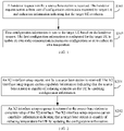
- FIG. 1 is a flow chart of a method for reducing temperature for UE in accordance with an exemplary embodiment of the present disclosure.
- the method may be performed by a target base station. As shown in FIG. 1 , the method may include the following steps.
- step S101 a handover request sent by a source base station is received.
- the handover request carries at least one of configuration information expected by target UE and indication information indicating that the target UE overheats.
- the handover request is sent to a target base station if it is determined that the target UE requires handover of the base station.
- the source base station may interact with other base stations available for handover to inform the other base stations whether it has the ability to reduce temperature for the UE by updating the configuration information. For example, when a base station sets up an X2 interface (namely, an interface between the base stations), capability information indicating whether the base station can reduce temperature for the UE by updating the configuration information or not may be carried in an X2 interface setup request and an X2 interface setup response.
- X2 interface namely, an interface between the base stations
- the source base station can choose a base station that has the ability to reduce temperature for the UE from other base stations available for handover as the target base station.
- the handover request sent by the source base station may carry at least one of the configuration information expected by the target UE and the indication information indicating that the target UE overheats. If the source base station, but not the target base station, has the ability to reduce temperature for the UE, the handover request sent by the source station does not carry at least one of the configuration information expected by the target UE and the indication information indicating that the target UE overheats.
- Overheating of the target UE may present in various forms, including but not limited to the temperature of the UE being higher than a preset temperature, the temperature of the UE being higher than the preset temperature and lasting for a period of time, etc.
- step S102 first configuration information is sent to the target UE based on the handover request.
- the first configuration information is configured for the target UE to update its own radio communication parameter configuration so as to reduce its own temperature.
- the first configuration information may be the same as or different from the configuration information expected by the target UE.
- the target base station can send the first configuration information to the target UE after receiving the handover request.
- the first configuration information may be the configuration information expected by the target UE and may also be new configuration information generated by the target base station with reference to the configuration information expected by the target UE, i.e., the first configuration information is different from the configuration information expected by the target UE.
- the target UE can update its own radio communication parameter configuration and reduce its own temperature after receiving the first configuration information. Thus, such problems as service interruption or UE restart caused by overheating of the UE may be avoided.
- the target base station may send the first configuration information to the target UE after receiving the handover request.
- the radio communication parameter configuration identified by the first configuration information is lower than the radio communication parameter configuration obtained before the target UE receives the first configuration information. In this way, the temperature of the target UE can be reduced after the target UE updates its own radio communication parameter configuration based on the received first configuration information. Thus, such problems as service interruption or UE restart caused by overheating of the UE may be avoided.
- the handover request sent by the source base station is received, and the first configuration information is sent to the target UE based on information carried in the handover request, such that the temperature of the target UE can be reduced after the target UE updates its own radio communication parameter configuration based on the first configuration information.
- problems caused by overheating of the UE may be avoided.
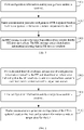
- FIG. 2 is a flow chart of a method for reducing temperature for UE in accordance with an exemplary embodiment of the present disclosure. As shown in FIG. 2 , before the step S101, the method may further include the following steps.
- step S201 an X2 interface setup request sent by a source base station is received.
- the X2 interface setup request carries capability information indicating that the source base station is capable of reducing temperature for the UE by updating configuration information.
- the source base station can send the X2 interface setup request to a target base station.
- the X2 interface setup request carries the capability information indicating that the source base station is capable of reducing temperature for the UE by updating the configuration information.
- step S202 an X2 interface setup response is returned to the source base station to complete setup of the X2 interface.
- the X2 interface setup response carries capability information indicating that a target base station is capable of reducing temperature for the UE by updating the configuration information.
- the target base station After receiving the X2 interface setup request, the target base station extracts the capability information indicating that the source base station is capable of reducing temperature for the UE by updating the configuration information from the received X2 interface setup request and returns the X2 interface setup response to the source base station.
- the X2 interface setup response carries the capability information indicating that the target base station is capable of reducing temperature for the UE by updating the configuration information. So far, both of the source base station and the target base station can learn about whether the other party has the ability to reduce temperature for the UE by updating the configuration information.
- the X2 interface setup request sent by the source base station is received to learn about that the source base station has the ability to reduce temperature for the UE by updating the configuration information based on the capability information carried in the X2 interface setup request.
- the X2 interface setup response is returned to the source base station, such that the source base station can learn about that the target base station has the ability to reduce temperature for the UE by updating the configuration information based on the capability information carried in the X2 interface setup response.
- a condition is provided for subsequently transmitting the first configuration information to the target UE so as to reduce temperature for the target UE.
- FIG. 3 is a flow chart of a method for reducing temperature for UE in accordance with an exemplary embodiment. The method may be performed by interaction among a source base station, a target base station and a target UE. As shown in FIG. 3 , the method may include the following steps.
- a source base station sends an X2 interface setup request to a target base station.
- the X2 interface setup request carries capability information indicating that the source base station is capable of reduce temperature for the UE by updating configuration information.
- step S302 after receiving the X2 interface setup request, the target base station resolves the capability information indicating that the source base station is capable of reduce temperature for the UE by updating the configuration information from the X2 interface setup request, and returns an X2 interface setup response to the source base station to complete setup of the X2 interface.
- the X2 interface setup response carries capability information indicating that a target base station is capable of reduce temperature for the UE by updating configuration information.
- step S303 the source base station sends a handover request to the target base station through the X2 interface.
- the handover request carries at least one of configuration information expected by the target UE and indication information indicating that the target UE overheats.
- the source base station may send information reported by the overheated target UE to the target base station through the X2 interface.
- the information reported by the overheated target UE may include but not limited to at least one of the configuration information expected by the target UE and the indication information indicating that the target UE overheats.
- step S304 the target base station sends first configuration information to the target UE based on the handover request.
- the target base station can send the first configuration information to the target UE by many manners.
- the target base station can send the first configuration information to the target UE by broadcasting, or by paging message, or through the source base station.
- the target base station supports and agrees that overheating of the target UE may be solved by updating the configuration after receiving a handover request acknowledge message, the first configuration information may be sent to the target UE.
- step S305 the target base station returns the handover request acknowledge message that carries the first configuration information to the source base station.
- the target base station may inform the source base station of the configuration by the target base station to the overheated target UE through the handover request acknowledge message.
- step S306 the target UE updates its own radio communication parameter configuration based on the first configuration information to reduce its own temperature.
- step S307 the target UE sends a radio resource control (RRC) message to the target base station if it is detected that the target UE does not overheat.
- RRC radio resource control
- the RRC message carries identification information indicating that the target UE does not overheat.
- the target UE may send the identification information indicating that the target UE does not overheat to the target base station through the RRC message to inform the target base station that the problem of overheating is solved.
- the overheated target UE may update its own radio communication parameter configuration based on the first configuration information sent by the target base station.
- the target UE may not overheat immediately after the handover is completed.
- FIG. 4 is a flow chart of a method for reducing temperature for UE in accordance with an exemplary embodiment of the present disclosure. The method may be performed by the UE. As shown in FIG. 4 , the method may include the following steps.
- step S401 first configuration information sent by a target base station is received.
- the target base station may send the first configuration information to target UE based on information carried in a handover request after receiving the handover request sent by a source base station.
- radio communication parameter configuration of the UE is updated based on the first configuration information to reduce temperature for the UE.
- the target UE may update its own radio communication parameter configuration and reduce its own temperature after receiving the first configuration information. Thus, such problems as service interruption or UE restart caused by overheating of the UE may be avoided.
- the first configuration information sent by the target base station is received, and the radio communication parameter configuration of the UE is updated based on the first configuration information to reduce temperature for the UE, such that problems caused by overheating of the UE may be avoided.
- FIG. 5 is a flow chart of a method for reducing temperature for UE in accordance with an exemplary embodiment of the present disclosure. As shown in FIG. 5 , after the step S402, the method for temperature reduction of the UE may further include the following steps.
- step S403 an RRC message is sent to the target base station if it is detected that the UE does not overheat.
- the RRC message carries identification information indicating that the UE does not overheat.
- Non-overheating of the target UE may present in various forms.
- the temperature of the UE is lower than a preset temperature, or the temperature of the UE is lower than the preset temperature and lasts for a period of time.
- the identification information indicating that the UE does not overheat may be sent to the target base station through the RRC message to inform the target base station that the problem of overheating is solved.
- FIG. 6 is a block diagram of a method for reducing temperature for UE in accordance with an exemplary embodiment of the present disclosure. As shown in FIG. 6 , before the step S401, the method may further include the following step.
- step S400 if it is detected that UE overheats, at least one of configuration information expected by the UE and identification information indicating that the UE overheats is sent to a source base station in communication connection with a target base station.
- Overheating of the target UE may present in various forms.
- the temperature of the UE is higher than a preset temperature, or the temperature of the UE is higher than the preset temperature and lasts for a period of time.
- At least one of the configuration information expected by the UE and the identification information indicating that the UE overheats may be sent to the source base station, such that when the source base station sends the handover request to the target base station, a handover request may carry at least one of the configuration information expected by the UE and identification information indicating that the UE overheats.
- a condition is provided for the target base station to send the first configuration information to the UE so as to reduce temperature for the UE.
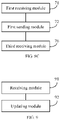
- FIG. 7 is a block diagram of a device for reducing temperature for UE in accordance with an exemplary embodiment. As shown in FIG. 7 , the device includes a first receiving module 71 and a first sending module 72.
- the first receiving module 71 is configured to receive a handover request sent by a source base station.
- the handover request carries at least one of configuration information expected by target UE and indication information indicating that the target UE overheats.
- the handover request is sent to a target base station if it is determined that the target UE requires handover of the base station.
- the source base station may interact with other base stations available for handover to inform the other base stations whether it has the ability to reduce temperature for the UE by updating the configuration information. For example, when the base station sets up an X2 interface (namely, an interface between the base stations), capability information indicating whether the base station can reduce temperature for the UE by updating the configuration information or not may be carried in an X2 interface setup request and an X2 interface setup response.
- an X2 interface namely, an interface between the base stations
- capability information indicating whether the base station can reduce temperature for the UE by updating the configuration information or not may be carried in an X2 interface setup request and an X2 interface setup response.
- the source base station can choose a base station that has the ability to reduce temperature for the UE from other base stations available for handover as the target base station.
- the handover request sent by the source base station can carry at least one of the configuration information expected by the target UE and the indication information indicating that the target UE overheats. If the source base station but not the target base station has the ability to reduce temperature for the UE, the handover request sent by the source station does not carry at least one of the configuration information expected by the target UE and the indication information indicating that the target UE overheats.
- Overheating of the target UE may present in various forms, including but not limited to the temperature of the UE being higher than a preset temperature, the temperature of the UE being higher than the preset temperature and lasts for a period of time, etc.
- the first sending module 72 is configured to send first configuration information to the target UE based on the handover request received by the first receiving module 71.
- the first configuration information is configured for the target UE to update its own radio communication parameter configuration so as to reduce its own temperature.
- the first configuration information is the same as or different from the configuration information expected by the target UE
- the target base station can send the first configuration information to the target UE after receiving the handover request.
- the first configuration information may be the configuration information expected by the target UE and may also be new configuration information generated by the target base station with reference to the configuration information expected by the target UE, i.e., the first configuration information is different from the configuration information expected by the target UE.
- the target UE may update its own radio communication parameter configuration and reduce its own temperature after receiving the first configuration information. Thus, such problems as service interruption or UE restart caused by overheating of the UE may be avoided.
- the target base station may send the first configuration information to the target UE after receiving the handover request.
- the radio communication parameter configuration identified by the first configuration information is lower than the radio communication parameter configuration obtained before the target UE receives the first configuration information. In this way, the temperature of the target UE can be reduced after the target UE updates its own radio communication parameter configuration based on the received first configuration information. Thus, such problems as service interruption or UE restart caused by overheating of the UE may be avoided.
- the handover request sent by the source base station is received, and the first configuration information is sent to the target UE based on information carried in the handover request, such that the temperature of the target UE can be reduced after the target UE updates its own radio communication parameter configuration based on the first configuration information.
- problems caused by overheating of the UE may be avoided.
- FIG. 8A is a block diagram of a device for reducing temperature for UE in accordance with an exemplary embodiment. As shown in FIG. 8A , based on the embodiment shown in FIG. 7 , the device may further include a second receiving module 73 and a first returning module 74.
- the second receiving module 73 is configured to, before the first receiving module 71 receives the handover request sent by the source base station, receive an X2 interface setup request sent by the source base station.
- the X2 interface setup request carries capability information indicating that the source base station is capable of reducing temperature for the UE by updating the configuration information.
- the source base station can send the X2 interface setup request to a target base station.
- the X2 interface setup request carries the capability information indicating that the source base station is capable of reducing temperature for the UE by updating the configuration information.
- the first returning module 74 is configured to return an X2 interface setup response of the X2 interface building request received by the second receiving module to the source base station to complete setup of an X2 interface.
- the X2 interface setup request carries capability information indicating that a target base station is capable of reducing temperature for the UE by updating the configuration information.
- the target base station After receiving the X2 interface setup request, the target base station extracts the capability information indicating that the source base station is capable of reducing temperature for the UE by updating the configuration information from the received X2 interface setup request and returns the X2 interface setup response to the source base station.
- the X2 interface setup response carries the capability information indicating that the target base station is capable of reducing temperature for the UE by updating the configuration information. So far, both of the source base station and the target base station can learn about whether the other party has the ability to reduce temperature for the UE by updating the configuration information.
- the X2 interface setup request sent by the source base station is received to learn about that the source base station has the ability to reduce temperature for the UE by updating the configuration information based on the capability information carried in the X2 interface setup request.
- the X2 interface setup response is returned to the source base station, such that the source base station can learn about that the target base station has the ability to reduce temperature for the UE by updating the configuration information based on the capability information carried in the X2 interface setup response.
- a condition is provided for subsequently transmitting the first configuration information to the target UE so as to reduce temperature for the target UE.
- FIG. 8B is a block diagram of a device for reducing temperature for UE in accordance with an exemplary embodiment. As shown in FIG. 8B , based on the embodiment shown in FIG. 7 , the device may further include a second returning module 75.
- the second returning module 75 is configured to, after the first sending module 72 sends the first configuration information to the target UE based on the handover request, return a handover request acknowledge message that carries the first configuration information to the source base station.
- the target base station may inform the source base station of the configuration by the target base station to the overheated target UE through the handover request acknowledge message.
- the handover request response message is returned to the source base station to inform the source base station of the configuration by the target base station to the overheated target UE.
- FIG. 8C is a block diagram of a device for reducing temperature for UE in accordance with an exemplary embodiment. As shown in FIG. 8C , based on the embodiment shown in FIG. 7 , the device may further include a third receiving module 76.
- the third receiving module 76 is configured to, after the first sending module 72 sends the first configuration information to the target UE based on the handover request, receive an RRC message sent by the target UE.
- the RRC message carries identification information indicating that the target UE does not overheat.
- the target UE may send the identification information indicating that the target UE does not overheat to the target base station through the RRC message to inform the target base station that the problem of overheating is solved.
- the identification information indicating that the target UE does not overheat may be sent to the target base station through the RRC message to inform the target base station that the problem of overheating is solved.
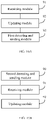
- FIG. 9 is a block diagram of a device for reducing temperature for UE in accordance with an exemplary embodiment. As shown in FIG. 9 , the device includes a receiving module 91 and an updating module 92.
- the receiving module 91 is configured to receive first configuration information sent by a target base station.
- the target base station may send the first configuration information to target UE based on information carried in a handover request.
- the updating module 92 is configured to update radio communication parameter configuration of UE based on the first configuration information to reduce temperature for the UE.
- the target UE may update its own radio communication parameter configuration after receiving the first configuration information to reduce its own temperature. Thus, such problems as service interruption or UE restart caused by overheating of the UE may be avoided.
- the first configuration information sent by the target base station is received, and the radio communication parameter configuration of the UE is updated based on the first configuration information to reduce temperature for the UE, such that problems caused by overheating of the UE may be avoided.
- FIG. 10A is a block diagram of a device for reducing temperature for UE in accordance with an exemplary embodiment. As shown in FIG. 10A , based on the embodiment shown in FIG. 9 , the device may further include a first detecting and sending module 93.
- the first detecting and sending module 93 is configured to, after the updating module 92 updates the radio communication parameter configuration of the UE based on the first configuration information, send an RRC message to the target base station if it is detected that the UE does not overheat.
- the RRC message carries identification information indicating that the UE does not overheat.
- the identification information indicating that the UE does not overheat may be sent to the target base station through the RRC message to inform the target base station that the problem of overheating is solved.
- FIG. 10B is a block diagram of a device for reducing temperature for UE in accordance with an exemplary embodiment. As shown in FIG. 10B , based on the embodiment shown in FIG. 9 , the device may further include a second detecting and sending module 90.
- the second detecting and sending module 90 is configured to, before the receiving module 91 receives the first configuration information sent by the target base station, send at least one of configuration information expected by the UE and identification information indicating that the UE overheats to a source base station in communication connection with the target base station if it is detected that the UE overheats.
- Overheating of the target UE may present in various forms.
- the temperature of the UE is higher than a preset temperature, or the temperature of the UE is higher than the preset temperature and lasts for a period of time.
- At least one of the configuration information expected by the UE and the identification information indicating that the UE overheats may be sent to the source base station, such that when the source base station sends the handover request to the target base station, a handover request may carry at least one of the configuration information expected by the UE and the identification information indicating that the UE overheats.
- a condition is provided for the target base station to send the first configuration information to the UE so as to reduce temperature for the UE.
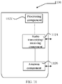
- FIG. 11 is a block diagram of a device 1100 for reducing temperature for UE in accordance with an exemplary embodiment.
- the device 1100 may be provided as a base station.
- the device 1100 includes a processing component 1122, a radio transmitting/receiving component 1124, an antenna component 1126, and a signal processing portion peculiar to a radio interface.
- the processing component 1122 may further include one or more processors configured to: receive a handover request sent by a source base station, wherein the handover request carries at least one of configuration information expected by target UE and indication information indicating that the target UE overheats; and send first configuration information to the target UE based on the handover request, wherein the first configuration information is configured for the target UE to update its own radio communication parameter configuration so as to reduce its own temperature, and the first configuration information may be the same as or different from the configuration information expected by the target UE.
- FIG. 12 is a block diagram of a device 1200 for reducing temperature for UE in accordance with an exemplary embodiment.
- the device 1200 may be UE, a mobile phone, a computer, a digital broadcast terminal, a messaging device, a gaming console, a tablet device, a medical device, a fitness equipment, a personal digital assistant, and the like.
- the device 1200 may include one or more of the following components: a processing component 1202, a memory 1204, a power component 1206, a multimedia component 1208, an audio component 1210, an input/output (I/O) interface 1212, a sensor component 1214, and a communication component 1216.
- a processing component 1202 a memory 1204, a power component 1206, a multimedia component 1208, an audio component 1210, an input/output (I/O) interface 1212, a sensor component 1214, and a communication component 1216.
- the processing component 1202 typically controls the overall operations of the device 1200, such as the operations associated with display, telephone calls, data communications, camera operations, and recording operations.
- the processing component 1202 may include one or more processors 1220 to execute instructions to perform all or part of the steps in the above described methods.
- the processing component 1202 may include one or more modules which facilitate the interaction between the processing component 1202 and other components.
- the processing component 1202 may include a multimedia module to facilitate the interaction between the multimedia component 1208 and the processing component 1202.
- the memory 1204 is configured to store various types of data to support the operation of the device 1200. Examples of such data include instructions for any applications or methods operated on the device 1200, contact data, phonebook data, messages, pictures, videos, etc.
- the memory 1204 may be implemented by using any type of volatile or non-volatile memory devices, or a combination thereof, such as a static random access memory (SRAM), an electrically erasable programmable read-only memory (EEPROM), an erasable programmable read-only memory (EPROM), a programmable read-only memory (PROM), a read-only memory (ROM), a magnetic memory, a flash memory, a magnetic or optical disk.
- SRAM static random access memory
- EEPROM electrically erasable programmable read-only memory
- EPROM erasable programmable read-only memory
- PROM programmable read-only memory
- ROM read-only memory
- magnetic memory a magnetic memory
- flash memory a flash memory
- magnetic or optical disk a
- the power component 1206 provides power to various components of the device 1200.
- the power component 1206 may include a power management system, one or more power sources, and any other components associated with the generation, management, and distribution of power in the device 1200.
- the multimedia component 1208 includes a screen providing an output interface between the device 1200 and the user.
- the screen may include a liquid crystal display (LCD) and a touch panel (TP). If the screen includes the touch panel, the screen may be implemented as a touch screen to receive input signals from the user.
- the touch panel includes one or more touch sensors to sense touches, swipes, and gestures on the touch panel. The touch sensors may not only sense a boundary of a touch or swipe action, but also sense the duration and pressure associated with the touch or swipe action.
- the multimedia component 1208 includes a front camera and/or a rear camera. The front camera and the rear camera may receive external multimedia data while the device 1200 is in an operation mode, such as a photographing mode or a video mode. Each of the front camera and the rear camera may be a fixed optical lens system or have focus and optical zoom capability.
- the audio component 1210 is configured to output and/or input audio signals.
- the audio component 1210 includes a microphone (MIC) configured to receive external audio signals when the device 1200 is in an operation mode, such as a call mode, a recording mode, and a voice recognition mode.
- the received audio signal may be further stored in the memory 1204 or transmitted via the communication component 1216.
- the audio component 1210 further includes a speaker for outputting audio signals.
- the I/O interface 1212 provides an interface between the processing component 1202 and peripheral interface modules, such as a keyboard, a click wheel, buttons, and the like.
- the buttons may include, but are not limited to, a home button, a volume button, a start button, and a lock button.
- the sensor component 1214 includes one or more sensors to provide status assessments of various aspects of the device 1200. For instance, the sensor component 1214 may detect an on/off status of the device 1200, relative positioning of components, e.g., the display device and the mini keyboard of the device 1200, and the sensor component 1214 may also detect a position change of the device 1200 or a component of the device 1200, presence or absence of user contact with the device 1200, orientation or acceleration/deceleration of the device 1200, and temperature change of the device 1200.
- the sensor component 1214 may include a proximity sensor configured to detect the presence of nearby objects without any physical contact.
- the sensor component 1214 may also include a light sensor, such as a CMOS or CCD image sensor, used for imaging applications.
- the sensor component 1214 may also include an accelerometer sensor, a gyroscope sensor, a magnetic sensor, a pressure sensor, or a temperature sensor.
- the communication component 1216 is configured to facilitate communication, wired or wirelessly, between the device 1200 and other devices.
- the device 1200 can access a wireless network based on a communication standard, such as WiFi, 4G, or 5G, or a combination thereof.
- the communication component 1216 receives broadcast signals or broadcast associated information from an external broadcast management system via a broadcast channel.
- the communication component 1216 further includes a near field communication (NFC) module to facilitate short-range communications.
- NFC near field communication
- the communication component 1216 may be implemented based on a radio frequency identification (RFID) technology, an infrared data association (IrDA) technology, an ultra-wideband (UWB) technology, a Bluetooth (BT) technology, and other technologies.
- RFID radio frequency identification
- IrDA infrared data association
- UWB ultra-wideband
- BT Bluetooth
- the device 1200 may be implemented with one or more application specific integrated circuits (ASICs), digital signal processors (DSPs), digital signal processing devices (DSPDs), programmable logic devices (PLDs), field programmable gate arrays (FPGAs), controllers, micro-controllers, microprocessors, or other electronic components, for performing the above described methods.
- ASICs application specific integrated circuits
- DSPs digital signal processors
- DSPDs digital signal processing devices
- PLDs programmable logic devices
- FPGAs field programmable gate arrays
- controllers micro-controllers, microprocessors, or other electronic components, for performing the above described methods.
- a non-transitory computer-readable storage medium including instructions is also provided, such as the memory 1204 including instructions, executable by the processor 1220 in the device 1200, for performing the above-described methods.
- the non-transitory computer-readable storage medium may be a ROM, a RAM, a CD-ROM, a magnetic tape, a floppy disc, an optical data storage device, and the like.
- modules illustrated as separate components may or may not be physically separate, for example, the modules may be in one place or distributed on multiple networks. Part or all of the modules may be selected according to actual needs to achieve the purpose of the solutions of the device embodiments.
Landscapes
- Engineering & Computer Science (AREA)
- Computer Networks & Wireless Communication (AREA)
- Signal Processing (AREA)
- Theoretical Computer Science (AREA)
- Physics & Mathematics (AREA)
- General Engineering & Computer Science (AREA)
- General Physics & Mathematics (AREA)
- Human Computer Interaction (AREA)
- Computer Hardware Design (AREA)
- Quality & Reliability (AREA)
- Mobile Radio Communication Systems (AREA)
Abstract
Description
- The present disclosure relates to the field of communication technology and in particular, to methods and devices for reducing temperature for user equipment (UE).
- With the development of mobile communication technologies, users are demanding greater transmission rates. Long term evolution (LTE) UE can obtain an ultrahigh transmission rate by configuring high-order multiple-input multi-output (MIMO), multi-carrier aggregation, high-order modulation and coding or the like to meet the user's demand for a high rate.
- However, these technologies that bring about high-rate transmission may cause the UE to overheat.
- The present disclosure provides methods and devices for reducing temperature for user equipment (UE).
According to a first aspect of the present disclosure, there is provided a method for reducing temperature for UE as defined by claim 1. - In some embodiments, prior to receiving the handover request sent by the source base station, the method further includes:
- receiving an X2 interface setup request sent by the source base station, wherein the X2 interface setup request carries capability information indicating that the source base station is capable of cooling down the UE by updating the configuration information; and
- transmitting an X2 interface setup response to the source base station to establish the X2 interface, wherein the X2 interface setup response carries capability information indicating that a current target base station is capable of cooling down the UE by updating the configuration information.
- In some embodiments, after sending the first configuration information to the target UE based on the handover request, the method further comprises:
transmitting a handover request acknowledge message that carries the first configuration information to the source base station. - In some embodiments, after the sending the first configuration information to the target UE based on the handover request, the method further comprises:
receiving a radio resource control (RRC) message sent by the target UE, wherein the RRC message carries identification information indicating that the target UE does not overheat. - In some embodiments, the receiving the handover request sent by the source base station comprises:
receiving the handover request by the X2 interface.
According to a second aspect of the present disclosure, there is provided a method for reducing temperature for UE as defined by claim 6. - In some embodiments, after updating the radio communication parameter configuration of the current UE based on the first configuration information, the method further includes:
sending an RRC message to the target base station if it is detected that the current UE does not overheat, wherein the RRC message carries identification information indicating that the current UE does not overheat. - In some embodiments, prior to receiving the first configuration information sent by the target base station, the method further comprises:
if it is detected that the current UE overheat, sending at least one of configuration information expected by the current UE and identification information indicating that the current UE overheats to a source base station that establishes a communication connection with the target base station. - Also described is a device for temperature reduction of UE, including:
- a first receiving module configured to receive a handover request sent by a source base station, wherein the handover request carries at least one of configuration information expected by target UE and indication information indicating that the target UE overheats; and
- a first sending module configured to send first configuration information to the target UE based on the handover request, wherein the first configuration information is configured for the target UE to update its own radio communication parameter configuration so as to reduce the temperature of the UE, and the first configuration information is the same as or different from the configuration information expected by the target UE.
- In some embodiments, the device further includes:
- a second receiving module configured to, prior to the handover request sent by the source base station is received, receive an X2 interface setup request sent by the source base station, wherein the X2 interface setup request carries capability information indicating that the source base station is capable of cooling down the UE by updating the configuration information; and
- a first returning module configured to transmit an X2 interface setup response to the source base station to establish the X2 interface, wherein the X2 interface setup response carries capability information indicating that a current target base station is capable of cooling down the UE by updating the configuration information.
- In some embodiments, the device further includes:
a second returning module configured to, after the first sending module sends the first configuration information to the target UE based on the handover request, transmit a handover request acknowledge message that carries the first configuration information to the source base station. - In some embodiments, the device further includes:
a third receiving module configured to, after the first sending module sends the first configuration information to the target UE based on the handover request, receive a radio resource control (RRC) message sent by the target UE, wherein the RRC message carries identification information indicating that the target UE does not overheat. - In some embodiments, the first receiving module is configured to:
receive the handover request by the X2 interface. - Also described is a device for temperature reduction of UE, including:
- a receiving module configured to receive first configuration information sent by a target base station; and
- an updating module configured to update radio communication parameter configuration of current UE based on the first configuration information to reduce the temperature of the current UE.
- In some embodiments, the device further includes:
a first detecting and sending module configured to, after the updating module updates the radio communication parameter configuration of the current UE based on the first configuration information, send an RRC message to the target base station if it is detected that the current UE does not overheat, wherein the RRC message carries identification information indicating that the current UE does not overheat. - In some embodiments, the device further includes:
- a second detecting and sending module configured to, prior to the receiving module receives the first configuration information sent by the target base station, send at least one of configuration information expected by the current UE and identification information indicating that the current UE overheats to a source base station that establishes a communication connection with the target base station if it is detected that the current UE overheat.
- According to another aspect of the present disclosure, there is provided a first base station as defined by claim 9.
- According to another aspect of the present disclosure, there is provided user equipment (UE) as defined by claim 10.
- after updating the radio communication parameter configuration of the current UE based on the first configuration information, further comprising:
send an RRC message to the target base station if it is detected that the current UE does not overheat, wherein the RRC message carries identification information indicating that the current UE does not overheat. - In some embodiments, prior to receiving the first configuration information sent by the target base station, further comprising:
if it is detected that the current UE overheat, send at least one of configuration information expected by the current UE and identification information indicating that the current UE overheats to a source base station that establishes a communication connection with the target base station. - According to a another aspect of the present disclosure, there is provided a computer-readable storage medium with a computer program stored thereon, wherein the method for reducing temperature for the UE is implemented when the computer program is executed by the processor.
- According to an another aspect of the present disclosure, there is provided a computer-readable storage medium with a computer program stored thereon, wherein the method for reducing temperature for the UE is implemented when the computer program is executed by the processor.
- The technical solutions provided by the embodiments of the present disclosure may have the following beneficial effects.
- Because the handover request is received from the source base station, and the first configuration information is sent to the UE based on information carried in the handover request, the temperature of the UE can be reduced after the UE updates its own radio communication parameter configuration based on the first configuration information. Thus, problems caused by overheating of the UE can be avoided.
- Because the first configuration information sent by the target base station is received, and the radio communication parameter configuration of the UE is updated based on the first configuration information to reduce temperature for the UE, problems caused by overheating of the UE can be avoided.
- It is to be understood that both the foregoing general description and the following detailed description are exemplary and explanatory only and are intended to limit the present disclosure.
-
-
FIG. 1 is a flow chart of a method for reducing temperature for UE in accordance with an exemplary embodiment. -
FIG. 2 is a flow chart of a method for reducing temperature for UE in accordance with an exemplary embodiment. -
FIG. 3 is a flow chart of a method for reducing temperature for UE in accordance with an exemplary embodiment. -
FIG. 4 is a flow chart of a method for reducing temperature for UE in accordance with an exemplary embodiment. -
FIG. 5 is a flow chart of a method for reducing temperature for UE in accordance with an exemplary embodiment. -
FIG. 6 is a flow chart of a method for reducing temperature for UE in accordance with an exemplary embodiment. -
FIG. 7 is a block diagram of a device for reducing temperature for UE in accordance with an exemplary embodiment. -
FIG. 8A is a block diagram of a device for reducing temperature for UE in accordance with an exemplary embodiment. -
FIG. 8B is a block diagram of a device for reducing temperature for UE in accordance with an exemplary embodiment. -
FIG. 8C is a block diagram of a device for reducing temperature for UE in accordance with an exemplary embodiment. -
FIG. 9 is a block diagram of a device for reducing temperature for UE in accordance with an exemplary embodiment. -
FIG. 10A is a block diagram of a device for reducing temperature for UE in accordance with an exemplary embodiment. -
FIG. 10B is a block diagram of a device for reducing temperature for UE in accordance with an exemplary embodiment. -
FIG. 11 is a block diagram of a device for reducing temperature for UE in accordance with an exemplary embodiment. -
FIG. 12 is a block diagram of a device for reducing temperature for UE in accordance with an exemplary embodiment. - The present disclosure will be described in detail below in combination with the accompanying drawings. The described embodiments are merely exemplary embodiments, rather than all embodiments consistent with the present disclosure. Based on the embodiments of the present disclosure, all other embodiments derived by a person of ordinary skill in the art without creative efforts shall fall within the protection scope of the invention as defined by the claims.
-
FIG. 1 is a flow chart of a method for reducing temperature for UE in accordance with an exemplary embodiment of the present disclosure. The method may be performed by a target base station. As shown inFIG. 1 , the method may include the following steps. - In step S101, a handover request sent by a source base station is received. The handover request carries at least one of configuration information expected by target UE and indication information indicating that the target UE overheats.
- After the source station receives a measurement signal reported by the target UE, the handover request is sent to a target base station if it is determined that the target UE requires handover of the base station.
- In this embodiment, before execution of step S101, the source base station may interact with other base stations available for handover to inform the other base stations whether it has the ability to reduce temperature for the UE by updating the configuration information. For example, when a base station sets up an X2 interface (namely, an interface between the base stations), capability information indicating whether the base station can reduce temperature for the UE by updating the configuration information or not may be carried in an X2 interface setup request and an X2 interface setup response.
- Supposing that the source base station has the ability to reduce temperature for the UE, the source base station can choose a base station that has the ability to reduce temperature for the UE from other base stations available for handover as the target base station. In addition, after it is determined that both of the base stations have the ability to reduce temperature for the UE, the handover request sent by the source base station may carry at least one of the configuration information expected by the target UE and the indication information indicating that the target UE overheats. If the source base station, but not the target base station, has the ability to reduce temperature for the UE, the handover request sent by the source station does not carry at least one of the configuration information expected by the target UE and the indication information indicating that the target UE overheats.
- Overheating of the target UE may present in various forms, including but not limited to the temperature of the UE being higher than a preset temperature, the temperature of the UE being higher than the preset temperature and lasting for a period of time, etc.
- In step S102, first configuration information is sent to the target UE based on the handover request. The first configuration information is configured for the target UE to update its own radio communication parameter configuration so as to reduce its own temperature. The first configuration information may be the same as or different from the configuration information expected by the target UE.
- If the handover request carries the configuration information expected by the target UE, the target base station can send the first configuration information to the target UE after receiving the handover request. The first configuration information may be the configuration information expected by the target UE and may also be new configuration information generated by the target base station with reference to the configuration information expected by the target UE, i.e., the first configuration information is different from the configuration information expected by the target UE. The target UE can update its own radio communication parameter configuration and reduce its own temperature after receiving the first configuration information. Thus, such problems as service interruption or UE restart caused by overheating of the UE may be avoided.
- If the handover request only carries the indication information indicating that the target UE overheats, the target base station may send the first configuration information to the target UE after receiving the handover request. The radio communication parameter configuration identified by the first configuration information is lower than the radio communication parameter configuration obtained before the target UE receives the first configuration information. In this way, the temperature of the target UE can be reduced after the target UE updates its own radio communication parameter configuration based on the received first configuration information. Thus, such problems as service interruption or UE restart caused by overheating of the UE may be avoided.
- In the foregoing embodiment, the handover request sent by the source base station is received, and the first configuration information is sent to the target UE based on information carried in the handover request, such that the temperature of the target UE can be reduced after the target UE updates its own radio communication parameter configuration based on the first configuration information. Thus, problems caused by overheating of the UE may be avoided.
-
FIG. 2 is a flow chart of a method for reducing temperature for UE in accordance with an exemplary embodiment of the present disclosure. As shown inFIG. 2 , before the step S101, the method may further include the following steps. - In step S201, an X2 interface setup request sent by a source base station is received. The X2 interface setup request carries capability information indicating that the source base station is capable of reducing temperature for the UE by updating configuration information.
- In this embodiment, the source base station can send the X2 interface setup request to a target base station. The X2 interface setup request carries the capability information indicating that the source base station is capable of reducing temperature for the UE by updating the configuration information.
- In step S202, an X2 interface setup response is returned to the source base station to complete setup of the X2 interface. The X2 interface setup response carries capability information indicating that a target base station is capable of reducing temperature for the UE by updating the configuration information.
- After receiving the X2 interface setup request, the target base station extracts the capability information indicating that the source base station is capable of reducing temperature for the UE by updating the configuration information from the received X2 interface setup request and returns the X2 interface setup response to the source base station. The X2 interface setup response carries the capability information indicating that the target base station is capable of reducing temperature for the UE by updating the configuration information. So far, both of the source base station and the target base station can learn about whether the other party has the ability to reduce temperature for the UE by updating the configuration information.
- In the foregoing embodiment, the X2 interface setup request sent by the source base station is received to learn about that the source base station has the ability to reduce temperature for the UE by updating the configuration information based on the capability information carried in the X2 interface setup request. Meanwhile, the X2 interface setup response is returned to the source base station, such that the source base station can learn about that the target base station has the ability to reduce temperature for the UE by updating the configuration information based on the capability information carried in the X2 interface setup response. Thus, a condition is provided for subsequently transmitting the first configuration information to the target UE so as to reduce temperature for the target UE.
-
FIG. 3 is a flow chart of a method for reducing temperature for UE in accordance with an exemplary embodiment. The method may be performed by interaction among a source base station, a target base station and a target UE. As shown inFIG. 3 , the method may include the following steps. - In step S301, a source base station sends an X2 interface setup request to a target base station. The X2 interface setup request carries capability information indicating that the source base station is capable of reduce temperature for the UE by updating configuration information.
- In step S302, after receiving the X2 interface setup request, the target base station resolves the capability information indicating that the source base station is capable of reduce temperature for the UE by updating the configuration information from the X2 interface setup request, and returns an X2 interface setup response to the source base station to complete setup of the X2 interface. The X2 interface setup response carries capability information indicating that a target base station is capable of reduce temperature for the UE by updating configuration information.
- In step S303, the source base station sends a handover request to the target base station through the X2 interface. The handover request carries at least one of configuration information expected by the target UE and indication information indicating that the target UE overheats.
- During handover of the overheated target UE, the source base station may send information reported by the overheated target UE to the target base station through the X2 interface. The information reported by the overheated target UE may include but not limited to at least one of the configuration information expected by the target UE and the indication information indicating that the target UE overheats.
- In step S304, the target base station sends first configuration information to the target UE based on the handover request.
- In some embodiments, the target base station can send the first configuration information to the target UE by many manners. For example, the target base station can send the first configuration information to the target UE by broadcasting, or by paging message, or through the source base station.
- If the target base station supports and agrees that overheating of the target UE may be solved by updating the configuration after receiving a handover request acknowledge message, the first configuration information may be sent to the target UE.
- In step S305, the target base station returns the handover request acknowledge message that carries the first configuration information to the source base station.
- After sending the first configuration information to the target UE, the target base station may inform the source base station of the configuration by the target base station to the overheated target UE through the handover request acknowledge message.
- In step S306, the target UE updates its own radio communication parameter configuration based on the first configuration information to reduce its own temperature.
- In step S307, the target UE sends a radio resource control (RRC) message to the target base station if it is detected that the target UE does not overheat. The RRC message carries identification information indicating that the target UE does not overheat.
- After the problem of overheating is solved, the target UE may send the identification information indicating that the target UE does not overheat to the target base station through the RRC message to inform the target base station that the problem of overheating is solved.
- In the foregoing embodiment, through interaction among the source base station, the target base station and the target UE, the overheated target UE may update its own radio communication parameter configuration based on the first configuration information sent by the target base station. Thus, the target UE may not overheat immediately after the handover is completed.
-
FIG. 4 is a flow chart of a method for reducing temperature for UE in accordance with an exemplary embodiment of the present disclosure. The method may be performed by the UE. As shown inFIG. 4 , the method may include the following steps. - In step S401, first configuration information sent by a target base station is received.
- The target base station may send the first configuration information to target UE based on information carried in a handover request after receiving the handover request sent by a source base station.
- In step S402, radio communication parameter configuration of the UE is updated based on the first configuration information to reduce temperature for the UE.
- The target UE may update its own radio communication parameter configuration and reduce its own temperature after receiving the first configuration information. Thus, such problems as service interruption or UE restart caused by overheating of the UE may be avoided.
- In the foregoing embodiment, the first configuration information sent by the target base station is received, and the radio communication parameter configuration of the UE is updated based on the first configuration information to reduce temperature for the UE, such that problems caused by overheating of the UE may be avoided.
-
FIG. 5 is a flow chart of a method for reducing temperature for UE in accordance with an exemplary embodiment of the present disclosure. As shown inFIG. 5 , after the step S402, the method for temperature reduction of the UE may further include the following steps. - In step S403, an RRC message is sent to the target base station if it is detected that the UE does not overheat. The RRC message carries identification information indicating that the UE does not overheat.
- Non-overheating of the target UE may present in various forms. For example, the temperature of the UE is lower than a preset temperature, or the temperature of the UE is lower than the preset temperature and lasts for a period of time.
- In the embodiment, after it is detected that the UE does not overheat, the identification information indicating that the UE does not overheat may be sent to the target base station through the RRC message to inform the target base station that the problem of overheating is solved.
-
FIG. 6 is a block diagram of a method for reducing temperature for UE in accordance with an exemplary embodiment of the present disclosure. As shown inFIG. 6 , before the step S401, the method may further include the following step. - In step S400, if it is detected that UE overheats, at least one of configuration information expected by the UE and identification information indicating that the UE overheats is sent to a source base station in communication connection with a target base station.
- Overheating of the target UE may present in various forms. For example, the temperature of the UE is higher than a preset temperature, or the temperature of the UE is higher than the preset temperature and lasts for a period of time.
- In the embodiment, after it is detected that the UE overheats, at least one of the configuration information expected by the UE and the identification information indicating that the UE overheats may be sent to the source base station, such that when the source base station sends the handover request to the target base station, a handover request may carry at least one of the configuration information expected by the UE and identification information indicating that the UE overheats. Thus, a condition is provided for the target base station to send the first configuration information to the UE so as to reduce temperature for the UE.
-
FIG. 7 is a block diagram of a device for reducing temperature for UE in accordance with an exemplary embodiment. As shown inFIG. 7 , the device includes afirst receiving module 71 and afirst sending module 72. - The
first receiving module 71 is configured to receive a handover request sent by a source base station. The handover request carries at least one of configuration information expected by target UE and indication information indicating that the target UE overheats. - After the source base station receives a measurement signal reported by the target UE, the handover request is sent to a target base station if it is determined that the target UE requires handover of the base station.
- In this embodiment, before the
first receiving module 71 receives the handover request sent by the source base station, the source base station may interact with other base stations available for handover to inform the other base stations whether it has the ability to reduce temperature for the UE by updating the configuration information. For example, when the base station sets up an X2 interface (namely, an interface between the base stations), capability information indicating whether the base station can reduce temperature for the UE by updating the configuration information or not may be carried in an X2 interface setup request and an X2 interface setup response. - Supposing that the source base station has the ability to reduce temperature for the UE, the source base station can choose a base station that has the ability to reduce temperature for the UE from other base stations available for handover as the target base station. In addition, after it is determined that both of the base stations have the ability to reduce temperature for the UE, the handover request sent by the source base station can carry at least one of the configuration information expected by the target UE and the indication information indicating that the target UE overheats. If the source base station but not the target base station has the ability to reduce temperature for the UE, the handover request sent by the source station does not carry at least one of the configuration information expected by the target UE and the indication information indicating that the target UE overheats.
- Overheating of the target UE may present in various forms, including but not limited to the temperature of the UE being higher than a preset temperature, the temperature of the UE being higher than the preset temperature and lasts for a period of time, etc.
- The
first sending module 72 is configured to send first configuration information to the target UE based on the handover request received by thefirst receiving module 71. The first configuration information is configured for the target UE to update its own radio communication parameter configuration so as to reduce its own temperature. The first configuration information is the same as or different from the configuration information expected by the target UE - If the handover request carries the configuration information expected by the target UE, the target base station can send the first configuration information to the target UE after receiving the handover request. The first configuration information may be the configuration information expected by the target UE and may also be new configuration information generated by the target base station with reference to the configuration information expected by the target UE, i.e., the first configuration information is different from the configuration information expected by the target UE. The target UE may update its own radio communication parameter configuration and reduce its own temperature after receiving the first configuration information. Thus, such problems as service interruption or UE restart caused by overheating of the UE may be avoided.
- If the handover request only carries the indication information indicating that the target UE overheats, the target base station may send the first configuration information to the target UE after receiving the handover request. The radio communication parameter configuration identified by the first configuration information is lower than the radio communication parameter configuration obtained before the target UE receives the first configuration information. In this way, the temperature of the target UE can be reduced after the target UE updates its own radio communication parameter configuration based on the received first configuration information. Thus, such problems as service interruption or UE restart caused by overheating of the UE may be avoided.
- In the foregoing embodiment, the handover request sent by the source base station is received, and the first configuration information is sent to the target UE based on information carried in the handover request, such that the temperature of the target UE can be reduced after the target UE updates its own radio communication parameter configuration based on the first configuration information. Thus, problems caused by overheating of the UE may be avoided.
-
FIG. 8A is a block diagram of a device for reducing temperature for UE in accordance with an exemplary embodiment. As shown inFIG. 8A , based on the embodiment shown inFIG. 7 , the device may further include asecond receiving module 73 and a first returningmodule 74. - The
second receiving module 73 is configured to, before thefirst receiving module 71 receives the handover request sent by the source base station, receive an X2 interface setup request sent by the source base station. The X2 interface setup request carries capability information indicating that the source base station is capable of reducing temperature for the UE by updating the configuration information. - In this embodiment, the source base station can send the X2 interface setup request to a target base station. The X2 interface setup request carries the capability information indicating that the source base station is capable of reducing temperature for the UE by updating the configuration information.
- The first returning
module 74 is configured to return an X2 interface setup response of the X2 interface building request received by the second receiving module to the source base station to complete setup of an X2 interface. The X2 interface setup request carries capability information indicating that a target base station is capable of reducing temperature for the UE by updating the configuration information. - After receiving the X2 interface setup request, the target base station extracts the capability information indicating that the source base station is capable of reducing temperature for the UE by updating the configuration information from the received X2 interface setup request and returns the X2 interface setup response to the source base station. The X2 interface setup response carries the capability information indicating that the target base station is capable of reducing temperature for the UE by updating the configuration information. So far, both of the source base station and the target base station can learn about whether the other party has the ability to reduce temperature for the UE by updating the configuration information.
- In the foregoing embodiment, the X2 interface setup request sent by the source base station is received to learn about that the source base station has the ability to reduce temperature for the UE by updating the configuration information based on the capability information carried in the X2 interface setup request. Meanwhile, the X2 interface setup response is returned to the source base station, such that the source base station can learn about that the target base station has the ability to reduce temperature for the UE by updating the configuration information based on the capability information carried in the X2 interface setup response. Thus, a condition is provided for subsequently transmitting the first configuration information to the target UE so as to reduce temperature for the target UE.
-
FIG. 8B is a block diagram of a device for reducing temperature for UE in accordance with an exemplary embodiment. As shown inFIG. 8B , based on the embodiment shown inFIG. 7 , the device may further include a second returningmodule 75. - The second returning
module 75 is configured to, after thefirst sending module 72 sends the first configuration information to the target UE based on the handover request, return a handover request acknowledge message that carries the first configuration information to the source base station. - After sending the first configuration information to the target UE, the target base station may inform the source base station of the configuration by the target base station to the overheated target UE through the handover request acknowledge message.
- In the foregoing embodiment, the handover request response message is returned to the source base station to inform the source base station of the configuration by the target base station to the overheated target UE.
-
FIG. 8C is a block diagram of a device for reducing temperature for UE in accordance with an exemplary embodiment. As shown inFIG. 8C , based on the embodiment shown inFIG. 7 , the device may further include athird receiving module 76. - The
third receiving module 76 is configured to, after thefirst sending module 72 sends the first configuration information to the target UE based on the handover request, receive an RRC message sent by the target UE. The RRC message carries identification information indicating that the target UE does not overheat. - After the problem of overheating is solved, the target UE may send the identification information indicating that the target UE does not overheat to the target base station through the RRC message to inform the target base station that the problem of overheating is solved.
- In the foregoing embodiment, the identification information indicating that the target UE does not overheat may be sent to the target base station through the RRC message to inform the target base station that the problem of overheating is solved.
-
FIG. 9 is a block diagram of a device for reducing temperature for UE in accordance with an exemplary embodiment. As shown inFIG. 9 , the device includes a receivingmodule 91 and an updatingmodule 92. - The receiving
module 91 is configured to receive first configuration information sent by a target base station. - After receiving the handover request sent by a source base station, the target base station may send the first configuration information to target UE based on information carried in a handover request.
- The updating
module 92 is configured to update radio communication parameter configuration of UE based on the first configuration information to reduce temperature for the UE. - The target UE may update its own radio communication parameter configuration after receiving the first configuration information to reduce its own temperature. Thus, such problems as service interruption or UE restart caused by overheating of the UE may be avoided.
- In the foregoing embodiment, the first configuration information sent by the target base station is received, and the radio communication parameter configuration of the UE is updated based on the first configuration information to reduce temperature for the UE, such that problems caused by overheating of the UE may be avoided.
-
FIG. 10A is a block diagram of a device for reducing temperature for UE in accordance with an exemplary embodiment. As shown inFIG. 10A , based on the embodiment shown inFIG. 9 , the device may further include a first detecting and sendingmodule 93. - The first detecting and sending
module 93 is configured to, after the updatingmodule 92 updates the radio communication parameter configuration of the UE based on the first configuration information, send an RRC message to the target base station if it is detected that the UE does not overheat. The RRC message carries identification information indicating that the UE does not overheat. - In this embodiment, after it is detected that the UE does not overheat, the identification information indicating that the UE does not overheat may be sent to the target base station through the RRC message to inform the target base station that the problem of overheating is solved.
-
FIG. 10B is a block diagram of a device for reducing temperature for UE in accordance with an exemplary embodiment. As shown inFIG. 10B , based on the embodiment shown inFIG. 9 , the device may further include a second detecting and sending module 90. - The second detecting and sending module 90 is configured to, before the receiving
module 91 receives the first configuration information sent by the target base station, send at least one of configuration information expected by the UE and identification information indicating that the UE overheats to a source base station in communication connection with the target base station if it is detected that the UE overheats. - Overheating of the target UE may present in various forms. For example, the temperature of the UE is higher than a preset temperature, or the temperature of the UE is higher than the preset temperature and lasts for a period of time.
- In this embodiment, after it is detected that the UE overheats, at least one of the configuration information expected by the UE and the identification information indicating that the UE overheats may be sent to the source base station, such that when the source base station sends the handover request to the target base station, a handover request may carry at least one of the configuration information expected by the UE and the identification information indicating that the UE overheats. Thus, a condition is provided for the target base station to send the first configuration information to the UE so as to reduce temperature for the UE.
-
FIG. 11 is a block diagram of adevice 1100 for reducing temperature for UE in accordance with an exemplary embodiment. Thedevice 1100 may be provided as a base station. Referring toFIG. 11 , thedevice 1100 includes aprocessing component 1122, a radio transmitting/receiving component 1124, anantenna component 1126, and a signal processing portion peculiar to a radio interface. Theprocessing component 1122 may further include one or more processors configured to: receive a handover request sent by a source base station, wherein the handover request carries at least one of configuration information expected by target UE and indication information indicating that the target UE overheats; and send first configuration information to the target UE based on the handover request, wherein the first configuration information is configured for the target UE to update its own radio communication parameter configuration so as to reduce its own temperature, and the first configuration information may be the same as or different from the configuration information expected by the target UE. -
FIG. 12 is a block diagram of adevice 1200 for reducing temperature for UE in accordance with an exemplary embodiment. For example, thedevice 1200 may be UE, a mobile phone, a computer, a digital broadcast terminal, a messaging device, a gaming console, a tablet device, a medical device, a fitness equipment, a personal digital assistant, and the like. - Referring to
FIG. 12 , thedevice 1200 may include one or more of the following components: aprocessing component 1202, amemory 1204, apower component 1206, amultimedia component 1208, anaudio component 1210, an input/output (I/O)interface 1212, asensor component 1214, and acommunication component 1216. - The
processing component 1202 typically controls the overall operations of thedevice 1200, such as the operations associated with display, telephone calls, data communications, camera operations, and recording operations. Theprocessing component 1202 may include one ormore processors 1220 to execute instructions to perform all or part of the steps in the above described methods. Moreover, theprocessing component 1202 may include one or more modules which facilitate the interaction between theprocessing component 1202 and other components. For instance, theprocessing component 1202 may include a multimedia module to facilitate the interaction between themultimedia component 1208 and theprocessing component 1202. - The
memory 1204 is configured to store various types of data to support the operation of thedevice 1200. Examples of such data include instructions for any applications or methods operated on thedevice 1200, contact data, phonebook data, messages, pictures, videos, etc. Thememory 1204 may be implemented by using any type of volatile or non-volatile memory devices, or a combination thereof, such as a static random access memory (SRAM), an electrically erasable programmable read-only memory (EEPROM), an erasable programmable read-only memory (EPROM), a programmable read-only memory (PROM), a read-only memory (ROM), a magnetic memory, a flash memory, a magnetic or optical disk. - The
power component 1206 provides power to various components of thedevice 1200. Thepower component 1206 may include a power management system, one or more power sources, and any other components associated with the generation, management, and distribution of power in thedevice 1200. - The
multimedia component 1208 includes a screen providing an output interface between thedevice 1200 and the user. In some embodiments, the screen may include a liquid crystal display (LCD) and a touch panel (TP). If the screen includes the touch panel, the screen may be implemented as a touch screen to receive input signals from the user. The touch panel includes one or more touch sensors to sense touches, swipes, and gestures on the touch panel. The touch sensors may not only sense a boundary of a touch or swipe action, but also sense the duration and pressure associated with the touch or swipe action. In some embodiments, themultimedia component 1208 includes a front camera and/or a rear camera. The front camera and the rear camera may receive external multimedia data while thedevice 1200 is in an operation mode, such as a photographing mode or a video mode. Each of the front camera and the rear camera may be a fixed optical lens system or have focus and optical zoom capability. - The
audio component 1210 is configured to output and/or input audio signals. For example, theaudio component 1210 includes a microphone (MIC) configured to receive external audio signals when thedevice 1200 is in an operation mode, such as a call mode, a recording mode, and a voice recognition mode. The received audio signal may be further stored in thememory 1204 or transmitted via thecommunication component 1216. In some embodiments, theaudio component 1210 further includes a speaker for outputting audio signals. - The I/
O interface 1212 provides an interface between theprocessing component 1202 and peripheral interface modules, such as a keyboard, a click wheel, buttons, and the like. The buttons may include, but are not limited to, a home button, a volume button, a start button, and a lock button. - The
sensor component 1214 includes one or more sensors to provide status assessments of various aspects of thedevice 1200. For instance, thesensor component 1214 may detect an on/off status of thedevice 1200, relative positioning of components, e.g., the display device and the mini keyboard of thedevice 1200, and thesensor component 1214 may also detect a position change of thedevice 1200 or a component of thedevice 1200, presence or absence of user contact with thedevice 1200, orientation or acceleration/deceleration of thedevice 1200, and temperature change of thedevice 1200. Thesensor component 1214 may include a proximity sensor configured to detect the presence of nearby objects without any physical contact. Thesensor component 1214 may also include a light sensor, such as a CMOS or CCD image sensor, used for imaging applications. In some embodiments, thesensor component 1214 may also include an accelerometer sensor, a gyroscope sensor, a magnetic sensor, a pressure sensor, or a temperature sensor. - The
communication component 1216 is configured to facilitate communication, wired or wirelessly, between thedevice 1200 and other devices. Thedevice 1200 can access a wireless network based on a communication standard, such as WiFi, 4G, or 5G, or a combination thereof. In an exemplary embodiment, thecommunication component 1216 receives broadcast signals or broadcast associated information from an external broadcast management system via a broadcast channel. In an exemplary embodiment, thecommunication component 1216 further includes a near field communication (NFC) module to facilitate short-range communications. In an exemplary embodiment, thecommunication component 1216 may be implemented based on a radio frequency identification (RFID) technology, an infrared data association (IrDA) technology, an ultra-wideband (UWB) technology, a Bluetooth (BT) technology, and other technologies. - In exemplary embodiments, the
device 1200 may be implemented with one or more application specific integrated circuits (ASICs), digital signal processors (DSPs), digital signal processing devices (DSPDs), programmable logic devices (PLDs), field programmable gate arrays (FPGAs), controllers, micro-controllers, microprocessors, or other electronic components, for performing the above described methods. - In exemplary embodiments, a non-transitory computer-readable storage medium including instructions is also provided, such as the
memory 1204 including instructions, executable by theprocessor 1220 in thedevice 1200, for performing the above-described methods. For example, the non-transitory computer-readable storage medium may be a ROM, a RAM, a CD-ROM, a magnetic tape, a floppy disc, an optical data storage device, and the like. - The device embodiments described above are merely illustrative, wherein modules illustrated as separate components may or may not be physically separate, for example, the modules may be in one place or distributed on multiple networks. Part or all of the modules may be selected according to actual needs to achieve the purpose of the solutions of the device embodiments.
- It should be noted that, in the present disclosure, relational terms such as first and second are used merely to distinguish one entity or operation from another entity or operation, and do not necessarily require or imply any actual relationship or order between these entities or operations. The term "comprising", "including" or any other variants thereof is intended to cover a non-exclusive inclusion, such that a process, method, article or device that includes a series of elements includes not only those elements but also other elements that are not specifically listed, or further includes elements that are inherent to such a process, method, item or device. An element that is defined by the phrase "including a ..." does not exclude the presence of additional equivalent elements in the process, method, item or device that includes the element.
- It will be appreciated that the present disclosure is not limited to the exact construction that has been described above and illustrated in the accompanying drawings, and that various modifications and changes can be made without departing from the scope of the invention defined by the appended claims.
Claims (12)
- A method for reducing temperature for user equipment, UE, comprising:receiving (101) a handover request from a source base station, wherein the handover request carries at least one of configuration information expected by the UE and indication information indicating that the UE overheats; andsending (102; 304) first configuration information to the UE based on the handover request, wherein the first configuration information is configured for the UE to update its own radio communication parameter configuration to reduce the temperature of the UE, and the first configuration information is the same as or different from the configuration information expected by the UE.
- The method according to claim 1, further comprising, prior to receiving the handover request from the source base station:receiving (201) an X2 interface setup request from the source base station, wherein the X2 interface setup request carries capability information indicating that the source base station is capable of reducing temperature for the UE by updating the configuration information; andtransmitting (202; 302) an X2 interface setup response to the source base station to establish the X2 interface, wherein the X2 interface setup response carries capability information indicating that a target base station is capable of reducing temperature for the UE by updating the configuration information.
- The method according to claim 1, further comprising, after sending the first configuration information to the UE based on the handover request:
transmitting (305) a handover request acknowledge message that carries the first configuration information to the source base station. - The method according to claim 1, 2 or 3, further comprising, after sending the first configuration information to the UE based on the handover request:
receiving a radio resource control, RRC, message from the UE, wherein the RRC message carries identification information indicating that the UE does not overheat. - The method according to claim 2, wherein the receiving the handover request from the source base station comprises:
receiving the handover request by the X2 interface. - A method for reducing temperature for UE, comprising:receiving (401) first configuration information from a target base station; andupdating (306; 402) radio communication parameter configuration of the UE based on the first configuration information to reduce temperature for the UE.
- The method according to claim 6, further comprising, after updating the radio communication parameter configuration of the UE based on the first configuration information:
sending (307; 403) a radio resource control, RRC, message to the target base station if it is detected that the UE does not overheat, wherein the RRC message carries identification information indicating that the UE does not overheat. - The method according to claim 6, further comprising, prior to receiving the first configuration information from the target base station:
if it is detected that the UE overheats, sending (400) at least one of configuration information expected by the UE and identification information indicating that the UE overheats to a source base station that establishes a communication connection with the target base station. - A first base station, comprising:a processor (1220); anda memory (1204) configured to store an instruction executable by the processor,wherein the processor is configured to:receive a handover request from a second base station as a source base station, wherein the handover request carries at least one of configuration information expected by UE and indication information indicating that the UE overheats; andsend first configuration information to the UE based on the handover request, wherein the first configuration information is configured for the UE to update its own radio communication parameter configuration for reducing temperature of the UE, and the first configuration information is the same as or different from the configuration information expected by the UE.
- User equipment, UE, comprising:a processor (1220); anda memory (1204) configured to store an instruction executable by the processor,wherein the processor is configured to:receive first configuration information from a target base station; andupdate radio communication parameter configuration of the UE based on the first configuration information to reduce temperature for the UE.
- A computer-readable storage medium with a computer program stored thereon, wherein the steps of the method for temperature reduction of the UE of any of claims 1 to 5 are implemented when the computer program is executed by the processor.
- A computer-readable storage medium with a computer program stored thereon, wherein the steps of the method for temperature reduction of the UE of any of claims 6 to 8 are implemented when the computer program is executed by the processor.
Priority Applications (1)
| Application Number | Priority Date | Filing Date | Title |
|---|---|---|---|
| EP22167650.5A EP4047984A1 (en) | 2017-05-18 | 2017-05-18 | Methods and devices for reducing temperature for base station and user equipment |
Applications Claiming Priority (3)
| Application Number | Priority Date | Filing Date | Title |
|---|---|---|---|
| PCT/CN2017/084948 WO2018209657A1 (en) | 2017-05-18 | 2017-05-18 | Method and apparatus for reducing user equipment temperature, base station, and user equipment |
| EP22167650.5A EP4047984A1 (en) | 2017-05-18 | 2017-05-18 | Methods and devices for reducing temperature for base station and user equipment |
| EP17909713.4A EP3627899A4 (en) | 2017-05-18 | 2017-05-18 | Method and apparatus for reducing user equipment temperature, base station, and user equipment |
Related Parent Applications (1)
| Application Number | Title | Priority Date | Filing Date |
|---|---|---|---|
| EP17909713.4A Division EP3627899A4 (en) | 2017-05-18 | 2017-05-18 | Method and apparatus for reducing user equipment temperature, base station, and user equipment |
Publications (1)
| Publication Number | Publication Date |
|---|---|
| EP4047984A1 true EP4047984A1 (en) | 2022-08-24 |
Family
ID=60554191
Family Applications (2)
| Application Number | Title | Priority Date | Filing Date |
|---|---|---|---|
| EP17909713.4A Ceased EP3627899A4 (en) | 2017-05-18 | 2017-05-18 | Method and apparatus for reducing user equipment temperature, base station, and user equipment |
| EP22167650.5A Ceased EP4047984A1 (en) | 2017-05-18 | 2017-05-18 | Methods and devices for reducing temperature for base station and user equipment |
Family Applications Before (1)
| Application Number | Title | Priority Date | Filing Date |
|---|---|---|---|
| EP17909713.4A Ceased EP3627899A4 (en) | 2017-05-18 | 2017-05-18 | Method and apparatus for reducing user equipment temperature, base station, and user equipment |
Country Status (4)
| Country | Link |
|---|---|
| US (2) | US11109281B2 (en) |
| EP (2) | EP3627899A4 (en) |
| CN (1) | CN107466457B (en) |
| WO (1) | WO2018209657A1 (en) |
Families Citing this family (9)
| Publication number | Priority date | Publication date | Assignee | Title |
|---|---|---|---|---|
| CN112242912B (en) * | 2019-07-17 | 2022-09-16 | 中国移动通信有限公司研究院 | Information sending method, information receiving method and equipment |
| WO2021056577A1 (en) | 2019-09-29 | 2021-04-01 | 华为技术有限公司 | Information update method, device and system |
| EP3893083A1 (en) | 2020-04-07 | 2021-10-13 | Samsung Electronics Co., Ltd. | Method and apparatus for thermal management of user equipment in wireless communication |
| WO2021241285A1 (en) * | 2020-05-29 | 2021-12-02 | Sharp Kabushiki Kaisha | Methods and apparatus for reduced capability signaling in a 5g nr system |
| CN112806047B (en) * | 2020-06-19 | 2023-06-06 | 北京小米移动软件有限公司 | Information processing method and device, communication device and storage medium |
| CN111835570B (en) * | 2020-07-20 | 2022-11-11 | 中国银行股份有限公司 | Global state persistence decentralized blockchain network node device and working method |
| WO2022080977A1 (en) * | 2020-10-16 | 2022-04-21 | Samsung Electronics Co., Ltd. | Methods and systems for managing temperature of 5g ue by tx/rx path switching |
| US12289660B2 (en) | 2020-10-16 | 2025-04-29 | Samsung Electronics Co., Ltd. | Methods and systems for managing temperature of 5G UE by TX/RX path switching |
| US12598484B2 (en) | 2022-12-02 | 2026-04-07 | Samsung Electronics Co., Ltd. | Traffic aware UE temperature management |
Citations (4)
| Publication number | Priority date | Publication date | Assignee | Title |
|---|---|---|---|---|
| EP2312759A1 (en) * | 2008-08-06 | 2011-04-20 | NEC Corporation | Wireless communication device, wireless communication method, wireless communication system, and computer-readable recording medium on which control program of wireless communication device has been recoded |
| EP2995163A1 (en) * | 2013-05-10 | 2016-03-16 | Telefonaktiebolaget LM Ericsson (publ) | Bearer configuration signaling |
| EP3125611A1 (en) * | 2014-05-09 | 2017-02-01 | Fujitsu Limited | Resource selection device and communication system |
| CN106655536A (en) * | 2016-11-29 | 2017-05-10 | 北京小米移动软件有限公司 | Wireless charging control method and apparatus |
Family Cites Families (12)
| Publication number | Priority date | Publication date | Assignee | Title |
|---|---|---|---|---|
| CN101064943B (en) * | 2006-04-30 | 2010-05-12 | 中兴通讯股份有限公司 | Handover method of uplink random channel or shared channel between base stations of mobile communication system |
| CN101753658A (en) * | 2008-10-31 | 2010-06-23 | 华为终端有限公司 | Method for adjusting terminal temperature, temperature-adjusting device and terminal |
| JP2010119028A (en) * | 2008-11-14 | 2010-05-27 | Panasonic Corp | Wireless equipment |
| US8229492B2 (en) * | 2009-05-08 | 2012-07-24 | Qualcomm Incorporated | Throttling transmit power in a WWAN device based upon thermal input |
| US8918563B2 (en) * | 2010-06-01 | 2014-12-23 | Qualcomm Incorporated | Uplink data throttling by buffer status report (BSR) scaling |
| CN101938819B (en) * | 2010-09-09 | 2014-08-13 | 中兴通讯股份有限公司 | System and method for controlling power consumption of mobile terminal |
| CN102176782A (en) * | 2011-01-10 | 2011-09-07 | 华为终端有限公司 | Wireless terminal equipment and thermal protection method thereof |
| CN102740385B (en) * | 2011-04-11 | 2016-08-10 | 华为技术有限公司 | Method and apparatus for community switching |
| CN102186227B (en) * | 2011-04-19 | 2013-10-02 | 惠州Tcl移动通信有限公司 | Mobile communication terminal and switching method thereof |
| US8675615B2 (en) * | 2011-05-03 | 2014-03-18 | Qualcomm Incorporated | Temperature-driven airlink selection in a multi-mode wireless device |
| JP2015026996A (en) * | 2013-07-26 | 2015-02-05 | 住友電気工業株式会社 | Base station apparatus, base station apparatus temperature control method, and program |
| US10080173B1 (en) * | 2016-04-06 | 2018-09-18 | Sprint Spectrum L.P. | Method and system for use of operating temperature as basis to control handover |
-
2017
- 2017-05-18 EP EP17909713.4A patent/EP3627899A4/en not_active Ceased
- 2017-05-18 EP EP22167650.5A patent/EP4047984A1/en not_active Ceased
- 2017-05-18 WO PCT/CN2017/084948 patent/WO2018209657A1/en not_active Ceased
- 2017-05-18 CN CN201780000386.8A patent/CN107466457B/en active Active
-
2019
- 2019-11-11 US US16/679,401 patent/US11109281B2/en active Active
-
2021
- 2021-07-28 US US17/386,734 patent/US11647425B2/en active Active
Patent Citations (5)
| Publication number | Priority date | Publication date | Assignee | Title |
|---|---|---|---|---|
| EP2312759A1 (en) * | 2008-08-06 | 2011-04-20 | NEC Corporation | Wireless communication device, wireless communication method, wireless communication system, and computer-readable recording medium on which control program of wireless communication device has been recoded |
| EP2995163A1 (en) * | 2013-05-10 | 2016-03-16 | Telefonaktiebolaget LM Ericsson (publ) | Bearer configuration signaling |
| EP2995163B1 (en) * | 2013-05-10 | 2017-03-29 | Telefonaktiebolaget LM Ericsson (publ) | Bearer configuration signaling |
| EP3125611A1 (en) * | 2014-05-09 | 2017-02-01 | Fujitsu Limited | Resource selection device and communication system |
| CN106655536A (en) * | 2016-11-29 | 2017-05-10 | 北京小米移动软件有限公司 | Wireless charging control method and apparatus |
Also Published As
| Publication number | Publication date |
|---|---|
| US11647425B2 (en) | 2023-05-09 |
| US20210360489A1 (en) | 2021-11-18 |
| CN107466457B (en) | 2020-11-27 |
| EP3627899A4 (en) | 2020-11-18 |
| US11109281B2 (en) | 2021-08-31 |
| US20200077305A1 (en) | 2020-03-05 |
| EP3627899A1 (en) | 2020-03-25 |
| CN107466457A (en) | 2017-12-12 |
| WO2018209657A1 (en) | 2018-11-22 |
Similar Documents
| Publication | Publication Date | Title |
|---|---|---|
| US11647425B2 (en) | Methods and devices for reducing temperature for user equipment | |
| EP3771261B1 (en) | Paging synchronization indication method and device, paging synchronization method, and device and base station | |
| EP3713327B1 (en) | Method for indicating frequency-domain information of common control resource set of remaining minimum system information | |
| US11647437B2 (en) | Method and system for base station handover | |
| US12328706B2 (en) | Methods and apparatuses for receiving paging signaling, and methods and apparatuses for transmitting paging signaling | |
| EP3668155A1 (en) | Overheating protection method for user equipment, device, user equipment, and base station | |
| EP3125615B1 (en) | Method, apparatus and system for a smart device to access a router | |
| EP3713325B1 (en) | Communication link configuration method and device | |
| EP3709688A1 (en) | Transmission capability update method and apparatus | |
| US20240040637A1 (en) | Connection establishment method and apparatus | |
| EP3565374B1 (en) | Region configuration methods and devices | |
| EP3668147A1 (en) | Method and apparatus for protecting user equipment, user equipment, and base station | |
| EP3716675A1 (en) | Method and device for indicating inter-modulation distortion, base station, and user equipment | |
| EP3086584B1 (en) | Method and device for controlling access | |
| US11570693B2 (en) | Method and apparatus for sending and receiving system information, and user equipment and base station | |
| EP4149164A1 (en) | Radio notification area updating method and radio notification area updating apparatus | |
| US12185415B2 (en) | Network switching resource determining method and network switching resource configuration method | |
| US20200059855A1 (en) | Methods and devices for notifying system information modification, and computer-readable storage media | |
| US12432808B2 (en) | Request information sending method and device, and request information receiving method and device | |
| US11076367B2 (en) | Power headroom report transmission method and apparatus | |
| EP3624514A1 (en) | Method and device for receiving and sending system message, and user equipment and base station | |
| CN109451832B (en) | Wireless communication method, device and computer readable storage medium | |
| EP3086528B1 (en) | Method and device for controlling access of smart device | |
| EP3876651A1 (en) | Contention random access method and device | |
| EP3751951A1 (en) | Method, apparatus and system for establishing connection between terminal and core network to be accessed |
Legal Events
| Date | Code | Title | Description |
|---|---|---|---|
| PUAI | Public reference made under article 153(3) epc to a published international application that has entered the european phase |
Free format text: ORIGINAL CODE: 0009012 |
|
| STAA | Information on the status of an ep patent application or granted ep patent |
Free format text: STATUS: THE APPLICATION HAS BEEN PUBLISHED |
|
| AC | Divisional application: reference to earlier application |
Ref document number: 3627899 Country of ref document: EP Kind code of ref document: P |
|
| AK | Designated contracting states |
Kind code of ref document: A1 Designated state(s): AL AT BE BG CH CY CZ DE DK EE ES FI FR GB GR HR HU IE IS IT LI LT LU LV MC MK MT NL NO PL PT RO RS SE SI SK SM TR |
|
| STAA | Information on the status of an ep patent application or granted ep patent |
Free format text: STATUS: REQUEST FOR EXAMINATION WAS MADE |
|
| 17P | Request for examination filed |
Effective date: 20230216 |
|
| RBV | Designated contracting states (corrected) |
Designated state(s): AL AT BE BG CH CY CZ DE DK EE ES FI FR GB GR HR HU IE IS IT LI LT LU LV MC MK MT NL NO PL PT RO RS SE SI SK SM TR |
|
| STAA | Information on the status of an ep patent application or granted ep patent |
Free format text: STATUS: THE APPLICATION HAS BEEN REFUSED |
|
| 18R | Application refused |
Effective date: 20241213 |