EP4047747B1 - Elektronische vorrichtung - Google Patents
Elektronische vorrichtung Download PDFInfo
- Publication number
- EP4047747B1 EP4047747B1 EP20892945.5A EP20892945A EP4047747B1 EP 4047747 B1 EP4047747 B1 EP 4047747B1 EP 20892945 A EP20892945 A EP 20892945A EP 4047747 B1 EP4047747 B1 EP 4047747B1
- Authority
- EP
- European Patent Office
- Prior art keywords
- radiator
- branch
- face
- value
- bifurcation
- Prior art date
- Legal status (The legal status is an assumption and is not a legal conclusion. Google has not performed a legal analysis and makes no representation as to the accuracy of the status listed.)
- Active
Links
Images




















Classifications
-
- H—ELECTRICITY
- H01—ELECTRIC ELEMENTS
- H01Q—ANTENNAS, i.e. RADIO AERIALS
- H01Q9/00—Electrically-short antennas having dimensions not more than twice the operating wavelength and consisting of conductive active radiating elements
- H01Q9/04—Resonant antennas
- H01Q9/30—Resonant antennas with feed to end of elongated active element, e.g. unipole
- H01Q9/42—Resonant antennas with feed to end of elongated active element, e.g. unipole with folded element, the folded parts being spaced apart a small fraction of the operating wavelength
-
- H—ELECTRICITY
- H01—ELECTRIC ELEMENTS
- H01Q—ANTENNAS, i.e. RADIO AERIALS
- H01Q1/00—Details of, or arrangements associated with, antennas
- H01Q1/36—Structural form of radiating elements, e.g. cone, spiral, umbrella; Particular materials used therewith
- H01Q1/38—Structural form of radiating elements, e.g. cone, spiral, umbrella; Particular materials used therewith formed by a conductive layer on an insulating support
-
- H—ELECTRICITY
- H01—ELECTRIC ELEMENTS
- H01Q—ANTENNAS, i.e. RADIO AERIALS
- H01Q1/00—Details of, or arrangements associated with, antennas
- H01Q1/12—Supports; Mounting means
- H01Q1/22—Supports; Mounting means by structural association with other equipment or articles
-
- H—ELECTRICITY
- H01—ELECTRIC ELEMENTS
- H01Q—ANTENNAS, i.e. RADIO AERIALS
- H01Q1/00—Details of, or arrangements associated with, antennas
- H01Q1/12—Supports; Mounting means
- H01Q1/22—Supports; Mounting means by structural association with other equipment or articles
- H01Q1/2258—Supports; Mounting means by structural association with other equipment or articles used with computer equipment
-
- H—ELECTRICITY
- H01—ELECTRIC ELEMENTS
- H01Q—ANTENNAS, i.e. RADIO AERIALS
- H01Q1/00—Details of, or arrangements associated with, antennas
- H01Q1/12—Supports; Mounting means
- H01Q1/22—Supports; Mounting means by structural association with other equipment or articles
- H01Q1/2258—Supports; Mounting means by structural association with other equipment or articles used with computer equipment
- H01Q1/2266—Supports; Mounting means by structural association with other equipment or articles used with computer equipment disposed inside the computer
-
- H—ELECTRICITY
- H01—ELECTRIC ELEMENTS
- H01Q—ANTENNAS, i.e. RADIO AERIALS
- H01Q1/00—Details of, or arrangements associated with, antennas
- H01Q1/12—Supports; Mounting means
- H01Q1/22—Supports; Mounting means by structural association with other equipment or articles
- H01Q1/24—Supports; Mounting means by structural association with other equipment or articles with receiving set
- H01Q1/241—Supports; Mounting means by structural association with other equipment or articles with receiving set used in mobile communications, e.g. GSM
- H01Q1/242—Supports; Mounting means by structural association with other equipment or articles with receiving set used in mobile communications, e.g. GSM specially adapted for hand-held use
-
- H—ELECTRICITY
- H01—ELECTRIC ELEMENTS
- H01Q—ANTENNAS, i.e. RADIO AERIALS
- H01Q1/00—Details of, or arrangements associated with, antennas
- H01Q1/12—Supports; Mounting means
- H01Q1/22—Supports; Mounting means by structural association with other equipment or articles
- H01Q1/24—Supports; Mounting means by structural association with other equipment or articles with receiving set
- H01Q1/241—Supports; Mounting means by structural association with other equipment or articles with receiving set used in mobile communications, e.g. GSM
- H01Q1/242—Supports; Mounting means by structural association with other equipment or articles with receiving set used in mobile communications, e.g. GSM specially adapted for hand-held use
- H01Q1/245—Supports; Mounting means by structural association with other equipment or articles with receiving set used in mobile communications, e.g. GSM specially adapted for hand-held use with means for shaping the antenna pattern, e.g. in order to protect user against rf exposure
-
- H—ELECTRICITY
- H01—ELECTRIC ELEMENTS
- H01Q—ANTENNAS, i.e. RADIO AERIALS
- H01Q1/00—Details of, or arrangements associated with, antennas
- H01Q1/48—Earthing means; Earth screens; Counterpoises
-
- H—ELECTRICITY
- H01—ELECTRIC ELEMENTS
- H01Q—ANTENNAS, i.e. RADIO AERIALS
- H01Q1/00—Details of, or arrangements associated with, antennas
- H01Q1/50—Structural association of antennas with earthing switches, lead-in devices or lightning protectors
-
- H—ELECTRICITY
- H01—ELECTRIC ELEMENTS
- H01Q—ANTENNAS, i.e. RADIO AERIALS
- H01Q5/00—Arrangements for simultaneous operation of antennas on two or more different wavebands, e.g. dual-band or multi-band arrangements
- H01Q5/10—Resonant antennas
-
- H—ELECTRICITY
- H01—ELECTRIC ELEMENTS
- H01Q—ANTENNAS, i.e. RADIO AERIALS
- H01Q5/00—Arrangements for simultaneous operation of antennas on two or more different wavebands, e.g. dual-band or multi-band arrangements
- H01Q5/20—Arrangements for simultaneous operation of antennas on two or more different wavebands, e.g. dual-band or multi-band arrangements characterised by the operating wavebands
- H01Q5/28—Arrangements for establishing polarisation or beam width over two or more different wavebands
-
- H—ELECTRICITY
- H01—ELECTRIC ELEMENTS
- H01Q—ANTENNAS, i.e. RADIO AERIALS
- H01Q5/00—Arrangements for simultaneous operation of antennas on two or more different wavebands, e.g. dual-band or multi-band arrangements
- H01Q5/30—Arrangements for providing operation on different wavebands
- H01Q5/307—Individual or coupled radiating elements, each element being fed in an unspecified way
-
- H—ELECTRICITY
- H01—ELECTRIC ELEMENTS
- H01Q—ANTENNAS, i.e. RADIO AERIALS
- H01Q5/00—Arrangements for simultaneous operation of antennas on two or more different wavebands, e.g. dual-band or multi-band arrangements
- H01Q5/30—Arrangements for providing operation on different wavebands
- H01Q5/307—Individual or coupled radiating elements, each element being fed in an unspecified way
- H01Q5/342—Individual or coupled radiating elements, each element being fed in an unspecified way for different propagation modes
- H01Q5/357—Individual or coupled radiating elements, each element being fed in an unspecified way for different propagation modes using a single feed point
- H01Q5/364—Creating multiple current paths
- H01Q5/371—Branching current paths
-
- H—ELECTRICITY
- H01—ELECTRIC ELEMENTS
- H01Q—ANTENNAS, i.e. RADIO AERIALS
- H01Q5/00—Arrangements for simultaneous operation of antennas on two or more different wavebands, e.g. dual-band or multi-band arrangements
- H01Q5/30—Arrangements for providing operation on different wavebands
- H01Q5/378—Combination of fed elements with parasitic elements
-
- H—ELECTRICITY
- H01—ELECTRIC ELEMENTS
- H01Q—ANTENNAS, i.e. RADIO AERIALS
- H01Q5/00—Arrangements for simultaneous operation of antennas on two or more different wavebands, e.g. dual-band or multi-band arrangements
- H01Q5/30—Arrangements for providing operation on different wavebands
- H01Q5/378—Combination of fed elements with parasitic elements
- H01Q5/385—Two or more parasitic elements
-
- H—ELECTRICITY
- H01—ELECTRIC ELEMENTS
- H01Q—ANTENNAS, i.e. RADIO AERIALS
- H01Q1/00—Details of, or arrangements associated with, antennas
- H01Q1/12—Supports; Mounting means
- H01Q1/22—Supports; Mounting means by structural association with other equipment or articles
- H01Q1/24—Supports; Mounting means by structural association with other equipment or articles with receiving set
- H01Q1/241—Supports; Mounting means by structural association with other equipment or articles with receiving set used in mobile communications, e.g. GSM
- H01Q1/242—Supports; Mounting means by structural association with other equipment or articles with receiving set used in mobile communications, e.g. GSM specially adapted for hand-held use
- H01Q1/243—Supports; Mounting means by structural association with other equipment or articles with receiving set used in mobile communications, e.g. GSM specially adapted for hand-held use with built-in antennas
-
- H—ELECTRICITY
- H01—ELECTRIC ELEMENTS
- H01Q—ANTENNAS, i.e. RADIO AERIALS
- H01Q7/00—Loop antennas with a substantially uniform current distribution around the loop and having a directional radiation pattern in a plane perpendicular to the plane of the loop
-
- H—ELECTRICITY
- H04—ELECTRIC COMMUNICATION TECHNIQUE
- H04M—TELEPHONIC COMMUNICATION
- H04M1/00—Substation equipment, e.g. for use by subscribers
- H04M1/02—Constructional features of telephone sets
- H04M1/0202—Portable telephone sets, e.g. cordless phones, mobile phones or bar type handsets
- H04M1/026—Details of the structure or mounting of specific components
Definitions
- This application relates to the field of antenna technologies, and in particular, to an electronic device.
- a resonance mode generated by an antenna of a conventional electronic device is a differential mode.
- a specific absorption rate SAR Specific Absorption Ratio
- US 2004/027295 A1 discloses an antenna for the communication terminal having a printed conductor pattern applied to a support, wherein the printed conductor pattern includes a first printed conductor pattern section, the end of which is capacitively loaded by a second printed conductor pattern section for tuning the antenna to a desired radio channel.
- US 2010/231468 A1 discloses a planer antenna that includes: a linear radiating antenna element to which electric power is to be supplied; and multiple linear parasitic antenna elements to which electric power is not to be supplied.
- the parasitic antenna elements are disposed at a position at which the radiating antenna element and the parasitic antenna elements cross each other without contact.
- the parasitic antenna elements lying in a direction in which the radiating antenna element and the parasitic antenna elements cross each other, and each of the crossing portions of said plural parasitic antenna elements, which portions cross said radiating antenna element, are bent in such a manner that the crossing portions of the parasitic antenna elements are in parallel with the radiating antenna element.
- An electronic device provided in the technical solutions of this application can generate a resonance mode for one or more convection modes.
- the invention is defined in the independent claims. Further embodiments are disclosed in the dependent claims.
- a technical solution of this application provides an electronic device of claim 1.
- the electronic device includes a first radiator and a second radiator.
- the first radiator is coupled to the second radiator.
- a radio frequency signal can be coupled and fed to the second radiator through the first radiator.
- a radio frequency signal can also be coupled and fed to the first radiator through the second radiator.
- the second radiator includes a first branch, a second branch, and a third branch.
- One end of the second branch is connected between a head end and a tail end of the first branch.
- the head end and the tail end of the first branch are respectively located on two sides of the second branch.
- the other end of the second branch is connected between a head end and a tail end of the third branch.
- the head end of the third branch and the tail end of the third branch are located on the two sides of the second branch. It may be understood that the two sides of the second branch may be understood as two sides of the second branch itself, or may be understood as two sides in an extension direction of the second branch.
- the first branch has a reference face away from the second branch.
- a projection of the reference face on the first radiator is a first projection.
- the first projection partly or completely overlaps the first radiator, or a shortest distance between the first projection and the first radiator is within a range of 0 to 3 millimeters.
- a strong coupling can be implemented between the first radiator and the second radiator.
- the second radiator may be located in a relatively strong magnetic field region of the first radiator.
- a center distance between an end face of the head end of the third branch and the reference face is a first value.
- a center distance between an end face of the tail end of the third branch and the reference face is a second value.
- a ratio of the first value to the second value is within a range of 0.5 to 2.
- the second radiator has a quasi-symmetrical or symmetrical structure.
- the first radiator and the second radiator when the first radiator and the second radiator receive radio frequency signals, the first radiator and the second radiator can generate a resonance frequency of a convection mode in a frequency band.
- An operating frequency band of an antenna is set near the resonance frequency of the convection mode. In this way, when the first radiator and the second radiator radiate signals, the signals have little adverse impact on a user.
- Both the first bifurcation branch and the second bifurcation branch are strip-shaped.
- An included angle between the first bifurcation branch and the second bifurcation branch is a, and a satisfies: 0° ⁇ a ⁇ 180°.
- the third branch is approximately V-shaped or is V-shaped.
- the third branch is strip-shaped.
- the third branch is approximately V-shaped, or is V-shaped, or is strip-shaped, symmetry of the second radiator is better.
- a structure of the third branch is simple to facilitate processing.
- the second radiator further includes a fourth branch, a third bifurcation branch, and a fourth bifurcation branch.
- the fourth branch, the third bifurcation branch, and the fourth bifurcation branch are all located on one side of the first branch away from the second branch.
- One end of the fourth branch is connected to a head end of the third bifurcation branch and a head end of the fourth bifurcation branch, and the other end of the fourth branch is connected to the reference face.
- a tail end of the third bifurcation branch and a tail end of the fourth bifurcation branch are located on two sides of the fourth branch. It may be understood that the two sides of the fourth branch may be understood as two sides of the fourth branch itself, or may be understood as two sides in an extension direction of the fourth branch.
- a center distance between an end face of the tail end of the third bifurcation branch and the reference face is a third value.
- a center distance between an end face of the tail end of the fourth bifurcation branch and the reference face is a fourth value.
- a ratio of the third value to the fourth value is within a range of 0.5 to 2.
- a convection mode is generated by using the third bifurcation branch and the fourth bifurcation branch, that is, a quantity of convection modes generated by the first radiator and the second radiator is further increased.
- a resonance mode with a low specific absorption rate covers a relatively wide frequency band. Therefore, the operating frequency band of the antenna is wider.
- the third bifurcation branch extends in a direction away from the reference face.
- an extension direction of the third bifurcation branch is parallel to an extension direction of the reference face.
- the fourth bifurcation branch extends in a direction away from the first branch.
- an extension direction of the second bifurcation branch is parallel to an extension direction of the first branch.
- both the third bifurcation branch and the fourth bifurcation branch are strip-shaped.
- An included angle between the third bifurcation branch and the fourth bifurcation branch is greater than 0° and less than or equal to 180°.
- the second radiator further includes a fourth branch, a third bifurcation branch, and a fourth bifurcation branch.
- the fourth branch, the third bifurcation branch, and the fourth bifurcation branch are all located on one side of the first bifurcation branch and the second bifurcation branch away from the second branch.
- One end of the fourth branch is connected to a head end of the first bifurcation branch and a head end of the second bifurcation branch, and the other end of the fourth branch is connected to a head end of the third bifurcation branch and a head end of the fourth bifurcation branch.
- a tail end of the third bifurcation branch and a tail end of the fourth bifurcation branch are located on two sides of the fourth branch.
- the two sides of the fourth branch may be understood as two sides of the fourth branch itself, or may be understood as two sides in an extension direction of the fourth branch.
- a center distance between an end face of the tail end of the third bifurcation branch and the reference face is a third value.
- a center distance between an end face of the tail end of the fourth bifurcation branch and the reference face is a fourth value.
- a ratio of the third value to the fourth value is within a range of 0.5 to 2.
- a convection mode is generated by using the current on the third bifurcation branch and the fourth bifurcation branch, that is, a quantity of convection modes generated by the first radiator and the second radiator is further increased.
- a resonance mode with a low specific absorption rate covers a relatively wide frequency band. Therefore, the operating frequency band of the antenna is wider.
- the third bifurcation branch extends in a direction away from the reference face.
- an extension direction of the third bifurcation branch is parallel to an extension direction of the reference face.
- the fourth bifurcation branch extends in a direction away from the first branch.
- an extension direction of the second bifurcation branch is parallel to an extension direction of the first branch.
- both the third bifurcation branch and the fourth bifurcation branch are strip-shaped.
- An included angle between the third bifurcation branch and the fourth bifurcation branch is greater than 0° and less than or equal to 180°.
- the first radiator includes a first feeding branch.
- the first feeding branch has a grounding point.
- the first feeding branch includes a first end face and a second end face disposed away from the first end face.
- a distance between a center of the first end face and the grounding point is a fifth value.
- a distance between a center of the second end face and the grounding point is a sixth value.
- a ratio of the fifth value to the sixth value is within a range of 0.3 to 3.
- the first feeding branch has a quasi-symmetrical or symmetrical structure.
- the first feeding branch is disposed with a quasi-symmetrical or symmetrical structure, after the first radiator receives a radio frequency signal, the first radiator can generate a convection mode, that is, the first radiator has a resonance frequency of a convection mode.
- the operating frequency band of the antenna is set near the resonance frequency of the convection mode. In this way, when the first radiator and the second radiator radiate signals, the signals have little adverse impact on the user.
- the first radiator further includes a connection branch and a second feeding branch.
- the second feeding branch includes a first tail end and a second tail end disposed away from the first tail end.
- One end of the connection branch is connected between the first end face and the second end face of the first feeding branch, and the other end of the connection branch is connected between the first tail end and the second tail end.
- the first tail end and the second tail end are located on two sides of the connection branch.
- the two sides of the connection branch may be understood as two sides of the connection branch itself, or may be understood as two sides in an extension direction of the connection branch.
- a distance between a center of an end face of the first tail end and the grounding point is a seventh value.
- a distance between a center of an end face of the second tail end and the grounding point is an eighth value.
- a ratio of the seventh value to the eighth value is within a range of 0.3 to 3.
- connection branch and the second feeding branch are disposed on one side of the first feeding branch, a convection mode is generated by using the connection branch and the second feeding branch, that is, a quantity of convection modes generated by the first radiator and the second radiator is further increased.
- a resonance mode with a low specific absorption rate covers a relatively wide frequency band. Therefore, the operating frequency band of the antenna is wider.
- the first radiator includes a first feeding branch.
- the first feeding branch includes a first end face and a second end face disposed away from the first end face.
- a distance between a center of the first end face and a feeding point of the first feeding branch is a fifth value.
- a distance between a center of the second end face and the feeding point is a sixth value.
- a ratio of the fifth value to the sixth value is within a range of 0.3 to 3.
- the first radiator has a quasi-symmetrical or symmetrical structure.
- the first feeding branch is disposed with a quasi-symmetrical or symmetrical structure, after the first radiator receives a radio frequency signal, the first radiator can generate a convection mode, that is, the first radiator has a resonance frequency of a convection mode.
- the operating frequency band of the antenna is set near the resonance frequency of the convection mode. In this way, when the first radiator and the second radiator radiate signals, the signals have little adverse impact on the user.
- the first radiator is an inverted-F antenna, a composite left/right-handed antenna, or a loop antenna.
- the second radiator when the second radiator having a quasi-symmetrical structure or a symmetrical structure cooperates with the inverted-F antenna, the composite left/right-handed antenna, or the loop antenna, the second radiator can also generate a convection mode.
- the operating frequency band of the antenna is set near the resonance frequency of the convection mode. In this way, when the first radiator and the second radiator radiate signals, the signals have little adverse impact on the user.
- the electronic device further includes a third radiator.
- the third radiator is coupled to the first radiator.
- the third radiator includes a fifth bifurcation branch and a sixth bifurcation branch.
- a head end of the fifth bifurcation branch is connected to a head end of the sixth bifurcation branch.
- the fifth bifurcation branch extends in a direction away from the reference face, and the sixth bifurcation branch extends away from the reference face.
- a projection of the third radiator on the first radiator is a second projection.
- the second projection is partly or completely located in the first radiator, or a shortest distance between the second projection and the first radiator is within a range of 0 to 3 millimeters.
- a center distance between an end face of the head end and an end face of a tail end of the fifth bifurcation branch is a ninth value.
- a center distance between an end face of the head end and an end face of a tail end of the sixth bifurcation branch is a tenth value.
- a ratio of the ninth value to the tenth value is within a range of 0.5 to 2.
- the third radiator has a quasi-symmetrical or symmetrical structure.
- a convection mode is generated by using a current on the third radiator, that is, a quantity of convection modes generated by the first radiator, the second radiator, and the third radiator is further increased.
- a resonance mode with a low specific absorption rate covers a relatively wide frequency band. Therefore, the operating frequency band of the antenna is wider.
- the electronic device further includes a housing.
- a screen is mounted in the housing.
- An accommodating space is enclosed by the screen and the housing.
- the housing includes a first surface and a second surface that are disposed opposite to each other. The first surface faces the accommodating space.
- the first radiator is fixed to the first surface.
- the second radiator is fixed to the second surface.
- first radiator is fixed to the first surface and the second radiator is fixed to the second surface, a space of a rear cover is effectively used.
- first radiator and the second radiator occupying the accommodating space are prevented from reducing an arrangement of components in the accommodating space.
- the electronic device further includes a housing, a screen, a circuit board, and a support.
- the screen is mounted in the housing.
- An accommodating space is enclosed by the screen and the housing.
- the circuit board is located in the accommodating space.
- the support is fixed to the circuit board.
- the first radiator is fixed to a surface of the support facing the accommodating space.
- the second radiator is fixed to a surface of the housing facing the accommodating space, or the second radiator is fixed to a surface of the housing away from the accommodating space.
- both the first radiator and the second radiator are located in the accommodating space, and further, the first radiator and the second radiator are protected by using the housing and the screen.
- the second radiator is fixed to the surface of the housing facing the accommodating space, a space of the housing is effectively used.
- the antenna has a relatively large clear space.
- the electronic device further includes a housing, a screen, a circuit board, and a support, where the screen is mounted in the housing, an accommodating space is enclosed by the screen and the housing, the circuit board is fixed in the accommodating space, the support is fixed to the circuit board and encloses a space with the circuit board, and the first radiator is fixed to a surface of the support facing the space; and
- the antenna has a relatively large clear space.
- a technical solution of this application provides an electronic device of claim 6.
- the electronic device includes a first radiator and a second radiator.
- the first radiator is coupled to the second radiator.
- a radio frequency signal can be coupled and fed to the second radiator through the first radiator, or can be coupled and fed to the first radiator through the second radiator.
- the second radiator includes a first branch, a first bifurcation branch, and a second bifurcation branch.
- One end of the first branch is connected to a head end of the first bifurcation branch and a head end of the second bifurcation branch.
- a tail end of the first bifurcation branch and a tail end of the second bifurcation branch are located on two sides of the first branch. It may be understood that the two sides of the first branch may be understood as two sides of the first branch itself, or may be understood as two sides in an extension direction of the first branch.
- the first branch has a reference face away from the first bifurcation branch and the second bifurcation branch.
- a projection of the reference face on the first radiator is a first projection.
- the first projection partly or completely overlaps the first radiator, or a shortest distance between the first projection and the first radiator is within a range of 0 to 3 millimeters. In other words, a strong coupling can be implemented between the first radiator and the second radiator.
- a center distance between an end face of the tail end of the first bifurcation branch and the reference face is a first value.
- a center distance between an end face of the tail end of the second bifurcation branch and the reference face is a second value.
- a ratio of the first value to the second value is within a range of 0.5 to 2.
- the second radiator has a quasi-symmetrical or symmetrical structure.
- the first radiator and the second radiator when the first radiator and the second radiator receive radio frequency signals, the first radiator and the second radiator can generate a resonance frequency of a convection mode in a frequency band.
- An operating frequency band of an antenna is set near the resonance frequency of the convection mode. In this way, when the first radiator and the second radiator radiate signals, the signals have little adverse impact on a user.
- both the first bifurcation branch and the second bifurcation branch are strip-shaped.
- An included angle between the first bifurcation branch and the second bifurcation branch is a, and a satisfies: 0° ⁇ a ⁇ 180°.
- a satisfies: 0° ⁇ a ⁇ 180°.
- the first bifurcation branch and the second bifurcation branch are approximately V-shaped or are V-shaped.
- a 180°
- the first bifurcation branch and the second bifurcation branch are strip-shaped.
- the second radiator is approximately V-shaped, or is V-shaped, or is strip-shaped, symmetry of the second radiator is better.
- a structure of the second radiator is simple to facilitate processing.
- the first radiator includes a first feeding branch.
- the first feeding branch has a grounding point.
- the first feeding branch includes a first end face and a second end face disposed away from the first end face.
- a distance between a center of the first end face and the grounding point is a fifth value.
- a distance between a center of the second end face and the grounding point is a sixth value.
- a ratio of the fifth value to the sixth value is within a range of 0.3 to 3.
- the first feeding branch has a quasi-symmetrical or symmetrical structure.
- the first feeding branch is disposed with a quasi-symmetrical or symmetrical structure, after the first radiator receives a radio frequency signal, the first radiator can generate a convection mode, that is, the first radiator has a resonance frequency of a convection mode.
- the operating frequency band of the antenna is set near the resonance frequency of the convection mode. In this way, when the first radiator and the second radiator radiate signals, the signals have little adverse impact on the user.
- the first radiator further includes a connection branch and a second feeding branch.
- the second feeding branch includes a first tail end and a second tail end disposed away from the first tail end.
- One end of the connection branch is connected between the first end face and the second end face of the first feeding branch, and the other end of the connection branch is connected between the first tail end and the second tail end.
- the first tail end and the second tail end are located on two sides of the connection branch. It may be understood that the two sides of the connection branch may be understood as two sides of the connection branch itself, or may be understood as two sides in an extension direction of the connection branch.
- a distance between a center of an end face of the first tail end and the grounding point is a seventh value.
- a distance between a center of an end face of the second tail end and the grounding point is an eighth value.
- a ratio of the seventh value to the eighth value is within a range of 0.3 to 3.
- connection branch and the second feeding branch are disposed on one side of the first feeding branch, a convection mode is generated by using the connection branch and the second feeding branch, that is, a quantity of convection modes generated by the first radiator and the second radiator is further increased.
- a resonance mode with a low specific absorption rate covers a relatively wide frequency band. Therefore, the operating frequency band of the antenna is wider.
- the first radiator includes a first feeding branch.
- the first feeding branch includes a first end face and a second end face disposed away from the first end face.
- a distance between a center of the first end face and a feeding point of the first feeding branch is a fifth value.
- a distance between a center of the second end face and the feeding point is a sixth value.
- a ratio of the fifth value to the sixth value is within a range of 0.3 to 3.
- the first radiator has a quasi-symmetrical or symmetrical structure.
- the first feeding branch is disposed with a quasi-symmetrical or symmetrical structure, after the first radiator receives a radio frequency signal, the first radiator can generate a convection mode, that is, the first radiator has a resonance frequency of a convection mode.
- the operating frequency band of the antenna is set near the resonance frequency of the convection mode. In this way, when the first radiator and the second radiator radiate signals, the signals have little adverse impact on the user.
- the first radiator is an inverted-F antenna, a composite left/right-handed antenna, or a loop antenna.
- the second radiator when the second radiator having a quasi-symmetrical structure or a symmetrical structure cooperates with the inverted-F antenna, the composite left/right-handed antenna, or the loop antenna, the second radiator can also generate a convection mode.
- the operating frequency band of the antenna is set near the resonance frequency of the convection mode. In this way, when the first radiator and the second radiator radiate signals, the signals have little adverse impact on the user.
- the electronic device further includes a housing.
- the screen is mounted in the housing.
- An accommodating space is enclosed by the screen and the housing.
- the housing includes a first surface and a second surface that are disposed opposite to each other. The first surface faces the accommodating space.
- the first radiator is fixed to the first surface.
- the second radiator is fixed to the second surface.
- first radiator is fixed to the first surface and the second radiator is fixed to the second surface, a space of a rear cover is effectively used.
- first radiator and the second radiator occupying the accommodating space are prevented from reducing an arrangement of components in the accommodating space.
- the electronic device further includes a housing, a screen, a circuit board, and a support.
- the screen is mounted in the housing.
- An accommodating space is enclosed by the screen and the housing.
- the circuit board is located in the accommodating space.
- the support is fixed to the circuit board.
- the first radiator is fixed to a surface of the support facing the accommodating space.
- the second radiator is fixed to a surface of the housing facing the accommodating space, or the second radiator is fixed to a surface of the housing away from the accommodating space.
- both the first radiator and the second radiator are located in the accommodating space, and further, the first radiator and the second radiator are protected by using the housing and the screen.
- the second radiator is fixed to the surface of the housing facing the accommodating space, a space of the housing is effectively used.
- the antenna has a relatively large clear space.
- the electronic device further includes a housing, a screen, a circuit board, and a support, where the screen is mounted in the housing, an accommodating space is enclosed by the screen and the housing, the circuit board is fixed in the accommodating space, the support is fixed to the circuit board and encloses a space with the circuit board, and the first radiator is fixed to a surface of the support facing the space; and
- the antenna has a relatively large clear space.
- a technical solution of this application provides an electronic device of claim 8.
- the electronic device includes a first radiator and a second radiator.
- the first radiator is coupled to the second radiator.
- a radio frequency signal can be coupled and fed to the second radiator through the first radiator, or can be coupled and fed to the first radiator through the second radiator.
- the second radiator includes a first bifurcation branch and a second bifurcation branch.
- a head end of the first bifurcation branch is connected to a head end of the second bifurcation branch.
- the first bifurcation branch extends in a direction away from the head end of the second bifurcation branch.
- the second bifurcation branch extends in a direction away from the head end of the first bifurcation branch.
- a projection of the second radiator on the first radiator is a first projection.
- the first projection partly or completely overlaps the first radiator, or a shortest distance between the first projection and the first radiator is within a range of 0 to 3 millimeters. In other words, a strong coupling can be implemented between the first radiator and the second radiator.
- a center distance between an end face of the head end and an end face of a tail end of the first bifurcation branch is a first value.
- a center distance between an end face of the head end and an end face of a tail end of the second bifurcation branch is a second value.
- a ratio of the first value to the second value is within a range of 0.2 to 2.
- the second radiator has a quasi-symmetrical or symmetrical structure.
- the first radiator and the second radiator when the first radiator and the second radiator receive radio frequency signals, the first radiator and the second radiator can generate a resonance frequency of a convection mode in a frequency band.
- An operating frequency band of an antenna is set near the resonance frequency of the convection mode. In this way, when the first radiator and the second radiator radiate signals, the signals have little adverse impact on a user.
- both the first bifurcation branch and the second bifurcation branch are strip-shaped.
- An included angle between the first bifurcation branch and the second bifurcation branch is a, and a satisfies: 0° ⁇ a ⁇ 180°. In other words, when 0° ⁇ a ⁇ 180°, the first bifurcation branch and the second bifurcation branch are approximately V-shaped or are V-shaped.
- the third branch is approximately V-shaped or is V-shaped, symmetry of the second radiator is better.
- a structure of the second radiator is simple to facilitate processing.
- the first radiator includes a first feeding branch.
- the first feeding branch has a grounding point.
- the first feeding branch includes a first end face and a second end face disposed away from the first end face.
- a distance between a center of the first end face and the grounding point is a fifth value.
- a distance between a center of the second end face and the grounding point is a sixth value.
- a ratio of the fifth value to the sixth value is within a range of 0.3 to 3.
- the first feeding branch has a quasi-symmetrical or symmetrical structure.
- the first feeding branch is disposed with a quasi-symmetrical or symmetrical structure, after the first radiator receives a radio frequency signal, the first radiator can generate a convection mode, that is, the first radiator has a resonance frequency of a convection mode.
- the operating frequency band of the antenna is set near the resonance frequency of the convection mode. In this way, when the first radiator and the second radiator radiate signals, the signals have little adverse impact on the user.
- the first radiator further includes a connection branch and a second feeding branch.
- the second feeding branch includes a first tail end and a second tail end disposed away from the first tail end.
- One end of the connection branch is connected between the first end face and the second end face of the first feeding branch, and the other end of the connection branch is connected between the first tail end and the second tail end.
- the first tail end and the second tail end are located on two sides of the connection branch. It may be understood that the two sides of the connection branch may be understood as two sides of the connection branch itself, or may be understood as two sides in an extension direction of the connection branch.
- a distance between a center of an end face of the first tail end and the grounding point is a seventh value.
- a distance between a center of an end face of the second tail end and the grounding point is an eighth value.
- a ratio of the seventh value to the eighth value is within a range of 0.3 to 3.
- connection branch and the second feeding branch are disposed on one side of the first feeding branch, a convection mode is generated by using the connection branch and the second feeding branch, that is, a quantity of convection modes generated by the first radiator and the second radiator is further increased.
- a resonance mode with a low specific absorption rate covers a relatively wide frequency band. Therefore, the operating frequency band of the antenna is wider.
- the first radiator includes a first feeding branch.
- the first feeding branch includes a first end face and a second end face disposed away from the first end face.
- a distance between a center of the first end face and a feeding point of the first feeding branch is a fifth value.
- a distance between a center of the second end face and the feeding point is a sixth value.
- a ratio of the fifth value to the sixth value is within a range of 0.3 to 3. In other words, the first radiator has a quasi-symmetrical or symmetrical structure.
- the first feeding branch is disposed with a quasi-symmetrical or symmetrical structure, after the first radiator receives a radio frequency signal, the first radiator can generate a convection mode, that is, the first radiator has a resonance frequency of a convection mode.
- the operating frequency band of the antenna is set near the resonance frequency of the convection mode. In this way, when the first radiator and the second radiator radiate signals, the signals have little adverse impact on the user.
- the first radiator is an inverted-F antenna, a composite left/right-handed antenna, or a loop antenna.
- the second radiator when the second radiator having a quasi-symmetrical structure or a symmetrical structure cooperates with the inverted-F antenna, the composite left/right-handed antenna, or the loop antenna, the second radiator can also generate a convection mode.
- the operating frequency band of the antenna is set near the resonance frequency of the convection mode. In this way, when the first radiator and the second radiator radiate signals, the signals have little adverse impact on the user.
- the electronic device further includes a housing.
- the screen is mounted in the housing.
- An accommodating space is enclosed by the screen and the housing.
- the housing includes a first surface and a second surface that are disposed opposite to each other.
- the first surface faces the accommodating space.
- the first radiator is fixed to the first surface.
- the second radiator is fixedly connected to the second surface.
- first radiator is fixed to the first surface and the second radiator is fixedly connected to the second surface, a space of a rear cover is effectively used.
- first radiator and the second radiator occupying the accommodating space are prevented from reducing an arrangement of components in the accommodating space.
- the electronic device further includes a housing, a screen, a circuit board, and a support.
- the screen is mounted in the housing.
- An accommodating space is enclosed by the screen and the housing.
- the circuit board is located in the accommodating space.
- the support is fixed to the circuit board.
- the first radiator is fixed to a surface of the support facing the accommodating space.
- the second radiator is fixed to a surface of the housing facing the accommodating space, or the second radiator is fixed to a surface of the housing away from the accommodating space.
- both the first radiator and the second radiator are located in the accommodating space, and further, the first radiator and the second radiator are protected by using the housing and the screen.
- the second radiator is fixed to the surface of the housing facing the accommodating space, a space of the housing is effectively used.
- the antenna has a relatively large clear space.
- the electronic device further includes a housing, a screen, a circuit board, and a support, where the screen is mounted in the housing, an accommodating space is enclosed by the screen and the housing, the circuit board is fixed in the accommodating space, the support is fixed to the circuit board and encloses a space with the circuit board, and the first radiator is fixed to a surface of the support facing the space; and
- the antenna has a relatively large clear space.
- the first radiator includes a first end face and a second end face disposed away from the first end face.
- the second radiator includes a third end face and a fourth end face disposed away from the third end face.
- the first end face is located between the third end face and the fourth end face.
- the second end face is located between the first end face and the fourth end face.
- a projection of the second radiator on the first radiator is a first projection.
- the first projection partly or completely overlaps the first radiator, or a distance between the first projection and the first radiator is within a range of 0 to 3 millimeters. In this case, a strong coupling can be implemented between the first radiator and the second radiator.
- a center distance between the first end face and the third end face is a first value.
- a center distance between the second end face and the fourth end face is a second value.
- a ratio of the first value to the second value is within a range of 0.5 to 2.
- the second radiator has a quasi-symmetrical or symmetrical structure.
- the first radiator and the second radiator when the first radiator and the second radiator receive radio frequency signals, the first radiator and the second radiator can generate a resonance frequency of a convection mode in a frequency band.
- An operating frequency band of an antenna is set near the resonance frequency of the convection mode. In this way, when the first radiator and the second radiator radiate signals, the signals have little adverse impact on a user.
- the second radiator is strip-shaped.
- the second radiator is strip-shaped, a structure of the second radiator is simplified to facilitate processing and manufacturing.
- the electronic device further includes a housing.
- the screen is mounted in the housing.
- An accommodating space is enclosed by the screen and the housing.
- the housing includes a first surface and a second surface that are disposed opposite to each other.
- the first surface faces the accommodating space.
- the first radiator is fixed to the first surface.
- the second radiator is fixedly connected to the second surface.
- first radiator is fixed to the first surface and the second radiator is fixedly connected to the second surface, a space of a rear cover is effectively used.
- first radiator and the second radiator occupying the accommodating space are prevented from reducing an arrangement of components in the accommodating space.
- the electronic device further includes a housing, a screen, a circuit board, and a support.
- the screen is mounted in the housing.
- An accommodating space is enclosed by the screen and the housing.
- the circuit board is located in the accommodating space.
- the support is fixed to the circuit board.
- the first radiator is fixed to a surface of the support facing the accommodating space.
- the second radiator is fixed to a surface of the housing facing the accommodating space, or the second radiator is fixed to a surface of the housing away from the accommodating space.
- both the first radiator and the second radiator are located in the accommodating space, and further, the first radiator and the second radiator are protected by using the housing and the screen.
- the second radiator is fixed to the surface of the housing facing the accommodating space, a space of the housing is effectively used.
- the antenna has a relatively large clear space.
- the electronic device further includes a housing, a screen, a circuit board, and a support, where the screen is mounted in the housing, an accommodating space is enclosed by the screen and the housing, the circuit board is fixed in the accommodating space, the support is fixed to the circuit board and encloses a space with the circuit board, and the first radiator is fixed to a surface of the support facing the space; and
- the antenna has a relatively large clear space.
- a technical solution of this application provides an electronic device.
- the electronic device includes a first radiator and a second radiator.
- the first radiator is coupled to the second radiator.
- a radio frequency signal can be coupled and fed to the second radiator through the first radiator, or can be coupled and fed to the first radiator through the second radiator.
- the first radiator includes a first end face and a second end face disposed away from the first end face.
- the second radiator includes a third end face and a fourth end face disposed away from the third end face.
- the third end face is located between the first end face and the second end face.
- the fourth end face is located on one side of the first end face away from the third end face.
- a projection of the second radiator on the first radiator is a first projection.
- the first projection partly overlaps the first radiator.
- a shortest distance between the first projection and the first radiator is within a range of 0 to 3 millimeters. In this case, a strong coupling can be implemented between the first radiator and the second radiator.
- a center distance between the first end face and the second end face is a first value.
- a center distance between the third end face and the fourth end face is a second value.
- a ratio of the first value to the second value is within a range of 0.5 to 2.
- the second radiator has a quasi-symmetrical or symmetrical structure.
- the first radiator and the second radiator when the first radiator and the second radiator receive radio frequency signals, the first radiator and the second radiator can generate a resonance frequency of a convection mode in a frequency band.
- An operating frequency band of an antenna is set near the resonance frequency of the convection mode. In this way, when the first radiator and the second radiator radiate signals, the signals have little adverse impact on a user.
- a center distance between the first end face and the third end face is a third value.
- a ratio of the third value to the second value is within a range of 0 to 0.35.
- both the first radiator and the second radiator are strip-shaped.
- first radiator and the second radiator are disposed as strip-shaped, structures of the first radiator and the second radiator are simplified to facilitate processing and manufacturing.
- the electronic device further includes a housing.
- the screen is mounted in the housing.
- An accommodating space is enclosed by the screen and the housing.
- the housing includes a first surface and a second surface that are disposed opposite to each other.
- the first surface faces the accommodating space.
- the first radiator is fixed to the first surface.
- the second radiator is fixedly connected to the second surface.
- first radiator is fixed to the first surface and the second radiator is fixedly connected to the second surface, a space of a rear cover is effectively used.
- first radiator and the second radiator occupying the accommodating space are prevented from reducing an arrangement of components in the accommodating space.
- the electronic device further includes a housing, a screen, a circuit board, and a support.
- the screen is mounted in the housing.
- An accommodating space is enclosed by the screen and the housing.
- the circuit board is located in the accommodating space.
- the support is fixed to the circuit board.
- the first radiator is fixed to a surface of the support facing the accommodating space.
- the second radiator is fixed to a surface of the housing facing the accommodating space, or the second radiator is fixed to a surface of the housing away from the accommodating space.
- both the first radiator and the second radiator are located in the accommodating space, and further, the first radiator and the second radiator are protected by using the housing and the screen.
- the second radiator is fixed to the surface of the housing facing the accommodating space, a space of the housing is effectively used.
- the antenna has a relatively large clear space.
- the electronic device further includes a housing, a screen, a circuit board, and a support, where the screen is mounted in the housing, an accommodating space is enclosed by the screen and the housing, the circuit board is fixed in the accommodating space, the support is fixed to the circuit board and encloses a space with the circuit board, and the first radiator is fixed to a surface of the support facing the space; and
- the antenna has a relatively large clear space.
- a technical solution of this application provides an electronic device.
- the electronic device includes a first radiator, a second radiator, and a radio frequency transceiver circuit.
- the second radiator is connected to the first radiator.
- the radio frequency transceiver circuit is connected to the first radiator.
- the radio frequency transceiver circuit is configured to transmit or receive radio frequency signals.
- radio frequency signals transmitted by the radio frequency transceiver circuit can be directly transmitted to the first radiator and the second radiator.
- the first radiator and the second radiator can transmit radio frequency signals to the radio frequency transceiver circuit.
- the first radiator has a feeding point connected to the radio frequency transceiver circuit.
- the first radiator includes a first end face and a second end face disposed away from the first end face.
- a distance between a center of the first end face and the feeding point is a fifth value.
- a distance between a center of the second end face and the feeding point is a sixth value.
- a ratio of the fifth value to the sixth value is within a range of 0.3 to 3. In other words, the first radiator has a quasi-symmetrical or symmetrical structure.
- the second radiator includes a first branch, a first bifurcation branch, and a second bifurcation branch.
- One end of the first branch is connected to a head end of the first bifurcation branch and a head end of the second bifurcation branch, and the other end of the first branch is connected to the first radiator.
- a tail end of the first bifurcation branch and a tail end of the second bifurcation branch are located on two sides of the first branch. It may be understood that the two sides of the first branch may be understood as two sides of the first branch itself, or may be understood as two sides in an extension direction of the first branch.
- a center distance between an end face of the tail end of the first bifurcation branch and the feeding point is a first value.
- a center distance between an end face of the tail end of the second bifurcation branch and the feeding point is a second value.
- a ratio of the first value to the second value is within a range of 0.3 to 3.
- the second radiator also has a quasi-symmetrical or symmetrical structure.
- the first radiator and the second radiator when the first radiator and the second radiator receive radio frequency signals, the first radiator and the second radiator can generate a resonance frequency of a convection mode in a frequency band.
- An operating frequency band of an antenna is set near the resonance frequency of the convection mode. In this way, when the first radiator and the second radiator radiate signals, the signals have little adverse impact on a user.
- both the first bifurcation branch and the second bifurcation branch are strip-shaped.
- An included angle between the first bifurcation branch and the second bifurcation branch is a, and a satisfies: 0° ⁇ a ⁇ 180°.
- a satisfies: 0° ⁇ a ⁇ 180°.
- the first bifurcation branch and the second bifurcation branch are approximately V-shaped or are V-shaped.
- a 180°
- the first bifurcation branch and the second bifurcation branch are strip-shaped.
- the second radiator is approximately V-shaped, or is V-shaped, or is strip-shaped, symmetry of the second radiator is better.
- a structure of the second radiator is simple to facilitate processing.
- the electronic device further includes a housing.
- the screen is mounted in the housing.
- An accommodating space is enclosed by the screen and the housing.
- the housing includes a first surface and a second surface that are disposed opposite to each other. The first surface faces the accommodating space.
- the first radiator and the second radiator are fixed to the first surface. Alternatively, the first radiator and the second radiator are fixedly connected to the second surface.
- first radiator and the second radiator are fixed to the first surface, a space of a rear cover can be effectively used.
- the first radiator and the second radiator occupying the accommodating space are prevented from reducing an arrangement of components in the accommodating space.
- the first radiator and the second radiator can be protected by using the housing.
- first radiator and the second radiator are fixedly connected to the second surface, a space of a rear cover is effectively used.
- the first radiator and the second radiator occupying the accommodating space are prevented from reducing an arrangement of components in the accommodating space.
- the electronic device further includes a housing, a screen, a circuit board, and a support.
- the screen is mounted in the housing.
- An accommodating space is enclosed by the screen and the housing.
- the circuit board is located in the accommodating space.
- the support is fixed to the circuit board.
- the first radiator and the second radiator are fixed to a surface of the support facing the accommodating space.
- the electronic device further includes a housing, a screen, a circuit board, and a support.
- the screen is mounted in the housing.
- An accommodating space is enclosed by the screen and the housing.
- the circuit board is fixed in the accommodating space.
- the support is fixed to the circuit board and encloses a space with the circuit board.
- the first radiator and the second radiator are fixed to a surface of the support facing the space.
- the first radiator and the second radiator are fixed to the surface of the support facing the space, the first radiator and the second radiator are effectively protected by using the support.
- a technical solution of this application provides an electronic device.
- the electronic device includes a first radiator, a second radiator, and a radio frequency transceiver circuit.
- the second radiator is connected to the first radiator.
- the radio frequency transceiver circuit is connected to the first radiator.
- the radio frequency transceiver circuit is configured to transmit or receive radio frequency signals.
- radio frequency signals transmitted by the radio frequency transceiver circuit can be directly transmitted to the first radiator and the second radiator.
- the first radiator and the second radiator can transmit radio frequency signals to the radio frequency transceiver circuit.
- the first radiator has a grounding point.
- the first radiator includes a first end face and a second end face disposed away from the first end face.
- a distance between a center of the first end face and the grounding point is a fifth value.
- a distance between a center of the second end face and the grounding point is a sixth value.
- a ratio of the fifth value to the sixth value is within a range of 0.3 to 3.
- the first radiator has a quasi-symmetrical or symmetrical structure.
- the second radiator includes a first branch, a first bifurcation branch, and a second bifurcation branch.
- One end of the first branch is connected to a head end of the first bifurcation branch and a head end of the second bifurcation branch, and the other end of the first branch is connected to the first radiator.
- a tail end of the first bifurcation branch and a tail end of the second bifurcation branch are located on two sides of the first branch. It may be understood that the two sides of the first branch may be understood as two sides of the first branch itself, or may be understood as two sides in an extension direction of the first branch.
- a center distance between an end face of the tail end of the first bifurcation branch and the grounding point is a first value.
- a center distance between an end face of the tail end of the second bifurcation branch and the grounding point is a second value.
- a ratio of the first value to the second value is within a range of 0.3 to 3.
- the second radiator also has a quasi-symmetrical or symmetrical structure.
- the first radiator and the second radiator when the first radiator and the second radiator receive radio frequency signals, the first radiator and the second radiator can generate a resonance frequency of a convection mode in a frequency band.
- An operating frequency band of an antenna is set near the resonance frequency of the convection mode. In this way, when the first radiator and the second radiator radiate signals, the signals have little adverse impact on a user.
- both the first bifurcation branch and the second bifurcation branch are strip-shaped.
- An included angle between the first bifurcation branch and the second bifurcation branch is a, and a satisfies: 0° ⁇ a ⁇ 180°.
- a satisfies: 0° ⁇ a ⁇ 180°.
- the first bifurcation branch and the second bifurcation branch are approximately V-shaped or are V-shaped.
- a 180°
- the first bifurcation branch and the second bifurcation branch are strip-shaped.
- the second radiator is approximately V-shaped, or is V-shaped, or is strip-shaped, symmetry of the second radiator is better.
- a structure of the second radiator is simple to facilitate processing.
- the electronic device further includes a housing.
- the screen is mounted in the housing.
- An accommodating space is enclosed by the screen and the housing.
- the housing includes a first surface and a second surface that are disposed opposite to each other. The first surface faces the accommodating space.
- the first radiator and the second radiator are fixed to the first surface. Alternatively, the first radiator and the second radiator are fixedly connected to the second surface.
- first radiator and the second radiator are fixed to the first surface, a space of a rear cover can be effectively used.
- the first radiator and the second radiator occupying the accommodating space are prevented from reducing an arrangement of components in the accommodating space.
- the first radiator and the second radiator can be protected by using the housing.
- first radiator and the second radiator are fixedly connected to the second surface, a space of a rear cover is effectively used.
- the first radiator and the second radiator occupying the accommodating space are prevented from reducing an arrangement of components in the accommodating space.
- the electronic device further includes a housing, a screen, a circuit board, and a support.
- the screen is mounted in the housing.
- An accommodating space is enclosed by the screen and the housing.
- the circuit board is located in the accommodating space.
- the support is fixed to the circuit board.
- the first radiator and the second radiator are fixed to a surface of the support facing the accommodating space.
- the electronic device further includes a housing, a screen, a circuit board, and a support.
- the screen is mounted in the housing.
- An accommodating space is enclosed by the screen and the housing.
- the circuit board is fixed in the accommodating space.
- the support is fixed to the circuit board and encloses a space with the circuit board.
- the first radiator and the second radiator are fixed to a surface of the support facing the space.
- the first radiator and the second radiator are fixed to the surface of the support facing the space, the first radiator and the second radiator are effectively protected by using the support.
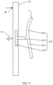
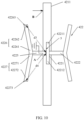
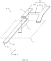
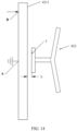
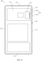
- FIG. 1 is a schematic view of a structure of an implementation of an electronic device 100 according to an embodiment of this application.
- the electronic device 100 may be a tablet computer, a mobile phone, a camera, a personal computer, a notebook computer, a vehicle-mounted device, a wearable device, augmented reality (augmented reality, AR) glasses, an AR helmet, virtual reality (virtual reality, VR) glasses, or a VR helmet.
- the electronic device 100 is described by using the mobile phone as an example.
- a width direction of the electronic device 100 is defined as an X axis
- a length direction of the electronic device 100 is a Y axis
- a thickness direction of the electronic device 100 is a Z axis.
- FIG. 2 is a schematic exploded view of the electronic device 100 shown in FIG. 1 .
- the electronic device 100 includes a housing 10, a screen 20, a circuit board 30, and an antenna 40.
- the screen 20 is mounted in the housing 10.
- An accommodating space 13 is enclosed by the screen 20 and the housing 10.
- the circuit board 30 is located in the accommodating space 13.
- the accommodating space 13 may alternatively be used to accommodate other components, such as a speaker, a microphone, an earpiece, and a camera module.
- the housing 10 includes a rear cover 11 and a bezel 12.
- the rear cover 11 is disposed opposite to the screen 20.
- the rear cover 11 is disposed on one side of the bezel 12 away from the screen 20.
- the accommodating space 13 is enclosed by the rear cover 11, the bezel 12, and the screen 30 together.
- FIG. 1 shows an approximately rectangular structure enclosed by the rear cover 11 and the bezel 12.
- the rear cover 11 is integrated with the bezel 12.
- the screen 20 includes a protection cover 21 and a display screen 22.
- the protection cover 21 is laminated on the display screen 22 to protect the display screen 22.
- the protection cover 21 may be made of a transparent material, for example, glass.
- the display screen 22 is used to display an image.
- the display screen 22 may be, but is not limited to, a liquid crystal display (liquid crystal display, LCD).
- the display screen 22 may alternatively be an organic light-emitting diode (organic light-emitting diode, OLED) display screen.
- the circuit board 30 is located between the screen 20 and the rear cover 11.
- Electronic components of the electronic device 100 are mounted on the circuit board 30.
- the electronic components may include a central processing unit (central processing unit, CPU), a battery management unit, and a baseband processing unit.
- the antenna 40 may be configured to receive and transmit signals.
- the antenna 40 includes a radio frequency transceiver circuit 41 and a radiator 42.
- the radio frequency transceiver circuit 41 may include a radio frequency transceiver chip having an independent module.
- the radio frequency transceiver chip is configured to transmit and receive radio frequency signals. It may be understood that the radio frequency transceiver chip having an independent module may be disposed to independently run functions of transmitting and receiving radio frequency signals, thereby improving signal transmission efficiency and further improving antenna performance.
- the radio frequency transceiver circuit 41 may further include a component such as a capacitor, an inductor, or a resistor. The capacitor, inductor, or resistor is used to assist in transmitting a radio frequency signal, for example, amplifying the radio frequency signal.
- the radio frequency transceiver circuit 41 may include a processing unit, for example, a CPU.
- the functions of transmitting and receiving radio frequency signals may be integrated into the CPU. It may be understood that, because the CPU has the functions of transmitting and receiving radio frequency signals, a space occupied by one chip may be saved inside the electronic device 100. Therefore, utilization of an internal space of the electronic device 100 is improved.
- the functions of transmitting and receiving radio frequency signals may alternatively be integrated on another chip, for example, a battery management chip.
- the radiator 42 is configured to radiate a signal outside of the electronic device 100 when receiving a radio frequency signal transmitted by the radio frequency transceiver circuit 41.
- the radiator 42 may be further configured to receive a signal outside of the electronic device 100, convert the received signal into a radio frequency signal, and transmit the radio frequency signal to the radio frequency transceiver circuit 41.
- the radiator 42 is disposed in a plurality of manners. The following describes in detail five embodiments of disposition manners of the radiator 42 with reference to the related drawings.
- the radiator 42 includes a first radiator 421 and a second radiator 422. Both the first radiator 421 and the second radiator 422 may be configured to radiate and receive signals. Specifically, when a radio frequency signal is coupled and fed to the second radiator 422 through the first radiator 421, each of the first radiator 421 and the second radiator 422 radiates a signal outside of the electronic device 100 based on the radio frequency signal. In addition, the second radiator 422 may also receive a signal outside of the electronic device 100, and convert the signal into a radio frequency signal. The radio frequency signal is coupled and fed to the first radiator 421 through the second radiator 422. The first radiator 421 may transmit the radio frequency signal to the radio frequency transceiver circuit 41.
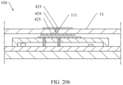
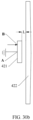
- FIG. 3a is a partial schematic cross-sectional view of an implementation of the electronic device 100 shown in FIG. 1 at a line M-M.
- the electronic device 100 further includes a support 50.
- the support 50 may be fixed to one side of the circuit board 30 away from the screen 20.
- the support 50 may have a frame structure.
- the support 50 covers the circuit board 30, and encloses a space S with the circuit board 30. Some electronic components on the circuit board 30 may be located in the space S. In this case, the support 50 may be configured to protect the electronic components.
- the support 50 may alternatively be plate-shaped or block-shaped.
- the support 50 has a first surface 55 facing the rear cover 11.
- the first radiator 421 is fixed to the first surface 55.
- a part of the support 50 forms an insulating portion, and the insulating portion is made of an insulating material.
- the first radiator 421 is formed on the insulating portion by using a laser directstructuring (laser directstructuring, LDS) technology.
- LDS laser directstructuring
- a conductive material for example, a metallic material such as gold, silver, or copper, or graphene
- the conductive material forms the first radiator 421.
- the support 50 may be completely made of an insulating material.
- FIG. 3b is a schematic view of a structure of the rear cover and the second radiator of the electronic device shown in FIG. 1 .
- the rear cover 11 may be made of an insulating material.
- the rear cover 11 has a second surface 115 facing the accommodating space 13.
- the second radiator 422 is fixed to the second surface 115.
- the second radiator 422 is formed on the second surface 115 of the rear cover 11 by using LDS.
- the rear cover 11 may alternatively include an insulating portion and a conductive portion connected to the insulating portion.
- the second radiator 422 is fixed to the insulating portion of the rear cover 11.
- a conductive material for example, a metallic material such as gold, silver, or copper, or graphene
- the conductive material forms the second radiator 422.
- the rear cover 11 has a surface away from the accommodating space 13.
- the second radiator 422 may alternatively be fixed to the surface of the rear cover 11 away from the accommodating space 13.
- the surface of the rear cover 11 away from the accommodating space 13 may be an exposed surface of the rear cover 11.
- the first radiator 421 is fixed to the first surface 55 of the support 50, and the second radiator 422 is fixed to the second surface 115, so that the second radiator 422 and the first radiator 421 are coupled to each other.
- the radio frequency transceiver circuit 41 transmits a radio frequency signal
- the radio frequency signal may be coupled and fed to the second radiator 422 through the first radiator 421.
- the second radiator 422 radiates a signal outside of the electronic device 100.
- the first radiator 421 and the second radiator 422 may generate a resonance mode: a convection mode, that is, a common mode.
- the first radiator 421 and the second radiator 422 may generate a plurality of resonance modes, such as a convection mode and a differential mode.
- the radiator 42 in this embodiment may generate a convection mode.
- SAR specific absorption rate
- the antenna 40 further includes a first spring 43 and a second spring 44. Both the first spring 43 and the second spring 44 may be fixed to the circuit board 30.
- the first spring 43 is configured to feed a radio frequency signal transmitted by the radio frequency transceiver circuit 41 into the first radiator 421.
- the second spring 44 is configured to ground the first radiator 421.
- a contact point between the first spring 43 and the first radiator 421 may be a feeding point B.
- a contact point between the second spring 44 and the first radiator 421 is a grounding point A.
- the feeding point B is not limited to a position shown in FIG. 3a described later.
- the feeding point B may alternatively be located at any position on the first radiator 421.
- a radio frequency signal transmitted by the radio frequency transceiver circuit 41 may alternatively be fed into the first radiator 421 by using a connector.
- the first radiator 421 may alternatively be grounded by using the connector.
- FIG. 4 is a schematic view of a partial structure of the electronic device 100 shown in FIG. 1 .
- FIG. 4 shows a position relationship between the second radiator 422 and the first radiator 421 on the support 50 when the rear cover 11 is removed from the electronic device 100.
- a position between the first radiator 421 and the second radiator 422 is not limited to the following: A part of the second radiator 422 is disposed opposite to the first radiator 421 shown in FIG. 4 , and a part of the second radiator 422 is not disposed opposite to the first radiator 421.
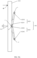
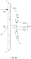
- FIG. 5a is a schematic view of a structure of an implementation of the radiator of the electronic device shown in FIG. 4 .
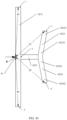
- FIG. 5b is a side view of the radiator shown in FIG. 5a .
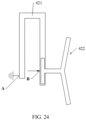
- the first radiator 421 includes a first feeding branch 4211.
- the first feeding branch 4211 is strip-shaped.
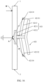
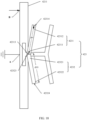
- the second radiator 422 includes a first branch 4221, a second branch 4222, and a third branch 4911.
- the first branch 4221 includes a head end 42211 and a tail end 42212.
- the third branch 4911 includes a head end 49111 and a tail end 49112.
- One end of the second branch 4222 is connected between the head end 42211 and the tail end 42212 of the first branch 4221, and the other end of the second branch 4222 is connected between the head end 49111 and the tail end 49112 of the third branch 4911.
- the head end 42211 and the tail end 42212 of the first branch 4221 are located on two sides of the second branch 4222.
- the head end 49111 and the tail end 49112 of the third branch 4911 are located on the two sides of the second branch 4222. It may be understood that the two sides of the second branch 4222 may be understood as two sides of the second branch 4222 itself, or may be understood as two sides in an extension direction of the second branch 4222.
- first branch 4221 is spaced apart from and disposed opposite to the first feeding branch 4211.
- One part of the second branch 4222 is spaced apart from and disposed opposite to the first feeding branch 4211.
- Another part of the second branch 4222 is spaced apart from but not disposed opposite to the first feeding branch 4211.
- the third branch 4911 is spaced apart from but not disposed opposite to the first feeding branch 4211.
- the first branch 4221 has a reference face 5 away from the second branch 4222.
- a projection of the reference face 5 on a plane P in which the first feeding branch 4211 is located is a first projection b.
- FIG. 5a shows the first projection b as a line.
- the first projection b is located in the first feeding branch 4211.
- the reference face 5 may alternatively be an arc surface, and the first projection b may be an arc or an area.
- FIG. 5c is a top view of the radiator 42 shown in FIG. 5a .
- the first feeding branch 4211 includes a first end face 1 and a second end face 2 disposed away from the first end face 1.
- a distance from a center of the first end face 1 to the grounding point A is a fifth value d5.
- a distance from a center of the second end face 2 to the grounding point A is a sixth value d6.
- a ratio of the fifth value d5 to the sixth value d6 is within a range of 0.3 to 3.
- the first feeding branch 4211 has a quasi-symmetrical or symmetrical structure.
- the ratio of the fifth value d5 to the sixth value d6 is 1.
- the ratio of the fifth value d5 to the sixth value d6 may alternatively be 0.3, 0.8, 1.2, 2.3, or 2.9.
- FIG. 6 is a graph of a relationship between a reflection coefficient (that is, a return loss) and a frequency of the radiator 42 shown in FIG. 5a in a frequency band of 0 to 6 GHz.
- the radio frequency transceiver circuit 41 transmits radio frequency signals in the frequency band of 0 to 6 GHz
- the radio frequency signals are transmitted to the first radiator 421 and the second radiator 422.
- the first radiator 421 and the second radiator 422 may generate two resonance frequencies from 0 to 6 GHz.
- FIG. 6 shows that the two resonance frequencies generated by the first radiator 421 and the second radiator 422 are f1 and f2 respectively. It may be understood that this implementation is described by using the frequency band of 0 to 6 GHz as an example.
- the radio frequency transceiver circuit 41 transmits radio frequency signals in the frequency band of 0 to 6 GHz
- the radio frequency signals are transmitted to the first radiator 421 and the second radiator 422.
- the first feeding branch 4211 has a first current flowing from the first end face 1 to the grounding point A and a second current flowing in a direction from the second end face 2 to the grounding point A.
- FIG. 7 shows the first current and the second current by using solid lines with arrows.
- the second radiator 422 when the second radiator 422 is disposed close to the first feeding branch 4211, a strong coupling can be implemented between the first feeding branch 4211 and the second radiator 422.
- the second radiator 422 has a quasi-symmetrical or symmetrical structure, the second radiator 422 has a third current flowing from the end face 3 of the tail end of the first bifurcation branch 4223 to the second branch 4222, and a fourth current flowing in a direction from the end face 4 of the tail end of the second bifurcation branch 4224 to the second branch 4222.
- FIG. 7 shows the third current and the fourth current by using dashed lines with arrows.
- the frequency f1 is a resonance frequency of the convection mode, that is, the first resonance frequency f1 shown in FIG. 6 .
- the resonance frequency f1 is mainly the resonance frequency generated by the first feeding branch 4211.
- the radio frequency transceiver circuit 41 transmits radio frequency signals in the frequency band of 0 to 6 GHz
- the radio frequency signals are transmitted to the first radiator 421 and the second radiator 422.
- the first feeding branch 4211 has a first current flowing from the first end face 1 to the grounding point A and a second current flowing in a direction from the second end face 2 to the grounding point A.
- FIG. 7 shows the first current and the second current by using solid lines with arrows.
- the second radiator 422 when the second radiator 422 is disposed close to the first radiator 421, a strong coupling can be implemented between the first feeding branch 4211 and the second radiator 422.
- the second radiator 422 has a quasi-symmetrical or symmetrical structure, the second radiator 422 has a third current flowing from the head end 42211 of the first branch 4221 to the end face 3 of the tail end of the first bifurcation branch 4223, and a fourth current flowing from the tail end 42212 of the first branch 4221 to the end face 4 of the tail end of the second bifurcation branch 4224.
- FIG. 8 shows the third current and the fourth current by using dashed lines with arrows.
- a resonance mode generated by the first feeding branch 4211 and the second radiator 422 at the frequency f2 is a convection mode.
- the frequency f2 is a resonance frequency of the convection mode, that is, the first resonance frequency f2 shown in FIG. 6 .
- the resonance frequency f2 is mainly the resonance frequency generated by the second radiator 422.
- the two resonance frequencies shown in FIG. 6 are both resonance frequencies of convection modes.
- the first radiator 421 and the second radiator 422 in this implementation can generate two convection modes.
- the first radiator 421 and the second radiator 422 when the first radiator 421 and the second radiator 422 receive the radio frequency signals in the frequency band of 0 to 6 GHz, the first radiator 421 and the second radiator 422 can generate resonance frequencies of two convection modes in the frequency band.
- An operating frequency band of the antenna 40 is set near the resonance frequency of the convection mode. In this way, when the first radiator 421 and the second radiator 422 radiate signals, the signals have little adverse impact on the user.
- a resonance mode with a low specific absorption rate covers a relatively wide frequency band in the frequency band of 0 to 6 GHz. In other words, there are more convection modes, and the operating frequency band set near the resonance frequency is also wider.
- the two resonance frequencies f1 and f2 generated by the first radiator 421 and the second radiator 422 may be any value from 0 to 6 GHz.
- f1 may be 4 GHz
- f2 may be 4.6 GHz.
- values of the two resonance frequencies f1 and f2 are related to a factor such as a length of the first feeding branch 4211, a length of the second branch 4222, a length of the first branch 4211, a length of the first bifurcation branch 4223, a length of the second bifurcation branch 4224, a position of the feeding point B, or an external environment in which the first radiator 421 and the second radiator 422 are located (for example, fixed positions of the first radiator 421 and the second radiator 422).
- the values of f1 and f2 may be changed.
- the first resonance frequency f1 may be changed from 4 GHz to 4.1 GHz.
- the second resonance frequency is changed from 4.6 GHz to 4.5 GHz.
- the first radiator 421 and the second radiator 422 may generate a differential mode, by changing the factor such as the length of the first feeding branch 4211, the length of the second branch 4222, the length of the first branch 4211, the length of the first bifurcation branch 4223, the length of the second bifurcation branch 4224, the ratio of the fifth value d5 to the sixth value d6, the ratio of the first value d1 to the second value d2, the position of the feeding point B, or the external environment in which the first radiator 421 and the second radiator 422 are located, a resonance frequency of the differential mode may also be changed correspondingly.
- FIG. 9 is a schematic view of a structure of another implementation of the radiator 42 according to an embodiment of this application.
- the first bifurcation branch 4223 is arc-shaped.
- the second bifurcation branch 4224 is strip-shaped.
- the first branch 4221, the second branch 4222, the first bifurcation branch 4223, and the second bifurcation branch 4224 are approximately I-shaped.
- the first feeding branch 4211 and the second radiator 422 can also generate two convection modes.
- a principle of generating two convection modes by the first feeding branch 4211 and the second radiator 422 is the same as a principle of generating two convection modes in the first implementation, and details are not described herein again.
- the shape of the first bifurcation branch 4223 and the shape of the second bifurcation branch 4224 may alternatively be interchanged.
- FIG. 10 is a schematic view of a structure of another implementation of the radiator according to an embodiment of this application.
- the second radiator 422 further includes a fourth branch 4225, a third bifurcation branch 4226, and a fourth bifurcation branch 4227.
- the fourth branch 4225, the third bifurcation branch 4226, and the fourth bifurcation branch 4227 are located on one side of the first branch 4221 away from the second branch 4222.
- a head end 42261 of the third bifurcation branch 4226 is connected to a head end 42271 of the fourth bifurcation branch 4227.
- one end of the fourth branch 4225 is connected to the head end 42261 of the third bifurcation branch 4226 and the head end 42271 of the fourth bifurcation branch 4227, and the other end of the fourth branch 4225 is connected to the reference face 5.
- a tail end 42262 of the third bifurcation branch 4226 and a tail end 42272 of the fourth bifurcation branch 4227 are located on two sides of the fourth branch 4225.
- the third bifurcation branch 4226 extends in a direction away from the reference face 5.
- the fourth bifurcation branch 4227 extends in a direction away from the reference face 5.
- the second radiator 422 is back-to-back E-shaped, or is approximately back-to-back E-shaped.
- the two sides of the fourth branch 4225 may be understood as two sides of the fourth branch 4225 itself, or may be understood as two sides in an extension direction of the fourth branch 4225.
- the third bifurcation branch 4226 and the fourth bifurcation branch 4227 are strip-shaped.
- An included angle between the third bifurcation branch 4226 and the fourth bifurcation branch 4227 is also the same as the included angle a between the first bifurcation branch 4223 and the second bifurcation branch 4224 in the first implementation.
- a center distance between an end face 42263 of the tail end of the third bifurcation branch 4226 and the reference face 5 is a third value d3.
- a center distance between an end face 42273 of the tail end of the fourth bifurcation branch 4227 and the reference face 5 is a fourth value d4.
- a ratio of the third value d3 to the fourth value d4 may be within a range of 0.5 to 2.
- the second radiator 422 still has a quasi-symmetrical or symmetrical structure.
- the ratio of the third value d3 to the fourth value d4 is 1.
- the ratio of the third value d3 to the fourth value d4 may alternatively be 0.8, 1.22, 1.5, or 2.
- FIG. 11 is a graph of a relationship between a reflection coefficient and a frequency of the radiator 42 shown in FIG. 10 in the frequency band of 0 to 6 GHz.
- the radio frequency transceiver circuit 41 transmits radio frequency signals in the frequency band of 0 to 6 GHz
- the radio frequency signals are transmitted to the first radiator 421 and the second radiator 422.
- the first feeding branch 4211 and the second radiator 422 generate three resonance frequencies in the frequency band.
- FIG. 11 shows that the three resonance frequencies generated by the first feeding branch 4211 and the second radiator 422 are f1, f2, and f3 respectively.
- the third resonance frequency f3 is mainly generated by the third bifurcation branch 4226 and the fourth bifurcation branch 4227.
- the radio frequency transceiver circuit 41 transmits radio frequency signals in the frequency band of 0 to 6 GHz
- the radio frequency signals are transmitted to the first radiator 421 and the second radiator 422.
- the second radiator 422 has a current flowing from the head end 42211 of the first branch 4221 to the end face 42263 of the tail end of the third bifurcation branch 4226, and a current flowing from the tail end 42212 of the first branch 4221 to the end face 42273 of the tail end of the fourth bifurcation branch 4227.
- a resonance mode generated by the third bifurcation branch 4226 and the fourth bifurcation branch 4227 is a convection mode.
- the frequency f3 is a resonance frequency of the convection mode, that is, the third resonance frequency f3 shown in FIG. 11 .
- the three resonance frequencies f1, f2, and f3 generated by the first radiator 421 and the second radiator 422 may be any value from 0 to 6 GHz.
- f1, f2, and f3 are 4 GHz, 4.6 GHz, and 5 GHz respectively.
- the third resonance frequency f3 is also changed.
- the third resonance frequency f3 may be changed from 5 GHz to 5.1 GHz.
- the fourth branch 4225, the third bifurcation branch 4226, and the fourth bifurcation branch 4227 are connected to one side of the first branch 4221 away from the second branch 4222. Therefore, a third convection mode is generated by using the third bifurcation branch 4226 and the fourth bifurcation branch 4227, that is, a quantity of convection modes generated by the first radiator 421 and the second radiator 422 is increased to three.
- a resonance mode with a low specific absorption rate covers a relatively wide frequency band in the frequency band of 0 to 6 GHz. Therefore, the operating frequency band of the antenna is wider.
- the operating frequency band of the antenna may be resonance frequencies corresponding to the three convection modes. For example, the operating frequency band is 3.8 GHz to 4.2 GHz, 4.4 GHz to 4.8 GHz, and 4.8 GHz to 5.2 GHz.
- FIG. 12 is a schematic view of a structure of still another implementation of the radiator 42 according to an embodiment of this application.
- the second radiator 422 further includes a fourth branch 4225, a third bifurcation branch 4226, and a fourth bifurcation branch 4227.
- the fourth branch 4225, the third bifurcation branch 4226, and the fourth bifurcation branch 4227 are all located on one side of the first bifurcation branch 4223 and the second bifurcation branch 4224 away from the second branch 4222.
- a head end 42261 of the third bifurcation branch 4226 is connected to a head end 42271 of the fourth bifurcation branch 4227.
- One end of the fourth branch 4225 is connected to the head end 42261 of the third bifurcation branch 4226 and the head end 42271 of the fourth bifurcation branch 4227, and the other end of the fourth branch 4225 is connected to the head end 42231 of the first bifurcation branch 4223 and the head end 42241 of the second bifurcation branch 4224.
- a tail end 42262 of the third bifurcation branch 4226 and a tail end 42272 of the fourth bifurcation branch 4227 are located on two sides of the fourth branch 4225.
- the third bifurcation branch 4226 extends in a direction away from the reference face 5.
- the fourth bifurcation branch 4227 extends in a direction away from the reference face 5.
- the second radiator 422 is back-to-back E-shaped, or is approximately back-to-back E-shaped.
- the two sides of the fourth branch 4225 may be understood as two sides of the fourth branch 4225 itself, or may be understood as two sides in an extension direction of the fourth branch 4225.
- the third bifurcation branch 4226 and the fourth bifurcation branch 4227 are strip-shaped.
- An included angle between the third bifurcation branch 4226 and the fourth bifurcation branch 4227 is also the same as the included angle a between the first bifurcation branch 4223 and the second bifurcation branch 4224 in the first implementation.
- a center distance between an end face 42263 of the tail end of the third bifurcation branch 4226 and the reference face 5 is a third value d3.
- a center distance between an end face 42273 of the tail end of the fourth bifurcation branch 4227 and the reference face 5 is a fourth value d4.
- a ratio of the third value d3 to the fourth value d4 is within a range of 0.5 to 2.
- the second radiator 422 still has a quasi-symmetrical or symmetrical structure.
- the ratio of the third value d3 to the fourth value d4 is 1.
- the ratio of the third value d3 to the fourth value d4 may alternatively be 0.8, 1.22, 1.5, or 2.
- the radio frequency transceiver circuit 41 transmits radio frequency signals in the frequency band of 0 to 6 GHz
- the radio frequency signals are transmitted to the first radiator 421 and the second radiator 422.
- the second radiator 422 has a current flowing from the fourth branch 4225 to the end face 42263 of the tail end of the third bifurcation branch 4226, and a current flowing from the fourth branch 4225 to the end face 42273 of the tail end of the fourth bifurcation branch 4227. It can be determined based on current distribution on the third bifurcation branch 4226 and the fourth bifurcation branch 4227 that a resonance mode generated by the third bifurcation branch 4226 and the fourth bifurcation branch 4227 is a convection mode.
- the frequency f3 is a resonance frequency of the convection mode.
- the three resonance frequencies f1, f2, and f3 generated by the first radiator 421 and the second radiator 422 may be any value from 0 to 6 GHz.
- f1, f2, and f3 are 4 GHz, 4.6 GHz, and 5 GHz respectively.
- the third resonance frequency f3 is also changed.
- the third resonance frequency f3 may be changed from 5 GHz to 5.1 GHz.
- the fourth branch 4225, the third bifurcation branch 4226, and the fourth bifurcation branch 4227 are connected to one side of the first bifurcation branch 4223 and the second bifurcation branch 4224 away from the second branch 4222. Therefore, a third convection mode is generated by using the current on the third bifurcation branch 4226 and the fourth bifurcation branch 4227, that is, a quantity of convection modes generated by the first radiator 421 and the second radiator 422 is increased to three.
- a resonance mode with a low specific absorption rate covers a relatively wide frequency band in the frequency band of 0 to 6 GHz. Therefore, the operating frequency band of the antenna is wider.
- the operating frequency band of the antenna may be resonance frequencies of the three convection modes.
- the operating frequency band is 3.8 GHz to 4.2 GHz, 4.4 GHz to 4.8 GHz, and 4.8 GHz to 5.2 GHz.
- FIG. 14 is a schematic top view of the radiator shown in FIG. 13 .
- a shortest distance L between the first feeding branch 4211 and the first projection b of the reference face 5 on the plane in which the first feeding branch 4211 is located is within a range of 0 to 3 millimeters.
- the first feeding branch 4211 is disposed close to the second radiator 422.
- the shortest distance L in this implementation is 1 millimeter.
- the shortest distance L may be 0 millimeters, 0.2 millimeter, 0.75 millimeter, 1.3 millimeters, or 2.6 millimeters.
- FIG. 15 is a graph of a relationship between a reflection coefficient and a frequency of the radiator 42 shown in FIG. 14 in the frequency band of 0 to 6 GHz.
- the first radiator 421 and the second radiator 422 When radio frequency signals at a frequency of 0 to 6 GHz are fed to the first radiator 421 and the second radiator 422, the first radiator 421 and the second radiator 422 generate two resonance modes in the frequency band, that is, the first radiator 421 and the second radiator 422 may generate two resonance frequencies in the frequency band.
- FIG. 15 shows that the two resonance frequencies generated by the first radiator 421 and the second radiator 422 are f1 and f2 respectively. It may be understood that a principle of forming the two convection modes in this implementation is the same as a principle of forming the first convection mode and the second convection mode in the first implementation. Details are not described herein.
- the two resonance frequencies f1 and f2 generated by the first radiator 421 and the second radiator 422 may be any value from 0 to 6 GHz.
- f1 may be 4 GHz
- f2 may be 4.6 GHz.
- the two resonance frequencies f1 and f2 generated by the first radiator 421 and the second radiator 422 are also changed, that is, the two resonance frequencies f1 and f2 may be other values.
- the second resonance frequency f2 generated by the first radiator 421 and the second radiator 422 is changed from 4.6 GHz to 4.7 GHz.
- the first radiator 421 and the second radiator 422 when the first radiator 421 and the second radiator 422 receive the radio frequency signals in the frequency band of 0 to 6 GHz, the first radiator 421 and the second radiator 422 can generate a convection mode in the frequency band.
- the operating frequency band of the antenna 40 may be set around a resonance frequency of the convection mode, so that when the first radiator 421 and the second radiator 422 radiate signals, the signals radiated by the first radiator 421 and the second radiator 422 have little adverse impact on the user.
- the structure of the second radiator 422 is not limited to the structure shown in FIG. 13 and FIG. 14 .
- the structure of the second radiator 422 may alternatively be any structure in the first implementation to the third implementation. A specific structure is not limited in this implementation.
- connection branch 4212 may be understood as two sides of the connection branch 4212 itself, or may be understood as two sides in an extension direction of the connection branch 4212.
- the first feeding branch 4211, the connection branch 4212, and the second feeding branch 4213 are all strip-shaped.
- the first radiator 421 is I-shaped or is approximately I-shaped.
- shapes of the connection branch 4212 and the second feeding branch 4213 may alternatively be other shapes.
- the second feeding branch 4213 is arc-shaped. This is not specifically limited in this application.
- a distance between a center of an end face 42133 of the first tail end 42131 and the grounding point A is a seventh value d7.
- a distance between a center of an end face 42134 of the second tail end 42132 and the grounding point A is an eighth value d8.
- a ratio of the seventh value d7 to the eighth value d8 is within a range of 0.3 to 3. In this implementation, the ratio of the seventh value d7 to the eighth value d8 is 1. In another implementation, the ratio of the seventh value d7 to the eighth value d8 may alternatively be 0.5, 0.6, 2, or 2.5.
- the radio frequency transceiver circuit 41 transmits radio frequency signals in the frequency band of 0 to 6 GHz
- the radio frequency signals are transmitted to the first radiator 421 and the second radiator 422.
- the first radiator 421 and the second radiator 422 generate three resonance frequencies in the frequency band, and the three resonance frequencies are f1, f2, and f3 respectively.
- the three resonance modes are also all convection modes.
- a principle of forming the first resonance frequency f1 and the second resonance frequency f2 is the same as a principle of forming the first resonance frequency f1 and the second resonance frequency f2 in the first implementation. Details are not described herein.
- the third resonance frequency f3 is mainly generated by the second feeding branch 4213.
- the radio frequency transceiver circuit 41 transmits radio frequency signals in the frequency band of 0 to 6 GHz
- the radio frequency signals are transmitted to the first radiator 421 and the second radiator 422.
- the second feeding branch 4213 has a current flowing from the connection branch 4212 to the two end faces of the second feeding branch 4213. It can be determined based on current distribution on the second feeding branch 4213 that a resonance mode generated by the second feeding branch 4213 is a convection mode.
- the frequency f3 is a resonance frequency of the convection mode.
- the third resonance frequency f3 generated by the second feeding branch 4213 may be any value in the frequency band of 0 to 6 GHz.
- f3 is 5 GHz.
- the resonance frequency f3 of the third convection mode is also changed, that is, the resonance frequency of the third convection mode may alternatively be another value.
- connection branch 4212 and the second feeding branch 4213 are disposed on one side of the first feeding branch 4211, so that the third convection mode is generated by using the current on the connection branch 4212 and the current on the second feeding branch 4213, that is, a quantity of convection modes generated by the first radiator 421 and the second radiator 422 is increased to three.
- a resonance mode with a low specific absorption rate covers a relatively wide frequency band in the frequency band of 0 to 6 GHz. Therefore, the operating frequency band of the antenna is wider.
- the operating frequency band of the antenna may be a set surrounding frequency band in which the resonance frequencies of the three convection modes are located.
- the structure of the second radiator 422 is not limited to the structure shown in FIG. 16 .
- the structure of the second radiator 422 may alternatively be any structure in the second implementation and the third implementation. Details are not described herein again.
- FIG. 17 is a schematic cross-sectional view of another implementation of the electronic device 100 shown in FIG. 1 at the line M-M.
- the radiator 42 further includes a third radiator 423.
- the third radiator 423 is located on one side of the second radiator 422 away from the first radiator 421.
- the third radiator 423 is formed on the surface of the rear cover 11 away from the accommodating space 13 by using LDS, that is, the third radiator 423 is formed on an outer surface of the rear cover 11.
- the first radiator 421 is formed on the first surface 55 of the support 50.
- the second radiator 422 is formed on the second surface 115 of the rear cover 11.
- the first radiator 421, the second radiator 422, and the third radiator 423 are located at different layers.
- the third radiator 423 may alternatively be formed in another manner.
- a conductive material for example, a metallic material such as gold, silver, or copper, or graphene
- the conductive material forms the third radiator 423.
- FIG. 18 is a schematic view of a structure of the radiator 42 of the electronic device 100 shown in FIG. 17 .
- the third radiator 423 includes a fifth bifurcation branch 4231 and a sixth bifurcation branch 4232.
- a head end 42311 of the fifth bifurcation branch 4231 and a head end 42321 of the sixth bifurcation branch 4232 are connected to each other.
- the fifth bifurcation branch 4231 extends in a direction away from the head end 42321 of the sixth bifurcation branch 4232.
- the sixth bifurcation branch 4232 extends in a direction away from the head end 42311 of the fifth bifurcation branch 4231.
- a projection of the third radiator 423 on the first radiator 421 is partly located in the first radiator 421.
- the projection of the third radiator 423 on the first radiator 421 may be completely located in the first radiator 421.
- a center distance between an end face 42313 of the head end and an end face 42314 of a tail end of the fifth bifurcation branch 4231 is a ninth value d9.
- a center distance between an end face 42323 of the head end and an end face 42324 of a tail end of the sixth bifurcation branch 4232 is a tenth value d10.
- a ratio of the ninth value d9 to the tenth value d10 is within a range of 0.5 to 2.
- the third radiator 423 has a quasi-symmetrical or symmetrical structure.
- the ratio of the ninth value d9 to the tenth value d10 is 1.
- the ratio of the ninth value d9 to the tenth value d10 may alternatively be 0.8, 1.22, 1.5, or 2.
- FIG. 19 is a graph of a relationship between a reflection coefficient and a frequency of the radiator 42 shown in FIG. 18 in the frequency band of 0 to 6 GHz.
- the radio frequency transceiver circuit 41 transmits radio frequency signals in the frequency band of 0 to 6 GHz
- the radio frequency signals are transmitted to the first feeding branch 4211, the second radiator 422, and the third radiator 423.
- the first feeding branch 4211, the second radiator 422, and the third radiator 423 generate three resonance frequencies in the frequency band.
- FIG. 19 shows that the three resonance frequencies generated by the first feeding branch 4211, the second radiator 422, and the third radiator 423 are f1, f2 and f3 respectively.
- the third resonance frequency f3 is mainly a resonance mode generated by the third radiator 423.
- the radio frequency transceiver circuit 41 transmits radio frequency signals in the frequency band of 0 to 6 GHz
- the radio frequency signals are transmitted to the first feeding branch 4211, the second radiator 422, and the third radiator 423.
- the third radiator 423 has a current flowing from the head end 42311 to the tail end 42312 of the fifth bifurcation branch 4231, and a current flowing from the head end 42321 to the tail end 42322 of the sixth bifurcation branch 4232. It can be determined based on current distribution on the third radiator 423 that a resonance mode generated by the third radiator 423 is a convection mode.
- the frequency f3 is a resonance frequency of the convection mode, that is, the third resonance frequency f3 shown in FIG. 19 .
- the three resonance frequencies f1, f2, and f3 generated by the first feeding branch 4211, the second radiator 422, and the third radiator 423 may be any value from 0 to 6 GHz.
- f1, f2, and f3 are 4 GHz, 4.6 GHz, and 5 GHz respectively.
- the third resonance frequency f3 is also changed.
- the third resonance frequency f3 may be changed from 5 GHz to 5.1 GHz.
- the third radiator 423 is disposed on one side of the second radiator 422 away from the first radiator 421, a third convection mode is generated by using a current on the third radiator 423, that is, a quantity of convection modes generated by the first radiator 421, the second radiator 422, and the third radiator 423 is increased to three.
- a resonance mode with a low specific absorption rate covers a relatively wide frequency band in the frequency band of 0 to 6 GHz. Therefore, the operating frequency band of the antenna is wider.
- the operating frequency band of the antenna may be a surrounding frequency band in which the resonance frequencies of the three convection modes are located.
- the operating frequency band is 3.8 GHz to 4.2 GHz, 4.4 GHz to 4.8 GHz, and 4.8 GHz to 5.2 GHz.
- the structure of the first radiator 421 is not limited to the structure shown in FIG. 18 .
- the structure of the first radiator 421 may alternatively be the structure of the first radiator 421 in the fifth implementation.
- the structure of the second radiator 422 is not limited to the structure shown in FIG. 18 .
- the structure of the second radiator 422 may alternatively be any structure in the second implementation and the third implementation. A specific structure is not limited in this implementation.
- the third radiator 423 may alternatively be a multi-branch structure.
- the third radiator 423 is I-shaped or back-to-back E-shaped.
- FIG. 20a is a schematic view of a structure of still another implementation of the radiator 42 according to an embodiment of this application.
- a shortest distance L between the first radiator 421 and the projection of the third radiator 423 on the first radiator 421 is within a range of 0 to 3 millimeters.
- L may be 0 millimeters, 0.2 millimeter, 0.75 millimeter, 1.3 millimeters, or 2.6 millimeters.
- the first radiator 421, the second radiator 422, and the third radiator 423 can also generate three convection modes. It may be understood that a principle of forming the three convection modes in this implementation is the same as a principle of forming the three convection modes in the sixth implementation. Details are not described herein.
- FIG. 20b is a schematic cross-sectional view of still another implementation of the electronic device 100 shown in FIG. 1 at the line M-M.
- the radiator 42 may further include a fourth connection branch 424.
- the fourth connection branch 424 is connected between the third radiator 423 and the second radiator 422.
- a through hole 111 may be opened in the rear cover 11.
- the through hole 111 penetrates an inner surface and the outer surface of the rear cover 11.
- the fourth connection branch 424 is located in the through hole 111. In this case, because the third radiator 423 is formed on the outer surface of the rear cover 11 and the second radiator 422 is formed on the inner surface of the rear cover 11, the fourth connection branch 424 can connect the third radiator 423 to the second radiator 422.
- FIG. 21 is a schematic view of a structure of still another implementation of the radiator 42 according to an embodiment of this application.
- the first radiator 421 has a feeding point B, but does not have a grounding point A.
- Definitions of a fifth value d5 and a sixth value d6 in this implementation are different from definitions of the fifth value d5 and the sixth value d6 in the first implementation.
- a distance between a center of a first end face 1 and the feeding point B of the first feeding branch 4211 is a fifth value d5.
- a distance between a center of a second end face 2 and the feeding point B is a sixth value d6.
- a ratio of the fifth value d5 to the sixth value d6 is within a range of 0.3 to 3.
- the first radiator 421 has a quasi-symmetrical or symmetrical structure.
- the ratio of the fifth value d5 to the sixth value d6 is 1.
- the ratio of the fifth value d5 to the sixth value d6 may alternatively be 0.3, 0.8, 1.2, 2.3, or 2.9.
- the first feeding branch 4211 and the second radiator 422 when radio frequency signals at a frequency of 0 to 6 GHz are fed to the first feeding branch 4211 and the second radiator 422, the first feeding branch 4211 and the second radiator 422 generate two resonance modes in the frequency band, that is, the first feeding branch 4211 and the second radiator 422 may generate two resonance frequencies in the frequency band, and the two resonance frequencies are f1 and f2 respectively.
- the first feeding branch 4211 has a first current flowing from the first end face 1 to the feeding point B and a second current flowing in a direction from the second end face 2 to the feeding point B.
- current distribution on the second radiator 422 is the same as current distribution on the second radiator 422 in the first implementation. Therefore, it can be determined based on current distribution on the first feeding branch 4211 and the second radiator 422 that a resonance mode generated by the first feeding branch 4211 and the second radiator 422 at the frequency f1 is a convection mode.
- the frequency f1 is a resonance frequency of the convection mode.
- the first feeding branch 4211 has a first current flowing from the first end face 1 to the feeding point B and a second current flowing in a direction from the second end face 2 to the feeding point B.
- current distribution on the second radiator 422 is the same as current distribution on the second radiator 422 in the first implementation. Therefore, it can be determined based on current distribution on the first feeding branch 4211 and the second radiator 422 that a resonance mode generated by the first feeding branch 4211 and the second radiator 422 at the frequency f2 is a convection mode.
- the frequency f2 is a resonance frequency of the convection mode.
- the structure of the first radiator 421 is not limited to the structure shown in FIG. 21 .
- the structure of the first radiator 421 may alternatively be the structure of the first radiator 421 in the fifth implementation.
- the structure of the second radiator 422 is not limited to the structure shown in FIG. 21 .
- the structure of the second radiator 422 may alternatively be any structure in the second implementation and the third implementation. Details are not described herein again.
- the radiator 42 may alternatively include a third radiator 423.
- For a manner of disposing the third radiator 423 refer to the sixth implementation. Details are not described herein again.
- for a position relationship between the first radiator 421 and the second radiator 422 refer to the fourth implementation. Details are not described herein again.
- FIG. 22 is a schematic view of a structure of still another implementation of the radiator 42 according to an embodiment of this application.
- the first radiator 421 may be an inverted-F antenna (Inverted-F Antenna, IFA), or may be a composite left/right-handed antenna (composite right/left-handed antenna, CRLH).
- IFA Inverted-F Antenna
- CRLH composite left/right-handed antenna
- FIG. 23 is a graph of a relationship between a reflection coefficient and a frequency of the radiator 42 shown in FIG. 22 in the frequency band of 0 to 6 GHz.
- the radio frequency transceiver circuit 41 transmits radio frequency signals in the frequency band of 0 to 6 GHz
- the radio frequency signals are transmitted to the first radiator 421 and the second radiator 422.
- the first radiator 421 and the second radiator 422 generate three resonance modes in the frequency band, that is, the first radiator 421 and the second radiator 422 may generate three resonance frequencies in the frequency band.
- FIG. 23 shows that the resonance frequencies generated by the first radiator 421 and the second radiator 422 are f1, f2, and f3 respectively.
- the first resonance mode may be a quarter mode
- the second resonance mode is a convection mode
- the third resonance mode is a differential mode
- the first radiator 421 and the second radiator 422 when the first radiator 421 and the second radiator 422 receive the radio frequency signals in the frequency band of 0 to 6 GHz, the first radiator 421 and the second radiator 422 can generate a convection mode in the frequency band.
- the operating frequency band of the antenna 40 may be set around a resonance frequency of the convection mode, so that when the first radiator 421 and the second radiator 422 radiate signals, the signals radiated by the first radiator 421 and the second radiator 422 have little adverse impact on the user.
- the structure of the second radiator 422 is not limited to the structure shown in FIG. 22 .
- the structure of the second radiator 422 may alternatively be any structure in the second implementation and the third implementation. Details are not described herein again.
- the position relationship between the first radiator 421 and the second radiator 422 may alternatively be the position shown in the fourth implementation.
- the radiator 42 may alternatively include a third radiator 423. For a manner of disposing the third radiator 423, refer to the sixth implementation. Details are not described herein again.
- FIG. 24 is a schematic view of a structure of still another implementation of the radiator 42 according to an embodiment of this application.
- the first radiator 421 is a loop antenna (loop antenna).
- the first radiator 421 is U-shaped, or is approximately U-shaped.
- the radio frequency transceiver circuit 41 transmits radio frequency signals in the frequency band of 0 to 6 GHz
- the radio frequency signals are transmitted to the first radiator 421 and the second radiator 422.
- the first radiator 421 and the second radiator 422 generate three resonance modes in the frequency band, that is, the first radiator 421 and the second radiator 422 may generate three resonance frequencies f1, f2, and f3 respectively in the frequency band.
- the first resonance mode may be a quarter mode
- the second resonance mode is a convection mode
- the third resonance mode is a differential mode.
- the first radiator 421 and the second radiator 422 when the first radiator 421 and the second radiator 422 receive the radio frequency signals in the frequency band of 0 to 6 GHz, the first radiator 421 and the second radiator 422 can generate a convection mode in the frequency band.
- the operating frequency band of the antenna 40 may be set around a resonance frequency of the convection mode, so that when the first radiator 421 and the second radiator 422 radiate signals, the signals radiated by the first radiator 421 and the second radiator 422 have little adverse impact on the user.
- a position of the second radiator 422 is not limited to one end portion of the first radiator 421 shown in FIG. 24 .
- a position of the second radiator 422 may be any position facing the first radiator 421.
- the structure of the second radiator 422 is not limited to the structure shown in FIG. 24 .
- the structure of the second radiator 422 may alternatively be any structure in the second implementation and the third implementation. Details are not described herein again.
- the position relationship between the first radiator 421 and the second radiator 422 may alternatively be the position shown in the fourth implementation.
- the radiator 42 may alternatively include a third radiator 423. For a manner of disposing the third radiator 423, refer to the sixth implementation. Details are not described herein again.
- FIG. 25a is a schematic view of a structure of still another implementation of the radiator 42 according to an embodiment of this application.
- the second radiator 422 includes a first branch 4221, a first bifurcation branch 4223, and a second bifurcation branch 4224.
- a head end 42231 of the first bifurcation branch 4223 and a head end 42241 of the second bifurcation branch 4224 are connected to the first branch 4221.
- a tail end 42232 of the first bifurcation branch 4223 and a tail end 42242 of the second bifurcation branch 4224 are located on two sides of the first branch 4221.
- the second radiator 422 is Y-shaped, or is approximately T-shaped.
- the two sides of the first branch 4221 may be understood as two sides of the first branch 4221 itself, or may be understood as two sides in an extension direction of the first branch 4221.
- first branch 4221 has a reference face 5 away from the first bifurcation branch 4223 and the second bifurcation branch 4224.
- a projection of the reference face 5 on the first feeding branch 4211 partly overlaps the first feeding branch 4211.
- a projection of the reference face 5 on the first feeding branch 4211 may completely overlap the first feeding branch 4211.
- a center distance between an end face 3 of the tail end of the first bifurcation branch 4223 and the reference face 5 is a first value d1.
- a center distance between an end face 4 of the tail end of the second bifurcation branch 4224 and the reference face 5 is a second value d2.
- a ratio of the first value d1 to the second value d2 is within a range of 0.5 to 2.
- the second radiator 422 has a quasi-symmetrical or symmetrical structure.
- the ratio of the first value d1 to the second value d2 is 1.
- the ratio of the first value d1 to the second value d2 may alternatively be 0.8, 1.22, 1.5, or 2.
- the first radiator 421 and the second radiator 422 when radio frequency signals in the frequency band of 0 to 6 GHz are fed to the first feeding branch 4211 and the second radiator 422, the first radiator 421 and the second radiator 422 generate two resonance modes in the frequency band, that is, the first radiator 421 and the second radiator 422 may generate two resonance frequencies in the frequency band.
- the two resonance modes are both convection modes.
- a principle of forming the two convection modes is the same as a principle of forming the first convection mode and the second convection mode in the first implementation. Details are not described herein.
- FIG. 25b is a schematic view of a structure of still another implementation of the radiator according to an embodiment of this application.
- a shortest distance L between the first feeding branch 4211 and the projection of the reference face 5 on the first feeding branch 4211 is within a range of 0 to 3 millimeters.
- the shortest distance L in this implementation is 1 millimeter.
- the shortest distance L may be 0 millimeters, 0.2 millimeter, 0.75 millimeter, or 1.3 millimeters.
- currents on the first feeding branch 4211 and the second radiator 422 can also generate two convection modes.
- a principle of forming the first convection mode is the same as a principle of forming the first convection mode in the tenth implementation.
- a principle of forming the second convection mode is the same as a principle of forming the second convection mode in the tenth implementation. Details are not described herein.
- the second resonance frequency f2 is also changed, that is, the second resonance frequency f2 may be another value.
- FIG. 25c is a schematic view of a structure of still another implementation of the radiator 42 according to an embodiment of this application.
- the second radiator 422 includes a first bifurcation branch 4223 and a second bifurcation branch 4224.
- a head end 42231 of the first bifurcation branch 4223 and a head end 42241 of the second bifurcation branch 4224 are connected to each other.
- the first bifurcation branch 4223 extends in a direction away from the head end 42241 of the second bifurcation branch 4224.
- the second bifurcation branch 4224 extends in a direction away from the head end 42231 of the first bifurcation branch 4223.
- both the first bifurcation branch 4223 and the second bifurcation branch 4224 are strip-shaped.
- the second radiator 422 is V-shaped, or is approximately V-shaped.
- a projection of the second radiator 422 on the first radiator 421 is partly located in the first radiator 421. In another implementation, the projection of the second radiator 422 on the first radiator 421 is completely located in the first radiator 421.
- a center distance between an end face 1 of the head end and an end face 3 of a tail end of the first bifurcation branch 4223 is a first value d1.
- a center distance between an end face 2 of the head end and an end face 4 of a tail end of the second bifurcation branch 4224 is a second value d2.
- a ratio of the first value d1 to the second value d2 is within a range of 0.5 to 2. In this implementation, the ratio of the first value d1 to the second value d2 is 1. In another implementation, the ratio of the first value d1 to the second value d2 may alternatively be 0.8, 1.22, 1.5, or 2.
- FIG. 26 is a graph of a relationship between a reflection coefficient and a frequency of the radiator 42 shown in FIG. 25c in the frequency band of 0 to 6 GHz.
- the radio frequency transceiver circuit 41 transmits radio frequency signals in the frequency band of 0 to 6 GHz
- the radio frequency signals are transmitted to the first radiator 421 and the second radiator 422.
- the first radiator 421 and the second radiator 422 may generate two resonance frequencies from 0 to 6 GHz.
- FIG. 26 shows that the two resonance frequencies generated by the first radiator 421 and the second radiator 422 are f1 and f2 respectively.
- the first resonance frequency f1 is the same as a principle of forming the first resonance frequency f1 in the first implementation. Details are not described herein.
- the second resonance frequency is mainly generated by the second radiator 422.
- the radio frequency transceiver circuit 41 transmits radio frequency signals in the frequency band of 0 to 6 GHz
- the radio frequency signals are transmitted to the first radiator 421 and the second radiator 422.
- the second radiator 422 may generate a current flowing from the head end 42231 to the end face 3 of the tail end of the first bifurcation branch 4223, and a current flowing from the head end 2 to the end face 4 of the tail end of the second bifurcation branch 4224.
- the frequency f2 is a resonance frequency of the convection mode, that is, the second resonance frequency f2 shown in FIG. 26 .
- the two resonance frequencies f1 and f2 generated by the first radiator 421 and the second radiator 422 may be any value from 0 to 6 GHz.
- f1 and f2 are 4 GHz and 5 GHz respectively.
- the second resonance frequency f2 is also changed, that is, the second resonance frequency f2 is another value.
- the first radiator 421 and the second radiator 422 when the first radiator 421 and the second radiator 422 receive the radio frequency signals in the frequency band of 0 to 6 GHz, the first radiator 421 and the second radiator 422 can generate a convection mode in the frequency band.
- the operating frequency band of the antenna 40 may be around a resonance frequency of the convection mode, so that when the first radiator 421 and the second radiator 422 radiate signals, the signals radiated by the first radiator 421 and the second radiator 422 have little adverse impact on the user.
- the first radiator 421 and the second radiator 422 can generate more than one convection mode from 0 to 6 GHz, a resonance mode with a low specific absorption rate covers a relatively wide frequency band in the frequency band of 0 to 6 GHz. Therefore, the operating frequency band of the antenna is wider.
- the structure of the first radiator 421 is not limited to the structure shown in FIG. 25c .
- the structure of the first radiator 421 may alternatively be the structure of the first radiator 421 in the fifth implementation. Details are not described herein again.
- the radiator 42 may alternatively include a third radiator 423.
- the first radiator 421 may also have a feeding point B, but does not have a grounding point A. In this case, for a manner of disposing the first radiator 421, refer to the seventh implementation. Details are not described herein again.
- FIG. 27a is a schematic view of a structure of still another implementation of the radiator 42 according to an embodiment of this application.
- Both the first bifurcation branch 4223 and the second bifurcation branch 4224 are arc-shaped.
- the second radiator 422 is also arc-shaped. It may be understood that when radio frequency signals at a frequency of 0 to 6 GHz are fed to the first radiator 421 and the second radiator 422, currents on the first radiator 421 and the second radiator 422 can also generate two convection modes.
- a principle of forming the first convection mode is the same as a principle of forming the first convection mode in the first implementation.
- a principle of forming the second convection mode is the same as a principle of forming the second convection mode in the eleventh implementation. Details are not described herein.
- FIG. 27b is a schematic view of a structure of still another implementation of the radiator 42 according to an embodiment of this application.
- a shortest distance L between the first radiator 421 and the projection of the second radiator 422 on the first radiator 421 is within a range of 0 to 3 millimeters.
- the shortest distance L in this implementation is 1 millimeter.
- the shortest distance L may be 0 millimeters, 0.2 millimeter, 0.75 millimeter, or 1.3 millimeters.
- radio frequency signals at a frequency of 0 to 6 GHz are fed to the first radiator 421 and the second radiator 422, currents on the first radiator 421 and the second radiator 422 can also generate two convection modes.
- a principle of forming the first convection mode is the same as a principle of forming the first convection mode in the first implementation.
- a principle of forming the second convection mode is the same as a principle of forming the second convection mode in the eleventh implementation. Details are not described herein.
- the second resonance frequency f2 is also changed, that is, the second resonance frequency f2 may be another value.
- FIG. 28 is a schematic view of a structure of still another implementation of the radiator 42 according to an embodiment of this application.
- FIG. 29 is a schematic view of a structure of the radiator 42 shown in FIG. 28 from another perspective.
- the first radiator 421 is coupled to the second radiator 422, that is, a radio frequency signal may be coupled and fed to the second radiator 422 through the first radiator 421.
- the first radiator 421 includes a first end face 1 and a second end face 2 disposed away from the first end face 1.
- the second radiator 422 includes a third end face 3 and a fourth end face 4 disposed away from the third end face 3.
- the first end face 1 is located between the third end face 3 and the fourth end face 4.
- the second end face 2 is located between the first end face 1 and the fourth end face 4.
- a projection of the second radiator 422 on the first radiator 421 is a first projection.
- the first projection partly overlaps the first radiator 421.
- the first projection completely overlaps the first radiator 421, that is, the first radiator 421 is located in the first projection.
- a center distance between the first end face 1 and the third end face 3 is a first value d1.
- a center distance between the second end face 2 and the fourth end face 4 is a second value d2.
- a ratio of the first value d1 to the second value d2 is within a range of 0.5 to 2. In this implementation, the ratio of the first value d1 to the second value d2 is 1. In another implementation, the ratio of the first value d1 to the second value d2 may alternatively be 0.8, 1.22, 1.5, or 2.
- FIG. 30a is a graph of a relationship between a reflection coefficient and a frequency of the radiator 42 shown in FIG. 28 in the frequency band of 0 to 6 GHz.
- the radio frequency transceiver circuit 41 transmits radio frequency signals in the frequency band of 0 to 6 GHz
- the radio frequency signals are transmitted to the first radiator 421 and the second radiator 422.
- the first radiator 421 and the second radiator 422 generate one resonance mode in the frequency band, that is, the first radiator 421 and the second radiator 422 may generate one resonance frequency in the frequency band.
- FIG. 30a shows that the resonance frequency generated by the first radiator 421 and the second radiator 422 is f1.
- the radio frequency transceiver circuit 41 transmits radio frequency signals in the frequency band of 0 to 6 GHz
- the radio frequency signals are transmitted to the first radiator 421 and the second radiator 422.
- the second radiator 422 may generate a current flowing from the third end face 3 and the fourth end face 4 to a center of the second radiator 422. Therefore, it can be determined based on current distribution on the second radiator 422 that a resonance mode generated by the second radiator 422 at the frequency f1 is a convection mode.
- the frequency f1 is a resonance frequency of the convection mode, that is, the resonance frequency f1 shown in FIG. 30a .
- the second radiator 422 when the first radiator 421 and the second radiator 422 receive the radio frequency signals in the frequency band of 0 to 6 GHz, the second radiator 422 can generate a convection mode in the frequency band.
- the operating frequency band of the antenna 40 may be a resonance frequency of the convection mode, so that when the second radiator 422 radiates signals, the signals radiated by the first radiator 421 and the second radiator 422 have little adverse impact on the user.
- the resonance frequency f1 may be any value from 0 to 6 GHz.
- f1 is 5 GHz.
- the resonance frequency f1 is also changed.
- the radiator 42 may alternatively include a third radiator 423.
- the third radiator 423 For a manner of disposing the third radiator 423, refer to the sixth implementation. Details are not described herein again.
- the first radiator 421 may also have a feeding point B, but does not have a grounding point A. In this case, for a manner of disposing the first radiator 421, refer to the seventh implementation. Details are not described herein again.
- FIG. 30b is a schematic view of a structure of still another implementation of the radiator 42 according to an embodiment of this application.
- a shortest distance between the first feeding branch 4211 and the projection of the second radiator 422 on the first radiator 421 is within a range of 0 to 3 millimeters.
- the shortest distance L in this implementation is 1 millimeter.
- the shortest distance L may be 0 millimeters, 0.2 millimeter, 0.75 millimeter, or 1.3 millimeters.
- currents on the first radiator 421 and the second radiator 422 can also generate one convection mode. It may be understood that a principle of forming the convection mode is the same as a principle of forming the convection mode in the twelfth implementation. Details are not described herein.
- the resonance frequency f1 generated by the first radiator 421 and the second radiator 422 may be any value from 0 to 6 GHz.
- f1 may be 4 GHz.
- a specific value of the resonance frequency f1 is related to the shortest distance L and a length of the second radiator 422.
- FIG. 31 is a schematic view of a structure of still another implementation of the radiator 42 according to an embodiment of this application.
- the first radiator 421 includes a first end face 1 and a second end face 2 disposed away from the first end face 1.
- the second radiator 422 includes a third end face 3 and a fourth end face 4 disposed away from the third end face 3.
- the third end face 3 is located between the first end face 1 and the second end face 2.
- the fourth end face 4 is located on one side of the first end face 1 away from the third end face 3.
- a projection of the second radiator 422 on the first radiator 421 partly overlaps the first radiator 421.
- a center distance between the first end face 1 and the second end face 2 is a first value d1.
- a center distance between the third end face 3 and the fourth end face 4 is a second value d2.
- a ratio of the first value d1 to the second value d2 is within a range of 0.5 to 2.
- the radiator 42 has a quasi-symmetrical or symmetrical structure.
- the ratio of the first value d1 to the second value d2 is 1.
- the ratio of the first value d1 to the second value d2 may alternatively be 0.8, 1.22, 1.5, or 2.
- FIG. 32 is a graph of a relationship between a reflection coefficient and a frequency of the radiator 42 shown in FIG. 31 in the frequency band of 0 to 6 GHz.
- FIG. 33a is a schematic view of a current flow direction of the radiator 42 shown in FIG. 31 at a frequency f1.
- the radio frequency transceiver circuit 41 transmits radio frequency signals in the frequency band of 0 to 6 GHz
- the radio frequency signals are transmitted to the first radiator 421 and the second radiator 422.
- the first radiator 421 and the second radiator 422 generate one resonance mode in the frequency band, that is, the first radiator 421 and the second radiator 422 may generate one resonance frequency in the frequency band.
- FIG. 32 shows that the resonance frequency generated by the first radiator 421 and the second radiator 422 is f1.
- the radio frequency transceiver circuit 41 transmits radio frequency signals in the frequency band of 0 to 6 GHz
- the radio frequency signals are transmitted to the first radiator 421 and the second radiator 422.
- the first radiator 421 may generate a current flowing in a direction from the second end face 2 to the first end face 1
- the second radiator 422 may generate a current flowing in a direction from the fourth end face 4 to the third end face 3. Therefore, it can be determined based on current distribution on the first radiator 421 and the second radiator 422 that a resonance mode generated by the first radiator 421 and the second radiator 422 at the frequency f1 is a convection mode.
- the frequency f1 is a resonance frequency of the convection mode, that is, the resonance frequency f1 shown in FIG. 32 .
- the second radiator 422 when the first radiator 421 and the second radiator 422 receive the radio frequency signals in the frequency band of 0 to 6 GHz, the second radiator 422 can generate a convection mode in the frequency band.
- the operating frequency band of the antenna 40 may be a resonance frequency of the convection mode, so that when the second radiator 422 radiates signals, the signals radiated by the first radiator 421 and the second radiator 422 have little adverse impact on the user.
- the resonance frequency f1 may be any value from 0 to 6 GHz.
- f1 is 5 GHz.
- the resonance frequency f1 is also changed.
- the radiator 42 may alternatively include a third radiator 423.
- the third radiator 423 For a manner of disposing the third radiator 423, refer to the sixth implementation. Details are not described herein again.
- the first radiator 421 may also have a feeding point B, but does not have a grounding point A. In this case, for a manner of disposing the first radiator 421, refer to the seventh implementation. Details are not described herein again.
- FIG. 33b is a schematic view of a structure of still another implementation of the radiator 42 according to an embodiment of this application.
- a shortest distance between the first radiator 421 and the projection of the second radiator 422 on the first radiator 421 is within a range of 0 to 3 millimeters.
- the shortest distance L in this implementation is 1 millimeter.
- the shortest distance L may be 0 millimeters, 0.2 millimeter, 0.75 millimeter, or 1.3 millimeters.
- radio frequency signals at a frequency of 0 to 6 GHz are fed to the first radiator 421 and the second radiator 422, currents on the first radiator 421 and the second radiator 422 can also generate one convection mode. It may be understood that a principle of forming the convection mode is the same as a principle of forming the convection mode in the thirteenth implementation. Details are not described herein.
- the resonance frequency is also changed, that is, the resonance frequency may be another value.
- the resonance frequency is 4.4 GHz.
- the first embodiment is described in detail above.
- the first radiator 421 of the radiator 42 is formed on the surface of the support 50 facing the rear cover 11, that is, the first surface 55.
- the second radiator 422 is formed on the surface of the rear cover 11 facing the accommodating space 13, that is, the second surface 115. In this case, signals are radiated outside of the electronic device 100 through the first radiator 421 and the second radiator 422.
- Several other embodiments, that is, several manners of disposing the first radiator 421 and the second radiator 422, are hereinafter described in detail with reference to related drawings.
- FIG. 34 is a schematic cross-sectional view of still another implementation of the electronic device 100 shown in FIG. 1 at the line M-M.
- the rear cover 11 is made of an insulating material.
- the first radiator 421 is fixed to the surface of the rear cover 11 facing the accommodating space 13.
- the first radiator 421 is formed on the surface of the rear cover 11 facing the accommodating space 13.
- a flexible circuit board may also be pasted on the surface of the rear cover 11 facing the accommodating space 13, so that the first radiator 421 is formed on the flexible circuit board.
- FIG. 34 shows the support 50.
- the electronic device 100 may not be provided with the support 50.
- the antenna 40 further includes a first spring 43 and a second spring 44.
- the first spring 43 is fixed to the circuit board 30.
- the first spring 43 is configured to feed a radio frequency signal transmitted by the radio frequency transceiver circuit 41 into the first radiator 421.
- the second spring 44 is configured to ground the first radiator 421.
- a radio frequency signal transmitted by the radio frequency transceiver circuit 41 may alternatively be fed into the first radiator 421 by using a connector.
- the second spring 44 may alternatively be grounded by using the connector.
- the first radiator 421 may alternatively not be grounded by using the second spring 44, that is, the first radiator 421 is not grounded.
- the second radiator 422 is fixed to the surface of the rear cover 11 away from the accommodating space 13, that is, the second radiator 422 is formed on the outer surface of the rear cover 11.
- the second radiator 422 is formed on the surface of the rear cover 11 away from the accommodating space 13 by using LDS.
- a flexible circuit board may also be pasted on the surface of the rear cover 11 away from the accommodating space 13, so that the second radiator 422 is formed on the flexible circuit board.
- the first radiator 421 is fixed to the surface of the rear cover 11 facing the accommodating space 13 and the second radiator 422 is fixed to the surface of the rear cover 11 away from the accommodating space 13, so that the second radiator 422 and the first radiator 421 are spaced apart.
- the radio frequency transceiver circuit 41 transmits a radio frequency signal
- the radio frequency signal is fed to the second radiator 422 through the first radiator 421.
- each of the first radiator 421 and the second radiator 422 radiates a signal outside of the electronic device 100 based on the radio frequency signal.
- FIG. 35 is a schematic cross-sectional view of still another implementation of the electronic device shown in FIG. 1 at the line M-M.
- the support 50 is made of an insulating material.
- the first radiator 421 is formed on a surface of the support 50 facing the circuit board 30.
- the first radiator 421 is formed on the surface of the support 50 facing the circuit board 30.
- the flexible circuit board may also be bonded to the surface of the support 50 facing the circuit board 30, to form the first radiator 421 on the flexible circuit board.
- the antenna further includes a first spring 43 and a second spring 44.
- the first spring 43 is fixed to the circuit board 30.
- the first spring 43 is configured to feed a radio frequency signal transmitted by the radio frequency transceiver circuit 41 into the first radiator 421.
- the second spring 44 is configured to ground the first radiator 421.
- a radio frequency signal transmitted by the radio frequency transceiver circuit 41 may alternatively be fed into the first radiator 421 by using a connector.
- the second spring 44 may alternatively be grounded by using the connector.
- the first radiator 421 may alternatively not be grounded by using the second spring 44, that is, the first radiator 421 is not grounded.
- the second radiator 422 is formed on the surface of the support 50 facing the rear cover 11.
- the second radiator 422 is formed on the surface of the support 50 facing the rear cover 11.
- the flexible circuit board may also be bonded to the surface of the support 50 facing the rear cover 11, so that the second radiator 422 is formed on the flexible circuit board.
- the first radiator 421 is formed on the surface of the support 50 facing the circuit board 30, and the second radiator 422 is formed on the surface of the support 50 facing the rear cover 11, so that the second radiator 422 and the first radiator 421 are spaced apart. Further, when the radio frequency transceiver circuit 41 transmits a radio frequency signal, the radio frequency signal is fed to the second radiator 422 through the first radiator 421. In this case, each of the first radiator 421 and the second radiator 422 radiates a signal outside of the electronic device 100 based on the radio frequency signal.
- the second radiator 422 may be formed on the surface of the rear cover 11 facing the accommodating space 13, or the second radiator 422 may be formed on the surface of the rear cover 11 away from the accommodating space 13.
- FIG. 36 is a schematic view of a structure of another implementation of the electronic device 100 according to an embodiment of this application.
- FIG. 37 is a schematic cross-sectional view of the electronic device 100 shown in FIG. 36 at a line N-N.
- the bezel 12 may be made of a metallic material.
- the bezel 12 includes a first long bezel 121 and a second long bezel 122 that are disposed opposite to each other, and a first short bezel 123 and a second short bezel 124 that are disposed opposite to each other.
- the first short bezel 123 and the second short bezel 124 are connected between the first long bezel 121 and the second long bezel 122.
- a first antenna slot 125 and a second antenna slot 126 are separately disposed on the first long bezel 121 of the bezel 12.
- the first antenna slot 125 and the second antenna slot 126 isolate a metallic part from the first long bezel 121.
- the metallic part forms the first radiator 421 of the radiator 42.
- the rear cover 11 may be made of an insulating material.
- the second radiator 422 is formed on a surface of the support 50 facing the first long bezel 121. In an implementation, by using LDS, the second radiator 422 is formed on the surface of the support 50 facing the first long bezel 121.
- the flexible circuit board may also be bonded to the surface of the support 50 facing the first long bezel 121, so that the second radiator 422 is formed on the flexible circuit board.
- an insulating material is disposed in the first antenna slot 125 and the second antenna slot 126.
- the insulating material can connect the isolated metallic part to a metallic part that is not isolated from the first long bezel 121, thereby ensuring integrity of the first long bezel 121, and further preventing an appearance of the electronic device 100 from being affected by a dent on an exterior surface of the electronic device 100.
- it can be ensured that the isolated metallic part is insulated from the non-isolated metallic part.
- the first radiator 421 may alternatively be implemented in the following manner. Specifically, a metallic part is isolated from the first short bezel 123, the second short bezel 124, or the second long bezel 122 of the bezel 12 in a same manner as the foregoing implementation, to form the first radiator 421 of the radiator 42.
- FIG. 38 is a schematic view of a partial structure of still another implementation of the electronic device 100 according to an embodiment of this application.
- FIG. 39 is a schematic view of a structure of the radiator 42 shown in FIG. 38 .
- the first radiator 421 and the second radiator 422 are disposed at a same layer, and the first radiator 421 is connected to the second radiator 422.
- the support 50 when the support 50 has a frame structure, the support 50 covers the circuit board 30, and a space S is enclosed by the support 50 and the circuit board 30.
- the first radiator 421 and the second radiator 422 are formed on the first surface 55 of the support 50.
- the first radiator 421 and the second radiator 422 may be formed on a surface of the support 50 facing the space S.
- the first radiator 421 and the second radiator 422 may be formed on the surface of the rear cover 11 facing the accommodating space 13, or the first radiator 421 and the second radiator 422 may be formed on the surface of the rear cover 11 away from the accommodating space 13.
- the first radiator 421 includes a first feeding branch 4211.
- the first feeding branch 4211 is strip-shaped.
- a distance between a center of the first end face 1 and the grounding point A is a fifth value d5.
- a distance between a center of the second end face 2 and the grounding point A is a sixth value d6.
- a ratio of the fifth value d5 to the sixth value d6 is within a range of 0.3 to 3.
- the first feeding branch 4211 has a quasi-symmetrical or symmetrical structure.
- the second radiator 422 includes a first branch 4221, a first bifurcation branch 4223, and a second bifurcation branch 4224.
- a head end 42231 of the first bifurcation branch 4223 and a head end 42241 of the second bifurcation branch 4224 are connected to the first branch 4221.
- a tail end 42232 of the first bifurcation branch 4223 and a tail end 42242 of the second bifurcation branch 4224 are located on two sides of the first branch 4221.
- the second radiator 422 is Y-shaped, or is approximately T-shaped.
- first branch 4221 may be understood as two sides of the first branch 4221 itself, or may be understood as two sides in an extension direction of the first branch 4221.
- FIG. 40 is a graph of a relationship between a reflection coefficient and a frequency of the radiator 42 shown in FIG. 39 in the frequency band of 0 to 6 GHz.
- the radio frequency transceiver circuit 41 transmits radio frequency signals in the frequency band of 0 to 6 GHz
- the radio frequency signals are transmitted to the first radiator 421 and the second radiator 422.
- the first radiator 421 and the second radiator 422 may generate two resonance frequencies from 0 to 6 GHz.
- FIG. 40 shows that the two resonance frequencies generated by the first radiator 421 and the second radiator 422 are f1 and f2 respectively.
- FIG. 41 is a schematic view of a current flow direction of the radiator shown in FIG. 39 at the frequency f1.
- FIG. 42 is a schematic view of a current flow direction of the radiator shown in FIG. 39 at the frequency f2.
- the radio frequency transceiver circuit 41 when the radio frequency transceiver circuit 41 transmits radio frequency signals in the frequency band of 0 to 6 GHz, the radio frequency signals are transmitted to the first feeding branch 4211 and the second radiator 422.
- the first feeding branch 4211 may generate a first current simultaneously flowing in directions from the first end face 1 and the second end face 2 to the grounding point A.
- the radio frequency signals can be coupled and fed to the second radiator 422 through the first feeding branch 4211.
- the second radiator 422 has a second current flowing in directions to the end face 3 of the tail end of the first bifurcation branch 4223 and the end face 4 of the tail end of the second bifurcation branch 4224.
- the frequency f1 is a resonance frequency of the convection mode, that is, the first resonance frequency f1 shown in FIG. 40 .
- the resonance frequency f1 is mainly a resonance frequency generated by the first feeding branch 4211.
- the radio frequency transceiver circuit 41 transmits radio frequency signals in the frequency band of 0 to 6 GHz
- the radio frequency signals are transmitted to the first feeding branch 4211 and the second radiator 422.
- the first feeding branch 4211 may generate a first current simultaneously flowing in directions from the first end face 1 and the second end face 2 to the grounding point A.
- the second radiator 422 is connected to the first feeding branch 4211, when the radio frequency signals are coupled and fed to the second radiator 422 through the first feeding branch 4211, the second radiator 422 has a second current flowing in directions to the end face 3 of the tail end of the first bifurcation branch 4223 and the end face 4 of the tail end of the second bifurcation branch 4224.
- a resonance mode generated by the first feeding branch 4211 and the second radiator 422 at the frequency f2 is a convection mode.
- the frequency f2 is a resonance frequency of the convection mode, that is, the second resonance frequency f2 shown in FIG. 40 .
- the resonance frequency f2 is mainly a resonance frequency generated by the second radiator 422.
- the first radiator 421 and the second radiator 422 when the first radiator 421 and the second radiator 422 receive the radio frequency signals in the frequency band of 0 to 6 GHz, the first radiator 421 and the second radiator 422 can generate resonance frequencies of two convection modes in the frequency band.
- the operating frequency band of the antenna 40 is set near the resonance frequency of the convection mode. In this way, when the first radiator 421 and the second radiator 422 radiate signals, the signals have little adverse impact on the user.
- a resonance mode with a low specific absorption rate covers a relatively wide frequency band in the frequency band of 0 to 6 GHz. In other words, there are more convection modes, and the operating frequency band set near the resonance frequency is also wider.
- the two resonance frequencies shown in FIG. 40 are both resonance frequencies of convection modes.
- the first radiator 421 and the second radiator 422 in this implementation can generate two convection modes.
- the two resonance frequencies f1 and f2 generated by the first radiator 421 and the second radiator 422 may be any value.
- f1 may be 4 GHz
- f2 may be 4.6 GHz. It may be understood that values of the two resonance frequencies f1 and f2 are related to a factor such as a length of the first feeding branch 4211, a length of the second radiator 422, a position of the feeding point B, or an external environment in which the first radiator 421 and the second radiator 422 are located (for example, fixed positions of the first radiator 421 and the second radiator 422).
- the values of f1 and f2 can be effectively changed.
- the first resonance frequency f1 may be changed from 4 GHz to 4.1 GHz.
- FIG. 43 is a schematic view of a structure of still another implementation of the radiator 42 according to an embodiment of this application.
- the first radiator 421 has a feeding point B, but does not have a grounding point A.
- Definitions of a fifth value d5 and a sixth value d6 in this implementation are different from definitions of the fifth value d5 and the sixth value d6 in the fifth embodiment.
- a distance between a center of the first end face 1 and the feeding point B is a fifth value d5.
- a distance between a center of the second end face 2 and the feeding point B is a sixth value d6.
- a ratio of the fifth value d5 to the sixth value d6 is within a range of 0.3 to 3.
- the first feeding branch 4211 has a quasi-symmetrical or symmetrical structure.
- the ratio of the fifth value d5 to the sixth value d6 is 1.
- the ratio of the fifth value d5 to the sixth value d6 may alternatively be 0.3, 0.8, 1.2, 2.3, or 2.9.
- a center distance between an end face 3 of a tail end of the first bifurcation branch 4223 and the feeding point B is a first value d1.
- a center distance between an end face 4 of a tail end of the second bifurcation branch 4224 and the feeding point B is a second value d2.
- a ratio of the first value d1 to the second value d2 is within a range of 0.3 to 3.
- the second radiator 422 has a quasi-symmetrical or symmetrical structure.
- the first feeding branch 4211 and the second radiator 422 when radio frequency signals at a frequency of 0 to 6 GHz are fed to the first feeding branch 4211 and the second radiator 422, the first feeding branch 4211 and the second radiator 422 generate two resonance modes in the frequency band, that is, the first feeding branch 4211 and the second radiator 422 may generate two resonance frequencies in the frequency band, and the two resonance frequencies are f1 and f2 respectively.
- the first feeding branch 4211 has a first current flowing from the first end face 1 to the feeding point B and a second current flowing in a direction from the second end face 2 to the feeding point B.
- current distribution on the second radiator 422 is the same as current distribution on the second radiator 422 in the fifth embodiment. Therefore, it can be determined based on current distribution on the first feeding branch 4211 and the second radiator 422 that a resonance mode generated by the first feeding branch 4211 and the second radiator 422 at the frequency f1 is a convection mode.
- the frequency f1 is a resonance frequency of the convection mode.
- the first feeding branch 4211 has a first current flowing from the first end face 1 to the feeding point B and a second current flowing in a direction from the second end face 2 to the feeding point B.
- current distribution on the second radiator 422 is the same as current distribution on the second radiator 422 in the fifth embodiment. Therefore, it can be determined based on current distribution on the first feeding branch 4211 and the second radiator 422 that a resonance mode generated by the first feeding branch 4211 and the second radiator 422 at the frequency f2 is a convection mode.
- the frequency f2 is a resonance frequency of the convection mode.
- the first feeding branch 4211 and the second radiator 422 may generate the resonance frequency of the convection mode in the frequency band.
- the operating frequency band of the antenna is set near the resonance frequency of the convection mode. In this way, when the first feeding branch 4211 and the second radiator 422 radiate signals, the signals have little adverse impact on the user.
- the structures of the first radiator 421 and the second radiator 422 are disposed to generate a convection mode with a low specific absorption rate by using the first radiator 42 and the second radiator 422, and further, when the first radiator 421 and the second radiator 422 radiate signals, the signals have little adverse impact on the user.
Landscapes
- Engineering & Computer Science (AREA)
- Computer Hardware Design (AREA)
- Computer Networks & Wireless Communication (AREA)
- General Engineering & Computer Science (AREA)
- Signal Processing (AREA)
- Support Of Aerials (AREA)
Claims (10)
- Elektronische Vorrichtung (100), die einen ersten Strahler (421) und einen zweiten Strahler (422) umfasst, wobei der erste Strahler (421) an den zweiten Strahler (422) gekoppelt ist;der zweite Strahler (422) einen ersten Zweig (4221), einen zweiten Zweig (4222) und einen dritten Zweig (4911) umfasst, ein Ende des zweiten Zweigs (4222) zwischen einem Kopfende (42211) und einem Fußende (42212) des ersten Zweigs (4221) verbunden ist, das Kopfende (42211) und das Fußende (42212) des ersten Zweigs (4221) jeweils auf zwei Seiten des zweiten Zweigs (4222) angeordnet sind, das weitere Ende des zweiten Zweigs (4222) zwischen einem Kopfende (49111) und einem Fußende (49112) des dritten Zweigs (4911) verbunden ist und das Kopfende (49111) des dritten Zweigs (4911) und das Fußende (49112) des dritten Zweigs (4911) auf den zwei Seiten des zweiten Zweigs (4222) angeordnet sind;der erste Zweig (4221) eine Bezugsfläche (5) weg vom zweiten Zweig (4222) aufweist, eine Projektion (b) der Bezugsfläche (5) auf eine Ebene (P), in der der erste Strahler (421) angeordnet ist, eine erste Projektion ist und die erste Projektion mit dem ersten Strahler (421) teilweise oder vollständig überlappt oder eine kürzeste Entfernung zwischen der ersten Projektion und dem ersten Strahler (421) im Bereich von 0 bis 3 Millimeter liegt; undeine Mittenentfernung zwischen einer Stirnfläche des Kopfendes (49111) des dritten Zweigs (4911) und der Bezugsfläche (5) ein erster Wert (d1) ist, eine Mittenentfernung zwischen einer Stirnfläche des Fußendes (49112) des dritten Zweigs (4911) und der Bezugsfläche (5) ein zweiter Wert (d2) ist und ein Verhältnis des ersten Werts zum zweiten Wert im Bereich von 0,5 bis 2 liegt;dadurch gekennzeichnet, dass der erste Strahler (421) einen ersten Zufuhrzweig (4211) umfasst, der erste Zufuhrzweig (4211) einen Erdungspunkt aufweist, der erste Zufuhrzweig (4211) eine erste Stirnfläche (1) und eine zweite Stirnfläche (2), die weg von der ersten Stirnfläche (1) angeordnet ist, umfasst, eine Entfernung zwischen einem Zentrum der ersten Stirnfläche (1) und dem Erdungspunkt ein fünfter Wert (d5) ist, eine Entfernung zwischen einem Zentrum der zweiten Stirnfläche (2) und dem Erdungspunkt ein sechster Wert (d6) ist und ein Verhältnis des fünften Werts zum sechsten Wert im Bereich von 0,3 bis 3 liegt.
- Elektronische Vorrichtung (100) nach Anspruch 1, wobei der dritte Zweig (4911) einen ersten Gabelungszweig (4223) und einen zweiten Gabelungszweig (4224) umfasst, ein Endabschnitt des ersten Gabelungszweigs (4223) weg vom zweiten Gabelungszweig (4224) das Kopfende (49111) des dritten Zweigs (4911) ist und ein Endabschnitt des zweiten Gabelungszweigs (4224) weg vom ersten Gabelungszweig (4223) das Fußende (49112) des dritten Zweigs (4911) ist; und
sowohl der erste Gabelungszweig (4223) als auch der zweite Gabelungszweig (4224) streifenförmig sind, ein Öffnungswinkel zwischen dem ersten Gabelungszweig (4223) und dem zweiten Gabelungszweig (4224) a ist und a Folgendes erfüllt: 0° < a ≤ 180°. - Elektronische Vorrichtung (100) nach Anspruch 1 oder 2, wobei die elektronische Vorrichtung (100) ferner ein Gehäuse (10) umfasst, ein Bildschirm (20) im Gehäuse (10) montiert ist, ein Aufnahmeraum (13) durch den Bildschirm (20) und das Gehäuse (10) umschlossen ist, das Gehäuse (10) eine erste Oberfläche (55) und eine zweite Oberfläche (115), die einander gegenüber angeordnet sind, umfasst, die erste Oberfläche (55) dem Aufnahmeraum (13) zugewandt ist, der erste Strahler (421) an der ersten Oberfläche (55) befestigt ist und der zweite Strahler (422) an der zweiten Oberfläche (115) befestigt ist.
- Elektronische Vorrichtung (100) nach Anspruch 1 oder 2, wobei die elektronische Vorrichtung (100) ferner ein Gehäuse (10), einen Bildschirm (20), eine Leiterplatte (30) und einen Träger (50) umfasst, der Bildschirm (20) im Gehäuse (10) montiert ist, ein Aufnahmeraum (13) durch den Bildschirm (20) und das Gehäuse (10) umschlossen ist, die Leiterplatte (30) im Aufnahmeraum (13) angeordnet ist, der Träger (50) an der Leiterplatte (30) befestigt ist, der erste Strahler (421) an einer Oberfläche des Trägers (50), die dem Aufnahmeraum (13) zugewandt ist, befestigt ist und der zweite Strahler (422) an einer Oberfläche des Gehäuses (10), die dem Aufnahmeraum (13) zugewandt ist, befestigt ist oder der zweite Strahler (422) an einer Oberfläche des Gehäuses (10) weg vom Aufnahmeraum (13) befestigt ist.
- Elektronische Vorrichtung (100) nach Anspruch 1 oder 2, wobei die elektronische Vorrichtung (100) ferner ein Gehäuse (10), einen Bildschirm (20), eine Leiterplatte (30) und einen Träger (50) umfasst, der Bildschirm (20) im Gehäuse (10) montiert ist, ein Aufnahmeraum (13) durch den Bildschirm (20) und das Gehäuse (10) umschlossen ist, die Leiterplatte (30) im Aufnahmeraum (13) angeordnet ist, der Träger (50) an der Leiterplatte (30) befestigt ist und mit der Leiterplatte (30) einen Raum umschließt, und der erste Strahler (421) an einer Oberfläche des Trägers (50), die dem Raum zugewandt ist, befestigt ist;der zweite Strahler (422) an einer Oberfläche des Trägers (50) weg vom Raum befestigt ist oderder zweite Strahler (422) an einer Oberfläche des Gehäuses (10), die dem Aufnahmeraum (13) zugewandt ist, befestigt ist oderder zweite Strahler (422) an einer Oberfläche des Gehäuses (10) weg vom Aufnahmeraum (13) befestigt ist.
- Elektronische Vorrichtung (100), die einen ersten Strahler (421) und einen zweiten Strahler (422) umfasst, wobei der erste Strahler (421) an den zweiten Strahler (422) gekoppelt ist;der zweite Strahler (422) einen ersten Zweig (4221), einen ersten Gabelungszweig (4223) und einen zweiten Gabelungszweig (4224) umfasst, ein Ende des ersten Zweigs (4221) mit einem Kopfende (42211, 49111) des ersten Gabelungszweigs (4223) und einem Kopfende (42211, 49111) des zweiten Gabelungszweigs (4224) verbunden ist und ein Fußende (42212, 49112) des ersten Gabelungszweigs (4223) und ein Fußende (42212, 49112) des zweiten Gabelungszweigs (4224) auf zwei Seiten des ersten Zweigs (4221) angeordnet sind;der erste Zweig (4221) eine Bezugsfläche (5) weg von dem ersten Gabelungszweig (4223) und dem zweiten Gabelungszweig (4224) aufweist, eine Projektion der Bezugsfläche (5) auf eine Ebene, in der der erste Strahler (421) angeordnet ist, eine erste Projektion ist und die erste Projektion mit dem ersten Strahler (421) teilweise oder vollständig überlappt oder eine kürzeste Entfernung zwischen der ersten Projektion und dem ersten Strahler (421) im Bereich von 0 bis 3 Millimeter liegt; und eine Mittenentfernung zwischen einer Stirnfläche des Fußendes (42232) des ersten Gabelungszweigs (4223) und der Bezugsfläche (5) ein erster Wert (d1) ist, eine Mittenentfernung zwischen einer Stirnfläche des Fußendes (42242) des zweiten Gabelungszweigs (4224) und der Bezugsfläche (5) ein zweiter Wert (d2) ist und ein Verhältnis des ersten Werts zum zweiten Wert im Bereich von 0,5 bis 2 liegt;dadurch gekennzeichnet, dass der erste Strahler (421) einen ersten Zufuhrzweig (4211) umfasst, der erste Zufuhrzweig (4211) einen Erdungspunkt aufweist, der erste Zufuhrzweig (4211) eine erste Stirnfläche (1) und eine zweite Stirnfläche (2), die weg von der ersten Stirnfläche (1) angeordnet ist, umfasst, eine Entfernung zwischen einem Zentrum der ersten Stirnfläche (1) und dem Erdungspunkt ein fünfter Wert (d5) ist, eine Entfernung zwischen einem Zentrum der zweiten Stirnfläche (2) und dem Erdungspunkt ein sechster Wert (d6) ist und ein Verhältnis des fünften Werts zum sechsten Wert im Bereich von 0,3 bis 3 liegt.
- Elektronische Vorrichtung (100) nach Anspruch 6, wobei sowohl der erste Gabelungszweig (4223) als auch der zweite Gabelungszweig (4224) streifenförmig sind, ein Öffnungswinkel zwischen dem ersten Gabelungszweig (4223) und dem zweiten Gabelungszweig (4224) a ist und a Folgendes erfüllt: 0° < a ≤ 180°.
- Elektronische Vorrichtung (100), die einen ersten Strahler (421) und einen zweiten Strahler (422) umfasst, wobei der erste Strahler (421) an den zweiten Strahler (422) gekoppelt ist;der zweite Strahler (422) einen ersten Gabelungszweig (4223) und einen zweiten Gabelungszweig (4224) umfasst und ein Kopfende (42231) des ersten Gabelungszweigs (4223) mit einem Kopfende (42241) des zweiten Gabelungszweigs (4224) verbunden ist;eine Projektion des zweiten Strahlers (422) auf eine Ebene, in der der erste Strahler (421) angeordnet ist, eine erste Projektion ist und die erste Projektion mit dem ersten Strahler (421) teilweise oder vollständig überlappt oder eine kürzeste Entfernung zwischen der ersten Projektion und dem ersten Strahler (421) im Bereich von 0 bis 3 Millimeter liegt; undeine Mittenentfernung zwischen einer Stirnfläche des Kopfendes (42231) und einer Stirnfläche eines Fußendes (42232) des ersten Gabelungszweigs (4223) ein erster Wert (d1) ist, eine Mittenentfernung zwischen einer Stirnfläche des Kopfendes (42241) und einer Stirnfläche eines Fußendes (42242) des zweiten Gabelungszweigs (4224) ein zweiter Wert (d2) ist und ein Verhältnis des ersten Werts zum zweiten Wert im Bereich von 0,2 bis 2 liegt;dadurch gekennzeichnet, dass der erste Strahler (421) einen ersten Zufuhrzweig (4211) umfasst, der erste Zufuhrzweig (4211) einen Erdungspunkt aufweist, der erste Zufuhrzweig (4211) eine erste Stirnfläche (1) und eine zweite Stirnfläche (2), die weg von der ersten Stirnfläche (1) angeordnet ist, umfasst, eine Entfernung zwischen einem Zentrum der ersten Stirnfläche (1) und dem Erdungspunkt ein fünfter Wert (d5) ist, eine Entfernung zwischen einem Zentrum der zweiten Stirnfläche (2) und dem Erdungspunkt ein sechster Wert (d6) ist und ein Verhältnis des fünften Werts zum sechsten Wert im Bereich von 0,3 bis 3 liegt.
- Elektronische Vorrichtung (100) nach Anspruch 8, wobei sowohl der erste Gabelungszweig (4223) als auch der zweite Gabelungszweig (4224) streifenförmig sind, ein Öffnungswinkel zwischen dem ersten Gabelungszweig (4223) und dem zweiten Gabelungszweig (4224) a ist und a Folgendes erfüllt: 0° < a < 180°.
- Elektronische Vorrichtung (100) nach Anspruch 8 oder 9, wobei der erste Strahler (421) ferner einen Verbindungszweig (4212) und einen zweiten Zufuhrzweig (4213) umfasst, der zweite Zufuhrzweig (4213) ein erstes Ende und ein zweites Ende, das weg vom ersten Ende angeordnet ist, umfasst, ein Ende des Verbindungszweigs (4212) zwischen der ersten Stirnfläche (1) und der zweiten Stirnfläche (2) des ersten Zufuhrzweigs (4211) verbunden ist, das weitere Ende zwischen der ersten Stirnfläche (1) und der zweiten Stirnfläche (2) verbunden ist und das erste Ende und das zweite Ende auf zwei Seiten des Verbindungszweigs (4212) angeordnet sind; und
eine Entfernung zwischen einem Zentrum einer Stirnfläche des ersten Fußendes und dem Erdungspunkt ein siebter Wert ist, eine Entfernung zwischen einem Zentrum einer Stirnfläche des zweiten Fußendes und dem Erdungspunkt ein achter Wert ist und ein Verhältnis des siebten Werts zum achten Wert im Bereich von 0,3 bis 3 liegt.
Applications Claiming Priority (2)
| Application Number | Priority Date | Filing Date | Title |
|---|---|---|---|
| CN201911209354.6A CN112886232B (zh) | 2019-11-30 | 2019-11-30 | 电子设备 |
| PCT/CN2020/126746 WO2021103974A1 (zh) | 2019-11-30 | 2020-11-05 | 电子设备 |
Publications (3)
| Publication Number | Publication Date |
|---|---|
| EP4047747A1 EP4047747A1 (de) | 2022-08-24 |
| EP4047747A4 EP4047747A4 (de) | 2022-12-28 |
| EP4047747B1 true EP4047747B1 (de) | 2025-04-23 |
Family
ID=76039684
Family Applications (1)
| Application Number | Title | Priority Date | Filing Date |
|---|---|---|---|
| EP20892945.5A Active EP4047747B1 (de) | 2019-11-30 | 2020-11-05 | Elektronische vorrichtung |
Country Status (4)
| Country | Link |
|---|---|
| US (1) | US12322873B2 (de) |
| EP (1) | EP4047747B1 (de) |
| CN (1) | CN112886232B (de) |
| WO (1) | WO2021103974A1 (de) |
Families Citing this family (5)
| Publication number | Priority date | Publication date | Assignee | Title |
|---|---|---|---|---|
| CN114095050B (zh) * | 2020-07-29 | 2022-12-27 | 华为技术有限公司 | 一种无线终端 |
| CN115706312A (zh) * | 2021-08-06 | 2023-02-17 | 北京小米移动软件有限公司 | 天线结构和电子设备 |
| CN115842238B (zh) * | 2021-09-18 | 2025-11-14 | 华为技术有限公司 | 一种电子设备 |
| CN116345153A (zh) * | 2021-12-23 | 2023-06-27 | 华为技术有限公司 | 一种电子设备 |
| CN115296016A (zh) * | 2022-08-29 | 2022-11-04 | 联想(北京)有限公司 | 天线系统及电子设备 |
Family Cites Families (29)
| Publication number | Priority date | Publication date | Assignee | Title |
|---|---|---|---|---|
| JP3207089B2 (ja) | 1995-10-06 | 2001-09-10 | 三菱電機株式会社 | アンテナ装置 |
| CA2270302A1 (en) * | 1999-04-28 | 2000-10-28 | Superpass Company Inc. | High efficiency printed antennas |
| DE19961488A1 (de) * | 1999-12-20 | 2001-06-21 | Siemens Ag | Antenne für ein Kommunikationsendgerät |
| EP1913530B1 (de) * | 2005-08-02 | 2014-10-08 | Nxp B.V. | Antennenstruktur, transponder und herstellungsverfahren für eine antennenstruktur |
| JP4863804B2 (ja) * | 2006-07-28 | 2012-01-25 | 富士通株式会社 | 平面アンテナ |
| JP5153300B2 (ja) * | 2007-11-07 | 2013-02-27 | 富士通テン株式会社 | アンテナ |
| CN101540432B (zh) | 2009-05-08 | 2012-07-04 | 华为终端有限公司 | 一种无线终端的天线设计方法及数据卡单板 |
| CN101710644B (zh) * | 2009-12-23 | 2012-10-03 | 华为终端有限公司 | 一种天线及无线通信装置 |
| CN102780072B (zh) * | 2011-05-13 | 2015-04-22 | 宏碁股份有限公司 | 可降低电磁波特定吸收比率的天线组合 |
| TWI459638B (zh) | 2011-08-02 | 2014-11-01 | Quanta Comp Inc | An antenna combination that reduces the specific absorption ratio of electromagnetic waves |
| GB2510318A (en) * | 2012-10-24 | 2014-08-06 | Microsoft Corp | Antenna device with reduced specific absorption rate (SAR) characteristics |
| CN104466356A (zh) * | 2013-09-23 | 2015-03-25 | 中兴通讯股份有限公司 | 一种天线及终端 |
| EP3051631B1 (de) | 2013-12-12 | 2021-11-24 | Huawei Device Co., Ltd. | Antenne, antennenvorrichtung, endgerät und verfahren zur anpassung des betriebsfrequenzbands der antenne |
| CN203760655U (zh) | 2014-03-26 | 2014-08-06 | 广东泰阳通信设备有限公司 | 一种小型化单极子天线 |
| WO2015143714A1 (zh) * | 2014-03-28 | 2015-10-01 | 华为终端有限公司 | 一种天线及移动终端 |
| CN104022358B (zh) * | 2014-06-23 | 2016-08-31 | 北京邮电大学 | 小型化多频段天线 |
| CN105810867B (zh) | 2016-05-10 | 2017-05-17 | 国防科学技术大学 | 固态聚合物锂电池组及其制备方法 |
| CN106654555B (zh) * | 2016-12-14 | 2019-12-17 | 西安电子科技大学 | 一种小型非对称高隔离度uwb-mimo天线 |
| CN106848594B (zh) * | 2017-03-06 | 2019-10-11 | 北京小米移动软件有限公司 | 天线模块及电子设备 |
| CN107317100A (zh) * | 2017-05-18 | 2017-11-03 | 广州杰赛科技股份有限公司 | 一种双极化天线辐射单元及天线装置 |
| TWI682586B (zh) | 2017-07-03 | 2020-01-11 | 仁寶電腦工業股份有限公司 | 多頻天線 |
| CN108054504A (zh) * | 2017-12-08 | 2018-05-18 | 电子科技大学 | 一种基于石墨烯的双频微带天线 |
| CN109066071A (zh) * | 2018-04-26 | 2018-12-21 | 西安电子科技大学 | 一种紧凑型宽带柔性微带天线 |
| CN108767499A (zh) * | 2018-04-28 | 2018-11-06 | 华勤通讯技术有限公司 | 金属边框天线及终端设备 |
| US20210184357A1 (en) * | 2018-07-13 | 2021-06-17 | Huawei Technologies Co., Ltd. | Sum and difference mode antenna and communications product |
| CN109768386A (zh) * | 2019-02-01 | 2019-05-17 | 永康国科康复工程技术有限公司 | 一种可拉伸天线及其制备方法 |
| CN110034397A (zh) | 2019-04-24 | 2019-07-19 | 北京邮电大学 | 一种mimo手机天线辐射单元及mimo手机天线 |
| CN209709165U (zh) * | 2019-06-25 | 2019-11-29 | Oppo(重庆)智能科技有限公司 | 天线系统及具有其的电子设备 |
| CN110474157B (zh) * | 2019-08-27 | 2020-06-30 | 南京邮电大学 | 一种移动通信频段印刷单极子天线 |
-
2019
- 2019-11-30 CN CN201911209354.6A patent/CN112886232B/zh active Active
-
2020
- 2020-11-05 WO PCT/CN2020/126746 patent/WO2021103974A1/zh not_active Ceased
- 2020-11-05 EP EP20892945.5A patent/EP4047747B1/de active Active
- 2020-11-05 US US17/780,848 patent/US12322873B2/en active Active
Also Published As
| Publication number | Publication date |
|---|---|
| US20230008642A1 (en) | 2023-01-12 |
| CN112886232A (zh) | 2021-06-01 |
| EP4047747A4 (de) | 2022-12-28 |
| WO2021103974A1 (zh) | 2021-06-03 |
| US12322873B2 (en) | 2025-06-03 |
| EP4047747A1 (de) | 2022-08-24 |
| CN112886232B (zh) | 2022-10-11 |
Similar Documents
| Publication | Publication Date | Title |
|---|---|---|
| EP4047747B1 (de) | Elektronische vorrichtung | |
| EP4099504B1 (de) | Elektronische vorrichtung | |
| CN210805993U (zh) | 天线辐射体及电子设备 | |
| CN112768904B (zh) | 天线辐射体、天线组件及电子设备 | |
| US12506253B2 (en) | Millimeter wave antenna, apparatus, and electronic device | |
| EP3525285B1 (de) | Antennenvorrichtung und mobiles endgerät damit | |
| US7755545B2 (en) | Antenna and method of manufacturing the same, and portable wireless terminal using the same | |
| KR101132447B1 (ko) | 휴대 단말기 | |
| US7081853B2 (en) | Mobile communication terminal | |
| US20130050050A1 (en) | Distributed loop antennas | |
| CN110970709B (zh) | 天线结构及具有该天线结构的无线通信装置 | |
| CN112397898B (zh) | 天线阵列组件及电子设备 | |
| CN113644445B (zh) | 电子设备 | |
| CN114122685B (zh) | 天线单元和电子设备 | |
| TWI769878B (zh) | 天線結構及具有該天線結構之電子設備 | |
| JP2023521434A (ja) | アンテナモジュール及び電子機器 | |
| CN113410622A (zh) | 天线辐射体、天线装置及电子设备 | |
| US6943738B1 (en) | Compact multiband inverted-F antenna | |
| EP2375488B1 (de) | Planarantenne und tragbare Vorrichtung | |
| WO2013094692A1 (ja) | アンテナ装置 | |
| CN119627428B (zh) | 一种移动终端 | |
| CN223193987U (zh) | 一种移动终端 | |
| WO2025218268A1 (zh) | 一种通信终端 | |
| CN114006149A (zh) | 电子设备 | |
| US12407111B2 (en) | Antenna device |
Legal Events
| Date | Code | Title | Description |
|---|---|---|---|
| STAA | Information on the status of an ep patent application or granted ep patent |
Free format text: STATUS: THE INTERNATIONAL PUBLICATION HAS BEEN MADE |
|
| PUAI | Public reference made under article 153(3) epc to a published international application that has entered the european phase |
Free format text: ORIGINAL CODE: 0009012 |
|
| STAA | Information on the status of an ep patent application or granted ep patent |
Free format text: STATUS: REQUEST FOR EXAMINATION WAS MADE |
|
| 17P | Request for examination filed |
Effective date: 20220518 |
|
| AK | Designated contracting states |
Kind code of ref document: A1 Designated state(s): AL AT BE BG CH CY CZ DE DK EE ES FI FR GB GR HR HU IE IS IT LI LT LU LV MC MK MT NL NO PL PT RO RS SE SI SK SM TR |
|
| REG | Reference to a national code |
Ref country code: DE Ref legal event code: R079 Free format text: PREVIOUS MAIN CLASS: H01Q0001380000 Ipc: H01Q0001240000 Ref country code: DE Ref legal event code: R079 Ref document number: 602020050168 Country of ref document: DE Free format text: PREVIOUS MAIN CLASS: H01Q0001380000 Ipc: H01Q0001240000 |
|
| A4 | Supplementary search report drawn up and despatched |
Effective date: 20221125 |
|
| RIC1 | Information provided on ipc code assigned before grant |
Ipc: H04M 1/02 20060101ALN20221121BHEP Ipc: H01Q 7/00 20060101ALN20221121BHEP Ipc: H01Q 9/42 20060101ALI20221121BHEP Ipc: H01Q 5/385 20150101ALI20221121BHEP Ipc: H01Q 5/378 20150101ALI20221121BHEP Ipc: H01Q 5/371 20150101ALI20221121BHEP Ipc: H01Q 1/24 20060101AFI20221121BHEP |
|
| DAV | Request for validation of the european patent (deleted) | ||
| DAX | Request for extension of the european patent (deleted) | ||
| GRAP | Despatch of communication of intention to grant a patent |
Free format text: ORIGINAL CODE: EPIDOSNIGR1 |
|
| STAA | Information on the status of an ep patent application or granted ep patent |
Free format text: STATUS: GRANT OF PATENT IS INTENDED |
|
| RIC1 | Information provided on ipc code assigned before grant |
Ipc: H04M 1/02 20060101ALN20241112BHEP Ipc: H01Q 7/00 20060101ALN20241112BHEP Ipc: H01Q 9/42 20060101ALI20241112BHEP Ipc: H01Q 5/385 20150101ALI20241112BHEP Ipc: H01Q 5/378 20150101ALI20241112BHEP Ipc: H01Q 5/371 20150101ALI20241112BHEP Ipc: H01Q 1/24 20060101AFI20241112BHEP |
|
| INTG | Intention to grant announced |
Effective date: 20241205 |
|
| GRAS | Grant fee paid |
Free format text: ORIGINAL CODE: EPIDOSNIGR3 |
|
| GRAA | (expected) grant |
Free format text: ORIGINAL CODE: 0009210 |
|
| STAA | Information on the status of an ep patent application or granted ep patent |
Free format text: STATUS: THE PATENT HAS BEEN GRANTED |
|
| AK | Designated contracting states |
Kind code of ref document: B1 Designated state(s): AL AT BE BG CH CY CZ DE DK EE ES FI FR GB GR HR HU IE IS IT LI LT LU LV MC MK MT NL NO PL PT RO RS SE SI SK SM TR |
|
| REG | Reference to a national code |
Ref country code: GB Ref legal event code: FG4D |
|
| REG | Reference to a national code |
Ref country code: CH Ref legal event code: EP |
|
| REG | Reference to a national code |
Ref country code: DE Ref legal event code: R096 Ref document number: 602020050168 Country of ref document: DE |
|
| REG | Reference to a national code |
Ref country code: IE Ref legal event code: FG4D |
|
| REG | Reference to a national code |
Ref country code: NL Ref legal event code: MP Effective date: 20250423 |
|
| PG25 | Lapsed in a contracting state [announced via postgrant information from national office to epo] |
Ref country code: NL Free format text: LAPSE BECAUSE OF FAILURE TO SUBMIT A TRANSLATION OF THE DESCRIPTION OR TO PAY THE FEE WITHIN THE PRESCRIBED TIME-LIMIT Effective date: 20250423 |
|
| REG | Reference to a national code |
Ref country code: AT Ref legal event code: MK05 Ref document number: 1788738 Country of ref document: AT Kind code of ref document: T Effective date: 20250423 |
|
| PG25 | Lapsed in a contracting state [announced via postgrant information from national office to epo] |
Ref country code: FI Free format text: LAPSE BECAUSE OF FAILURE TO SUBMIT A TRANSLATION OF THE DESCRIPTION OR TO PAY THE FEE WITHIN THE PRESCRIBED TIME-LIMIT Effective date: 20250423 Ref country code: ES Free format text: LAPSE BECAUSE OF FAILURE TO SUBMIT A TRANSLATION OF THE DESCRIPTION OR TO PAY THE FEE WITHIN THE PRESCRIBED TIME-LIMIT Effective date: 20250423 Ref country code: PT Free format text: LAPSE BECAUSE OF FAILURE TO SUBMIT A TRANSLATION OF THE DESCRIPTION OR TO PAY THE FEE WITHIN THE PRESCRIBED TIME-LIMIT Effective date: 20250825 |
|
| REG | Reference to a national code |
Ref country code: LT Ref legal event code: MG9D |
|
| PG25 | Lapsed in a contracting state [announced via postgrant information from national office to epo] |
Ref country code: NO Free format text: LAPSE BECAUSE OF FAILURE TO SUBMIT A TRANSLATION OF THE DESCRIPTION OR TO PAY THE FEE WITHIN THE PRESCRIBED TIME-LIMIT Effective date: 20250723 Ref country code: GR Free format text: LAPSE BECAUSE OF FAILURE TO SUBMIT A TRANSLATION OF THE DESCRIPTION OR TO PAY THE FEE WITHIN THE PRESCRIBED TIME-LIMIT Effective date: 20250724 |
|
| PG25 | Lapsed in a contracting state [announced via postgrant information from national office to epo] |
Ref country code: PL Free format text: LAPSE BECAUSE OF FAILURE TO SUBMIT A TRANSLATION OF THE DESCRIPTION OR TO PAY THE FEE WITHIN THE PRESCRIBED TIME-LIMIT Effective date: 20250423 |
|
| PG25 | Lapsed in a contracting state [announced via postgrant information from national office to epo] |
Ref country code: BG Free format text: LAPSE BECAUSE OF FAILURE TO SUBMIT A TRANSLATION OF THE DESCRIPTION OR TO PAY THE FEE WITHIN THE PRESCRIBED TIME-LIMIT Effective date: 20250423 |
|
| PGFP | Annual fee paid to national office [announced via postgrant information from national office to epo] |
Ref country code: GB Payment date: 20250930 Year of fee payment: 6 |
|
| PG25 | Lapsed in a contracting state [announced via postgrant information from national office to epo] |
Ref country code: HR Free format text: LAPSE BECAUSE OF FAILURE TO SUBMIT A TRANSLATION OF THE DESCRIPTION OR TO PAY THE FEE WITHIN THE PRESCRIBED TIME-LIMIT Effective date: 20250423 |
|
| PG25 | Lapsed in a contracting state [announced via postgrant information from national office to epo] |
Ref country code: AT Free format text: LAPSE BECAUSE OF FAILURE TO SUBMIT A TRANSLATION OF THE DESCRIPTION OR TO PAY THE FEE WITHIN THE PRESCRIBED TIME-LIMIT Effective date: 20250423 |
|
| PG25 | Lapsed in a contracting state [announced via postgrant information from national office to epo] |
Ref country code: RS Free format text: LAPSE BECAUSE OF FAILURE TO SUBMIT A TRANSLATION OF THE DESCRIPTION OR TO PAY THE FEE WITHIN THE PRESCRIBED TIME-LIMIT Effective date: 20250723 |
|
| PG25 | Lapsed in a contracting state [announced via postgrant information from national office to epo] |
Ref country code: IS Free format text: LAPSE BECAUSE OF FAILURE TO SUBMIT A TRANSLATION OF THE DESCRIPTION OR TO PAY THE FEE WITHIN THE PRESCRIBED TIME-LIMIT Effective date: 20250823 |
|
| PG25 | Lapsed in a contracting state [announced via postgrant information from national office to epo] |
Ref country code: LV Free format text: LAPSE BECAUSE OF FAILURE TO SUBMIT A TRANSLATION OF THE DESCRIPTION OR TO PAY THE FEE WITHIN THE PRESCRIBED TIME-LIMIT Effective date: 20250423 |
|
| PGFP | Annual fee paid to national office [announced via postgrant information from national office to epo] |
Ref country code: DE Payment date: 20250930 Year of fee payment: 6 |
|
| PG25 | Lapsed in a contracting state [announced via postgrant information from national office to epo] |
Ref country code: SM Free format text: LAPSE BECAUSE OF FAILURE TO SUBMIT A TRANSLATION OF THE DESCRIPTION OR TO PAY THE FEE WITHIN THE PRESCRIBED TIME-LIMIT Effective date: 20250423 Ref country code: DK Free format text: LAPSE BECAUSE OF FAILURE TO SUBMIT A TRANSLATION OF THE DESCRIPTION OR TO PAY THE FEE WITHIN THE PRESCRIBED TIME-LIMIT Effective date: 20250423 |
|
| PG25 | Lapsed in a contracting state [announced via postgrant information from national office to epo] |
Ref country code: CZ Free format text: LAPSE BECAUSE OF FAILURE TO SUBMIT A TRANSLATION OF THE DESCRIPTION OR TO PAY THE FEE WITHIN THE PRESCRIBED TIME-LIMIT Effective date: 20250423 |
|
| PG25 | Lapsed in a contracting state [announced via postgrant information from national office to epo] |
Ref country code: EE Free format text: LAPSE BECAUSE OF FAILURE TO SUBMIT A TRANSLATION OF THE DESCRIPTION OR TO PAY THE FEE WITHIN THE PRESCRIBED TIME-LIMIT Effective date: 20250423 |
|
| REG | Reference to a national code |
Ref country code: DE Ref legal event code: R097 Ref document number: 602020050168 Country of ref document: DE |
|
| PG25 | Lapsed in a contracting state [announced via postgrant information from national office to epo] |
Ref country code: SK Free format text: LAPSE BECAUSE OF FAILURE TO SUBMIT A TRANSLATION OF THE DESCRIPTION OR TO PAY THE FEE WITHIN THE PRESCRIBED TIME-LIMIT Effective date: 20250423 |
|
| PG25 | Lapsed in a contracting state [announced via postgrant information from national office to epo] |
Ref country code: IT Free format text: LAPSE BECAUSE OF FAILURE TO SUBMIT A TRANSLATION OF THE DESCRIPTION OR TO PAY THE FEE WITHIN THE PRESCRIBED TIME-LIMIT Effective date: 20250423 |
|
| PG25 | Lapsed in a contracting state [announced via postgrant information from national office to epo] |
Ref country code: RO Free format text: LAPSE BECAUSE OF FAILURE TO SUBMIT A TRANSLATION OF THE DESCRIPTION OR TO PAY THE FEE WITHIN THE PRESCRIBED TIME-LIMIT Effective date: 20250423 |
|
| PLBE | No opposition filed within time limit |
Free format text: ORIGINAL CODE: 0009261 |
|
| STAA | Information on the status of an ep patent application or granted ep patent |
Free format text: STATUS: NO OPPOSITION FILED WITHIN TIME LIMIT |
|
| REG | Reference to a national code |
Ref country code: CH Ref legal event code: L10 Free format text: ST27 STATUS EVENT CODE: U-0-0-L10-L00 (AS PROVIDED BY THE NATIONAL OFFICE) Effective date: 20260304 |
|
| 26N | No opposition filed |
Effective date: 20260126 |