EP4047700A1 - Electrode assembly manufacturing apparatus, electrode assembly manufactured thereby and secondary battery - Google Patents
Electrode assembly manufacturing apparatus, electrode assembly manufactured thereby and secondary battery Download PDFInfo
- Publication number
- EP4047700A1 EP4047700A1 EP20895511.2A EP20895511A EP4047700A1 EP 4047700 A1 EP4047700 A1 EP 4047700A1 EP 20895511 A EP20895511 A EP 20895511A EP 4047700 A1 EP4047700 A1 EP 4047700A1
- Authority
- EP
- European Patent Office
- Prior art keywords
- cutting blade
- mounting block
- electrode
- eccentric
- power transmission
- Prior art date
- Legal status (The legal status is an assumption and is not a legal conclusion. Google has not performed a legal analysis and makes no representation as to the accuracy of the status listed.)
- Pending
Links
Images


Classifications
-
- H—ELECTRICITY
- H01—ELECTRIC ELEMENTS
- H01M—PROCESSES OR MEANS, e.g. BATTERIES, FOR THE DIRECT CONVERSION OF CHEMICAL ENERGY INTO ELECTRICAL ENERGY
- H01M10/00—Secondary cells; Manufacture thereof
- H01M10/04—Construction or manufacture in general
- H01M10/0404—Machines for assembling batteries
-
- H—ELECTRICITY
- H01—ELECTRIC ELEMENTS
- H01M—PROCESSES OR MEANS, e.g. BATTERIES, FOR THE DIRECT CONVERSION OF CHEMICAL ENERGY INTO ELECTRICAL ENERGY
- H01M4/00—Electrodes
- H01M4/02—Electrodes composed of, or comprising, active material
- H01M4/04—Processes of manufacture in general
- H01M4/043—Processes of manufacture in general involving compressing or compaction
- H01M4/0435—Rolling or calendering
-
- B—PERFORMING OPERATIONS; TRANSPORTING
- B26—HAND CUTTING TOOLS; CUTTING; SEVERING
- B26D—CUTTING; DETAILS COMMON TO MACHINES FOR PERFORATING, PUNCHING, CUTTING-OUT, STAMPING-OUT OR SEVERING
- B26D1/00—Cutting through work characterised by the nature or movement of the cutting member or particular materials not otherwise provided for; Apparatus or machines therefor; Cutting members therefor
- B26D1/01—Cutting through work characterised by the nature or movement of the cutting member or particular materials not otherwise provided for; Apparatus or machines therefor; Cutting members therefor involving a cutting member which does not travel with the work
- B26D1/04—Cutting through work characterised by the nature or movement of the cutting member or particular materials not otherwise provided for; Apparatus or machines therefor; Cutting members therefor involving a cutting member which does not travel with the work having a linearly-movable cutting member
- B26D1/06—Cutting through work characterised by the nature or movement of the cutting member or particular materials not otherwise provided for; Apparatus or machines therefor; Cutting members therefor involving a cutting member which does not travel with the work having a linearly-movable cutting member wherein the cutting member reciprocates
- B26D1/065—Cutting through work characterised by the nature or movement of the cutting member or particular materials not otherwise provided for; Apparatus or machines therefor; Cutting members therefor involving a cutting member which does not travel with the work having a linearly-movable cutting member wherein the cutting member reciprocates for thin material, e.g. for sheets, strips or the like
-
- B—PERFORMING OPERATIONS; TRANSPORTING
- B26—HAND CUTTING TOOLS; CUTTING; SEVERING
- B26D—CUTTING; DETAILS COMMON TO MACHINES FOR PERFORATING, PUNCHING, CUTTING-OUT, STAMPING-OUT OR SEVERING
- B26D5/00—Arrangements for operating and controlling machines or devices for cutting, cutting-out, stamping-out, punching, perforating, or severing by means other than cutting
- B26D5/08—Means for actuating the cutting member to effect the cut
-
- B—PERFORMING OPERATIONS; TRANSPORTING
- B65—CONVEYING; PACKING; STORING; HANDLING THIN OR FILAMENTARY MATERIAL
- B65H—HANDLING THIN OR FILAMENTARY MATERIAL, e.g. SHEETS, WEBS, CABLES
- B65H35/00—Delivering articles from cutting or line-perforating machines; Article or web delivery apparatus incorporating cutting or line-perforating devices, e.g. adhesive tape dispensers
- B65H35/0006—Article or web delivery apparatus incorporating cutting or line-perforating devices
- B65H35/0073—Details
- B65H35/008—Arrangements or adaptations of cutting devices
-
- B—PERFORMING OPERATIONS; TRANSPORTING
- B65—CONVEYING; PACKING; STORING; HANDLING THIN OR FILAMENTARY MATERIAL
- B65H—HANDLING THIN OR FILAMENTARY MATERIAL, e.g. SHEETS, WEBS, CABLES
- B65H35/00—Delivering articles from cutting or line-perforating machines; Article or web delivery apparatus incorporating cutting or line-perforating devices, e.g. adhesive tape dispensers
- B65H35/04—Delivering articles from cutting or line-perforating machines; Article or web delivery apparatus incorporating cutting or line-perforating devices, e.g. adhesive tape dispensers from or with transverse cutters or perforators
- B65H35/06—Delivering articles from cutting or line-perforating machines; Article or web delivery apparatus incorporating cutting or line-perforating devices, e.g. adhesive tape dispensers from or with transverse cutters or perforators from or with blade, e.g. shear-blade, cutters or perforators
-
- H—ELECTRICITY
- H01—ELECTRIC ELEMENTS
- H01M—PROCESSES OR MEANS, e.g. BATTERIES, FOR THE DIRECT CONVERSION OF CHEMICAL ENERGY INTO ELECTRICAL ENERGY
- H01M10/00—Secondary cells; Manufacture thereof
- H01M10/04—Construction or manufacture in general
- H01M10/0431—Cells with wound or folded electrodes
-
- H—ELECTRICITY
- H01—ELECTRIC ELEMENTS
- H01M—PROCESSES OR MEANS, e.g. BATTERIES, FOR THE DIRECT CONVERSION OF CHEMICAL ENERGY INTO ELECTRICAL ENERGY
- H01M10/00—Secondary cells; Manufacture thereof
- H01M10/05—Accumulators with non-aqueous electrolyte
- H01M10/052—Li-accumulators
-
- H—ELECTRICITY
- H01—ELECTRIC ELEMENTS
- H01M—PROCESSES OR MEANS, e.g. BATTERIES, FOR THE DIRECT CONVERSION OF CHEMICAL ENERGY INTO ELECTRICAL ENERGY
- H01M10/00—Secondary cells; Manufacture thereof
- H01M10/05—Accumulators with non-aqueous electrolyte
- H01M10/058—Construction or manufacture
- H01M10/0587—Construction or manufacture of accumulators having only wound construction elements, i.e. wound positive electrodes, wound negative electrodes and wound separators
-
- B—PERFORMING OPERATIONS; TRANSPORTING
- B26—HAND CUTTING TOOLS; CUTTING; SEVERING
- B26D—CUTTING; DETAILS COMMON TO MACHINES FOR PERFORATING, PUNCHING, CUTTING-OUT, STAMPING-OUT OR SEVERING
- B26D1/00—Cutting through work characterised by the nature or movement of the cutting member or particular materials not otherwise provided for; Apparatus or machines therefor; Cutting members therefor
- B26D1/0006—Cutting members therefor
- B26D2001/0066—Cutting members therefor having shearing means, e.g. shearing blades, abutting blades
-
- Y—GENERAL TAGGING OF NEW TECHNOLOGICAL DEVELOPMENTS; GENERAL TAGGING OF CROSS-SECTIONAL TECHNOLOGIES SPANNING OVER SEVERAL SECTIONS OF THE IPC; TECHNICAL SUBJECTS COVERED BY FORMER USPC CROSS-REFERENCE ART COLLECTIONS [XRACs] AND DIGESTS
- Y02—TECHNOLOGIES OR APPLICATIONS FOR MITIGATION OR ADAPTATION AGAINST CLIMATE CHANGE
- Y02E—REDUCTION OF GREENHOUSE GAS [GHG] EMISSIONS, RELATED TO ENERGY GENERATION, TRANSMISSION OR DISTRIBUTION
- Y02E60/00—Enabling technologies; Technologies with a potential or indirect contribution to GHG emissions mitigation
- Y02E60/10—Energy storage using batteries
-
- Y—GENERAL TAGGING OF NEW TECHNOLOGICAL DEVELOPMENTS; GENERAL TAGGING OF CROSS-SECTIONAL TECHNOLOGIES SPANNING OVER SEVERAL SECTIONS OF THE IPC; TECHNICAL SUBJECTS COVERED BY FORMER USPC CROSS-REFERENCE ART COLLECTIONS [XRACs] AND DIGESTS
- Y02—TECHNOLOGIES OR APPLICATIONS FOR MITIGATION OR ADAPTATION AGAINST CLIMATE CHANGE
- Y02P—CLIMATE CHANGE MITIGATION TECHNOLOGIES IN THE PRODUCTION OR PROCESSING OF GOODS
- Y02P70/00—Climate change mitigation technologies in the production process for final industrial or consumer products
- Y02P70/50—Manufacturing or production processes characterised by the final manufactured product
Definitions
- the present invention relates to an apparatus for manufacturing an electrode assembly, an electrode manufactured therethrough, and a secondary battery.
- Secondary batteries are rechargeable unlike primarily batteries, and also, the possibility of compact size and high capacity is high. Thus, recently, many studies on secondary batteries are being carried out.
- Rechargeable batteries are classified into coin type batteries, cylindrical type batteries, prismatic type batteries, and pouch type batteries according to a shape of a battery case.
- an electrode assembly mounted in a battery case is a chargeable and dischargeable power generating device having a structure in which an electrode and a separator are stacked.
- the electrode assembly may be approximately classified into a jelly-roll type electrode assembly in which a separator is interposed between a positive electrode and a negative electrode, each of which is provided as the form of a sheet coated with an active material, and then, the positive electrode, the separator, and the negative electrode are wound, a stacked type electrode assembly in which a plurality of positive and negative electrodes with a separator therebetween are sequentially stacked, and a stack/folding type electrode assembly in which stacked type unit cells are wound together with a separation film having a long length.
- the cut electrode and the separator are alternately stacked to manufacture the electrode assembly.
- Patent Document Korean Patent Publication No. 10-2014-0015647
- One aspect of the present invention is to provide an apparatus for manufacturing an electrode assembly, which is capable of reducing vibration of a cutting part to improve electrode position quality when an electrode is cut, an electrode assembly manufactured therethrough, and a secondary battery.
- Another aspect of the present invention is to provide an apparatus for manufacturing an electrode assembly, which is capable of performing high-speed cutting of a cutting part when the electrode is cut, an electrode assembly manufactured therethrough, and a secondary battery.
- An apparatus for manufacturing an electrode assembly comprises a traveling part configured to allow an electrode to travel and a cutting part configured to cut the traveling electrode to a predetermined size, wherein the cutting part comprises an upper cutting blade disposed above the electrode, an upper eccentric driving part configured to eccentrically drive the upper cutting blade, a lower cutting blade disposed below the electrode in a direction corresponding to the upper cutting blade, and a lower eccentric driving part configured to eccentrically drive the lower cutting blade.
- An electrode assembly according to an embodiment of the present invention may be an electrode assembly manufactured through the apparatus for manufacturing the electrode assembly.
- a secondary battery according to an embodiment of the present invention may be a secondary battery comprising the electrode assembly manufactured through the apparatus for manufacturing the electrode assembly.
- the cutting blade when the electrode is cut, the cutting blade may be eccentrically driven to synchronize the speed by the rotation. Therefore, the stop section may be removed to reduce the sudden acceleration and the sudden deceleration, thereby significantly reducing the vibration.
- the cutting blade may continuously travel through the eccentric driving part to increase in cutting speed.
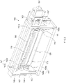
- FIG. 1 is a perspective view illustrating an apparatus for manufacturing an electrode assembly according to an embodiment of the present invention
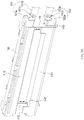
- FIG. 2 is a perspective view illustrating a cutting part of the apparatus for manufacturing the electrode assembly according to an embodiment of the present invention
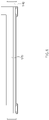
- FIG. 3 is a front view illustrating the cutting part of the apparatus for manufacturing the electrode assembly according to an embodiment of the present invention.
- an apparatus for manufacturing an electrode assembly comprises a traveling part 200 for allowing an electrode 10 to travel and a cutting part 100 for cutting the traveling electrode 10 to a predetermined size.
- the cutting part 100 comprises an upper cutting blade 110 disposed above the electrode 10, upper eccentric driving parts 151 and 152 for eccentrically driving the upper cutting blade 110, a lower cutting blade 120 disposed below the electrode 10 in a direction corresponding to the upper cutting blade 110, and lower eccentric driving parts 153 and 154 for eccentrically driving the lower cutting blade 120.
- the apparatus for manufacturing the electrode 10 assembly is an apparatus for manufacturing an electrode assembly, in which the electrode 10 and a separator are alternately stacked, by cutting and moving the electrode 10.
- the electrode assembly may be a power generation element that is chargeable and dischargeable and be accommodated in a battery case to manufacture a secondary battery.
- the electrode 10 may comprise a positive electrode and a negative electrode. Also, each of the separators separates the positive electrode from the negative electrode to electrically insulate the positive electrode from the negative electrode.
- the positive electrode may comprise a positive electrode collector and a positive electrode active material applied to the positive electrode collector.
- the positive electrode collector may be provided as foil made of an aluminum material, and the positive electrode active material may be made of lithium manganese oxide, lithium cobalt oxide, lithium nickel oxide, lithium iron phosphate, or a compound or mixture thereof containing at least one or more of the above-described materials.
- the negative electrode may comprise a negative electrode collector and a negative electrode active material applied to the negative electrode collector.
- the negative electrode collector may be provided as foil made of a copper (Cu) or nickel (Ni) material.
- the negative electrode active material may comprise synthetic graphite, lithium a metal, a lithium alloy, carbon, petroleum coke, activated carbon, graphite, a silicon compound, a tin compound, a titanium compound, or an alloy thereof.
- the negative electrode active material may further comprise, for example, non-graphite-based SiO (silica) or SiC (silicon carbide).
- the separators may be alternately stacked with respect to the positive electrode and the negative electrode, each of which is made of an insulation material.
- Each of the separator 114 may be, for example, a multi-layered film produced by microporous polyethylene, polypropylene, or a combination thereof or a polymer film for solid polymer electrolytes or gel-type polymer electrolytes such as polyvinylidene fluoride, polyethylene oxide, polyacrylonitrile, or polyvinylidene fluoride hexafluoropropylene copolymers.
- the traveling part may allow the electrode 10 to travel.
- the traveling part 200 may comprise a conveyor belt 210 to move the electrode 10.
- the traveling part 200 may be disposed in front of the cutting part 100 with respect to the traveling direction of the electrode 10 or may be disposed in each of front and rear of the cutting part 100.
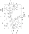
- FIG. 4 is a perspective view illustrating a portion of the cutting part of the apparatus for manufacturing the electrode assembly according to an embodiment of the present invention.
- the cutting part 100 comprises an upper cutting blade 110 disposed above the electrode 10, upper eccentric driving parts 151 and 152 for eccentrically driving the upper cutting blade 110, a lower cutting blade 120 disposed below the electrode 10 in a direction corresponding to the upper cutting blade 110, and lower eccentric driving parts 153 and 154 for eccentrically driving the lower cutting blade 120.
- the cutting part 100 may further comprise an upper mounting block 130 on which the upper cutting blade 110 is mounted, a lower mounting block 140 on which the lower cutting blade 120 is mounted, a guide rod 170 coupled between the upper mounting block 130 and the lower mounting block 140, a power transmission part 160 for transmitting power, and a support frame 180.
- An end of the upper cutting blade 110 may have a tapered shape of which a width gradually decreases toward a lower portion thereof.
- the upper cutting blade 110 and the lower cutting blade 120 are repeatedly moved in a direction in which the upper cutting blade 110 and the lower cutting blade 120 are away from each other and closer to each other to cut the electrode 10.
- the upper cutting blade 110 and the lower cutting blade 120 When the upper cutting blade 110 and the lower cutting blade 120 are moved in a direction in which the upper cutting blade 110 and the lower cutting blade 120 are closer to each other, the upper cutting blade 110 and the lower cutting blade 120 may be alternated to cross each other.
- FIG. 5 is a perspective view of the lower mounting block in the cutting part of the apparatus for manufacturing the electrode assembly according to an embodiment of the present invention
- FIG. 6 is a front view of the lower mounting block in the cutting part of the apparatus for manufacturing the electrode assembly according to an embodiment of the present invention.
- FIG. 7 is a perspective view of the upper mounting block in the cutting part of the apparatus for manufacturing the electrode assembly according to an embodiment of the present invention
- FIG. 8 is a perspective view to see-through the upper mounting block in the cutting part of the apparatus for manufacturing the electrode assembly according to an embodiment of the present invention
- FIG. 9 is a perspective view of an upper eccentric driving part and a lower eccentric driving part in the cutting part of the apparatus for manufacturing the electrode assembly according to an embodiment of the present invention.
- the upper mounting block 130 and the lower mounting block 140 may be driven by the upper eccentric driving parts 151 and 152 and the lower eccentric driving parts 153 and 154.
- the upper mounting block 130 and the lower mounting block 140 may be eccentrically coupled to the upper eccentric driving parts 151 and 152 and the lower eccentric driving parts 153 and 154 and then be rotated eccentrically.
- the cutting part 100 may further comprise a lateral pressure cylinder 190 mounted on the upper mounting block 130.
- the upper cutting blade 110 may be mounted on a front end of the upper mounting block 130, and the lateral pressure cylinder 190 may adjust a distance between the upper cutting blade 110 and the upper mounting block 130.
- the upper cutting blade 110 may be coupled to an end of the lateral pressure cylinder 190.
- the present invention is not necessarily limited thereto, and the upper cutting blade 110 may be directly coupled to the upper mounting block 130.
- FIG. 10 is a perspective view illustrating an example of a state in which the upper cutting blade and the lower cutting blade are away from each other in the cutting part of the apparatus for manufacturing the electrode assembly according to an embodiment of the present invention
- FIG. 11 is a perspective view illustrating an example of a state in which the upper cutting blade and the lower cutting blade are closer to each other in the cutting part of the apparatus for manufacturing the electrode assembly according to an embodiment of the present invention.
- the guide rod 170 may guide the upper mounting block 130 and the lower mounting block 140 to prevent the upper mounting block 130 and the lower mounting block 140 from being rotated, thereby maintaining the direction in which the upper cutting blade 110 and the lower cutting blade 120 face each other.
- the guide rod 170 is coupled between the upper mounting block 130 and the lower mounting block 140 to guide the movement of the upper mounting block 130 and the lower mounting block 140.
- a coupling hole 132 and 142 to which the guide rod 170 is coupled may be formed in each of the upper mounting block 130 and the lower mounting block 140.
- the upper mounting block 130 and the lower mounting block 140 may be moved vertically along the guide rod that is inserted into the coupling holes 132 and 142.
- the upper eccentric driving parts 151 and 152 may comprise upper eccentric blocks 151a and 52a coupled to one side of the upper mounting block 130 and upper rotating parts 151b and 152b to which the other sides of the upper eccentric blocks 151a and 152a are coupled, respectively.
- the upper eccentric blocks 151a and 152a may be rotated through the upper rotating parts 151b and 152b. At this time, the upper eccentric blocks 151a and 152a may be fixed to the rotation shafts 151c and 152c of the upper rotating parts 151b and 152b. That is, the upper eccentric blocks 151a and 152a may be coupled to the rotation shafts 151c and 152c of the upper rotational parts 151b and 152b so that relative rotational motion with respect to the rotation shafts 151c and 152c of the upper rotational parts 151b and 152b is impossible.
- the upper mounting block 130 is coupled to the upper eccentric blocks 151a and 152a so as to be eccentric with respect to the rotation shafts 151c and 152c of the upper rotating parts 151b and 152b. Also, the upper mounting block 130 may be coupled to the upper eccentric blocks 151a and 152a to enable relative rotation with respect to the upper eccentric blocks 151a and 152a.
- a bearing 131 is installed on each of side portions of the upper eccentric blocks 151a and 152a so that the upper eccentric blocks 151a and 152a are rotatably coupled.
- the bearing 131 may be an angular contact ball bearing having characteristics that are strong against a lateral load (thrust load).
- an operation method may be as follows. First, the rotation shafts 151c and 152c of the upper rotating parts 151b and 152b may be rotated in a clockwise direction. If assuming that the upper cutting blade 110 and the lower cutting blade 120 are the farthest from each other when the rotation shafts 151c and 152c of the upper rotating parts 151b and 152b are rotated at an angle of 180 degrees, when the rotation shafts 151c and 152c of the upper rotating parts 151b and 152b are further rotated at an angle of 180 degrees, the upper cutting blade 110 and the lower cutting blade 120 may be brought to the closest state.
- the upper mounting block 130 When viewed from the side, when the upper rotating parts 151b and 152b are rotated to make one revolution (360 degrees), the upper mounting block 130 may also be eccentric with the rotation shafts 151c and 152c of the upper rotating parts 151b and 152b. Thus, the upper cutting blade 110 mounted on the upper mounting block 130 may be moved up and down in a circle (see FIG. 3 ).
- the upper cutting blade 110 and the lower cutting blade 120 may be moved in a direction in which the upper cutting blade 110 and the lower cutting blade 120 are closer to each other and then may be moved in a direction in which the upper cutting blade 110 and the lower cutting blade 120 are away from each other.
- this movement may be repeatedly performed.
- more acceleration sections may be secured compared to the same rotation by increasing in eccentric width of the rotation shafts 151c and 152c of the upper mounting block 130 and the upper rotating parts 151b and 152b. That is, an eccentric rotation diameter may increase to secure more acceleration sections compared to the same rotation. Also, the eccentric rotation diameter may increase by 10 mm or more. Here, the eccentric rotation diameter may be formed to be 20 mm. Here, the eccentric rotation diameter between the lower mounting block 140 and the rotation shafts 153c and 154c of the lower rotating parts 153b and 154b may increase to correspond to the increase in diameter.
- the lower eccentric driving parts 153 and 154 may comprise lower eccentric blocks 153a and 154a each of which one side is coupled to the lower mounting block 140 and lower rotating parts 153b and 154b to which the other sides of the lower eccentric blocks 153a and 154a are respectively coupled.
- the lower eccentric blocks 153a and 154a may be rotated through the lower rotating parts 153b and 154b. At this time, the lower eccentric blocks 153a and 154a may be fixed to the rotation shafts 153c and 154c of the lower rotating parts 153b and 154b.
- the lower mounting block 140 may be rotatably coupled to the lower eccentric blocks 153a and 154a so as to be eccentric with respect to the rotation shafts 153c and 154c of the lower rotating parts 153b and 154b.
- a bearing 141 is installed on each of side portions of the lower eccentric blocks 153a and 154a so that the lower eccentric blocks 153a and 154a are rotatably coupled.
- the bearing 141 may be an angular ball bearing.
- an operation method may be as follows. First, the rotation shafts 153c and 154c of the lower rotating parts 153b and 154b may be rotated in a counterclockwise direction. If assuming that the upper cutting blade 110 and the lower cutting blade 120 are the farthest from each other when the rotation shafts 153c and 154c of the lower rotating parts 153b and 154b are rotated at an angle of 180 degrees, when the rotation shafts 153c and 154c of the lower rotating parts 153b and 154b are further rotated at an angle of 180 degrees, the upper cutting blade 110 and the lower cutting blade 120 may be brought to the closest state.
- the lower mounting block 140 When viewed from the side, when the lower rotating parts 153b and 154b are rotated to make one revolution (360 degrees), the lower mounting block 140 may also be eccentric with the rotation shafts 153c and 153c of the lower rotating parts 153b and 153b. Thus, the lower cutting blade 120 mounted on the lower mounting block 140 may be moved up and down in a circle (see FIG. 3 ).
- the upper cutting blade 110 and the lower cutting blade 120 may be moved in a direction in which the upper cutting blade 110 and the lower cutting blade 120 are closer to each other and then may be moved in a direction in which the upper cutting blade 110 and the lower cutting blade 120 are away from each other.
- this movement may be repeatedly performed.
- the power transmission part 160 may transmit power to the upper eccentric driving parts 151 and 152 and the lower eccentric driving parts 153 and 154.
- the power transmission part 160 may comprise upper gears 161 and 166 mounted on the rotation shafts 151c and 152c of the upper rotating parts 151b and 152b, lower gears 162 and 167 mounted on the rotation shafts 153c and 154c of the lower rotating parts 153b and 154b and coupled to be engaged with the upper gears 161 and 166, a power transmission gears 163 and 168 coupled to be engaged with the upper gears 161 and 166, and a power motor 164 for rotating the power transmission gears 163 and 168.
- the support frame 180 may support the upper rotating parts 151b and 152b and the lower rotating parts 153b and 154b.
- the support frame 180 may be made of a duralumin material (aluminum alloy). Thus, vibration may be minimized by reducing inertial moment. At this time, when the support frame 180 is made of a steel material, the support frame has a weigh of 58 kg, but when the support frame 180 is made of the duralumin material, the weight of the support frame 180 is reduced to 38 kg. That is, the weight was reduced by 34.5%.
- the cutting part 100 may be supported by the support frame 180, but the support frame 180 may be separated from other devices and frames other than the cutting part 100 to prevent vibration from being transmitted from other devices other than the cutting part 100.
- the upper eccentric driving parts 151 and 152, the lower eccentric driving parts 153 and 154, and the power transmission part 160 may be disposed at both sides of the support frame 180, respectively.
- the power transmission part 160 may be mounted at each of both sides of the support frame 180.
- the power transmission gears 163 and 168 may comprise a first power transmission gear 163 disposed at one side of the support frame 180 and a second power transmission gear 168 disposed at the other side of the support frame 180.
- the first power transmission gear 163 may be coupled to a rotation shaft of the power motor 164.
- the second power transmission gear 168 may be coupled through the first power transmission gear 163 and a rotation rod 165, and thus, the first power transmission gear 163 and the second power transmission gear 168 may be co-rotated by the power motor 164.
- FIGS. 2 , 3 , 10 and 11 an operation of the apparatus for manufacturing the electrode assembly according to an embodiment of the present invention will be described.
- the upper rotating parts 151b and 152b and the lower rotating parts 153b and 154b may be rotated. Also, as the rotation of the upper rotating parts 151b and 152b and the lower rotating parts 153b and 154b, the upper eccentric blocks 151a and 152a and the lower eccentric blocks 153a and 154a may be rotated to move the upper mounting block 130 and the lower mounting block 140.
- the upper mounting block 130 and the lower mounting block 140 are guided by the guide rod 170 to be moved vertically.
- the upper cutting blade 110 and the lower cutting blade 120 which are mounted on the upper mounting block 130 and the lower mounting block 140, may be repeatedly moved in a direction in which the upper cutting blade 110 and the lower cutting blade 120 are away from each other and closer to each other to cut the electrode 10.
- the upper cutting blade 110 and the lower cutting blade 120 may be eccentrically driven through the upper eccentric driving parts 151 and 152 and the lower eccentric driving parts 153 and 154 to realize speed synchronization due to the rotation. Therefore, the stop section may be removed to reduce sudden acceleration and the sudden deceleration, thereby significantly reducing the vibration and improving position quality of the electrode.
- the upper cutting blade 110 and the lower cutting blade 120 may continuously travel through the upper eccentric driving parts 151 and 152 and the lower eccentric driving parts 153 and 154 to realize high-speed cutting.
- FIG. 12 is a perspective view illustrating an apparatus for manufacturing an electrode assembly according to another embodiment of the present invention.
- an apparatus for manufacturing an electrode assembly comprises a traveling part 300 for allowing an electrode 10 to travel and a cutting part 100 for cutting the traveling electrode 10 to a predetermined size.
- the cutting part 100 comprises an upper cutting blade 110 disposed above the electrode 10, upper eccentric driving parts 151 and 152 for eccentrically driving the upper cutting blade 110, a lower cutting blade 120 disposed below the electrode 10 in a direction corresponding to the upper cutting blade 110, and lower eccentric driving parts 153 and 154 for eccentrically driving the lower cutting blade 120.
- the apparatus for manufacturing the electrode assembly according to another embodiment of the present invention is compared to the apparatus 100 for manufacturing the electrode assembly according to the foregoing embodiment of the present invention, this embodiment is different from the foregoing embodiment in configuration of the traveling part 300.
- contents duplicated with those of the apparatus for manufacturing the electrode assembly according to the foregoing embodiment and the apparatus for manufacturing the electrode assembly according to another embodiment will be omitted or briefly described, and also, only differences therebetween will be described.
- the traveling part 300 may allow the electrode 10 to travel.
- the traveling part 300 may further comprise a suction belt 310 for vacuum-suctioning the electrode 10 and a traveling means for providing moving force for moving the suction belt 310.
- the suction belt 310 may fix the electrode 10 when cutting the electrode 10 in the cutting part 100. Thus, when the electrode 10 is cut, the electrode 10 may be fixed to prevent the electrode 10 from being twisted.
- the suction belt 310 may comprise a vacuum suction part 311 that vacuum-suctions the electrode 10.
- the vacuum suction part 311 may form a plurality of suction holes to suction air through the suction holes, thereby vacuum-adsorbing and fixing the electrode 10 seated on upper ends of the suction holes.
- the vacuum suction part 311 may be connected to a vacuum suction pipe 340 to suction air through the vacuum suction pipe 340, thereby providing suction power to the vacuum suction part 311.
- the apparatus for providing the air suction force through the vacuum suction pipe 340 is a known technique, and thus, a detailed description thereof will be omitted.
- the traveling means may comprise a pulley part 320 on which the suction belt 310 is mounted on an outer circumferential surface thereof and a traveling motor 330 that rotates the pulley part 320.
- the suction belt 310 mounted in close contact with the pulley part 320 may be moved.
- FIG. 13 is a graph illustrating a motor speed deviation of a cutting part of an apparatus for manufacturing an electrode assembly according to the related art
- FIG. 14 is a graph illustrating a motor speed deviation of a cutting part of an apparatus for manufacturing an electrode assembly according to an embodiment of the present invention.
- FIG. 13 is a graph illustrating a deviation in motor speed of a cutting part of an apparatus for manufacturing an electrode assembly according to the related art
- FIG. 14 is a graph illustrating a deviation in motor speed of a cutting part of an apparatus for manufacturing an electrode assembly according to an embodiment of the present invention. That is, it shows a speed deviation between a theoretical motor RPM (A2) and an actual motor RPM (B2).
- the theoretical motor RPM (A1) and the actual motor RPM (B1) of the cutting part of the apparatus for manufacturing the electrode assembly according to the related art have a difference of about 200 RPM to about 300 RPM in a 330 minute section of a horizontal axis.
- the theoretical motor RPM (A2) and the actual motor RPM (B2) of the cutting part of the apparatus for manufacturing the electrode assembly according to an embodiment of the present invention have almost no speed deviation in all sections comprising the 330 minute section of the horizontal axis.
- the high-speed cutting may be possible, and it is seen that cutting efficiency and quality are improved as the rapid acceleration is possible when the electrode and the cutting blade collide with each other.
Landscapes
- Engineering & Computer Science (AREA)
- Manufacturing & Machinery (AREA)
- Chemical & Material Sciences (AREA)
- Chemical Kinetics & Catalysis (AREA)
- Electrochemistry (AREA)
- General Chemical & Material Sciences (AREA)
- Life Sciences & Earth Sciences (AREA)
- Forests & Forestry (AREA)
- Mechanical Engineering (AREA)
- Battery Electrode And Active Subsutance (AREA)
Abstract
Description
- The present application claims the benefit of the priority of
Korean Patent Application No. 10-2019-0161927, filed on December 06, 2019 - The present invention relates to an apparatus for manufacturing an electrode assembly, an electrode manufactured therethrough, and a secondary battery.
- Secondary batteries are rechargeable unlike primarily batteries, and also, the possibility of compact size and high capacity is high. Thus, recently, many studies on secondary batteries are being carried out.
- As technology development and demands for mobile devices increase, the demands for secondary batteries as energy sources are rapidly increasing.
- Rechargeable batteries are classified into coin type batteries, cylindrical type batteries, prismatic type batteries, and pouch type batteries according to a shape of a battery case.
- In such a secondary battery, an electrode assembly mounted in a battery case is a chargeable and dischargeable power generating device having a structure in which an electrode and a separator are stacked.
- The electrode assembly may be approximately classified into a jelly-roll type electrode assembly in which a separator is interposed between a positive electrode and a negative electrode, each of which is provided as the form of a sheet coated with an active material, and then, the positive electrode, the separator, and the negative electrode are wound, a stacked type electrode assembly in which a plurality of positive and negative electrodes with a separator therebetween are sequentially stacked, and a stack/folding type electrode assembly in which stacked type unit cells are wound together with a separation film having a long length.
- When the electrode assembly according to the related art is manufactured, after the electrode is moved to the cutting part, the cut electrode and the separator are alternately stacked to manufacture the electrode assembly.
- Here, there has been a problem in that the cutting part generates vibration during left and right reciprocating driving for speed synchronization.
- That is, there is a problem that vibration is generated as stop, acceleration, constant speed, and deceleration sections are repeated, thereby deteriorating electrode position quality after the cutting.
- Also, there has been a limit in cutting speed due to inertial moment of a heavy object in an X-axis reciprocating driving manner.
- [ Prior Art Document] (Patent Document)
Korean Patent Publication No. 10-2014-0015647 - One aspect of the present invention is to provide an apparatus for manufacturing an electrode assembly, which is capable of reducing vibration of a cutting part to improve electrode position quality when an electrode is cut, an electrode assembly manufactured therethrough, and a secondary battery.
- Another aspect of the present invention is to provide an apparatus for manufacturing an electrode assembly, which is capable of performing high-speed cutting of a cutting part when the electrode is cut, an electrode assembly manufactured therethrough, and a secondary battery.
- An apparatus for manufacturing an electrode assembly according to an embodiment of the present invention comprises a traveling part configured to allow an electrode to travel and a cutting part configured to cut the traveling electrode to a predetermined size, wherein the cutting part comprises an upper cutting blade disposed above the electrode, an upper eccentric driving part configured to eccentrically drive the upper cutting blade, a lower cutting blade disposed below the electrode in a direction corresponding to the upper cutting blade, and a lower eccentric driving part configured to eccentrically drive the lower cutting blade.
- An electrode assembly according to an embodiment of the present invention may be an electrode assembly manufactured through the apparatus for manufacturing the electrode assembly.
- A secondary battery according to an embodiment of the present invention may be a secondary battery comprising the electrode assembly manufactured through the apparatus for manufacturing the electrode assembly.
- According to the present invention, when the electrode is cut, the cutting blade may be eccentrically driven to synchronize the speed by the rotation. Therefore, the stop section may be removed to reduce the sudden acceleration and the sudden deceleration, thereby significantly reducing the vibration.
- In addition, the cutting blade may continuously travel through the eccentric driving part to increase in cutting speed.
-
-
FIG. 1 is a perspective view illustrating an apparatus for manufacturing an electrode assembly according to an embodiment of the present invention. -
FIG. 2 is a perspective view illustrating a cutting part of the apparatus for manufacturing the electrode assembly according to an embodiment of the present invention. -
FIG. 3 is a front view illustrating the cutting part of the apparatus for manufacturing the electrode assembly according to an embodiment of the present invention. -
FIG. 4 is a perspective view illustrating a portion of the cutting part of the apparatus for manufacturing the electrode assembly according to an embodiment of the present invention. -
FIG. 5 is a perspective view of a lower mounting block in the cutting part of the apparatus for manufacturing the electrode assembly according to an embodiment of the present invention. -
FIG. 6 is a front view of the lower mounting block in the cutting part of the apparatus for manufacturing the electrode assembly according to an embodiment of the present invention. -
FIG. 7 is a perspective view of an upper mounting block in the cutting part of the apparatus for manufacturing the electrode assembly according to an embodiment of the present invention. -
FIG. 8 is a perspective view to see-through the upper mounting block in the cutting part of the apparatus for manufacturing the electrode assembly according to an embodiment of the present invention. -
FIG. 9 is a perspective view of an upper eccentric driving part and a lower eccentric driving part in the cutting part of the apparatus for manufacturing the electrode assembly according to an embodiment of the present invention. -
FIG. 10 is a perspective view illustrating an example of a state in which an upper cutting blade and a lower cutting blade are away from each other in the cutting part of the apparatus for manufacturing the electrode assembly according to an embodiment of the present invention. -
FIG. 11 is a perspective view illustrating an example of a state in which the upper cutting blade and the lower cutting blade are closer to each other in the cutting part of the apparatus for manufacturing the electrode assembly according to an embodiment of the present invention. -
FIG. 12 is a perspective view illustrating an apparatus for manufacturing an electrode assembly according to another embodiment of the present invention. -
FIG. 13 is a graph illustrating a motor speed deviation of a cutting part of an apparatus for manufacturing an electrode assembly according to the related art. -
FIG. 14 is a graph illustrating a motor speed deviation of a cutting part of an apparatus for manufacturing an electrode assembly according to an embodiment of the present invention. - The objectives, specific advantages, and novel features of the present invention will become more apparent from the following detailed description taken in conjunction with the accompanying drawings. It should be noted that the reference numerals are added to the components of the drawings in the present specification with the same numerals as possible, even if they are illustrated in other drawings. Also, the present invention may be embodied in different forms and should not be construed as limited to the embodiments set forth herein. In the following description of the present invention, the detailed descriptions of related arts which may unnecessarily obscure the gist of the present invention will be omitted.
-
FIG. 1 is a perspective view illustrating an apparatus for manufacturing an electrode assembly according to an embodiment of the present invention,FIG. 2 is a perspective view illustrating a cutting part of the apparatus for manufacturing the electrode assembly according to an embodiment of the present invention, andFIG. 3 is a front view illustrating the cutting part of the apparatus for manufacturing the electrode assembly according to an embodiment of the present invention. - Referring to
FIGS. 1 to 3 , an apparatus for manufacturing an electrode assembly according to an embodiment of the present invention comprises atraveling part 200 for allowing anelectrode 10 to travel and a cuttingpart 100 for cutting the travelingelectrode 10 to a predetermined size. Thecutting part 100 comprises anupper cutting blade 110 disposed above theelectrode 10, upper eccentricdriving parts upper cutting blade 110, alower cutting blade 120 disposed below theelectrode 10 in a direction corresponding to theupper cutting blade 110, and lower eccentricdriving parts lower cutting blade 120. - In more detail, the apparatus for manufacturing the
electrode 10 assembly according to an embodiment of the present invention is an apparatus for manufacturing an electrode assembly, in which theelectrode 10 and a separator are alternately stacked, by cutting and moving theelectrode 10. - Here, the electrode assembly may be a power generation element that is chargeable and dischargeable and be accommodated in a battery case to manufacture a secondary battery.
- The
electrode 10 may comprise a positive electrode and a negative electrode. Also, each of the separators separates the positive electrode from the negative electrode to electrically insulate the positive electrode from the negative electrode. - The positive electrode may comprise a positive electrode collector and a positive electrode active material applied to the positive electrode collector. For example, the positive electrode collector may be provided as foil made of an aluminum material, and the positive electrode active material may be made of lithium manganese oxide, lithium cobalt oxide, lithium nickel oxide, lithium iron phosphate, or a compound or mixture thereof containing at least one or more of the above-described materials.
- The negative electrode may comprise a negative electrode collector and a negative electrode active material applied to the negative electrode collector. For example, the negative electrode collector may be provided as foil made of a copper (Cu) or nickel (Ni) material. The negative electrode active material may comprise synthetic graphite, lithium a metal, a lithium alloy, carbon, petroleum coke, activated carbon, graphite, a silicon compound, a tin compound, a titanium compound, or an alloy thereof. Here, the negative electrode active material may further comprise, for example, non-graphite-based SiO (silica) or SiC (silicon carbide).
- The separators may be alternately stacked with respect to the positive electrode and the negative electrode, each of which is made of an insulation material. Each of the separator 114 may be, for example, a multi-layered film produced by microporous polyethylene, polypropylene, or a combination thereof or a polymer film for solid polymer electrolytes or gel-type polymer electrolytes such as polyvinylidene fluoride, polyethylene oxide, polyacrylonitrile, or polyvinylidene fluoride hexafluoropropylene copolymers.
- Referring to
FIG. 1 , the traveling part may allow theelectrode 10 to travel. - The
traveling part 200 may comprise aconveyor belt 210 to move theelectrode 10. The travelingpart 200 may be disposed in front of the cuttingpart 100 with respect to the traveling direction of theelectrode 10 or may be disposed in each of front and rear of the cuttingpart 100. -
FIG. 4 is a perspective view illustrating a portion of the cutting part of the apparatus for manufacturing the electrode assembly according to an embodiment of the present invention. - Referring to
FIGS. 1 to 4 , the cuttingpart 100 comprises anupper cutting blade 110 disposed above theelectrode 10, uppereccentric driving parts upper cutting blade 110, alower cutting blade 120 disposed below theelectrode 10 in a direction corresponding to theupper cutting blade 110, and lowereccentric driving parts lower cutting blade 120. - The cutting
part 100 may further comprise anupper mounting block 130 on which theupper cutting blade 110 is mounted, alower mounting block 140 on which thelower cutting blade 120 is mounted, aguide rod 170 coupled between theupper mounting block 130 and thelower mounting block 140, apower transmission part 160 for transmitting power, and asupport frame 180. - An end of the
upper cutting blade 110 may have a tapered shape of which a width gradually decreases toward a lower portion thereof. - The
upper cutting blade 110 and thelower cutting blade 120 are repeatedly moved in a direction in which theupper cutting blade 110 and thelower cutting blade 120 are away from each other and closer to each other to cut theelectrode 10. - When the
upper cutting blade 110 and thelower cutting blade 120 are moved in a direction in which theupper cutting blade 110 and thelower cutting blade 120 are closer to each other, theupper cutting blade 110 and thelower cutting blade 120 may be alternated to cross each other. -
FIG. 5 is a perspective view of the lower mounting block in the cutting part of the apparatus for manufacturing the electrode assembly according to an embodiment of the present invention, andFIG. 6 is a front view of the lower mounting block in the cutting part of the apparatus for manufacturing the electrode assembly according to an embodiment of the present invention. -
FIG. 7 is a perspective view of the upper mounting block in the cutting part of the apparatus for manufacturing the electrode assembly according to an embodiment of the present invention,FIG. 8 is a perspective view to see-through the upper mounting block in the cutting part of the apparatus for manufacturing the electrode assembly according to an embodiment of the present invention, andFIG. 9 is a perspective view of an upper eccentric driving part and a lower eccentric driving part in the cutting part of the apparatus for manufacturing the electrode assembly according to an embodiment of the present invention. - Referring to
FIGS. 3 and5 to 9 , theupper mounting block 130 and thelower mounting block 140 may be driven by the uppereccentric driving parts eccentric driving parts - The
upper mounting block 130 and thelower mounting block 140 may be eccentrically coupled to the uppereccentric driving parts eccentric driving parts - The cutting
part 100 may further comprise alateral pressure cylinder 190 mounted on theupper mounting block 130. Here, theupper cutting blade 110 may be mounted on a front end of theupper mounting block 130, and thelateral pressure cylinder 190 may adjust a distance between theupper cutting blade 110 and theupper mounting block 130. Thus, it is possible to adjust an intersection point or an intersection distance between theupper cutting blade 110 and thelower cutting blade 120. At this time, theupper cutting blade 110 may be coupled to an end of thelateral pressure cylinder 190. However, the present invention is not necessarily limited thereto, and theupper cutting blade 110 may be directly coupled to theupper mounting block 130. -
FIG. 10 is a perspective view illustrating an example of a state in which the upper cutting blade and the lower cutting blade are away from each other in the cutting part of the apparatus for manufacturing the electrode assembly according to an embodiment of the present invention, andFIG. 11 is a perspective view illustrating an example of a state in which the upper cutting blade and the lower cutting blade are closer to each other in the cutting part of the apparatus for manufacturing the electrode assembly according to an embodiment of the present invention. - Referring to
FIGS. 10 and11 , theguide rod 170 may guide theupper mounting block 130 and thelower mounting block 140 to prevent theupper mounting block 130 and thelower mounting block 140 from being rotated, thereby maintaining the direction in which theupper cutting blade 110 and thelower cutting blade 120 face each other. - Referring to
FIGS. 3 and7 to 11 , theguide rod 170 is coupled between theupper mounting block 130 and thelower mounting block 140 to guide the movement of theupper mounting block 130 and thelower mounting block 140. - Here, a
coupling hole guide rod 170 is coupled may be formed in each of theupper mounting block 130 and thelower mounting block 140. Thus, when theupper mounting block 130 and thelower mounting block 140 are moved by the uppereccentric driving parts eccentric driving parts upper mounting block 130 and thelower mounting block 140 may be moved vertically along the guide rod that is inserted into the coupling holes 132 and 142. - Referring to
FIGS. 2 ,3 ,10 , and11 , the uppereccentric driving parts eccentric blocks 151a and 52a coupled to one side of theupper mounting block 130 and upperrotating parts eccentric blocks - The upper
eccentric blocks rotating parts eccentric blocks rotation shafts rotating parts eccentric blocks rotation shafts rotational parts rotation shafts rotational parts - Also, the
upper mounting block 130 is coupled to the uppereccentric blocks rotation shafts rotating parts upper mounting block 130 may be coupled to the uppereccentric blocks eccentric blocks - Here, a
bearing 131 is installed on each of side portions of the uppereccentric blocks eccentric blocks bearing 131 may be an angular contact ball bearing having characteristics that are strong against a lateral load (thrust load). - Referring to
FIGS. 10 and11 , an operation method may be as follows. First, therotation shafts rotating parts upper cutting blade 110 and thelower cutting blade 120 are the farthest from each other when therotation shafts rotating parts rotation shafts rotating parts upper cutting blade 110 and thelower cutting blade 120 may be brought to the closest state. When viewed from the side, when the upperrotating parts upper mounting block 130 may also be eccentric with therotation shafts rotating parts upper cutting blade 110 mounted on theupper mounting block 130 may be moved up and down in a circle (seeFIG. 3 ). - Since the
lower mounting block 140 is moved in synchronization with each other in the same manner as theupper mounting block 130, theupper cutting blade 110 and thelower cutting blade 120 may be moved in a direction in which theupper cutting blade 110 and thelower cutting blade 120 are closer to each other and then may be moved in a direction in which theupper cutting blade 110 and thelower cutting blade 120 are away from each other. Here, this movement may be repeatedly performed. - Referring to
FIGS. 2 ,3 ,10 and11 , more acceleration sections may be secured compared to the same rotation by increasing in eccentric width of therotation shafts upper mounting block 130 and the upperrotating parts lower mounting block 140 and therotation shafts rotating parts - The lower
eccentric driving parts eccentric blocks lower mounting block 140 and lowerrotating parts eccentric blocks - The lower
eccentric blocks rotating parts eccentric blocks rotation shafts rotating parts - The
lower mounting block 140 may be rotatably coupled to the lowereccentric blocks rotation shafts rotating parts bearing 141 is installed on each of side portions of the lowereccentric blocks eccentric blocks bearing 141 may be an angular ball bearing. - Referring to
FIGS. 10 and11 , an operation method may be as follows. First, therotation shafts rotating parts upper cutting blade 110 and thelower cutting blade 120 are the farthest from each other when therotation shafts rotating parts rotation shafts rotating parts upper cutting blade 110 and thelower cutting blade 120 may be brought to the closest state. When viewed from the side, when the lowerrotating parts lower mounting block 140 may also be eccentric with therotation shafts rotating parts lower cutting blade 120 mounted on thelower mounting block 140 may be moved up and down in a circle (seeFIG. 3 ). - Since the
upper mounting block 130 is moved in synchronization with each other in the same manner as thelower mounting block 140, theupper cutting blade 110 and thelower cutting blade 120 may be moved in a direction in which theupper cutting blade 110 and thelower cutting blade 120 are closer to each other and then may be moved in a direction in which theupper cutting blade 110 and thelower cutting blade 120 are away from each other. Here, this movement may be repeatedly performed. - Referring to
FIGS. 2 and3 , thepower transmission part 160 may transmit power to the uppereccentric driving parts eccentric driving parts - The
power transmission part 160 may compriseupper gears rotation shafts rotating parts lower gears rotation shafts rotating parts upper gears upper gears power motor 164 for rotating the power transmission gears 163 and 168. - The
support frame 180 may support the upperrotating parts rotating parts - The
support frame 180 may be made of a duralumin material (aluminum alloy). Thus, vibration may be minimized by reducing inertial moment. At this time, when thesupport frame 180 is made of a steel material, the support frame has a weigh of 58 kg, but when thesupport frame 180 is made of the duralumin material, the weight of thesupport frame 180 is reduced to 38 kg. That is, the weight was reduced by 34.5%. - Here, the cutting
part 100 may be supported by thesupport frame 180, but thesupport frame 180 may be separated from other devices and frames other than the cuttingpart 100 to prevent vibration from being transmitted from other devices other than the cuttingpart 100. - The upper
eccentric driving parts eccentric driving parts power transmission part 160 may be disposed at both sides of thesupport frame 180, respectively. - The
power transmission part 160 may be mounted at each of both sides of thesupport frame 180. - The power transmission gears 163 and 168 may comprise a first
power transmission gear 163 disposed at one side of thesupport frame 180 and a secondpower transmission gear 168 disposed at the other side of thesupport frame 180. - The first
power transmission gear 163 may be coupled to a rotation shaft of thepower motor 164. - The second
power transmission gear 168 may be coupled through the firstpower transmission gear 163 and arotation rod 165, and thus, the firstpower transmission gear 163 and the secondpower transmission gear 168 may be co-rotated by thepower motor 164. - Referring to
FIGS. 2 ,3 ,10 and11 , an operation of the apparatus for manufacturing the electrode assembly according to an embodiment of the present invention will be described. - As the
power transmission gear 168 is rotated, the upperrotating parts rotating parts rotating parts rotating parts eccentric blocks eccentric blocks upper mounting block 130 and thelower mounting block 140. Here, theupper mounting block 130 and thelower mounting block 140 are guided by theguide rod 170 to be moved vertically. At this time, theupper cutting blade 110 and thelower cutting blade 120, which are mounted on theupper mounting block 130 and thelower mounting block 140, may be repeatedly moved in a direction in which theupper cutting blade 110 and thelower cutting blade 120 are away from each other and closer to each other to cut theelectrode 10. - Thus, when the
electrode 10 is cut through the cuttingpart 100, theupper cutting blade 110 and thelower cutting blade 120 may be eccentrically driven through the uppereccentric driving parts eccentric driving parts - In addition, the
upper cutting blade 110 and thelower cutting blade 120 may continuously travel through the uppereccentric driving parts eccentric driving parts - Hereinafter, an apparatus for manufacturing an electrode assembly according to another embodiment of the present invention will be described.
-
FIG. 12 is a perspective view illustrating an apparatus for manufacturing an electrode assembly according to another embodiment of the present invention. - Referring to
FIG. 12 , an apparatus for manufacturing an electrode assembly according to another embodiment of the present invention comprises a travelingpart 300 for allowing anelectrode 10 to travel and a cuttingpart 100 for cutting the travelingelectrode 10 to a predetermined size. The cuttingpart 100 comprises anupper cutting blade 110 disposed above theelectrode 10, uppereccentric driving parts upper cutting blade 110, alower cutting blade 120 disposed below theelectrode 10 in a direction corresponding to theupper cutting blade 110, and lowereccentric driving parts lower cutting blade 120. - When the apparatus for manufacturing the electrode assembly according to another embodiment of the present invention is compared to the
apparatus 100 for manufacturing the electrode assembly according to the foregoing embodiment of the present invention, this embodiment is different from the foregoing embodiment in configuration of the travelingpart 300. Thus, in the apparatus for manufacturing the electrode assembly according to another embodiment of the present invention, contents duplicated with those of the apparatus for manufacturing the electrode assembly according to the foregoing embodiment and the apparatus for manufacturing the electrode assembly according to another embodiment will be omitted or briefly described, and also, only differences therebetween will be described. - In more detail, the traveling
part 300 may allow theelectrode 10 to travel. - The traveling
part 300 may further comprise asuction belt 310 for vacuum-suctioning theelectrode 10 and a traveling means for providing moving force for moving thesuction belt 310. - The
suction belt 310 may fix theelectrode 10 when cutting theelectrode 10 in the cuttingpart 100. Thus, when theelectrode 10 is cut, theelectrode 10 may be fixed to prevent theelectrode 10 from being twisted. - The
suction belt 310 may comprise avacuum suction part 311 that vacuum-suctions theelectrode 10. - The
vacuum suction part 311 may form a plurality of suction holes to suction air through the suction holes, thereby vacuum-adsorbing and fixing theelectrode 10 seated on upper ends of the suction holes. - At this time, the
vacuum suction part 311 may be connected to avacuum suction pipe 340 to suction air through thevacuum suction pipe 340, thereby providing suction power to thevacuum suction part 311. - Here, the apparatus for providing the air suction force through the
vacuum suction pipe 340 is a known technique, and thus, a detailed description thereof will be omitted. - Also, the traveling means may comprise a
pulley part 320 on which thesuction belt 310 is mounted on an outer circumferential surface thereof and a travelingmotor 330 that rotates thepulley part 320. - Here, when a rotation shaft of the traveling
motor 330 is rotated to rotate thepulley part 320, thesuction belt 310 mounted in close contact with thepulley part 320 may be moved. -
FIG. 13 is a graph illustrating a motor speed deviation of a cutting part of an apparatus for manufacturing an electrode assembly according to the related art, andFIG. 14 is a graph illustrating a motor speed deviation of a cutting part of an apparatus for manufacturing an electrode assembly according to an embodiment of the present invention. -
FIG. 13 is a graph illustrating a deviation in motor speed of a cutting part of an apparatus for manufacturing an electrode assembly according to the related art, andFIG. 14 is a graph illustrating a deviation in motor speed of a cutting part of an apparatus for manufacturing an electrode assembly according to an embodiment of the present invention. That is, it shows a speed deviation between a theoretical motor RPM (A2) and an actual motor RPM (B2). - Referring to
FIG. 13 , the theoretical motor RPM (A1) and the actual motor RPM (B1) of the cutting part of the apparatus for manufacturing the electrode assembly according to the related art have a difference of about 200 RPM to about 300 RPM in a 330 minute section of a horizontal axis. - Referring to
FIG. 14 , the theoretical motor RPM (A2) and the actual motor RPM (B2) of the cutting part of the apparatus for manufacturing the electrode assembly according to an embodiment of the present invention have almost no speed deviation in all sections comprising the 330 minute section of the horizontal axis. - Therefore, when the electrode is cut through the cutting part of the apparatus for manufacturing the electrode assembly according to an embodiment of the present invention, the high-speed cutting may be possible, and it is seen that cutting efficiency and quality are improved as the rapid acceleration is possible when the electrode and the cutting blade collide with each other.
- While the present invention has been particularly shown and described with reference to exemplary embodiments thereof, it is to be understood that the scope of the present invention is not limited to the apparatus for manufacturing the electrode assembly according to the present invention. It will be understood by those of ordinary skill in the art that various changes in form and details may be made therein without departing from the spirit and scope of the present invention.
- Furthermore, the scope of protection of the present invention will be clarified by the appended claims.
-
- 10:
- Electrode
- 100:
- Cutting part
- 110:
- Upper cutting blade
- 120:
- Lower cutting blade
- 130:
- Upper mounting block
- 131:
- Bearing
- 132:
- Coupling hole
- 140:
- Lower mounting block
- 141:
- Bearing
- 142:
- Coupling hole
- 151:
- First upper eccentric driving part
- 151a:
- First upper eccentric block
- 151b:
- First upper rotating part
- 151c:
- Rotation shaft
- 152:
- Second upper eccentric driving part
- 152a:
- Second upper eccentric block
- 152b:
- Second upper rotating part
- 152c:
- Rotation shaft
- 153:
- First lower eccentric driving part
- 153a:
- First lower eccentric block
- 153b:
- First lower rotating part
- 153c:
- Rotation shaft
- 154:
- Second upper eccentric driving part
- 154a:
- Second lower eccentric block
- 154b:
- Second lower rotating part
-
- 154c:
- Rotation shaft
- 160:
- Power transmission part
- 161:
- First upper gear
- 162:
- First lower gear
- 163:
- First power transmission gear
- 164:
- Power motor
- 165:
- Rotation rod
- 166:
- Second upper gear
- 167:
- Second lower gear
- 168:
- Second power transmission gear
- 170:
- Guide rod
- 180:
- Support frame
- 190:
- Lateral pressure cylinder
- 200,
- 300: Traveling part
- 210:
- Conveyor belt
- 310:
- Suction belt
- 311:
- Vacuum suction part
- 320:
- Pulley part
- 330:
- Traveling motor
- 340:
- Vacuum suction pipe
Claims (15)
- An apparatus for manufacturing an electrode assembly, comprising:a traveling part configured to allow an electrode to travel; anda cutting part configured to cut the traveling electrode to a predetermined size,wherein the cutting part comprises:an upper cutting blade disposed above the electrode;an upper eccentric driving part configured to eccentrically drive the upper cutting blade;a lower cutting blade disposed below the electrode in a direction corresponding to the upper cutting blade; anda lower eccentric driving part configured to eccentrically drive the lower cutting blade.
- The apparatus of claim 1, wherein the upper cutting blade and the lower cutting blade are repeatedly moved in a direction, in which the upper cutting blade and the lower cutting blade are closer to each other and away from each other, to cut the electrode.
- The apparatus of claim 2, wherein the upper cutting blade and the lower cutting blade are alternated to cross each other in the direction in which the upper cutting blade and the lower cutting blade are closer to each other.
- The apparatus of claim 3, wherein an end of the upper cutting blade has a tapered shape of which a width gradually decreases toward a lower portion thereof so that the electrode is cut.
- The apparatus of claim 1, wherein the cutting part further comprises:an upper mounting block on which the upper cutting blade is mounted; anda lower mounting block on which the lower cutting blade is mounted,wherein the upper mounting block and the lower mounting block are driven by the upper eccentric driving part and the lower eccentric driving part, respectively.
- The apparatus of claim 5, wherein the upper mounting block and the lower mounting block are eccentrically coupled to the upper eccentric driving part and the lower eccentric driving part so as to be eccentrically rotated.
- The apparatus of claim 6, wherein the cutting part further comprises a guide rod coupled between the upper mounting block and the lower mounting block,
wherein the guide rod guides the upper mounting block and the lower mounting block so as not to be rotated so that the upper cutting blade and the lower cutting blade, which are respectively mounted on the upper mounting block and the lower mounting block, are maintained in a direction facing each other. - The apparatus of claim 7, wherein a coupling hole to which the guide rod is coupled is formed in each of the upper mounting block and the lower mounting block, and
the upper mounting block and the lower mounting block are moved vertically along the guide rod when the upper mounting block and the lower mounting block are moved by the upper eccentric driving part and the lower eccentric driving part. - The apparatus of claim 7, wherein the upper eccentric driving part comprises: an upper eccentric block of which one side is coupled to the upper mounting block; and an upper rotating part to which the other side of the upper eccentric block is coupled,the upper eccentric block is rotated through the upper rotating part,the upper mounting block is rotatably coupled to the upper eccentric block so as to be eccentric with respect to a rotation shaft of the upper rotating part,the lower eccentric driving part comprises: a lower eccentric block of which one side is coupled to the lower mounting block; and a lower rotating part to which the other side of the lower eccentric block is coupled,the lower eccentric block is rotated through the lower rotating part, andthe lower mounting block is rotatably coupled to the lower eccentric block so as to be eccentric with respect to a rotation shaft of the lower rotating part.
- The apparatus of claim 9, wherein the cutting part further comprises a power transmission part configured to transmit power to the upper eccentric driving part and the lower eccentric driving part,
wherein the power transmission part comprises:an upper gear mounted on the rotation shaft of the upper rotating part;a lower gear mounted on the rotation shaft of the lower rotating part and coupled to be engaged with the upper gear;a power transmission gear coupled to engaged with the upper gear; anda power motor configured to rotate the power transmission gear. - The apparatus of claim 10, wherein the cutting part further comprises a support frame configured to support the upper rotating part and the lower rotating part,the upper eccentric driving part, the lower eccentric driving part, and the power transmission part are disposed at each of both sides of the support frame, andthe power transmission part is mounted on each of both the sides of the support frame.
- The apparatus of claim 11, wherein the power transmission gear comprises a first power transmission gear disposed at one side of the support frame and a second power transmission gear disposed at the other side of the support frame,wherein the first power transmission gear is coupled to a rotation shaft of the power motor, andthe second power transmission gear is coupled to the first power transmission gear through a rotation rod so that the first power transmission gear and the second power transmission gear are co-rotated by the power motor.
- The apparatus of claim 1, wherein the traveling part comprises a suction belt configured to vacuum-suction the electrode so as to move the electrode, and
the suction belt fixes the electrode when the electrode is cut in the cutting part. - An electrode assembly manufactured through the apparatus for manufacturing the electrode assembly of any one of claims 1 to 13.
- A secondary battery comprising the electrode assembly manufactured through the apparatus for manufacturing the electrode assembly of any one of claims 1 to 13.
Applications Claiming Priority (2)
| Application Number | Priority Date | Filing Date | Title |
|---|---|---|---|
| KR1020190161927A KR102757892B1 (en) | 2019-12-06 | 2019-12-06 | Electrode assembly manufacturing device, electrode assembly manufactured from thereof and rechargeable battery |
| PCT/KR2020/017449 WO2021112553A1 (en) | 2019-12-06 | 2020-12-02 | Electrode assembly manufacturing apparatus, electrode assembly manufactured thereby and secondary battery |
Publications (2)
| Publication Number | Publication Date |
|---|---|
| EP4047700A1 true EP4047700A1 (en) | 2022-08-24 |
| EP4047700A4 EP4047700A4 (en) | 2023-05-03 |
Family
ID=76221812
Family Applications (1)
| Application Number | Title | Priority Date | Filing Date |
|---|---|---|---|
| EP20895511.2A Pending EP4047700A4 (en) | 2019-12-06 | 2020-12-02 | ELECTRODE ASSEMBLY MANUFACTURING APPARATUS, ELECTRODE ASSEMBLY SO MANUFACTURED AND SECONDARY BATTERY |
Country Status (5)
| Country | Link |
|---|---|
| US (1) | US12537182B2 (en) |
| EP (1) | EP4047700A4 (en) |
| KR (1) | KR102757892B1 (en) |
| CN (1) | CN114762160A (en) |
| WO (1) | WO2021112553A1 (en) |
Families Citing this family (2)
| Publication number | Priority date | Publication date | Assignee | Title |
|---|---|---|---|---|
| KR102920008B1 (en) * | 2022-12-23 | 2026-01-29 | 주식회사 엘지에너지솔루션 | Conveying system for conveying connecting member |
| US12288863B1 (en) * | 2023-10-20 | 2025-04-29 | Shenzhen Ept Battery Co., Ltd | Method for preparing negative electrode sheet of nickel-metal hydride battery |
Family Cites Families (31)
| Publication number | Priority date | Publication date | Assignee | Title |
|---|---|---|---|---|
| US2640539A (en) * | 1949-07-26 | 1953-06-02 | Powers Samas Account Mach Ltd | Apparatus for cutting lengths from a web of paper, cardboard or similar material |
| US3128660A (en) * | 1960-04-04 | 1964-04-14 | Rene J Gaubert | Web cutting mechanism |
| US4027564A (en) * | 1976-06-23 | 1977-06-07 | Kabushiki Kaisha Token Kikai Seisakusho | Machine for cutting a moving strip of material |
| KR830001450Y1 (en) | 1976-07-20 | 1983-08-13 | 미쓰비시 지도오샤 고오교오 가부시기 가이샤 | Reciprocating engine air pump unit |
| CA1045969A (en) * | 1976-12-08 | 1979-01-09 | Kabushiki Kaisha Token Kikai Seisakusho (Token Machinery Works Co., Ltd. ) | Machine for cutting a moving strip of material |
| CA1072004A (en) * | 1977-06-17 | 1980-02-19 | Merrill D. Martin | Rotary shear machine |
| CN2326004Y (en) * | 1998-02-11 | 1999-06-30 | 杨箴立 | Tobacco thin-sheet slicing appparatus |
| IT1299688B1 (en) * | 1998-07-23 | 2000-03-24 | Pfm Spa | PROCEDURE FOR THE SUBDIVISION OF A RIBBON OR STRAND OF GUMMY PRODUCT IN SINGLE PORTIONS AND A DEVICE FOR THE INSTALLATION OF |
| US7021185B2 (en) * | 2001-10-26 | 2006-04-04 | Goss International Americas, Inc. | Registration apparatus for a sheet material article handler |
| JP4301819B2 (en) * | 2003-01-15 | 2009-07-22 | 株式会社東京自働機械製作所 | Film cutting device |
| JP2005254381A (en) * | 2004-03-11 | 2005-09-22 | Konica Minolta Medical & Graphic Inc | Cutting device and contact force setting method of disc type upper blade and cylindrical lower blade |
| KR101106337B1 (en) * | 2004-09-22 | 2012-01-18 | 삼성에스디아이 주식회사 | Electrode plate cutting device |
| KR200450893Y1 (en) * | 2010-05-26 | 2010-11-08 | 장성환 | Packing device |
| KR101271492B1 (en) | 2010-12-02 | 2013-06-05 | 주식회사 엘지화학 | Novel Device for Cutting Electrode Sheet and Secondary Battery Manufactured Using the Same |
| KR101198345B1 (en) * | 2011-03-31 | 2012-11-06 | (주)유피아이 | Cut to length machine using cam for transformer core |
| AU2012267912B2 (en) * | 2011-06-07 | 2017-04-20 | Risco Usa Corporation | Machine and method for high speed cutting and portioning of extruded products |
| KR101307875B1 (en) | 2012-01-30 | 2013-09-13 | 주식회사 엠플러스 | Secondary battery electrode panel stamping apparatus |
| KR101337226B1 (en) * | 2012-03-09 | 2013-12-05 | 유일에너테크(주) | Cutting apparatus for electrodes of battery |
| KR101528001B1 (en) | 2012-06-22 | 2015-06-10 | 주식회사 엘지화학 | Electrode assembly, manufacture thereof, and secondary batteries including same |
| KR101479723B1 (en) | 2012-07-06 | 2015-01-08 | 유일에너테크(주) | System for producing electrodes of battery and feeding apparatus used for the system |
| KR20140018561A (en) * | 2012-08-02 | 2014-02-13 | 한국타이어 주식회사 | Cutting apparatus of reinforcement belt for tire |
| JP5667134B2 (en) | 2012-09-21 | 2015-02-12 | Ckd株式会社 | Cutting device and winding device |
| KR101564537B1 (en) | 2012-12-05 | 2015-10-29 | 닛산 지도우샤 가부시키가이샤 | Electrical device separator severing apparatus and severing method |
| KR101575152B1 (en) | 2014-03-04 | 2015-12-07 | 주식회사 디에이테크놀로지 | Apparatus for Cutting Electrode Film for Secondary Battery |
| KR102273773B1 (en) * | 2014-09-04 | 2021-07-06 | 삼성에스디아이 주식회사 | Rolling device for secondary battery and rolling method for the same |
| CN204621207U (en) * | 2015-05-12 | 2015-09-09 | 武汉开锐智能设备有限公司 | A kind of twolip welding shear |
| CN205033262U (en) | 2015-10-13 | 2016-02-17 | 重庆佳宝成能源科技有限公司 | Device is cut to electrode slice |
| JP6720516B2 (en) | 2015-12-14 | 2020-07-08 | 株式会社豊田自動織機 | Electrode cutting device and electrode inspection method |
| KR101743873B1 (en) | 2016-06-13 | 2017-06-20 | 박종택 | Side sealing machine of zipper bag |
| JP2018026334A (en) | 2016-07-27 | 2018-02-15 | 株式会社豊田自動織機 | Electrode of power storage device, manufacturing apparatus of electrode and manufacturing method of electrode |
| KR101959082B1 (en) | 2018-09-07 | 2019-03-18 | 조기봉 | Method and apparatus for stacking secondary battery cell elements |
-
2019
- 2019-12-06 KR KR1020190161927A patent/KR102757892B1/en active Active
-
2020
- 2020-12-02 EP EP20895511.2A patent/EP4047700A4/en active Pending
- 2020-12-02 US US17/782,026 patent/US12537182B2/en active Active
- 2020-12-02 WO PCT/KR2020/017449 patent/WO2021112553A1/en not_active Ceased
- 2020-12-02 CN CN202080084582.XA patent/CN114762160A/en active Pending
Also Published As
| Publication number | Publication date |
|---|---|
| CN114762160A (en) | 2022-07-15 |
| KR102757892B1 (en) | 2025-01-22 |
| WO2021112553A1 (en) | 2021-06-10 |
| KR20210071588A (en) | 2021-06-16 |
| US12537182B2 (en) | 2026-01-27 |
| EP4047700A4 (en) | 2023-05-03 |
| US20230012356A1 (en) | 2023-01-12 |
Similar Documents
| Publication | Publication Date | Title |
|---|---|---|
| US12492095B2 (en) | Apparatus for manufacturing electrode assembly, electrode assembly manufactured therethrough, and secondary battery | |
| TWI447988B (en) | Method for degassing secondary battery using centrifugal force | |
| US12424651B2 (en) | Apparatus for picking and placing battery cell elements and high speed stacking apparatus including same | |
| US12537182B2 (en) | Apparatus for manufacturing electrode assembly, electrode assembly manufactured therethrough, and secondary battery | |
| KR101428033B1 (en) | Device for Folding Electrode Assembly | |
| EP4068444B1 (en) | Apparatus and method for manufacturing secondary battery | |
| CN103443989A (en) | Mandrels for the manufacture of jelly-roll electrode assemblies | |
| EP3907031A1 (en) | Slitter | |
| JP5798050B2 (en) | Secondary battery, storage battery system using the secondary battery, and maintenance method | |
| CA3252585A1 (en) | Laser notching apparatus | |
| CN105406101A (en) | Rolling device for secondary battery and rolling method for the same | |
| EP3155672B1 (en) | Battery and battery manufacturing method | |
| JP6451740B2 (en) | Rolled sheet material holding device and battery laminate manufacturing method | |
| KR102401675B1 (en) | A apparatus for stacking the electrodes or secondary battery | |
| JP2002042793A (en) | Winding device and winding method | |
| KR20230076745A (en) | Electrode Assembly, Method and Apparatus for Manufacturing the same, Cylindrical battery including the Electrode Assembly, and Battery pack and Vehicle including the Cylindrical batter | |
| KR20230162954A (en) | Manufacturing method and stacking device for electrode stack | |
| US20250015334A1 (en) | Cutting device, electrode assembly, cylindrical battery cell, electrode assembly manufacturing device, battery pack and vehicle including the electrode assembly, and battery cell manufacturing method | |
| US20260128352A1 (en) | Electrode plate cutting unit for secondary battery, secondary battery manufacturing apparatus having electrode plate cutting unit, and method of manufacturing secondary battery | |
| EP4614691A1 (en) | Secondary battery manufacturing apparatus and secondary battery manufacturing method | |
| US11955591B2 (en) | Method for manufacturing secondary battery and apparatus for manufacturing secondary battery | |
| US11545693B1 (en) | Flag forming device after laser notching of secondary batteries for electric vehicles | |
| US20260128349A1 (en) | Electrode plate cutting machine for secondary battery and secondary battery manufacturing apparatus having electrode plate cutting machine | |
| US20250343246A1 (en) | Electrode plate for secondary battery, secondary battery including same, and method of manufacturing same | |
| CN116648324A (en) | Method for marking groups of electrode structures in a web with a laser |
Legal Events
| Date | Code | Title | Description |
|---|---|---|---|
| STAA | Information on the status of an ep patent application or granted ep patent |
Free format text: STATUS: THE INTERNATIONAL PUBLICATION HAS BEEN MADE |
|
| PUAI | Public reference made under article 153(3) epc to a published international application that has entered the european phase |
Free format text: ORIGINAL CODE: 0009012 |
|
| STAA | Information on the status of an ep patent application or granted ep patent |
Free format text: STATUS: REQUEST FOR EXAMINATION WAS MADE |
|
| 17P | Request for examination filed |
Effective date: 20220520 |
|
| AK | Designated contracting states |
Kind code of ref document: A1 Designated state(s): AL AT BE BG CH CY CZ DE DK EE ES FI FR GB GR HR HU IE IS IT LI LT LU LV MC MK MT NL NO PL PT RO RS SE SI SK SM TR |
|
| DAV | Request for validation of the european patent (deleted) | ||
| DAX | Request for extension of the european patent (deleted) | ||
| A4 | Supplementary search report drawn up and despatched |
Effective date: 20230404 |
|
| RIC1 | Information provided on ipc code assigned before grant |
Ipc: B26D 1/00 20060101ALN20230329BHEP Ipc: B26D 5/08 20060101ALI20230329BHEP Ipc: B26D 1/06 20060101ALI20230329BHEP Ipc: H01M 10/052 20100101ALI20230329BHEP Ipc: H01M 10/04 20060101AFI20230329BHEP |