EP4047601A2 - Träger zur erzeugung von komfortgeräuschen und erzeugung von komfortgeräuschen - Google Patents
Träger zur erzeugung von komfortgeräuschen und erzeugung von komfortgeräuschen Download PDFInfo
- Publication number
- EP4047601A2 EP4047601A2 EP22151769.1A EP22151769A EP4047601A2 EP 4047601 A2 EP4047601 A2 EP 4047601A2 EP 22151769 A EP22151769 A EP 22151769A EP 4047601 A2 EP4047601 A2 EP 4047601A2
- Authority
- EP
- European Patent Office
- Prior art keywords
- parameter
- prediction
- weight factor
- vector
- receiving node
- Prior art date
- Legal status (The legal status is an assumption and is not a legal conclusion. Google has not performed a legal analysis and makes no representation as to the accuracy of the status listed.)
- Withdrawn
Links
- 238000000034 method Methods 0.000 claims abstract description 66
- 230000005236 sound signal Effects 0.000 claims abstract description 23
- 230000003595 spectral effect Effects 0.000 claims description 16
- 230000011664 signaling Effects 0.000 claims description 11
- 238000004590 computer program Methods 0.000 description 36
- 238000012545 processing Methods 0.000 description 34
- 238000004891 communication Methods 0.000 description 27
- 238000001228 spectrum Methods 0.000 description 11
- 238000010586 diagram Methods 0.000 description 7
- 230000007246 mechanism Effects 0.000 description 7
- 230000006870 function Effects 0.000 description 5
- 230000000694 effects Effects 0.000 description 4
- 230000003287 optical effect Effects 0.000 description 4
- 230000001360 synchronised effect Effects 0.000 description 4
- 230000005540 biological transmission Effects 0.000 description 2
- 230000002085 persistent effect Effects 0.000 description 2
- 238000005070 sampling Methods 0.000 description 2
- 238000007493 shaping process Methods 0.000 description 2
- 239000007787 solid Substances 0.000 description 2
- 238000012549 training Methods 0.000 description 2
- 238000013459 approach Methods 0.000 description 1
- 238000004364 calculation method Methods 0.000 description 1
- 230000009977 dual effect Effects 0.000 description 1
- 230000007274 generation of a signal involved in cell-cell signaling Effects 0.000 description 1
- 230000008447 perception Effects 0.000 description 1
- 230000002035 prolonged effect Effects 0.000 description 1
- 230000035807 sensation Effects 0.000 description 1
Images


Classifications
-
- G—PHYSICS
- G10—MUSICAL INSTRUMENTS; ACOUSTICS
- G10L—SPEECH ANALYSIS TECHNIQUES OR SPEECH SYNTHESIS; SPEECH RECOGNITION; SPEECH OR VOICE PROCESSING TECHNIQUES; SPEECH OR AUDIO CODING OR DECODING
- G10L19/00—Speech or audio signals analysis-synthesis techniques for redundancy reduction, e.g. in vocoders; Coding or decoding of speech or audio signals, using source filter models or psychoacoustic analysis
- G10L19/0017—Lossless audio signal coding; Perfect reconstruction of coded audio signal by transmission of coding error
-
- G—PHYSICS
- G10—MUSICAL INSTRUMENTS; ACOUSTICS
- G10L—SPEECH ANALYSIS TECHNIQUES OR SPEECH SYNTHESIS; SPEECH RECOGNITION; SPEECH OR VOICE PROCESSING TECHNIQUES; SPEECH OR AUDIO CODING OR DECODING
- G10L19/00—Speech or audio signals analysis-synthesis techniques for redundancy reduction, e.g. in vocoders; Coding or decoding of speech or audio signals, using source filter models or psychoacoustic analysis
- G10L19/008—Multichannel audio signal coding or decoding using interchannel correlation to reduce redundancy, e.g. joint-stereo, intensity-coding or matrixing
-
- G—PHYSICS
- G10—MUSICAL INSTRUMENTS; ACOUSTICS
- G10L—SPEECH ANALYSIS TECHNIQUES OR SPEECH SYNTHESIS; SPEECH RECOGNITION; SPEECH OR VOICE PROCESSING TECHNIQUES; SPEECH OR AUDIO CODING OR DECODING
- G10L19/00—Speech or audio signals analysis-synthesis techniques for redundancy reduction, e.g. in vocoders; Coding or decoding of speech or audio signals, using source filter models or psychoacoustic analysis
- G10L19/012—Comfort noise or silence coding
-
- G—PHYSICS
- G10—MUSICAL INSTRUMENTS; ACOUSTICS
- G10L—SPEECH ANALYSIS TECHNIQUES OR SPEECH SYNTHESIS; SPEECH RECOGNITION; SPEECH OR VOICE PROCESSING TECHNIQUES; SPEECH OR AUDIO CODING OR DECODING
- G10L19/00—Speech or audio signals analysis-synthesis techniques for redundancy reduction, e.g. in vocoders; Coding or decoding of speech or audio signals, using source filter models or psychoacoustic analysis
- G10L19/02—Speech or audio signals analysis-synthesis techniques for redundancy reduction, e.g. in vocoders; Coding or decoding of speech or audio signals, using source filter models or psychoacoustic analysis using spectral analysis, e.g. transform vocoders or subband vocoders
- G10L19/03—Spectral prediction for preventing pre-echo; Temporary noise shaping [TNS], e.g. in MPEG2 or MPEG4
-
- G—PHYSICS
- G10—MUSICAL INSTRUMENTS; ACOUSTICS
- G10L—SPEECH ANALYSIS TECHNIQUES OR SPEECH SYNTHESIS; SPEECH RECOGNITION; SPEECH OR VOICE PROCESSING TECHNIQUES; SPEECH OR AUDIO CODING OR DECODING
- G10L19/00—Speech or audio signals analysis-synthesis techniques for redundancy reduction, e.g. in vocoders; Coding or decoding of speech or audio signals, using source filter models or psychoacoustic analysis
- G10L19/02—Speech or audio signals analysis-synthesis techniques for redundancy reduction, e.g. in vocoders; Coding or decoding of speech or audio signals, using source filter models or psychoacoustic analysis using spectral analysis, e.g. transform vocoders or subband vocoders
- G10L19/032—Quantisation or dequantisation of spectral components
-
- G—PHYSICS
- G10—MUSICAL INSTRUMENTS; ACOUSTICS
- G10L—SPEECH ANALYSIS TECHNIQUES OR SPEECH SYNTHESIS; SPEECH RECOGNITION; SPEECH OR VOICE PROCESSING TECHNIQUES; SPEECH OR AUDIO CODING OR DECODING
- G10L19/00—Speech or audio signals analysis-synthesis techniques for redundancy reduction, e.g. in vocoders; Coding or decoding of speech or audio signals, using source filter models or psychoacoustic analysis
- G10L19/04—Speech or audio signals analysis-synthesis techniques for redundancy reduction, e.g. in vocoders; Coding or decoding of speech or audio signals, using source filter models or psychoacoustic analysis using predictive techniques
- G10L19/06—Determination or coding of the spectral characteristics, e.g. of the short-term prediction coefficients
-
- G—PHYSICS
- G10—MUSICAL INSTRUMENTS; ACOUSTICS
- G10L—SPEECH ANALYSIS TECHNIQUES OR SPEECH SYNTHESIS; SPEECH RECOGNITION; SPEECH OR VOICE PROCESSING TECHNIQUES; SPEECH OR AUDIO CODING OR DECODING
- G10L19/00—Speech or audio signals analysis-synthesis techniques for redundancy reduction, e.g. in vocoders; Coding or decoding of speech or audio signals, using source filter models or psychoacoustic analysis
- G10L19/04—Speech or audio signals analysis-synthesis techniques for redundancy reduction, e.g. in vocoders; Coding or decoding of speech or audio signals, using source filter models or psychoacoustic analysis using predictive techniques
- G10L19/16—Vocoder architecture
- G10L19/18—Vocoders using multiple modes
- G10L19/24—Variable rate codecs, e.g. for generating different qualities using a scalable representation such as hierarchical encoding or layered encoding
-
- H—ELECTRICITY
- H04—ELECTRIC COMMUNICATION TECHNIQUE
- H04W—WIRELESS COMMUNICATION NETWORKS
- H04W76/00—Connection management
- H04W76/20—Manipulation of established connections
- H04W76/28—Discontinuous transmission [DTX]; Discontinuous reception [DRX]
Definitions
- Embodiments presented herein relate to a method, a transmitting node, a computer program, and a computer program product for supporting generation of comfort noise for at least two audio channels at a receiving node.
- Embodiments presented herein further relate to a method, a receiving node, a computer program, and a computer program product for generation of the comfort noise at the receiving node.
- communications networks there may be a challenge to obtain good performance and capacity for a given communications protocol, its parameters and the physical environment in which the communications network is deployed.
- One mechanism for reducing the required resource usage for speech communication applications in mobile telecommunication networks is to exploit natural pauses in the speech.
- DTX Discontinuous Transmission
- a DTX system might further rely on a Voice Activity Detector (VAD), which indicates to the transmitting device whether to use active signal encoding or low rate background noise encoding.
- VAD Voice Activity Detector
- the transmitting device might be configured to discriminate between other source types by using a (Generic) Sound Activity Detector (GSAD or SAD), which not only discriminates speech from background noise but also might be configured to detect music or other signal types, which are deemed relevant.
- GSAD Generic Sound Activity Detector
- Communication services may be further enhanced by supporting stereo or multichannel audio transmission.
- the DTX/CNG system might also consider the spatial characteristics of the signal in order to provide a pleasant sounding comfort noise.
- a common mechanism to generate comfort noise is to transmit information about the energy and spectral shape of the background noise in the speech pauses. This can be done using significantly less number of bits than the regular coding of speech segments.
- the comfort noise is generated by creating a pseudo random signal and then shaping the spectrum of the signal with a filter based on information received from the transmitting device.
- the signal generation and spectral shaping can be performed in the time or the frequency domain.
- An object of embodiments herein is to enable efficient generation of comfort noise for two or more channels that does not suffer from the issues noted above or at least where these issues are reduced or mitigated.
- the methods, the transmitting node, the receiving node, the computer programs and the radio transceiver device enable comfort noise to be generated at the receiving node for two or more channels without suffering from the issues noted above.
- the transmitting node, the receiving node, the computer programs and the radio transceiver device enable the amount of information that needs to be encoded in a stereo DTX system to be reduced, whilst keeping the ability to recreate a realistic stereo image at the receiving node.
- channel coherence and spatial coherence are interchangeably used.
- the result will be a stereo signal sounds with a very narrow stereo image and which gives the sensation of the sound originating from within the head of the user. If instead the signal in the left channel and the signal in the right channel would not be synchronized it would give the opposite effect, i.e. a signal with a very wide stereo image.
- the perceived stereo image width of the original background noise might also change during a call, e.g. because the user of the transmitting device is moving around and/or because of things occurring in the background.
- a system with two mono encoders each having its own DTX system has no mechanism to follow these changes.
- VAD decision will not be synchronized between the two channels, which might lead to audible artifacts when e.g. the signal in the left channel is encoded with active encoding and the signal in the right channel is encoded with the low bit rate comfort noise encoding. It might also lead to that the random sequence will be synchronized in some time instances and unsynchronized in others, resulting in a stereo image that toggles between being extremely wide and extremely narrow over time.
- Fig. 1 is a schematic diagram illustrating a communication network 100 where embodiments presented herein can be applied.
- the communication network 100 comprises a transmitting node 200a communicating with a receiving node 200b over a communications link 110.
- the transmitting node 200a might communicate with the receiving node 200b over a direct communication link 110 or over an indirect communication link 110 via one or more other devices, nodes, or entities, such as network nodes, etc. in the communication network 100.
- the transmitting node 200a is part of a radio transceiver device 200 and the receiving node 200b is part of another radio transceiver device 200. Additionally, in some aspects the radio transceiver device 200 comprises both the transmitting node 200a and the receiving node 200b.
- radio transceiver devices include, but are not limited to, portable wireless devices, mobile stations, mobile phones, handsets, wireless local loop phones, user equipment (UE), smartphones, laptop computers, and tablet computers.
- a DTX system can be used in order to transmit encoded speech/audio only when needed.
- Fig. 2 is a schematic block diagram of a DTX system 300 for one or more audio channels.
- the DTX system 300 could be part of, collocated with, or implemented in, the transmitting node 200a.
- Input audio is provided to a VAD 310, a speech/audio encoder 320 and a CNG encoder 330.
- the speech/audio encoder is activated when the VAD indicates that the signal contains speech or audio and the CNG encoder is activated when the VAD indicates that the signal contains background noise.
- the VAD correspondingly selectively controls whether to transmit the output from the speech/audio encoder or the CNG encoder. Issues with existing mechanisms for generation of comfort noise for two or more channels have been disclosed above.
- the embodiments disclosed herein therefore relate to mechanisms for supporting generation of comfort noise for at least two audio channels at a receiving node 200b and for generation of comfort noise for at least two audio channels at a receiving node 200b.
- a transmitting node 200a a method performed by the transmitting node 200a, a computer program product comprising code, for example in the form of a computer program, that when run on processing circuitry of the transmitting node 200a, causes the transmitting node 200a to perform the method.
- a receiving node 200b In order to obtain such mechanisms there is further provided a receiving node 200b, a method performed by the receiving node 200b, and a computer program product comprising code, for example in the form of a computer program, that when run on processing circuitry of the receiving node 200b, causes the receiving node 200b to perform the method.
- FIG. 3 illustrating a method for supporting generation of comfort noise for at least two audio channels at a receiving node 200b as performed by the transmitting node 200a according to embodiments.
- the transmitting node 200a determines a spatial coherence between audio signals on the respective audio channels. At least one spatial coherence value C b,m per frame m and frequency band b is determined to form a vector of spatial coherence values C m .
- a vector C ⁇ pred , m q of predicted spatial coherence values C ⁇ pred , b , m q is formed by a weighted combination of a first coherence prediction C ⁇ 1 , b , m q and a second coherence prediction ⁇ 2,b,m .
- the first coherence prediction C ⁇ 1 , b , m q and the second coherence prediction ⁇ 2,b,m are combined using a weight factor ⁇ .
- the transmitting node 200a determines the weight factor ⁇ based on a bit-budget B m available for encoding the vector of spatial coherence values in each frame m.
- the transmitting node 200a signals information such that the weight factor ⁇ can be reconstructed in the receiving node 200b, for enabling the generation of the comfort noise for the at least two audio channels at the receiving node 200b.
- Embodiments relating to further details of supporting generation of comfort noise for at least two audio channels at a receiving node 200b as performed by the transmitting node 200a will now be disclosed.
- each frequency band b is represented by one single reconstructed spatial coherence value ⁇ b,m per frame m and frequency band b. In some aspects each frequency band b is represented by more than one reconstructed spatial coherence value ⁇ b,m per frame m and frequency band b to more accurately describe the shape of the spatial coherence within each frequency band b.
- limit ( b ) is provided as a function or lookup table.
- the herein disclosed embodiments are applicable to a stereo encoder and decoder architecture as well as for a multi-channel encoder and decoder where the channel coherence is considered in channel pairs.
- the stereo encoder receives a channel pair [ l ( m , n ) r ( m, n )] as input, where l ( m, n ) and r ( m, n ) denote the input signals for the left and right channel, respectively, for sample index n of frame m.
- the signal is processed in frames of length N samples at a sampling frequency ⁇ s , where the length of the frame might include an overlap (such as a look-ahead and/or memory of past samples).
- a stereo CNG encoder is activated when the stereo encoder VAD indicates that the signal contains background noise.
- the signal is transformed to frequency domain by means of e.g. a discrete Fourier transform (DFT) or any other suitable filter-bank or transform such as quadrature mirror filter (QMF), Hybrid QMF or modified discrete cosine transform (MDCT).
- DFT discrete Fourier transform
- QMF quadrature mirror filter
- MDCT modified discrete cosine transform
- the audio signals l ( m , n ), r ( m , n ), for frame index m and sample index n , of the at least two audio channels are windowed to form respective windowed signals l win ( m, n ), r win ( m, n ) before the spectral characteristics are determined.
- the choice of window might generally depend on various parameters, such as time and frequency resolution characteristics, algorithmic delay (overlap length), reconstruction properties, etc.
- the spectra may be represented by the DFT spectra.
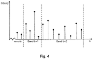
- the spectrum can be divided into frequency bands as shown in Fig. 4 .
- the number of frequency bands is typically in the order of 2-50 for the full audible bandwidth of 20 - 20000Hz.
- All frequency bands might have equal frequency-wise width, but more common in audio coding applications is to match the width of each frequency band to the human perception of audio, thus resulting in comparatively narrow frequency bands for the low frequencies and increasing widths of the frequency bands for higher frequencies.
- the spatial coherence is divided into frequency bands of non-equal lengths.
- the frequency bands can be created using the ERB-rate scale, where ERB is short for equivalent rectangular frequency bandwidth.
- the vector of spatial coherence values C m is then encoded to be stored or transmitted to a decoder of the receiving node 200b.
- the transmitting node 200a is configured to perform (optional) steps S102, S110a.
- the transmitting node 200a determines spectral characteristics of the audio signals on the input audio channels.
- the transmitting node 200a signals information about the spectral characteristics to the receiving node 200b.
- This information can e.g. be the filter coefficients obtained through Linear Prediction Analysis or the magnitude spectrum obtained through a Discrete Fourier Transform.
- Step S110a could be performed as part of step S110.
- the herein disclosed embodiments can be used to further enhance the intra-frame coding scheme. Therefore, according to an embodiment the first coherence prediction C ⁇ 1 , b , m q is defined by an intra-frame prediction C ⁇ intra , b , m q of the vector of spatial coherence values.
- the second prediction ⁇ 2,b,m is defined by an inter-frame coherence prediction ⁇ inter,b,m of the vector of spatial coherence values.
- the at least one reconstructed spatial coherence value is then formed based on a predicted spatial coherence value C ⁇ pred , b , m q .
- a balance can thereby be found between taking advantage of the inter-frame correlation of the spatial coherence whilst minimizing the risk of error propagation in case of frame loss.
- the value of the weight factor ⁇ used in the encoding has to, at least implicitly, be known in the decoder at the receiving node 200b. That is, information about the weight factor ⁇ has to be encoded and transmitted (as in step Sno) to the decoder at the receiving node 200b. Further aspects of how to provide the information about the weight factor ⁇ will be disclosed below.
- bit budget B m for frame m for encoding the spatial coherence is known in the decoder at the receiving node 200b without explicit signaling from the transmitting node 200a.
- the value of the bit budget B m is thus explicitly signalled to the receiving node 200b. It comes as a side effect, since the decoder at the receiving node 200b knows how to interpret the bitstream it also knows how many bits have been decoded. The remaining bits are simply found at the decoder at the receiving node 200b by subtracting the decoded number of bits from the total bit budget (which is also known).
- a set of candidate weight factors is selected and a trial encoding (without performing the rate-truncation strategy as disclosed below) with the combined prediction and residual encoding scheme is performed for all these candidate weight factors in order to find the total number of encoded bits, given the candidate weight factor used.
- the weight factor ⁇ is determined by selecting a set of at least two candidate weight factors and performing trial encoding of the vector of spatial coherence values for each candidate weight factor.
- which candidate weight factors to use during the trial encoding is based on the bit-budget B m .
- the candidate weight factors might be determined by means of performing a table lookup with the bit-budget B m as input or by inputting the bit-budget B m to a function.
- the table lookup might be performed on table values obtained through training on a set of background noise.
- the trial encoding for each candidate weight factor yields a respective total number of encoded bits for the vector of spatial coherence values.
- the weight factor ⁇ might then be selected depending on whether the total number of encoded bits for the candidate weight factors fits within the bit-budget B m or not. Particularly, according to an embodiment the weight factor ⁇ is selected as the largest candidate weight factor for which the total number of encoded bits fits within the bit-budget B m . According to an embodiment the weight factor ⁇ is selected as the candidate weight factor yielding fewest total number of encoded bits when the total number of encoded bits does not fit within the bit-budget B m for any of the candidate weight factors.
- the highest candidate weight factor is selected as the weight factor ⁇ .
- the candidate weight factor that leads to the lowest number of bits is selected as the weight factor ⁇ . Which of the candidate weight factor is selected is then signaled to the decoder at the receiving node 200b.
- the encoder at the transmitting node 200a receives a vector C m to encode, a memory of the last reconstructed vector ⁇ m- 1 , and a bit budget B m .
- Bits spent in preceding encoding steps may be included in B m and B curr,m . In that case the bit budget in the step outlined can be written as: B m - B curr.m .
- the first coefficient cannot rely on prediction from previous coefficients, it might, optionally, be desirable to encode this coefficient separately.
- the first coefficient might be encoded using a scalar quantizer to produce the reconstructed value ⁇ SQ ,1, m .
- C ⁇ intra , 1 , m q is given by an average value C ⁇ :
- C ⁇ intra , 1 , m q C ⁇ .
- two candidate weight factors ⁇ low and ⁇ high are obtained, either by means of performing a table lookup with the bit-budget B m as input or by inputting the bit-budget B m to a function.
- Trial encoding is performed without the rate-truncation strategy described below for each candidate weight factor ⁇ low and ⁇ high , yielding two values B currlow , m and B currhigh , m of the number of bits needed for the encoding.
- the selected weight factor ⁇ is encoded using one bit, e.g. "0" for ⁇ low and "1" for ⁇ high .
- the third alternative in the expression above for the weight factor ⁇ should be interpreted as follows: If both candidate weight factors ⁇ low and ⁇ high yield a resulting number of encoded bits that exceeds the bit budget B m , then the candidate weight factor yielding the lowest number of encoded bits is selected.
- the transmitting node 200a obtains an intra-frame prediction value C ⁇ intra , b , m q .
- the intra-frame prediction may thus be encoded as disclosed above.
- the transmitting node 200a obtains an inter-frame prediction value ⁇ inter , b , m based on previously reconstructed elements of the vector of spatial coherence values from one or more preceding frames.
- the prediction residual maybe quantized using a scalar quantizer and then encoded with a variable length code scheme such that fewer bits are consumed for smaller residuals.
- Some examples for encoding the residual are by means of Huffman coding, Golomb-Rice coding or a unary code (where the latter is the same as the Golomb-Rice coding with divisor 1).
- the remaining bit budget B m - B curr,m needs to be considered. If there are not sufficiently many remaining bits to encode the residual r b,m , a bit rate truncation strategy can be applied.
- One possible strategy is to encode the largest possible residual value, assuming that the smaller residual values cost fewer bits.
- Another strategy is to set the residual value to zero, which could be the most common prediction residual value and would be encoded with one bit.
- the transmitting node 200a is configured to perform (optional) steps S108, Snob.
- the transmitting node 200a determines a quantized prediction error per frame m and frequency band b by subtracting the at least one predicted spatial coherence value C ⁇ pred , b , m q from the vector of spatial coherence values.
- Snob The transmitting node 200a signals information about the quantized prediction error to the receiving node 200b.
- Step Snob could be performed as part of step S110.
- the residual might be set to zero without sending the index to the bitstream.
- the reconstructed spatial coherence value ⁇ b , m is similarly derived at the encoder where previously encoded coherence values ⁇ i,m are used in the intra-frame prediction for frame m, and previously reconstructed elements from one or more preceding frames are used in the inter-frame prediction, e.g. the last reconstructed value ⁇ b , m -1 for frequency band b.
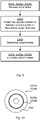
- Fig. 5 illustrating a method for generation of comfort noise for at least two audio channels at a receiving node 200b as performed by the receiving node 200b according to embodiments.
- the receiving node 200b is configured to reproduce the first and second prediction of the coherence value based on information obtained from the transmitting node 200a. In some aspects the receiving node 200b perform operations corresponding to those of the transmitting node 200a, starting with reception of necessary information.
- the receiving node 200b receives information about the weight factor ⁇ from the transmitting node 200a.
- the receiving node 200b This enables the receiving node 200b to reproduce the first and second prediction identical to the ones in the transmitting node 200a.
- the receiving node 200b then performs essentially the same steps as the transmitting node 200a.
- the receiving node 200b determines a spatial coherence between audio signals on the respective audio channels, wherein at least one predicted spatial coherence value C ⁇ pred , b , m q per frame m and frequency band b is determined to form a vector of predicted spatial coherence values, wherein the vector of predicted spatial coherence values is represented by a weighted combination of a first coherence prediction C ⁇ 1 , b , m q and a second coherence prediction ⁇ 2, b , m , wherein the first coherence prediction C ⁇ 1 , b , m q and the second coherence prediction ⁇ 2, b , m are combined using the weight factor ⁇ .
- the receiving node 200b determines the weight factor ⁇ based on a bit-budget B m available for encoding the vector of spatial coherence values in each frame and the received information.
- the receiving node 200b generates comfort noise for the at least two audio channels based on the weighted combination of the first coherence prediction C ⁇ 1 , b , m q and the second coherence prediction ⁇ 2,b,m .
- Embodiments relating to further details of generation of comfort noise for at least two audio channels at a receiving node 200b as performed by the receiving node 200b will now be disclosed.
- the embodiments as disclosed above with reference to the transmitting node 200a are also applicable to the receiving node 200b as modified where needed.
- the transmitting node 200a signals information about the spectral characteristics to the receiving node 200b. Therefore, according to an embodiment the receiving node 200b is configured to perform (optional) steps S202a and S208a:
- step S202a is performed as part of step S202 and step S208a is performed as part of step S202.
- the transmitting node 200a signals information about the quantized prediction error to the receiving node 200b. Therefore, according to an embodiment the receiving node 200b is configured to perform (optional) steps S202a and S208a:
- step S202b is performed as part of step S202 and step S208b is performed as part of step S202.
- the weight factor ⁇ is determined by selecting a set of at least two candidate weight factors and using the received information about the weight factor ⁇ to select which candidate weight factors to use during trial encoding.
- Fig. 6 schematically illustrates, in terms of a number of functional units, the components of a transmitting node 200a according to an embodiment.
- Processing circuitry 210 is provided using any combination of one or more of a suitable central processing unit (CPU), multiprocessor, microcontroller, digital signal processor (DSP), etc., capable of executing software instructions stored in a computer program product 1010a (as in Fig. 10 ), e.g. in the form of a storage medium 230.
- the processing circuitry 210 may further be provided as at least one application specific integrated circuit (ASIC), or field programmable gate array (FPGA).
- ASIC application specific integrated circuit
- FPGA field programmable gate array
- the processing circuitry 210 is configured to cause the transmitting node 200a to perform a set of operations, or steps, as disclosed above.
- the storage medium 230 may store the set of operations
- the processing circuitry 210 may be configured to retrieve the set of operations from the storage medium 230 to cause the transmitting node 200a to perform the set of operations.
- the set of operations may be provided as a set of executable instructions.
- the processing circuitry 210 is thereby arranged to execute methods as herein disclosed.
- the transmitting node 200a for supporting generation of comfort noise for at least two audio channels at a receiving node comprises a processing circuitry 210.
- the processing circuitry is configured to cause the transmitting node to determine a spatial coherence between audio signals on the respective audio channels, wherein at least one spatial coherence value C b , m per frame m and frequency band b is determined to form a vector of spatial coherence values.
- a vector of predicted spatial coherence values C ⁇ pred , b , m q is formed by a weighted combination of a first coherence prediction C ⁇ 1 , b , m q and a second coherence prediction ⁇ 2 ,b , m .
- the first coherence prediction C ⁇ 1 , b , m q and the second coherence prediction ⁇ 2,b,m are combined using a weight factor ⁇ .
- the weight factor ⁇ is determined based on a bit-budget B m available for encoding the vector of spatial coherence values in each frame m.
- the transmitting node is further caused to signal information about the weight factor ⁇ to the receiving node, for enabling the generation of the comfort noise for the at least two audio channels at the receiving node.
- the storage medium 230 may also comprise persistent storage, which, for example, can be any single one or combination of magnetic memory, optical memory, solid state memory or even remotely mounted memory.
- the transmitting node 200a may further comprise a communications interface 220 for communications with a receiving node 200b.
- the communications interface 220 may comprise one or more transmitters and receivers, comprising analogue and digital components.
- the processing circuitry 210 controls the general operation of the transmitting node 200a e.g. by sending data and control signals to the communications interface 220 and the storage medium 230, by receiving data and reports from the communications interface 220, and by retrieving data and instructions from the storage medium 230.
- Other components, as well as the related functionality, of the transmitting node 200a are omitted in order not to obscure the concepts presented herein.
- Fig. 7 schematically illustrates, in terms of a number of functional modules, the components of a transmitting node 200a according to an embodiment.
- the transmitting node 200a of Fig. 7 comprises a number of functional modules; a determine module 210a configured to perform step S102, a determine module 210b configured to perform step S104, a determine module 210c configured to perform step S106, a determine module 210d configured to perform step S108, and a signal module 210e configured to perform step Sno.
- the signal module 210e might further be configured to perform any of steps S110a and Snob.
- each functional module 210a-210e may be implemented in hardware or in software.
- one or more or all functional modules 210a-210e may be implemented by the processing circuitry 210, possibly in cooperation with the communications interface 220 and/or the storage medium 230.
- the processing circuitry 210 may thus be arranged to from the storage medium 230 fetch instructions as provided by a functional module 210a-210e and to execute these instructions, thereby performing any steps of the transmitting node 200a as disclosed herein.
- Fig. 8 schematically illustrates, in terms of a number of functional units, the components of a receiving node 200b according to an embodiment.
- Processing circuitry 410 is provided using any combination of one or more of a suitable central processing unit (CPU), multiprocessor, microcontroller, digital signal processor (DSP), etc., capable of executing software instructions stored in a computer program product 1010b (as in Fig. 10 ), e.g. in the form of a storage medium 430.
- the processing circuitry 410 may further be provided as at least one application specific integrated circuit (ASIC), or field programmable gate array (FPGA).
- ASIC application specific integrated circuit
- FPGA field programmable gate array
- the processing circuitry 410 is configured to cause the receiving node 200b to perform a set of operations, or steps, as disclosed above.
- the storage medium 430 may store the set of operations
- the processing circuitry 410 may be configured to retrieve the set of operations from the storage medium 430 to cause the receiving node 200b to perform the set of operations.
- the set of operations may be provided as a set of executable instructions.
- the processing circuitry 410 is thereby arranged to execute methods as herein disclosed.
- the receiving node 200b for generation of comfort noise for at least two audio channels at the receiving node comprises processing circuitry 410.
- the processing circuitry is configured to cause the receiving node to receive information about a weight factor ⁇ from the transmitting node, and to determine a spatial coherence between audio signals on the respective audio channels, wherein at least one predicted spatial coherence value C ⁇ pred , b , m q per frame m and frequency band b is determined to form a vector of predicted spatial coherence values.
- the vector of predicted spatial coherence values is represented by a weighted combination of a first coherence prediction C ⁇ 1 , b , m q and a second coherence prediction ⁇ 2, b , m , wherein the first coherence prediction C ⁇ 1 , b , m q and the second coherence prediction ⁇ 2, b , m are combined using the weight factor ⁇ .
- the weight factor ⁇ is determined based on a bit-budget B m available for encoding a vector of spatial coherence values in each frame and the received information.
- the receiving node is further caused to generate comfort noise for the at least two audio channels based on the weighted combination of the first coherence prediction C ⁇ 1 , b , m q and the second coherence prediction ⁇ 2,b,m .
- the storage medium 430 may also comprise persistent storage, which, for example, can be any single one or combination of magnetic memory, optical memory, solid state memory or even remotely mounted memory.
- the receiving node 200b may further comprise a communications interface 420 for communications with a transmitting node 200a.
- the communications interface 420 may comprise one or more transmitters and receivers, comprising analogue and digital components.
- the processing circuitry 410 controls the general operation of the receiving node 200b e.g. by sending data and control signals to the communications interface 420 and the storage medium 430, by receiving data and reports from the communications interface 420, and by retrieving data and instructions from the storage medium 430.
- Other components, as well as the related functionality, of the receiving node 200b are omitted in order not to obscure the concepts presented herein.
- Fig. 9 schematically illustrates, in terms of a number of functional modules, the components of a receiving node 200b according to an embodiment.
- the receiving node 200b of Fig. 9 comprises a number of functional modules; a receive module 410a configured to perform step S202, a determine module 410b configured to perform step S204, a determine module 410c configured to perform step S206, and a generate module 410d configured to perform step S208.
- the receive module 410a is further configured to perform any of steps S202a and S202b.
- the generate module 410d is further configured to perform any of steps S208a and S208b.
- the receiving node 200b of Fig. 9 may further comprise a number of optional functional modules.
- each functional module 410a-410d may be implemented in hardware or in software.
- one or more or all functional modules 410a-410d may be implemented by the processing circuitry 410, possibly in cooperation with the communications interface 420 and/or the storage medium 430.
- the processing circuitry 410 may thus be arranged to from the storage medium 430 fetch instructions as provided by a functional module 410a-410d and to execute these instructions, thereby performing any steps of the receiving node 200b as disclosed herein.
- the transmitting node 200a and/or the receiving node 200b may be provided as a standalone device or as a part of at least one further device.
- the transmitting node 200a is part of a radio transceiver device 200.
- a radio transceiver device 200 comprising a transmitting node 200a and/or a receiving node 200b as herein disclosed.
- functionality of the transmitting node 200a and/or the receiving node 200b may be distributed between at least two devices, or nodes. These at least two nodes, or devices, may either be part of the same network part or may be spread between at least two such network parts.
- a first portion of the instructions performed by the transmitting node 200a and/or the receiving node 200b may be executed in a first device
- a second portion of the of the instructions performed by the transmitting node 200a and/or the receiving node 200b may be executed in a second device; the herein disclosed embodiments are not limited to any particular number of devices on which the instructions performed by the transmitting node 200a and/or the receiving node 200b may be executed.
- the methods according to the herein disclosed embodiments are suitable to be performed by a transmitting node 200a and/or the receiving node 200b residing in a cloud computational environment. Therefore, although a single processing circuitry 210, 410 is illustrated in Figs. 6 and 8 the processing circuitry 210, 410 may be distributed among a plurality of devices, or nodes. The same applies to the functional modules 210a-210e, 410a-410d of Figs. 7 and 9 and the computer programs 1020a, 1020b of Fig. 10 (see below).
- Fig. 10 shows one example of a computer program product 1010a, 1010b comprising computer readable means 1030.
- a computer program 1020a can be stored, which computer program 1020a can cause the processing circuitry 210 and thereto operatively coupled entities and devices, such as the communications interface 220 and the storage medium 230, to execute methods according to embodiments described herein.
- the computer program 1020a and/or computer program product 1010a may thus provide means for performing any steps of the transmitting node 200a as herein disclosed.
- a computer program 1020b can be stored, which computer program 1020b can cause the processing circuitry 410 and thereto operatively coupled entities and devices, such as the communications interface 420 and the storage medium 430, to execute methods according to embodiments described herein.
- the computer program 1020b and/or computer program product 1010b may thus provide means for performing any steps of the receiving node 200b as herein disclosed.
- the computer program product 1010a, 1010b is illustrated as an optical disc, such as a CD (compact disc) or a DVD (digital versatile disc) or a Blu-Ray disc.
- the computer program product 1010a 1010b could also be embodied as a memory, such as a random access memory (RAM), a read-only memory (ROM), an erasable programmable read-only memory (EPROM), or an electrically erasable programmable read-only memory (EEPROM) and more particularly as a non-volatile storage medium of a device in an external memory such as a USB (Universal Serial Bus) memory or a Flash memory, such as a compact Flash memory.
- RAM random access memory
- ROM read-only memory
- EPROM erasable programmable read-only memory
- EEPROM electrically erasable programmable read-only memory
- the computer program 1020a, 1020b is here schematically shown as a track on the depicted optical disk, the computer program 1020a, 10
Landscapes
- Engineering & Computer Science (AREA)
- Physics & Mathematics (AREA)
- Human Computer Interaction (AREA)
- Signal Processing (AREA)
- Health & Medical Sciences (AREA)
- Audiology, Speech & Language Pathology (AREA)
- Computational Linguistics (AREA)
- Acoustics & Sound (AREA)
- Multimedia (AREA)
- Spectroscopy & Molecular Physics (AREA)
- Mathematical Physics (AREA)
- Quality & Reliability (AREA)
- Compression, Expansion, Code Conversion, And Decoders (AREA)
- Compression Or Coding Systems Of Tv Signals (AREA)
- Stereophonic System (AREA)
Priority Applications (2)
| Application Number | Priority Date | Filing Date | Title |
|---|---|---|---|
| EP23180564.9A EP4273858B1 (de) | 2018-04-05 | 2019-04-05 | Unterstützung zur erzeugung von komfortgeräuschen und erzeugung von komfortgeräuschen |
| EP25199508.0A EP4636757A2 (de) | 2018-04-05 | 2019-04-05 | Träger zur erzeugung von komfortgeräuschen und erzeugung von komfortgeräuschen |
Applications Claiming Priority (5)
| Application Number | Priority Date | Filing Date | Title |
|---|---|---|---|
| US201862652941P | 2018-04-05 | 2018-04-05 | |
| US201862652949P | 2018-04-05 | 2018-04-05 | |
| US201862653078P | 2018-04-05 | 2018-04-05 | |
| PCT/EP2019/058629 WO2019193149A1 (en) | 2018-04-05 | 2019-04-05 | Support for generation of comfort noise, and generation of comfort noise |
| EP19716874.3A EP3776546B1 (de) | 2018-04-05 | 2019-04-05 | Unterstützung zur erzeugung von komfortgeräuschen und erzeugung von komfortgeräuschen |
Related Parent Applications (1)
| Application Number | Title | Priority Date | Filing Date |
|---|---|---|---|
| EP19716874.3A Division EP3776546B1 (de) | 2018-04-05 | 2019-04-05 | Unterstützung zur erzeugung von komfortgeräuschen und erzeugung von komfortgeräuschen |
Related Child Applications (2)
| Application Number | Title | Priority Date | Filing Date |
|---|---|---|---|
| EP25199508.0A Division EP4636757A2 (de) | 2018-04-05 | 2019-04-05 | Träger zur erzeugung von komfortgeräuschen und erzeugung von komfortgeräuschen |
| EP23180564.9A Division EP4273858B1 (de) | 2018-04-05 | 2019-04-05 | Unterstützung zur erzeugung von komfortgeräuschen und erzeugung von komfortgeräuschen |
Publications (2)
| Publication Number | Publication Date |
|---|---|
| EP4047601A2 true EP4047601A2 (de) | 2022-08-24 |
| EP4047601A3 EP4047601A3 (de) | 2022-12-21 |
Family
ID=66102706
Family Applications (8)
| Application Number | Title | Priority Date | Filing Date |
|---|---|---|---|
| EP22151769.1A Withdrawn EP4047601A3 (de) | 2018-04-05 | 2019-04-05 | Träger zur erzeugung von komfortgeräuschen und erzeugung von komfortgeräuschen |
| EP25199508.0A Pending EP4636757A2 (de) | 2018-04-05 | 2019-04-05 | Träger zur erzeugung von komfortgeräuschen und erzeugung von komfortgeräuschen |
| EP25179846.8A Pending EP4586247A3 (de) | 2018-04-05 | 2019-04-05 | Beschneidbare prädiktive codierung |
| EP23180564.9A Active EP4273858B1 (de) | 2018-04-05 | 2019-04-05 | Unterstützung zur erzeugung von komfortgeräuschen und erzeugung von komfortgeräuschen |
| EP19717450.1A Active EP3776547B1 (de) | 2018-04-05 | 2019-04-05 | Unterstützung zur erzeugung von komfortgeräuschen |
| EP19716874.3A Active EP3776546B1 (de) | 2018-04-05 | 2019-04-05 | Unterstützung zur erzeugung von komfortgeräuschen und erzeugung von komfortgeräuschen |
| EP21185347.8A Pending EP3913626A1 (de) | 2018-04-05 | 2019-04-05 | Träger zur erzeugung von komfortgeräuschen |
| EP19717452.7A Active EP3776548B1 (de) | 2018-04-05 | 2019-04-05 | Kürzbare prädiktive codierung |
Family Applications After (7)
| Application Number | Title | Priority Date | Filing Date |
|---|---|---|---|
| EP25199508.0A Pending EP4636757A2 (de) | 2018-04-05 | 2019-04-05 | Träger zur erzeugung von komfortgeräuschen und erzeugung von komfortgeräuschen |
| EP25179846.8A Pending EP4586247A3 (de) | 2018-04-05 | 2019-04-05 | Beschneidbare prädiktive codierung |
| EP23180564.9A Active EP4273858B1 (de) | 2018-04-05 | 2019-04-05 | Unterstützung zur erzeugung von komfortgeräuschen und erzeugung von komfortgeräuschen |
| EP19717450.1A Active EP3776547B1 (de) | 2018-04-05 | 2019-04-05 | Unterstützung zur erzeugung von komfortgeräuschen |
| EP19716874.3A Active EP3776546B1 (de) | 2018-04-05 | 2019-04-05 | Unterstützung zur erzeugung von komfortgeräuschen und erzeugung von komfortgeräuschen |
| EP21185347.8A Pending EP3913626A1 (de) | 2018-04-05 | 2019-04-05 | Träger zur erzeugung von komfortgeräuschen |
| EP19717452.7A Active EP3776548B1 (de) | 2018-04-05 | 2019-04-05 | Kürzbare prädiktive codierung |
Country Status (8)
| Country | Link |
|---|---|
| US (10) | US11417348B2 (de) |
| EP (8) | EP4047601A3 (de) |
| JP (3) | JP7085640B2 (de) |
| KR (3) | KR102535034B1 (de) |
| CN (4) | CN118038881A (de) |
| DK (1) | DK3776547T3 (de) |
| MX (2) | MX2020010468A (de) |
| WO (3) | WO2019193149A1 (de) |
Cited By (1)
| Publication number | Priority date | Publication date | Assignee | Title |
|---|---|---|---|---|
| US20220291959A1 (en) * | 2021-06-03 | 2022-09-15 | Research Institute Of Physical And Chemical Engineering Of Nuclear Industry | Activity scheduling method, system, terminal and storage medium based on high response ratio |
Families Citing this family (14)
| Publication number | Priority date | Publication date | Assignee | Title |
|---|---|---|---|---|
| KR102535034B1 (ko) | 2018-04-05 | 2023-05-19 | 텔레폰악티에볼라겟엘엠에릭슨(펍) | 통신 소음 발생 및 통신 소음 발생을 위한 지원 |
| GB2592896A (en) * | 2020-01-13 | 2021-09-15 | Nokia Technologies Oy | Spatial audio parameter encoding and associated decoding |
| GB2595891A (en) * | 2020-06-10 | 2021-12-15 | Nokia Technologies Oy | Adapting multi-source inputs for constant rate encoding |
| KR20230023725A (ko) * | 2020-06-11 | 2023-02-17 | 돌비 레버러토리즈 라이쎈싱 코오포레이션 | 다중-채널 입력 신호 내의 공간 배경 잡음을 인코딩 및/또는 디코딩하기 위한 방법 및 디바이스 |
| GB2596138A (en) | 2020-06-19 | 2021-12-22 | Nokia Technologies Oy | Decoder spatial comfort noise generation for discontinuous transmission operation |
| CN117727310A (zh) * | 2020-07-07 | 2024-03-19 | 瑞典爱立信有限公司 | 多模式空间音频编码的舒适噪声生成 |
| ES3013669T3 (en) * | 2020-07-30 | 2025-04-14 | Fraunhofer Ges Forschung | Apparatus, method and computer program for encoding an audio scene |
| GB2598104A (en) * | 2020-08-17 | 2022-02-23 | Nokia Technologies Oy | Discontinuous transmission operation for spatial audio parameters |
| JP7584631B2 (ja) * | 2020-08-31 | 2024-11-15 | フラウンホファー ゲセルシャフト ツール フェールデルンク ダー アンゲヴァンテン フォルシュンク エー.ファオ. | ミキシングノイズ信号に依存する多チャネル信号発生器、オーディオエンコーダ、および関係する方法 |
| CN117223054A (zh) * | 2021-04-29 | 2023-12-12 | 沃伊斯亚吉公司 | 经解码的声音信号中的多声道舒适噪声注入的方法及设备 |
| WO2023031498A1 (en) * | 2021-08-30 | 2023-03-09 | Nokia Technologies Oy | Silence descriptor using spatial parameters |
| EP4449411B1 (de) | 2021-12-15 | 2025-10-22 | Telefonaktiebolaget LM Ericsson (publ) | Adaptive prädiktive kodierung |
| CN119895493A (zh) * | 2022-09-13 | 2025-04-25 | 瑞典爱立信有限公司 | 自适应声道间时间差估计 |
| AU2023355540A1 (en) | 2022-10-05 | 2025-02-20 | Telefonaktiebolaget Lm Ericsson (Publ) | Coherence calculation for stereo discontinuous transmission (dtx) |
Citations (1)
| Publication number | Priority date | Publication date | Assignee | Title |
|---|---|---|---|---|
| US20170047072A1 (en) | 2014-02-14 | 2017-02-16 | Telefonaktiebolaget Lm Ericsson (Publ) | Comfort noise generation |
Family Cites Families (38)
| Publication number | Priority date | Publication date | Assignee | Title |
|---|---|---|---|---|
| JPS6484300A (en) * | 1987-09-26 | 1989-03-29 | Fujitsu Ltd | Voice spectrum encoding system |
| US7920697B2 (en) | 1999-12-09 | 2011-04-05 | Broadcom Corp. | Interaction between echo canceller and packet voice processing |
| US7006636B2 (en) * | 2002-05-24 | 2006-02-28 | Agere Systems Inc. | Coherence-based audio coding and synthesis |
| RU2004118840A (ru) | 2001-11-23 | 2005-10-10 | Конинклейке Филипс Электроникс Н.В. (Nl) | Способ замещения воспринимаемого шума |
| US20040002856A1 (en) * | 2002-03-08 | 2004-01-01 | Udaya Bhaskar | Multi-rate frequency domain interpolative speech CODEC system |
| US20030187663A1 (en) * | 2002-03-28 | 2003-10-02 | Truman Michael Mead | Broadband frequency translation for high frequency regeneration |
| CA2388439A1 (en) * | 2002-05-31 | 2003-11-30 | Voiceage Corporation | A method and device for efficient frame erasure concealment in linear predictive based speech codecs |
| CN1458646A (zh) * | 2003-04-21 | 2003-11-26 | 北京阜国数字技术有限公司 | 一种滤波参数矢量量化和结合量化模型预测的音频编码方法 |
| CN1677493A (zh) * | 2004-04-01 | 2005-10-05 | 北京宫羽数字技术有限责任公司 | 一种增强音频编解码装置及方法 |
| CN1677491A (zh) * | 2004-04-01 | 2005-10-05 | 北京宫羽数字技术有限责任公司 | 一种增强音频编解码装置及方法 |
| WO2006048815A1 (en) | 2004-11-04 | 2006-05-11 | Koninklijke Philips Electronics N.V. | Encoding and decoding a set of signals |
| EP2039171B1 (de) * | 2006-07-07 | 2016-10-05 | Telefonaktiebolaget LM Ericsson (publ) | Gewichtete prädiktion für videokodierung |
| EP3591650B1 (de) * | 2007-08-27 | 2020-12-23 | Telefonaktiebolaget LM Ericsson (publ) | Verfahren und vorrichtung zum füllen spektraler löcher |
| KR101629862B1 (ko) * | 2008-05-23 | 2016-06-24 | 코닌클리케 필립스 엔.브이. | 파라메트릭 스테레오 업믹스 장치, 파라메트릭 스테레오 디코더, 파라메트릭 스테레오 다운믹스 장치, 파라메트릭 스테레오 인코더 |
| JP5608660B2 (ja) * | 2008-10-10 | 2014-10-15 | テレフオンアクチーボラゲット エル エム エリクソン(パブル) | エネルギ保存型マルチチャネルオーディオ符号化 |
| ES2435792T3 (es) * | 2008-12-15 | 2013-12-23 | Orange | Codificación perfeccionada de señales digitales de audio multicanal |
| US20120230405A1 (en) * | 2009-10-28 | 2012-09-13 | Media Tek Singapore Pte. Ltd. | Video coding methods and video encoders and decoders with localized weighted prediction |
| KR101690252B1 (ko) * | 2009-12-23 | 2016-12-27 | 삼성전자주식회사 | 신호 처리 방법 및 장치 |
| US20130197919A1 (en) * | 2010-01-22 | 2013-08-01 | Agency For Science, Technology And Research | "method and device for determining a number of bits for encoding an audio signal" |
| US8924222B2 (en) * | 2010-07-30 | 2014-12-30 | Qualcomm Incorporated | Systems, methods, apparatus, and computer-readable media for coding of harmonic signals |
| HUE026874T2 (en) | 2011-03-10 | 2016-07-28 | ERICSSON TELEFON AB L M (publ) | Filling of non-coded sub-vectors in transform coded audio signals |
| TR201900411T4 (tr) | 2011-04-05 | 2019-02-21 | Nippon Telegraph & Telephone | Akustik sinyal kodu çözme. |
| EP2813079B1 (de) * | 2012-06-20 | 2019-08-07 | HFI Innovation Inc. | Verfahren und vorrichtung zur inter-schicht prädiktion zur skalierbaren videocodierung |
| US9906786B2 (en) * | 2012-09-07 | 2018-02-27 | Qualcomm Incorporated | Weighted prediction mode for scalable video coding |
| US9456286B2 (en) * | 2012-09-28 | 2016-09-27 | Sonova Ag | Method for operating a binaural hearing system and binaural hearing system |
| EP3525208B1 (de) * | 2012-10-01 | 2021-07-28 | Nippon Telegraph and Telephone Corporation | Codierungsverfahren, codierer, programm und aufzeichnungsmedium |
| US9318092B2 (en) * | 2013-01-29 | 2016-04-19 | 2236008 Ontario Inc. | Noise estimation control system |
| CN104050969A (zh) * | 2013-03-14 | 2014-09-17 | 杜比实验室特许公司 | 空间舒适噪声 |
| EP2976768A4 (de) * | 2013-03-20 | 2016-11-09 | Nokia Technologies Oy | Audiosignalcodierer mit einem mehrkanalparameterwähler |
| GB2515593B (en) | 2013-12-23 | 2015-12-23 | Imagination Tech Ltd | Acoustic echo suppression |
| CN104978970B (zh) * | 2014-04-08 | 2019-02-12 | 华为技术有限公司 | 一种噪声信号的处理和生成方法、编解码器和编解码系统 |
| EP2980793A1 (de) * | 2014-07-28 | 2016-02-03 | Fraunhofer-Gesellschaft zur Förderung der angewandten Forschung e.V. | Codierer, Decodierer, System und Verfahren zur Codierung und Decodierung |
| US10366698B2 (en) * | 2016-08-30 | 2019-07-30 | Dts, Inc. | Variable length coding of indices and bit scheduling in a pyramid vector quantizer |
| US9865274B1 (en) | 2016-12-22 | 2018-01-09 | Getgo, Inc. | Ambisonic audio signal processing for bidirectional real-time communication |
| US10367948B2 (en) * | 2017-01-13 | 2019-07-30 | Shure Acquisition Holdings, Inc. | Post-mixing acoustic echo cancellation systems and methods |
| US10170134B2 (en) | 2017-02-21 | 2019-01-01 | Intel IP Corporation | Method and system of acoustic dereverberation factoring the actual non-ideal acoustic environment |
| KR102535034B1 (ko) | 2018-04-05 | 2023-05-19 | 텔레폰악티에볼라겟엘엠에릭슨(펍) | 통신 소음 발생 및 통신 소음 발생을 위한 지원 |
| US11025951B2 (en) * | 2019-01-13 | 2021-06-01 | Tencent America LLC | Method and apparatus for video coding |
-
2019
- 2019-04-05 KR KR1020207031390A patent/KR102535034B1/ko active Active
- 2019-04-05 KR KR1020237013683A patent/KR102675420B1/ko active Active
- 2019-04-05 KR KR1020207031954A patent/KR102548184B1/ko active Active
- 2019-04-05 EP EP22151769.1A patent/EP4047601A3/de not_active Withdrawn
- 2019-04-05 EP EP25199508.0A patent/EP4636757A2/de active Pending
- 2019-04-05 US US17/044,732 patent/US11417348B2/en active Active
- 2019-04-05 EP EP25179846.8A patent/EP4586247A3/de active Pending
- 2019-04-05 EP EP23180564.9A patent/EP4273858B1/de active Active
- 2019-04-05 CN CN202410257919.2A patent/CN118038881A/zh active Pending
- 2019-04-05 WO PCT/EP2019/058629 patent/WO2019193149A1/en not_active Ceased
- 2019-04-05 CN CN201980034376.5A patent/CN112154502B/zh active Active
- 2019-04-05 EP EP19717450.1A patent/EP3776547B1/de active Active
- 2019-04-05 WO PCT/EP2019/058650 patent/WO2019193156A1/en not_active Ceased
- 2019-04-05 EP EP19716874.3A patent/EP3776546B1/de active Active
- 2019-04-05 WO PCT/EP2019/058681 patent/WO2019193173A1/en not_active Ceased
- 2019-04-05 MX MX2020010468A patent/MX2020010468A/es unknown
- 2019-04-05 US US17/045,103 patent/US11404069B2/en active Active
- 2019-04-05 CN CN201980031508.9A patent/CN112119457B/zh active Active
- 2019-04-05 US US17/044,740 patent/US11495237B2/en active Active
- 2019-04-05 CN CN202411460314.XA patent/CN119314496A/zh active Pending
- 2019-04-05 DK DK19717450.1T patent/DK3776547T3/da active
- 2019-04-05 EP EP21185347.8A patent/EP3913626A1/de active Pending
- 2019-04-05 JP JP2020554191A patent/JP7085640B2/ja active Active
- 2019-04-05 EP EP19717452.7A patent/EP3776548B1/de active Active
-
2020
- 2020-10-02 MX MX2024002833A patent/MX2024002833A/es unknown
-
2022
- 2022-06-06 JP JP2022091269A patent/JP7438268B2/ja active Active
- 2022-06-21 US US17/844,803 patent/US11837242B2/en active Active
- 2022-08-03 US US17/817,251 patent/US11978460B2/en active Active
- 2022-11-03 US US17/980,386 patent/US11862181B2/en active Active
-
2023
- 2023-10-26 US US18/383,953 patent/US20240055008A1/en active Pending
- 2023-11-21 US US18/516,046 patent/US12327568B2/en active Active
-
2024
- 2024-02-13 JP JP2024019342A patent/JP7746431B2/ja active Active
- 2024-04-23 US US18/643,227 patent/US12469504B2/en active Active
-
2025
- 2025-03-25 US US19/089,233 patent/US20250285628A1/en active Pending
Patent Citations (1)
| Publication number | Priority date | Publication date | Assignee | Title |
|---|---|---|---|---|
| US20170047072A1 (en) | 2014-02-14 | 2017-02-16 | Telefonaktiebolaget Lm Ericsson (Publ) | Comfort noise generation |
Cited By (1)
| Publication number | Priority date | Publication date | Assignee | Title |
|---|---|---|---|---|
| US20220291959A1 (en) * | 2021-06-03 | 2022-09-15 | Research Institute Of Physical And Chemical Engineering Of Nuclear Industry | Activity scheduling method, system, terminal and storage medium based on high response ratio |
Also Published As
Similar Documents
| Publication | Publication Date | Title |
|---|---|---|
| EP3776546B1 (de) | Unterstützung zur erzeugung von komfortgeräuschen und erzeugung von komfortgeräuschen |
Legal Events
| Date | Code | Title | Description |
|---|---|---|---|
| PUAI | Public reference made under article 153(3) epc to a published international application that has entered the european phase |
Free format text: ORIGINAL CODE: 0009012 |
|
| STAA | Information on the status of an ep patent application or granted ep patent |
Free format text: STATUS: THE APPLICATION HAS BEEN PUBLISHED |
|
| AC | Divisional application: reference to earlier application |
Ref document number: 3776546 Country of ref document: EP Kind code of ref document: P |
|
| AK | Designated contracting states |
Kind code of ref document: A2 Designated state(s): AL AT BE BG CH CY CZ DE DK EE ES FI FR GB GR HR HU IE IS IT LI LT LU LV MC MK MT NL NO PL PT RO RS SE SI SK SM TR |
|
| PUAL | Search report despatched |
Free format text: ORIGINAL CODE: 0009013 |
|
| AK | Designated contracting states |
Kind code of ref document: A3 Designated state(s): AL AT BE BG CH CY CZ DE DK EE ES FI FR GB GR HR HU IE IS IT LI LT LU LV MC MK MT NL NO PL PT RO RS SE SI SK SM TR |
|
| RIC1 | Information provided on ipc code assigned before grant |
Ipc: G10L 19/24 20130101ALN20221114BHEP Ipc: G10L 19/03 20130101ALN20221114BHEP Ipc: G10L 19/008 20130101ALN20221114BHEP Ipc: G10L 19/04 20130101ALI20221114BHEP Ipc: G10L 19/012 20130101AFI20221114BHEP |
|
| STAA | Information on the status of an ep patent application or granted ep patent |
Free format text: STATUS: THE APPLICATION IS DEEMED TO BE WITHDRAWN |
|
| 18D | Application deemed to be withdrawn |
Effective date: 20230622 |