EP4047515B1 - Plattform zur entwicklung eines wahrnehmungssystems für automatisierte antriebssysteme - Google Patents
Plattform zur entwicklung eines wahrnehmungssystems für automatisierte antriebssysteme Download PDFInfo
- Publication number
- EP4047515B1 EP4047515B1 EP21158017.0A EP21158017A EP4047515B1 EP 4047515 B1 EP4047515 B1 EP 4047515B1 EP 21158017 A EP21158017 A EP 21158017A EP 4047515 B1 EP4047515 B1 EP 4047515B1
- Authority
- EP
- European Patent Office
- Prior art keywords
- perception
- vehicle
- data
- baseline
- perceptive
- Prior art date
- Legal status (The legal status is an assumption and is not a legal conclusion. Google has not performed a legal analysis and makes no representation as to the accuracy of the status listed.)
- Active
Links
Images


Classifications
-
- B—PERFORMING OPERATIONS; TRANSPORTING
- B60—VEHICLES IN GENERAL
- B60W—CONJOINT CONTROL OF VEHICLE SUB-UNITS OF DIFFERENT TYPE OR DIFFERENT FUNCTION; CONTROL SYSTEMS SPECIALLY ADAPTED FOR HYBRID VEHICLES; ROAD VEHICLE DRIVE CONTROL SYSTEMS FOR PURPOSES NOT RELATED TO THE CONTROL OF A PARTICULAR SUB-UNIT
- B60W60/00—Drive control systems specially adapted for autonomous road vehicles
- B60W60/001—Planning or execution of driving tasks
-
- G—PHYSICS
- G06—COMPUTING OR CALCULATING; COUNTING
- G06V—IMAGE OR VIDEO RECOGNITION OR UNDERSTANDING
- G06V20/00—Scenes; Scene-specific elements
- G06V20/50—Context or environment of the image
- G06V20/56—Context or environment of the image exterior to a vehicle by using sensors mounted on the vehicle
- G06V20/58—Recognition of moving objects or obstacles, e.g. vehicles or pedestrians; Recognition of traffic objects, e.g. traffic signs, traffic lights or roads
-
- G—PHYSICS
- G06—COMPUTING OR CALCULATING; COUNTING
- G06F—ELECTRIC DIGITAL DATA PROCESSING
- G06F8/00—Arrangements for software engineering
- G06F8/20—Software design
-
- G—PHYSICS
- G01—MEASURING; TESTING
- G01S—RADIO DIRECTION-FINDING; RADIO NAVIGATION; DETERMINING DISTANCE OR VELOCITY BY USE OF RADIO WAVES; LOCATING OR PRESENCE-DETECTING BY USE OF THE REFLECTION OR RERADIATION OF RADIO WAVES; ANALOGOUS ARRANGEMENTS USING OTHER WAVES
- G01S13/00—Systems using the reflection or reradiation of radio waves, e.g. radar systems; Analogous systems using reflection or reradiation of waves whose nature or wavelength is irrelevant or unspecified
- G01S13/86—Combinations of radar systems with non-radar systems, e.g. sonar, direction finder
- G01S13/865—Combination of radar systems with lidar systems
-
- G—PHYSICS
- G01—MEASURING; TESTING
- G01S—RADIO DIRECTION-FINDING; RADIO NAVIGATION; DETERMINING DISTANCE OR VELOCITY BY USE OF RADIO WAVES; LOCATING OR PRESENCE-DETECTING BY USE OF THE REFLECTION OR RERADIATION OF RADIO WAVES; ANALOGOUS ARRANGEMENTS USING OTHER WAVES
- G01S13/00—Systems using the reflection or reradiation of radio waves, e.g. radar systems; Analogous systems using reflection or reradiation of waves whose nature or wavelength is irrelevant or unspecified
- G01S13/86—Combinations of radar systems with non-radar systems, e.g. sonar, direction finder
- G01S13/867—Combination of radar systems with cameras
-
- G—PHYSICS
- G01—MEASURING; TESTING
- G01S—RADIO DIRECTION-FINDING; RADIO NAVIGATION; DETERMINING DISTANCE OR VELOCITY BY USE OF RADIO WAVES; LOCATING OR PRESENCE-DETECTING BY USE OF THE REFLECTION OR RERADIATION OF RADIO WAVES; ANALOGOUS ARRANGEMENTS USING OTHER WAVES
- G01S13/00—Systems using the reflection or reradiation of radio waves, e.g. radar systems; Analogous systems using reflection or reradiation of waves whose nature or wavelength is irrelevant or unspecified
- G01S13/87—Combinations of radar systems, e.g. primary radar and secondary radar
-
- G—PHYSICS
- G01—MEASURING; TESTING
- G01S—RADIO DIRECTION-FINDING; RADIO NAVIGATION; DETERMINING DISTANCE OR VELOCITY BY USE OF RADIO WAVES; LOCATING OR PRESENCE-DETECTING BY USE OF THE REFLECTION OR RERADIATION OF RADIO WAVES; ANALOGOUS ARRANGEMENTS USING OTHER WAVES
- G01S13/00—Systems using the reflection or reradiation of radio waves, e.g. radar systems; Analogous systems using reflection or reradiation of waves whose nature or wavelength is irrelevant or unspecified
- G01S13/88—Radar or analogous systems specially adapted for specific applications
- G01S13/93—Radar or analogous systems specially adapted for specific applications for anti-collision purposes
- G01S13/931—Radar or analogous systems specially adapted for specific applications for anti-collision purposes of land vehicles
-
- G—PHYSICS
- G01—MEASURING; TESTING
- G01S—RADIO DIRECTION-FINDING; RADIO NAVIGATION; DETERMINING DISTANCE OR VELOCITY BY USE OF RADIO WAVES; LOCATING OR PRESENCE-DETECTING BY USE OF THE REFLECTION OR RERADIATION OF RADIO WAVES; ANALOGOUS ARRANGEMENTS USING OTHER WAVES
- G01S17/00—Systems using the reflection or reradiation of electromagnetic waves other than radio waves, e.g. lidar systems
- G01S17/86—Combinations of lidar systems with systems other than lidar, radar or sonar, e.g. with direction finders
-
- G—PHYSICS
- G01—MEASURING; TESTING
- G01S—RADIO DIRECTION-FINDING; RADIO NAVIGATION; DETERMINING DISTANCE OR VELOCITY BY USE OF RADIO WAVES; LOCATING OR PRESENCE-DETECTING BY USE OF THE REFLECTION OR RERADIATION OF RADIO WAVES; ANALOGOUS ARRANGEMENTS USING OTHER WAVES
- G01S17/00—Systems using the reflection or reradiation of electromagnetic waves other than radio waves, e.g. lidar systems
- G01S17/87—Combinations of systems using electromagnetic waves other than radio waves
-
- G—PHYSICS
- G01—MEASURING; TESTING
- G01S—RADIO DIRECTION-FINDING; RADIO NAVIGATION; DETERMINING DISTANCE OR VELOCITY BY USE OF RADIO WAVES; LOCATING OR PRESENCE-DETECTING BY USE OF THE REFLECTION OR RERADIATION OF RADIO WAVES; ANALOGOUS ARRANGEMENTS USING OTHER WAVES
- G01S17/00—Systems using the reflection or reradiation of electromagnetic waves other than radio waves, e.g. lidar systems
- G01S17/88—Lidar systems specially adapted for specific applications
- G01S17/93—Lidar systems specially adapted for specific applications for anti-collision purposes
- G01S17/931—Lidar systems specially adapted for specific applications for anti-collision purposes of land vehicles
-
- G—PHYSICS
- G06—COMPUTING OR CALCULATING; COUNTING
- G06F—ELECTRIC DIGITAL DATA PROCESSING
- G06F18/00—Pattern recognition
- G06F18/20—Analysing
- G06F18/21—Design or setup of recognition systems or techniques; Extraction of features in feature space; Blind source separation
- G06F18/217—Validation; Performance evaluation; Active pattern learning techniques
-
- G—PHYSICS
- G06—COMPUTING OR CALCULATING; COUNTING
- G06F—ELECTRIC DIGITAL DATA PROCESSING
- G06F8/00—Arrangements for software engineering
- G06F8/70—Software maintenance or management
- G06F8/73—Program documentation
-
- G—PHYSICS
- G06—COMPUTING OR CALCULATING; COUNTING
- G06Q—INFORMATION AND COMMUNICATION TECHNOLOGY [ICT] SPECIALLY ADAPTED FOR ADMINISTRATIVE, COMMERCIAL, FINANCIAL, MANAGERIAL OR SUPERVISORY PURPOSES; SYSTEMS OR METHODS SPECIALLY ADAPTED FOR ADMINISTRATIVE, COMMERCIAL, FINANCIAL, MANAGERIAL OR SUPERVISORY PURPOSES, NOT OTHERWISE PROVIDED FOR
- G06Q50/00—Information and communication technology [ICT] specially adapted for implementation of business processes of specific business sectors, e.g. utilities or tourism
- G06Q50/40—Business processes related to the transportation industry
-
- G—PHYSICS
- G06—COMPUTING OR CALCULATING; COUNTING
- G06V—IMAGE OR VIDEO RECOGNITION OR UNDERSTANDING
- G06V10/00—Arrangements for image or video recognition or understanding
- G06V10/70—Arrangements for image or video recognition or understanding using pattern recognition or machine learning
- G06V10/74—Image or video pattern matching; Proximity measures in feature spaces
-
- G—PHYSICS
- G06—COMPUTING OR CALCULATING; COUNTING
- G06V—IMAGE OR VIDEO RECOGNITION OR UNDERSTANDING
- G06V10/00—Arrangements for image or video recognition or understanding
- G06V10/70—Arrangements for image or video recognition or understanding using pattern recognition or machine learning
- G06V10/764—Arrangements for image or video recognition or understanding using pattern recognition or machine learning using classification, e.g. of video objects
-
- G—PHYSICS
- G06—COMPUTING OR CALCULATING; COUNTING
- G06V—IMAGE OR VIDEO RECOGNITION OR UNDERSTANDING
- G06V10/00—Arrangements for image or video recognition or understanding
- G06V10/70—Arrangements for image or video recognition or understanding using pattern recognition or machine learning
- G06V10/77—Processing image or video features in feature spaces; using data integration or data reduction, e.g. principal component analysis [PCA] or independent component analysis [ICA] or self-organising maps [SOM]; Blind source separation
- G06V10/80—Fusion, i.e. combining data from various sources at the sensor level, preprocessing level, feature extraction level or classification level
- G06V10/803—Fusion, i.e. combining data from various sources at the sensor level, preprocessing level, feature extraction level or classification level of input or preprocessed data
-
- G—PHYSICS
- G06—COMPUTING OR CALCULATING; COUNTING
- G06V—IMAGE OR VIDEO RECOGNITION OR UNDERSTANDING
- G06V20/00—Scenes; Scene-specific elements
- G06V20/50—Context or environment of the image
- G06V20/56—Context or environment of the image exterior to a vehicle by using sensors mounted on the vehicle
- G06V20/588—Recognition of the road, e.g. of lane markings; Recognition of the vehicle driving pattern in relation to the road
-
- B—PERFORMING OPERATIONS; TRANSPORTING
- B60—VEHICLES IN GENERAL
- B60W—CONJOINT CONTROL OF VEHICLE SUB-UNITS OF DIFFERENT TYPE OR DIFFERENT FUNCTION; CONTROL SYSTEMS SPECIALLY ADAPTED FOR HYBRID VEHICLES; ROAD VEHICLE DRIVE CONTROL SYSTEMS FOR PURPOSES NOT RELATED TO THE CONTROL OF A PARTICULAR SUB-UNIT
- B60W2555/00—Input parameters relating to exterior conditions, not covered by groups B60W2552/00, B60W2554/00
-
- G—PHYSICS
- G01—MEASURING; TESTING
- G01S—RADIO DIRECTION-FINDING; RADIO NAVIGATION; DETERMINING DISTANCE OR VELOCITY BY USE OF RADIO WAVES; LOCATING OR PRESENCE-DETECTING BY USE OF THE REFLECTION OR RERADIATION OF RADIO WAVES; ANALOGOUS ARRANGEMENTS USING OTHER WAVES
- G01S15/00—Systems using the reflection or reradiation of acoustic waves, e.g. sonar systems
- G01S15/86—Combinations of sonar systems with lidar systems; Combinations of sonar systems with systems not using wave reflection
-
- G—PHYSICS
- G01—MEASURING; TESTING
- G01S—RADIO DIRECTION-FINDING; RADIO NAVIGATION; DETERMINING DISTANCE OR VELOCITY BY USE OF RADIO WAVES; LOCATING OR PRESENCE-DETECTING BY USE OF THE REFLECTION OR RERADIATION OF RADIO WAVES; ANALOGOUS ARRANGEMENTS USING OTHER WAVES
- G01S15/00—Systems using the reflection or reradiation of acoustic waves, e.g. sonar systems
- G01S15/87—Combinations of sonar systems
-
- G—PHYSICS
- G01—MEASURING; TESTING
- G01S—RADIO DIRECTION-FINDING; RADIO NAVIGATION; DETERMINING DISTANCE OR VELOCITY BY USE OF RADIO WAVES; LOCATING OR PRESENCE-DETECTING BY USE OF THE REFLECTION OR RERADIATION OF RADIO WAVES; ANALOGOUS ARRANGEMENTS USING OTHER WAVES
- G01S15/00—Systems using the reflection or reradiation of acoustic waves, e.g. sonar systems
- G01S15/88—Sonar systems specially adapted for specific applications
- G01S15/93—Sonar systems specially adapted for specific applications for anti-collision purposes
- G01S15/931—Sonar systems specially adapted for specific applications for anti-collision purposes of land vehicles
-
- G—PHYSICS
- G01—MEASURING; TESTING
- G01S—RADIO DIRECTION-FINDING; RADIO NAVIGATION; DETERMINING DISTANCE OR VELOCITY BY USE OF RADIO WAVES; LOCATING OR PRESENCE-DETECTING BY USE OF THE REFLECTION OR RERADIATION OF RADIO WAVES; ANALOGOUS ARRANGEMENTS USING OTHER WAVES
- G01S13/00—Systems using the reflection or reradiation of radio waves, e.g. radar systems; Analogous systems using reflection or reradiation of waves whose nature or wavelength is irrelevant or unspecified
- G01S13/88—Radar or analogous systems specially adapted for specific applications
- G01S13/93—Radar or analogous systems specially adapted for specific applications for anti-collision purposes
- G01S13/931—Radar or analogous systems specially adapted for specific applications for anti-collision purposes of land vehicles
- G01S2013/9323—Alternative operation using light waves
-
- G—PHYSICS
- G01—MEASURING; TESTING
- G01S—RADIO DIRECTION-FINDING; RADIO NAVIGATION; DETERMINING DISTANCE OR VELOCITY BY USE OF RADIO WAVES; LOCATING OR PRESENCE-DETECTING BY USE OF THE REFLECTION OR RERADIATION OF RADIO WAVES; ANALOGOUS ARRANGEMENTS USING OTHER WAVES
- G01S13/00—Systems using the reflection or reradiation of radio waves, e.g. radar systems; Analogous systems using reflection or reradiation of waves whose nature or wavelength is irrelevant or unspecified
- G01S13/88—Radar or analogous systems specially adapted for specific applications
- G01S13/93—Radar or analogous systems specially adapted for specific applications for anti-collision purposes
- G01S13/931—Radar or analogous systems specially adapted for specific applications for anti-collision purposes of land vehicles
- G01S2013/9324—Alternative operation using ultrasonic waves
Definitions
- the present disclosure relates to methods and systems for performance evaluation and updating of a perception-development module of a vehicle equipped with an Automated Driving System (ADS).
- ADS Automated Driving System
- ADAS driver-assistance systems
- AD Autonomous Driving
- ADAS and AD will herein be referred to under the common term Automated Driving System (ADS) corresponding to all of the different levels of automation as for example defined by the SAE J3016 levels (0 - 5) of driving automation, and in particular for level 4 and 5.
- ADS Automated Driving System
- An ADS may be construed as a complex combination of various components that can be defined as systems where perception, decision making, and operation of the vehicle are performed by electronics and machinery instead of a human driver, and as introduction of automation into road traffic. This includes handling of the vehicle, destination, as well as awareness of surroundings. While the automated system has control over the vehicle, it allows the human operator to leave all or at least some responsibilities to the system.
- An ADS commonly combines a variety of sensors to perceive the vehicle's surroundings, such as e.g. radar, LIDAR, sonar, camera, navigation system e.g. GPS, odometer and/or inertial measurement units (IMUs), upon which advanced control systems may interpret sensory information to identify appropriate navigation paths, as well as obstacles, free-space areas, and/or relevant signage.
- WO 2020/056331 is for a method for crowd-sourced collection of large amounts of training data to be used for improving the perception algorithm of Advanced Driver-Assistance Systems (ADAS) and Autonomous Driving (AD) systems.
- ADAS Advanced Driver-Assistance Systems
- AD Autonomous Driving
- WO2020/079698 is for a method for systematic testing of an ADAS, it involves comparing concurrent sensor data from different sensors within a region of interest (ROI) to determine possible anomalies.
- ROI region of interest
- WO 2019/232335 is for method for continuos training of ADAS and AD systems. It involves an iterative training of the models based on previously encountered labelled scenarios and newly encountered ones. It further foresees automatic labelling of newly encountered scenarios to alleviate the burden of manual annotation.
- US 2020/210778 is for a method for generating training data for re-training an object-detecting Neural Network (ODNN) of an ADAS and AD systems.
- ODNN object-detecting Neural Network
- a certain object is detected in two separate images and a similarity value is computed. When this value is below a threshold one of the images is sent to a central entity for human labelling.
- a method performed by a computing system for performance evaluation of a perception-development module (i.e. a perception module under development) of a vehicle, where the vehicle is equipped with an ADS.
- the method comprises storing, during a time period, a first set of perception data obtained from a perception module of the vehicle.
- the perception module is configured to generate the first set of perception data based on sensor data obtained from one or more vehicle-mounted sensors during the time period.
- the method further comprises forming, by post-processing the first set of perception data, a baseline worldview (i.e. a baseline perception output) indicative of a scenario in the surrounding environment of the vehicle during the time period.
- a baseline worldview i.e. a baseline perception output
- the method further comprises obtaining a second set of perception data from the perception-development module.
- the perception-development module is configured to generate the second set of perception data based on a perception model and sensor data obtained from one or more vehicle-mounted sensors during the time period.
- the second set of perception data is indicative of a perceptive parameter of the surrounding environment of the vehicle during the time period.
- the method comprises matching the second set of perception data to the formed baseline worldview in order to identify a match between the perceptive parameter of the second set of perception data and a corresponding perceptive parameter in the baseline worldview.
- the method further comprises evaluating the obtained second set of perception data in reference to the baseline worldview in order to determine a cost function indicative of a performance of the perception-development module.
- the cost function is determined based on the identified match between the perceptive parameter of the second set of perception data and a corresponding perceptive parameter in the baseline worldview. Further, the method comprises updating one or more parameters of the perception model of the perception-development module by means of an optimization algorithm configured to minimize the calculated cost function.
- a (non-transitory) computer-readable storage medium storing one or more programs configured to be executed by one or more processors of an in-vehicle processing system, the one or more programs comprising instructions for performing the method according to any one of the embodiments disclosed herein.
- non-transitory is intended to describe a computer-readable storage medium (or “memory”) excluding propagating electromagnetic signals, but are not intended to otherwise limit the type of physical computer-readable storage device that is encompassed by the phrase computer-readable medium or memory.
- the terms “non-transitory computer readable medium” or “tangible memory” are intended to encompass types of storage devices that do not necessarily store information permanently, including for example, random access memory (RAM).
- Program instructions and data stored on a tangible computer-accessible storage medium in non-transitory form may further be transmitted by transmission media or signals such as electrical, electromagnetic, or digital signals, which may be conveyed via a communication medium such as a network and/or a wireless link.
- the term “non-transitory”, as used herein is a limitation of the medium itself (i.e., tangible, not a signal) as opposed to a limitation on data storage persistency (e.g., RAM vs. ROM).
- a system for performance evaluation of a perception-development module of an ADS-equipped vehicle comprising control circuitry configured to store, during a time period, a first set of perception data obtained from the perception module of the vehicle.
- the perception module is configured to generate the first set of perception data based on sensor data obtained from one or more vehicle-mounted sensors during the time period.
- the control circuitry is configured to form, by post-processing the first set of perception data, a baseline worldview indicative of a scenario in the surrounding environment of the vehicle during the time period.
- the control circuitry is further configured to obtain a second set of perception data from the perception-development module, where the perception-development module is configured to generate the second set of perception data based on a perception model and sensor data obtained from one or more vehicle-mounted sensors during the time period.
- the second set of perception data is indicative of a perceptive parameter of the surrounding environment of the vehicle during the time period.
- the control circuitry is configured to match the second set of perception data to the formed baseline worldview in order to identify a match between the perceptive parameter of the second set of perception data and a corresponding perceptive parameter in the baseline worldview.
- control circuitry is configured to evaluate the obtained second set of perception data in reference to the baseline worldview in order to determine a cost function indicative of a performance of the perception-development module based on the identified match between the perceptive parameter of the second set of perception data and a corresponding perceptive parameter in the baseline worldview. Still further, the control circuitry is configured to update one or more parameters of the perception model of the perception-development module based on the output of an optimization algorithm configured to minimize the calculated cost function.
- a vehicle comprising a set of vehicle-mounted sensors configured to monitor a surrounding environment of the vehicle.
- the vehicle further comprises an automated driving system (ADS) having a perception module configured to generate a first set of perception data based on sensor data obtained from one or more of the set of vehicle-mounted sensors.
- ADS automated driving system
- the vehicle further has a perception development module configured to generate the second set of perception data based on a perception model and sensor data obtained from one or more of the set of vehicle-mounted sensors, and a system for performance evaluation of the perception-development module according to according to any one of the embodiments disclosed herein.
- the herein proposed methods, computer-readable storage media, systems, and vehicles accordingly provide a learning platform that utilizes the production system and sensors of the ADS in order to carry out a federated learning process for new software and hardware versions of various perception features in autonomous driving applications.
- the herein proposed learning regime relies on a post-processing of the "worldview” (i.e. perception output) of the production ADS, whose performance has been validated and verified, so to construct a "baseline” towards which the output of the software/hardware under development is compared.
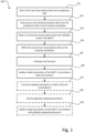
- Fig. 1 is a schematic flow chart representation of a method 100 performed by a computing system for performance evaluation (and updating) of a perception-development module of a vehicle in accordance with an embodiment of the present invention.
- the method may also be understood as a method 100 performed by an in-vehicle computing system for automated development of a perception-development module.
- the vehicle is further equipped with an Automated Driving System (ADS).
- ADS Automated Driving System
- the term "perception-development module” may be understood as "Module Under Test” (MUT), meaning that is a "new" (under development) software and/or hardware perception feature.
- the perception feature may for example be an object detection feature, an object classification feature, an object state estimation feature, a road reference estimation feature, a free-space estimation feature, a road friction estimation feature, an object trajectory estimation feature, a target/object tracking feature, and/or drivable area estimation feature.
- the perception-development module may in the present context be understood as software and/or hardware configured to generate a perception output based on input from one or more vehicle-mounted sensors, where the module is currently "under development", and not yet "in production” (e.g. not verified/validated).
- the method 100 comprises storing 101, during a time period, a first set of perception data obtained from a perception module (may also be referred to as a perception system) of the vehicle.
- the perception module is configured to generate the first set of perception data based on sensor data obtained from one or more vehicle-mounted sensors during the time period.
- a perception module/system is in the present context to be understood as a system responsible for acquiring raw sensor data from on-board sensors such as cameras, LIDARs RADARs, ultrasonic sensors, navigation system e.g. GPS, odometer and/or inertial measurement units, and converting this raw data into scene understanding.
- the term obtaining is herein to be interpreted broadly and encompasses receiving, retrieving, collecting, acquiring, and so forth.
- perception data may refer to “storing in one or more memories”, “storing on-board said vehicle”, “storing in one or more memories on-board said vehicle”, and/or “storing digitally and/or electronically” a set of perception data, and further to “collecting” and/or “obtaining” a set of perception data.
- set of perception data may refer to “range”, “amount”, “series”, “continuous and/or intermittent flow” and/or “collection” of perception data, whereas “perception data” may refer to “continuously and/or intermittently collected perception data”.
- perception data may refer to “surroundings assessment” data, “spatial perception” data, “processed sensory” data and/or “temporal dependencies” data, whereas perception “data” may refer to perception "information” and/or “estimates”.
- obtained” from a perception module may refer to “derived” from a perception model and/or “based on output data” from a perception module.
- perception module configured to "generate the set of perception data” may refer to perception module/system adapted and/or configured to "estimate the surroundings of said vehicle", “estimate at least a portion of surroundings of said vehicle”, “determine surroundings of said vehicle”, “interpret sensory information relevant for the autonomous manoeuvring of said vehicle”, and/or “estimate surroundings of said vehicle and make model predictions of future states of the surroundings of said vehicle”.
- perception model is in the present context to be understood as a software algorithm configured to receive input in the form of sensor data (raw or having some level of preprocessing) and to therefore generate an output comprising a representation of at least a portion of the surrounding environment of the vehicle.
- the perception model may for example be in the form of a neural network, and the model parameters may accordingly be in the form of network weights.
- time period may refer to “pre-determinable time period” and/or “predetermined time period”.
- time point may refer to "point in time”
- from a first time point to a second time point may refer to "from a first time point to a subsequent second time point”.
- a number of "perception models” may be used independently for different tasks such as lane segmentation, traffic sign identification, free-space estimation.
- these outputs should preferably be fused and provided as input for various "decision and control” functions, which supply the control signals for manoeuvring the vehicle autonomously.
- the method 100 comprises, forming 102, by post-processing the stored 101 first set of perception data, a baseline worldview.
- the baseline worldview comprises information indicative of a scenario in the surrounding environment of the vehicle during the time period.
- a scenario may be one or more momentary scenes at one or more points in time during the time period including the positions of detected objects, object classes/types, positions of lane markers, extensions of lane markers, free-space detections, and/or trajectories of detected objects. It should be noted that this list merely serves to exemplify the parameters included in a "scenario" and may include other parameters detectable by the vehicle's perception module as readily understood by the skilled person in the art.
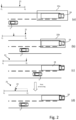
- Fig. 2 depicts a series (a) - (d) of schematic top-view illustrations of a vehicle 1 moving a road portion towards an external object 24. Each illustration is associated with a point in time within the time period 21 ranging from a first moment in time T1 to a second moment in time T2.
- the vehicle 1 (may also be referred to as ego-vehicle 1) is moving towards an external object, here in the form of a truck 24, that is traveling in the same direction on an adjacent lane on the road portion.
- an external object here in the form of a truck 24
- the vehicle's perception system/module may not be able to determine, with a sufficiently high level of accuracy, the position of the external object, and to classify it as a truck.
- the vehicle 1 is closer to the external object, and the uncertainties regarding the external object's 24 position and class/type are reduced, as indicated by the reduced size of the box 22b as compared to the first box 22a.
- the vehicle's 1 perception system/module is able to accurately determine the external object's 2 position and classify it as a truck 2. More specifically, the ego-vehicle 1 is now sufficiently close to the truck 2 to be able to classify it and estimate the truck's position on the road with a higher level of accuracy as compared to when the ego-vehicle 1 was located further away from the truck.
- the filtering may for example be based on the temporal development of the trajectories, positions, etc. in combination with predefined models (e.g. motion models) of the vehicle 1 and external objects 2.
- This established baseline worldview may subsequently used as a "ground truth” for training and/or validation of various perception output, and in particular for training and/or validation of the output obtained from the perception-development module.
- the baseline world-view constitutes a ground truth for the second set of perception data.
- the step of forming 102 the baseline worldview comprises determining, based on post-processing a portion of the first set of perception data ranging back from the second time point to an intermediate time point between the first time point T1 and second time point T2 the baseline worldview indicative of the surrounding environment of the vehicle.
- the baseline worldview accordingly being conditional on the portion of the first set of perception data.
- the post-processing of the portion of the first set of perception data comprises running the portion of the first set of perception data through a backwards filter.
- the backwards filter is configured to align a set of perceptive parameters of the first set of perception data at the intermediate time point based on a development of the state(s) of the set of perceptive parameters from the intermediate time point to the second time point T2.
- the post processing may for example comprise running the first set of perception data through a backwards filter configured to align e.g. the objects current and predicted future states with what happened in the future - i.e. from the intermediate time point to the second time point T2.
- the post-processing may include further processing steps than running it through a backwards filter.
- the post-processing may include fusion of data from various sensors, as well as applying backward and forward filtering on the fused information.
- Suitable filters for this purpose may for example be Particle filters or different types of Kalman filters (e.g. extended Kalman filters).
- the method 100 further comprises obtaining 103 a second set of perception data from the perception-development module.
- the perception-development module is configured to generate the second set of perception data based on a perception model and sensor data obtained from one or more vehicle-mounted sensors during the time period.
- the second set of perception data is indicative of at least one perceptive parameter of the surrounding environment of the vehicle during at least a moment in time within the time period.
- the second set of perception data may comprise a set of bounding boxes indicating a position and classification of a set of external objects (e.g. one or more vehicles) in the surrounding environment of the vehicle.
- the method 100 comprises matching 104 the second set of perception data to the formed baseline worldview in order to identify a match between the perceptive parameter of the second set of perception data and a corresponding perceptive parameter in the baseline worldview.
- the matching 104 may be construed as a comparison step between the second set of perception data and the formed baseline worldview so to identify a level of matching between one or more perceptive parameters (e.g. object positions) in the second set of perception data and the corresponding perceptive parameters in the baseline worldview.
- the matching 104 may include comparing the position of an identified vehicle in the second set of perception data with the position of that vehicle in the baseline worldview (e.g. as illustrated in Fig. 4 ).
- a purpose of the matching 104 is to match an object detected based on second set of perception data with one object from the baseline world view both corresponding to one unique object in the real world. After the corresponding objects from the two sets of perception data are matched together, the next step is to compare their associated perceptive parameter(s) (e.g. positions, speed, heading, etc.) and evaluate the performance of MUT.
- the matching 104 process will be further exemplified and elucidated with reference to Figs. 4 - 6 .
- the method 100 comprises evaluating 105 the obtained second set of perception data in reference to the baseline worldview in order to determine a cost function.
- This cost function is indicative of a performance of the perception-development module based on the identified match between the perceptive parameter of the second set of perception data and a corresponding perceptive parameter in the baseline worldview.
- the cost function (may also be referred to as a loss function) is determined based on the type of perceptive parameter.
- one cost function may be formed/defined if the perception model of the perception-development module is an object detection algorithm while another cost function may be formed/defined if it is a lane-tracing algorithm.
- the matching 104 step comprises identifying a match between the perceptive parameter of the second set of perception data and a corresponding perceptive parameter in the baseline worldview. Then, an estimation error of the matched perceptive parameter of the second set of perception data is determined. For example, if the perception model of the perception-development module is an object detection algorithm configured to generate bounding boxes, then a difference between the location and dimensions of these bounding boxes in the "second set of perception data" and the location and dimensions of the matched bounding boxes in the "baseline worldview" may be used to derive the "estimation error". In more detail, if the perceptive parameter is an object position estimation or an object occupancy estimation.
- the estimation error may then be in the form of a "lateral and longitudinal offset of closest point" between the bounding box representation of an object in the second set of perception data and the bounding box representation of the corresponding object in the baseline worldview.
- the term "closest point” may be understood the closest point of the detected object to the ego-vehicle. Accordingly, in some embodiments, the step of evaluating the obtained second set of perception data comprises determining/forming a cost function based on the determined estimation error.
- the matching 104 of the second set of perception data to the formed baseline worldview is only performed on the second set of perception data and the baseline worldview representative of a region of interest in the surrounding environment of the vehicle. For example, one may limit an "area" within which the matching 104 process is performed, such that one only compares the two datasets represented an area within a specific viewing frustum or within a certain distance from the vehicle. Thereby, objects that are further away from the ego-vehicle may be ignored as they are more likely to be associated with higher uncertainties and therefore more difficult to "match". This may consequently result in reduced processing power requirements for the matching process.
- the method 100 comprises updating 106 one or more parameters of the perception model of the perception-development module by means of an optimization algorithm (e.g. back propagation for neural networks) configured to minimize the calculated cost function.
- an optimization algorithm e.g. back propagation for neural networks
- the method 100 further comprises transmitting 107 the one or more updated parameters of the perception model of the perception-development module to a remote entity.
- the remote entity may for example be a central system or a cloud system capable of receiving and transmitting data to a fleet of ADS-equipped vehicles.
- the method 100 comprises receiving 108 a set of globally updated parameters of the perception model of the perception-development module from the remote entity. The set of globally updated parameters are accordingly based on information obtained from a plurality of vehicles comprising the perception-development module. Once, the set of globally updated parameters have been received 108, the method 100 may further comprise updating 109 the perception model of the perception-development module based on the received set of globally updated parameters.
- the transmitting 107 of the one or more updated model parameters is associated with a (predefined) trigger or criteria, where the updated model parameters are stored locally in the ego-vehicle until that trigger is detected or criteria is fulfilled. Once the trigger is detected, or once the criteria is fulfilled, the updated model parameters are transmitted 107 to the remote entity. Naturally, the time of transmission may further depend on external factors such as network availability and network quality.
- triggers or criteria include:
- the "base” perception model need not be the first perception model launched in the vehicles, but may for example be defined as the perception model obtained after the perception-development model has been updated 109 with the globally updated parameters.
- a new “base” perception model is defined, which in turn dictates the triggers/thresholds described above.
- the remote entity (may also be referred to as the "back-office"), consolidates the "learned" parameters of each vehicle in the entire fleet of vehicles, and pushes an update of the perception-development module to each vehicle in the fleet.
- the remote entity may utilize an entire fleet of production vehicles (instead of a few specialized "test-vehicles") to develop and verify various perception features associated with an ADS.
- model parameters e.g. network weights
- the "back-office” may in the present context be understood as a central entity responsible for the management and maintenance of the ADSs deployed in the vehicle fleet.
- Executable instructions for performing these functions are, optionally, included in a non-transitory computer-readable storage medium or other computer program product configured for execution by one or more processors.
- the present invention provides a time-efficient and cost-effective solution for developing consecutive releases of perception features for autonomous vehicles.
- the present inventors realized that once there is a "first" ADS released and deployed in a fleet of production vehicles, one can capitalize on the huge efforts (in terms of time and financial investments) associated with this first release, in order to develop consecutive releases of various perception features.
- the vehicles "out in traffic" i.e. production vehicles
- the solution proposed herein may be understood as a scheme of federated learning, effectively using learning at the edge (in each production vehicle) and then to potentially consolidate the learnt parameters/weights in a central/cloud unit.
- the present invention provides a solution that utilises the production vehicles to develop new perception features related to new sensor hardware as well as new algorithms for existing sensors by using federated learning.
- the production vehicle's own worldview is post-processed and used as a reference, towards which the output of the software- (SW) or hardware- (HW) -under-development is compared. Therefore, the method and system disclosed herein effectively supports cost-effective development of the next generation sensor platform (HW as well as SW) to reduce system cost for future products/systems. Further, one may similarly utilize the teachings herein to improve the efficiency of e.g. the vision and fusion algorithms to allow for execution on leaner computational hardware and thereby provide additional cost reductions of the hardware platform.
- the present inventors realized that once the ADS in the production vehicles is deployed, it can be assumed that it has been proven sufficiently safe (at least under certain conditions) including the perception and its performance. Therefore, a learning regime is herein proposed, where the worldview of the ADS is post-processed to construct a "baseline", towards which the output of the software-/hardware-under-development can be compared. Through this comparison a cost function can be calculated and an update of the SW parameters can be locally conducted according to this cost function. Furthermore, the locally updated SW across the fleet of production vehicles may be subsequently consolidated in the in a central system in order to push a "globally" updated version of the SW.
- the perception-development module (i.e. the module-under-test) may use the worldview as supplied by the "production platform" (i.e. the perception module of the ADS) as input.
- the perception-development module may be configured to generate the second set of perception data based on the perception model and the first set of perception data.
- the second set of perception data may comprise one or more prediction parameters (e.g. predictions of trajectories of external objects).
- the matching step as described in the foregoing may be omitted, as there is no need for any matching between the outputs (of the perception-development module and the platform perception module) as their "prediction models" rely on the same input.
- the second set of perception data may be received/obtained from a perception-development module configured to generate the second set of perception data based on a perception model and perception data obtained from the perception module (of the production platform) during the time period.
- the second set of perception data may be indicative of one or more prediction parameters of the surrounding environment of the vehicle during the time period.
- the evaluation 105 may accordingly be performed such that the one or more prediction parameters are evaluated in reference to the baseline worldview in order to determine a cost function indicative of a performance of the perception-development module based on one or more error parameters derived from the evaluation.
- Fig. 3 is a schematic block diagram representation of a system 10 for performance evaluation of a perception-development module of a vehicle, where the vehicle is equipped with an Automated Driving System (ADS).
- ADS Automated Driving System
- Fig. 3 depicts the flow of information through exposure to an event in the vehicle to the transmission and subsequent consolidation in the "back-office" 2.
- the system 10 comprises control circuitry configured to perform the functions of the methods disclosed herein, where the functions may be included in a non-transitory computer-readable storage medium or other computer program product configured for execution by the control circuitry.
- the control circuitry is represented as various "modules" in Fig. 3 , each of them linked to one or more specific functions.
- perception output for evaluation that is compared in the “evaluation engine” 35 could be any type of perception output e.g. objects, their states, free-space (the absence of objects), lanes, road position, driveable area, and combinations thereof.
- the system 10 comprises control circuitry configured to store, during a time period, a first set of perception data obtained from a perception module 32 of the vehicle.
- the perception module 32 is configured to generate the first set of perception data based on sensor data 31 obtained from one or more vehicle-mounted sensors during the time period.
- the sensor data 31 may for example output from one or more of a RADAR device, a LIDAR device, a camera, and ultrasonic sensor, and so forth.
- a "perception module” i.e.
- the perception system of the production platform is in the present context to be understood as a system responsible for acquiring raw sensor data from onboard sensors such as cameras, LIDARs and RADARs, ultrasonic sensors, and converting this raw data into scene understanding including state estimates and predictions thereof (i.e. to a "worldview").
- the first set of perception data may for example be stored or saved in a data buffer (not shown), where this first set of perception data may be understood as data indicative of the vehicle's surroundings. This may for example be detected objects or objects' states and/or vehicle localization, and/or statistical and physical model predictions of future states, derived continuously and/or intermittently from a first time point T1 to a second time point T2.
- the time period - and correspondingly the length of the optional data buffer - may be of any arbitrary size deemed feasible, e.g. in consideration of data capacity restraints and/or characteristics of the ADS, and may for instance range from under a second up to several minutes, or more preferred, from a few seconds up to less than a minute.
- the system 10 comprises a post-processing module 33 for forming a baseline worldview indicative of a scenario in the surrounding environment of the vehicle during the time period.
- the baseline worldview is formed based on the perception data generated by the perception module 32 of the production ADS. It should be noted that the term "forming, by post-processing the first set of perception data" does not necessarily mean that all of the stored data is post-processed, but should be construed as that at least a portion or at least a range of the stored perception data is post-processed.
- a second set of perception data is generated by a perception-development module (i.e. a Module Under Test, MUT) 34.
- This second set of data is obtained or received by an "evaluation engine” 35 of the system 10.
- the perception-development module 34 is configured to generate the second set of perception data based on a perception model and sensor data obtained from one or more vehicle-mounted sensors during the time period.
- the second set of perception data may be understood as a "perception output" from the MUT 34, and it is indicative of a perceptive parameter of the surrounding environment of the vehicle.
- the MUT 34 may comprise a lane tracing/tracking algorithm or a road geometry estimation algorithm.
- the output from the MUT may be a road reference feature estimation, such as e.g. a representation of the road or lane geometry in the surrounding environment of the vehicle during the time period.
- the input to the perception-development module 34 could be any combination of existing production sensors, their raw output, the raw detections or any more or less processed state in the chain. It could also be any combination of newly mounted sensors and their output (i.e. sensor output that is not used to generate the baseline worldview). For example, if one would want to test and evaluate an object detection algorithm that is based on a different type of input data from a new type of sensor as compared to the "production platform's" object detection algorithm.
- the evaluation engine 35 is configured to match the second set of perception data to the formed baseline worldview in order to identify a match between the perceptive parameter of the second set of perception data and a corresponding perceptive parameter in the baseline worldview.
- the evaluation engine 35 is configured to match the "perception-output for evaluation" with the corresponding features in the baseline worldview.
- the evaluation engine is configured to evaluate the obtained second set of perception data in reference to the baseline worldview in order to determine a cost function. This cost function is indicative of a performance of the perception-development module based on the identified match between the perceptive parameter of the second set of perception data and a corresponding perceptive parameter in the baseline worldview.
- the determined cost function is then received by the learning engine 36, which is configured to update one or more parameters of the perception model of the perception-development module 34 by means of an optimization algorithm configured to minimize the calculated cost function.
- the learning engine 36 is further configured to transmit the one or more locally updated parameters to a remote entity 2, where they are consolidated with updates received from other vehicles in the fleet, and then transmitted back to the learning engine 36 as a set of globally updated parameters. Then, the learning engine 36 may update the perception model of the perception-development module 34 based on the received set of globally updated parameters.
- the learning platform as proposed herein exposes the vision/perception baseline locally inside the platform such that the comparison/cost function used for evaluation or learning of the perception-development module 34 can be customised according to the present need. Further, the platform is proposed to include the redundant computational power necessary to achieve the comparison as well as the learning steps.
- the methods and systems as disclosed herein could be used to develop and launch new perception software or hardware versions in accordance with the following stages.
- a learning stage or phase and a consolidation phase where the new module is updated according to the flows depicted in Figs. 1 and 3 .
- the consolidated model parameters are pushed to the vehicle fleet for validation.
- the "learning part" of the process is not executed, i.e. in reference to Fig. 3 , the learning engine 36 is "short-circuited". Thus, only the evaluation part of the process is used.
- the new module passes the validation phase (i.e. the fail-rate is sufficiently low) in each vehicle of the fleet of vehicles, the final SW can be launched. However, if the validation fails, one can return to the beginning and start a new iteration of the process.
- Fig. 4 is a schematic perspective view of a matching process for matching a second set of perception data to a formed baseline worldview.
- the second set of perception data comprises an object detection estimation, and an example of how an estimation error of the detection is propagated to the evaluation and learning engines 34, 36 to update the model parameters of the perception-development module of the vehicle 1.
- the estimation error (indicated by the double-headed arrows) may for example a difference in the location between the bounding boxes around the detected objects 41a-c indicated in the second set of perception data and the bounding boxes around the corresponding objects 42a-c in the baseline worldview.
- Fig. 4 also serves to elucidate the matching process described in the foregoing.
- a match between the perceptive parameters of the second set of perception data and the corresponding perceptive parameters in the baseline worldview was identified for two of the vehicles 41a-b detected by the perception-development module, while no match could be identified for a third vehicle 41c.
- only the "matched" data, i.e. the identified matches are used for determining the cost function. This is in order to avoid propagating a mismatch (i.e. an erroneous interpretation of the surroundings) into the updating of the parameters of the perception model.
- the matching process serves to ensure that the correct comparison is being made between the second set of perception data and the first set of perception data.
- the matching process ensures that the red vehicle is matched to the corresponding red vehicle in the baseline worldview and the blue vehicle is matched to the corresponding blue vehicle in the baseline worldview. Otherwise, the perception model of the perception-development module may be trained with erroneous data (based on erroneous conclusions), which would decrease the performance of the perception-development module.
- the third vehicle 41c as detected by the perception-development module was not sufficiently close to any vehicle in the baseline worldview to identify any match, therefore this "data entry" may simply be discarded in the subsequent evaluation and learning/updating processes.
- Figs. 5 and 6 show the corresponding evaluation processes for perception models in the form of lane geometry estimations algorithms ( Fig. 5 ) and free-space detection algorithms ( Fig. 6 ).
- Fig. 5 is a schematic top-view illustration of a vehicle according to an embodiment of the present invention traveling on a road portion.
- the road portion has two lanes, and curves to the left in front of the vehicle 1.
- the "true" lane markings are indicated by reference numeral 53
- the baseline worldview's lane geometry estimation is indicated by reference numeral 52
- the perception-development module's lane geometry estimation is indicated by reference numeral 51.
- an estimation error 55 is derived in order to compute the cost function.
- the estimation error 55 is indicated as a difference between the locations/geometries of the lane geometry estimations 51, 52.
- the evaluation is performed in the image plane on a pixel level. Thereby, one can evaluate and train camera software directly on the pixel level.
- Fig. 6 is a schematic top-view illustration of a vehicle according to an embodiment of the present invention traveling on a road portion.
- the road portion has two lanes, and three external objects 63 in the form of two cars and a tractor located in front of the vehicle.
- the free-space estimation made by the production platform i.e. the free-space estimation of the baseline worldview is indicated by reference numeral 62, while the free-space estimation of the perception-development module is indicated by reference numeral 61.
- the estimation error 65 is, in the illustrated example, simply derived by a measurement or metric indicative of the nonoverlapping parts of the two free-space estimations 61, 62.
- this may be understood as the symmetric difference 65 between the free-space set defined by the free-space estimation of the perception development module and the free-space set defined by the baseline worldview.
- the estimation error 65 is used to compute the cost function, which is in turn used to update one or more parameters of the perception model of the perception-development module.
- Free-space areas may in the present context be understood as areas in the surrounding environment of the ego-vehicle absent of objects (e.g. other vehicles, pedestrians, barriers, animals, bicycles, static objects, etc.).
- the location of free-space areas may be understood as estimates of areas absent of external objects (static and dynamic objects).
- Fig. 7 depicts a schematic side view of a vehicle 1 comprising a system 10 for performance evaluation of a perception-development module of an ADS-equipped vehicle in accordance with an embodiment of the present invention.
- the vehicle 1 further comprises a perception module/system 6 (i.e. the perception system of the production platform), and a localization system 5.
- a perception system 6 is in the present context to be understood as a system responsible for acquiring raw sensor data from on-board sensors 6a, 6b, 6c such as cameras, LIDARs and RADARs, ultrasonic sensors, and converting this raw data into scene understanding.
- the localization system 5 is configured to monitor a geographical position and heading of the vehicle, and may in the form of a Global Navigation Satellite System (GNSS), such as a GPS. However, the localization system may alternatively be realized as a Real Time Kinematics (RTK) GPS in order to improve accuracy.
- GNSS Global Navigation Satellite System
- RTK Real Time Kinematics
- the perception module/system 6 may refer to any commonly known system and/or functionality, e.g. comprised in one or more electronic control modules and/or nodes of the vehicle 1, adapted and/or configured to interpret sensory information - relevant for driving of the vehicle 1 - to identify e.g. obstacles, vehicle lanes, relevant signage, appropriate navigation paths etc.
- the exemplified perception system 6 may thus be adapted to rely on and obtain inputs from multiple data sources, such as automotive imaging, image processing, computer vision, and/or in-car networking, etc., in combination with sensory information.
- Such exemplifying sensory information may for instance be derived from one or more optional surrounding detecting sensors 6a-c comprised in and/or provided on-board the vehicle 1.
- the surrounding detecting sensors 6a-c may be represented by any arbitrary sensors adapted to sense and/or perceive the vehicle's 1 surroundings and/or whereabouts, and may e.g. refer to one or a combination of one or more of radar, LIDAR, sonar, camera, navigation system e.g. GPS, odometer and/or inertial measurement units.
- the system 10 comprises one or more processors 11, a memory 12, a sensor interface 13 and a communication interface 14.
- the processor(s) 11 may also be referred to as a control circuit 11 or control circuitry 11.
- the control circuitry 11 is configured to execute instructions stored in the memory 12 to perform a method for performance evaluation of a perception-development module of a vehicle 1 according to any one of the embodiments disclosed herein.
- the memory 12 of the control device 10 can include one or more (non-transitory) computer-readable storage mediums, for storing computer-executable instructions, which, when executed by one or more computer processors 11, for example, can cause the computer processors 11 to perform the techniques described herein.
- the memory 12 optionally includes high-speed random access memory, such as DRAM, SRAM, DDR RAM, or other random access solid-state memory devices; and optionally includes non-volatile memory, such as one or more magnetic disk storage devices, optical disk storage devices, flash memory devices, or other non-volatile solid-state storage devices.
- high-speed random access memory such as DRAM, SRAM, DDR RAM, or other random access solid-state memory devices
- non-volatile memory such as one or more magnetic disk storage devices, optical disk storage devices, flash memory devices, or other non-volatile solid-state storage devices.
- the control circuitry 11 is configured to store, during a time period, a first set of perception data obtained from the perception module 6 of the vehicle.
- the perception module 6 is configured to generate the first set of perception data based on sensor data obtained from one or more vehicle-mounted sensors 6a-c during the time period.
- the control circuitry 11 is configured to form, by post-processing the first set of perception data, a baseline worldview indicative of a scenario in the surrounding environment of the vehicle during the time period.
- the control circuitry 11 is further configured to obtain a second set of perception data from the perception-development module (not shown in Fig. 7 ), where the perception-development module is configured to generate the second set of perception data based on a perception model and sensor data obtained from one or more vehicle-mounted sensors 6a-c during the time period.
- the second set of perception data is indicative of a perceptive parameter of the surrounding environment of the vehicle during the time period.
- the sensor data used for generating the first set of perception data need not be the same sensor data as used for generating the second set of perception data.
- the first set of perception data is generated based on a first set of sensor data
- the second set of perception data is generated based on a second set of sensor data.
- first set of sensor data is the same as the second set of sensor data, while in other embodiments the second set of sensor data is a subset of the first set of sensor data. Alternatively, the first set of sensor data is different from the second set of sensor data.
- control circuitry 11 is configured to match the second set of perception data to the formed baseline worldview in order to identify a match between the perceptive parameter of the second set of perception data and a corresponding perceptive parameter in the baseline worldview. Then, the control circuitry 11 is configured to evaluate the obtained second set of perception data in reference to the baseline worldview in order to determine a cost function indicative of a performance of the perception-development module based on the identified match between the perceptive parameter of the second set of perception data and a corresponding perceptive parameter in the baseline worldview. Still further, the control circuitry 11 is configured to update one or more parameters of the perception model of the perception-development module based on the output of an optimization algorithm configured to minimize the calculated cost function.
- the vehicle 1 may be connected to external network(s) 20 via for instance a wireless link (e.g. for transmitting and receiving model parameters).
- a wireless link e.g. for transmitting and receiving model parameters
- the same or some other wireless link may be used to communicate with other vehicles in the vicinity of the vehicle or with local infrastructure elements.
- Cellular communication technologies may be used for long range communication such as to external networks and if the cellular communication technology used have low latency it may also be used for communication between vehicles, vehicle to vehicle (V2V), and/or vehicle to infrastructure, V2X.
- Examples of cellular radio technologies are GSM, GPRS, EDGE, LTE, 5G, 5G NR, and so on, also including future cellular solutions.
- LAN Wireless Local Area
- ETSI is working on cellular standards for vehicle communication and for instance 5G is considered as a suitable solution due to the low latency and efficient handling of high bandwidths and communication channels.
- a non-transitory computer-readable storage medium storing one or more programs configured to be executed by one or more processors of a vehicle control system, the one or more programs comprising instructions for performing the method according to any one of the above-discussed embodiments.
- a computer-accessible medium may include any tangible or non-transitory storage media or memory media such as electronic, magnetic, or optical media-e.g., disk or CD/DVD-ROM coupled to computer system via bus.
- tangible and non-transitory are intended to describe a computer-readable storage medium (or “memory”) excluding propagating electromagnetic signals, but are not intended to otherwise limit the type of physical computer-readable storage device that is encompassed by the phrase computer-readable medium or memory.
- the terms “non-transitory computer-readable medium” or “tangible memory” are intended to encompass types of storage devices that do not necessarily store information permanently, including for example, random access memory (RAM).
- Program instructions and data stored on a tangible computer-accessible storage medium in non-transitory form may further be transmitted by transmission media or signals such as electrical, electromagnetic, or digital signals, which may be conveyed via a communication medium such as a network and/or a wireless link.
- transmission media or signals such as electrical, electromagnetic, or digital signals, which may be conveyed via a communication medium such as a network and/or a wireless link.
- the processor(s) 11 may be or include any number of hardware components for conducting data or signal processing or for executing computer code stored in memory 12.
- the device 10 has an associated memory 12, and the memory 12 may be one or more devices for storing data and/or computer code for completing or facilitating the various methods described in the present description.
- the memory may include volatile memory or non-volatile memory.
- the memory 12 may include database components, object code components, script components, or any other type of information structure for supporting the various activities of the present description. According to an exemplary embodiment, any distributed or local memory device may be utilized with the systems and methods of this description.
- the memory 12 is communicably connected to the processor 11 (e.g., via a circuit or any other wired, wireless, or network connection) and includes computer code for executing one or more processes described herein.
- the sensor interface 13 may also provide the possibility to acquire sensor data directly or via dedicated sensor control circuitry 6 in the vehicle.
- the communication/antenna interface 14 may further provide the possibility to send output to a remote location (e.g. remote operator or control centre) by means of the antenna 8.
- some sensors in the vehicle may communicate with the system 10 using a local network setup, such as CAN bus, I2C, Ethernet, optical fibres, and so on.
- the communication interface 14 may be arranged to communicate with other control functions of the vehicle and may thus be seen as control interface also; however, a separate control interface (not shown) may be provided.
- Local communication within the vehicle may also be of a wireless type with protocols such as WiFi, LoRa, Zigbee, Bluetooth, or similar mid/short range technologies.
Landscapes
- Engineering & Computer Science (AREA)
- Physics & Mathematics (AREA)
- Theoretical Computer Science (AREA)
- General Physics & Mathematics (AREA)
- Remote Sensing (AREA)
- Radar, Positioning & Navigation (AREA)
- Computer Vision & Pattern Recognition (AREA)
- Software Systems (AREA)
- Multimedia (AREA)
- Computer Networks & Wireless Communication (AREA)
- General Health & Medical Sciences (AREA)
- Artificial Intelligence (AREA)
- Evolutionary Computation (AREA)
- Health & Medical Sciences (AREA)
- Electromagnetism (AREA)
- General Engineering & Computer Science (AREA)
- Computing Systems (AREA)
- Databases & Information Systems (AREA)
- Medical Informatics (AREA)
- Business, Economics & Management (AREA)
- Data Mining & Analysis (AREA)
- Transportation (AREA)
- Mechanical Engineering (AREA)
- Automation & Control Theory (AREA)
- Human Computer Interaction (AREA)
- Economics (AREA)
- Bioinformatics & Cheminformatics (AREA)
- Human Resources & Organizations (AREA)
- Marketing (AREA)
- Primary Health Care (AREA)
- Strategic Management (AREA)
- Tourism & Hospitality (AREA)
- General Business, Economics & Management (AREA)
- Library & Information Science (AREA)
- Life Sciences & Earth Sciences (AREA)
- Evolutionary Biology (AREA)
- Bioinformatics & Computational Biology (AREA)
- Traffic Control Systems (AREA)
Claims (11)
- Verfahren (100), das durch ein Rechensystem zur Leistungsbewertung eines in der Entwicklung befindlichen Wahrnehmungsmoduls eines Fahrzeugs durchgeführt wird, wobei das Fahrzeug mit einem automatisierten Fahrsystem (Automated Driving System - ADS) ausgestattet ist, wobei das Verfahren Folgendes umfasst:Speichern (101) eines ersten Satzes von Wahrnehmungsdaten, der von einem Wahrnehmungssystem des Fahrzeugs erlangt wird, während eines Zeitraums, wobei das Wahrnehmungssystem dazu konfiguriert ist, den ersten Satz von Wahrnehmungsdaten auf Grundlage von Sensordaten zu generieren, die während des Zeitraums von einem oder mehreren am Fahrzeug montierten Sensoren erlangt werden;Bilden (102) einer Grundlinien-Wahrnehmungsausgabe, die Informationen umfasst, die ein Szenario in der Umgebung des Fahrzeugs während des Zeitraums angeben, durch Nachverarbeiten des ersten Satzes von Wahrnehmungsdaten;Erlangen (103) eines zweiten Satzes von Wahrnehmungsdaten von dem in der Entwicklung befindlichen Wahrnehmungsmodul, wobei das in der Entwicklung befindliche Wahrnehmungsmodul dazu konfiguriert ist, den zweiten Satz von Wahrnehmungsdaten auf Grundlage eines Wahrnehmungsmodells und von Sensordaten, die während des Zeitraums von einem oder mehreren am Fahrzeug montierten Sensoren erlangt werden, zu generieren;wobei der zweite Satz von Wahrnehmungsdaten einen Wahrnehmungsparameter der Umgebung des Fahrzeugs während des Zeitraums umfasst;wobei die Grundlinien-Wahrnehmungsausgabe Ground-Truth-Daten für den zweiten Satz von Wahrnehmungsdaten darstellt;Vergleichen (104) des zweiten Satzes von Wahrnehmungsdaten mit der gebildeten Grundlinien-Wahrnehmungsausgabe, um eine Übereinstimmung zwischen dem Wahrnehmungsparameter des zweiten Satzes von Wahrnehmungsdaten und einem entsprechenden Wahrnehmungsparameter in der Grundlinien-Wahrnehmungsausgabe zu identifizieren;Bewerten (105) des erlangten zweiten Satzes von Wahrnehmungsdaten in Bezug auf die Grundlinien-Wahrnehmungsausgabe, um auf Grundlage der identifizierten Übereinstimmung zwischen dem Wahrnehmungsparameter des zweiten Satzes von Wahrnehmungsdaten und dem entsprechenden Wahrnehmungsparameter in der Grundlinien-Wahrnehmungsausgabe eine Kostenfunktion zu bestimmen, die eine Leistung des in der Entwicklung befindlichen Wahrnehmungsmoduls angibt; undAktualisieren (106) eines oder mehrerer Parameter des Wahrnehmungsmodells des in der Entwicklung befindlichen Wahrnehmungsmoduls mittels eines Optimierungsalgorithmus, der dazu konfiguriert ist, die bestimmte Kostenfunktion zu minimieren.
- Verfahren (100) nach Anspruch 1, wobei der Wahrnehmungsparameter mindestens eines des Folgenden umfasst:eine Objektdetektionsschätzung;eine Objektklassifizierungsschätzung;eine Objektzustandsschätzung;eine Straßenreferenzmerkmalsschätzung;eine Freiraumschätzung;eine Straßenreibungsschätzung;eine Objektbewegungsbahnschätzung; undeine Schätzung eines befahrbaren Gebiets.
- Verfahren (100) nach einem der Ansprüche 1-2, ferner umfassend:Übertragen (107) des einen oder der mehreren aktualisierten Parameter des Wahrnehmungsmodells des in der Entwicklung befindlichen Wahrnehmungsmoduls an eine entfernte Einheit;Empfangen (108) eines Satzes global aktualisierter Parameter des Wahrnehmungsmodells des in der Entwicklung befindlichen Wahrnehmungsmoduls von der entfernten Einheit, wobei der Satz global aktualisierter Parameter auf Informationen basiert, die von einer Vielzahl von Fahrzeugen erlangt werden, die das in der Entwicklung befindliche Wahrnehmungsmodul umfasst;Aktualisieren (109) des Wahrnehmungsmodells des in der Entwicklung befindlichen Wahrnehmungsmoduls auf Grundlage des empfangenen Satzes global aktualisierter Parameter.
- Verfahren (100) nach einem der Ansprüche 1-3, wobei der Zeitraum von einem ersten Zeitpunkt zu einem zweiten Zeitpunkt reicht und wobei der Schritt des Bildens (102) der Grundlinien-Wahrnehmungsausgabe Folgendes umfasst:
Bestimmen der Grundlinien-Wahrnehmungsausgabe, die Informationen umfasst, welche die Umgebung des Fahrzeugs an dem zwischenliegenden Zeitpunkt in Abhängigkeit von dem Teil des ersten Satzes von Wahrnehmungsdaten angeben, auf Grundlage eines Nachverarbeitens eines Teils des ersten Satzes von Wahrnehmungsdaten, der von dem zweiten Zeitpunkt zu einem zwischenliegenden Zeitpunkt zwischen dem ersten und dem zweiten Zeitpunkt zurückreicht. - Verfahren (100) nach Anspruch 4, wobei das Nachverarbeiten des Teils des ersten Satzes von Wahrnehmungsdaten Folgendes umfasst:
Laufenlassen des Teils des ersten Satzes von Wahrnehmungsdaten durch ein Rückwärtsfilter, das dazu konfiguriert ist, einen Satz von Wahrnehmungsparametern des ersten Satzes von Wahrnehmungsdaten an dem zwischenliegenden Zeitpunkt auf Grundlage einer zeitlichen Entwicklung des Satzes von Wahrnehmungsparametern von dem zwischenliegenden Zeitpunkt zu dem zweiten Zeitpunkt anzupassen. - Verfahren (100) nach einem der Ansprüche 1-5, wobei das Abgleichen (104) des zweiten Satzes von Wahrnehmungsdaten mit der gebildeten Grundlinien-Wahrnehmungsausgabe Folgendes umfasst:Identifizieren einer Übereinstimmung zwischen dem Wahrnehmungsparameter (41a-b, 51, 61) des zweiten Satzes von Wahrnehmungsdaten und einem entsprechenden Wahrnehmungsparameter (42a-b, 52, 62) in der Grundlinien-Wahrnehmungsausgabe;Bestimmen eines Schätzfehlers (55, 65) des abgeglichenen Wahrnehmungsparameters des zweiten Satzes von Wahrnehmungsdaten;wobei der Schritt des Bewertens des erlangten zweites Satzes von Wahrnehmungsdaten Bestimmen der Kostenfunktion auf Grundlage des bestimmten Schätzfehlers umfasst.
- Verfahren (100) nach einem der Ansprüche 1-6, wobei die Kostenfunktion auf Grundlage der Art des Wahrnehmungsparameters bestimmt wird.
- Verfahren (100) nach einem der Ansprüche 1-7, wobei das Abgleichen des zweiten Satzes von Wahrnehmungsdaten mit der gebildeten Grundlinien-Wahrnehmungsausgabe nur an dem zweiten Satz von Wahrnehmungsdaten und der Grundlinien-Wahrnehmungsausgabe durchgeführt wird, die eine Region von Interesse in der Umgebung des Fahrzeugs wiedergeben.
- Computerlesbares Speichermedium, das ein oder mehrere Programme speichert, die dazu konfiguriert sind, durch einen oder mehrere Prozessoren eines fahrzeuginternen Verarbeitungssystems ausgeführt zu werden, wobei das eine oder die mehreren Programme Anweisungen zum Durchführen des Verfahrens (100) nach einem der Ansprüche 1-8 umfassen.
- System (10) zur Leistungsbewertung eines in der Entwicklung befindlichen Wahrnehmungsmoduls (34) eines Fahrzeugs (1), wobei das Fahrzeug mit einem automatisierten Fahrsystem (ADS) ausgestattet ist, wobei das System eine Steuerschaltung umfasst, die zu Folgendem konfiguriert ist:Speichern eines ersten Satzes von Wahrnehmungsdaten, der von einem Wahrnehmungssystem (6, 32) des Fahrzeugs erlangt wird, während eines Zeitraums, wobei das Wahrnehmungssystem dazu konfiguriert ist, den ersten Satz von Wahrnehmungsdaten auf Grundlage von Sensordaten (31) zu generieren, die während des Zeitraums von einem oder mehreren am Fahrzeug montierten Sensoren (6a, 6b, 6c) erlangt werden;Bilden einer Grundlinien-Wahrnehmungsausgabe, die Informationen umfasst, die ein Szenario in der Umgebung des Fahrzeugs während des Zeitraums angeben, durch Nachverarbeiten des ersten Satzes von Wahrnehmungsdaten;Erlangen eines zweiten Satzes von Wahrnehmungsdaten von dem in der Entwicklung befindlichen Wahrnehmungsmodul (34), wobei das in der Entwicklung befindliche Wahrnehmungsmodul dazu konfiguriert ist, den zweiten Satz von Wahrnehmungsdaten auf Grundlage eines Wahrnehmungsmodells und von Sensordaten (31), die von einem oder mehreren am Fahrzeug montierten Sensoren (6a, 6b, 6c) während des Zeitraums erlangt werden, zu generieren;wobei der zweite Satz von Wahrnehmungsdaten einen Wahrnehmungsparameter der Umgebung des Fahrzeugs (1) während des Zeitraums umfasst;Vergleichen des zweiten Satzes von Wahrnehmungsdaten mit der gebildeten Grundlinien-Wahrnehmungsausgabe, um eine Übereinstimmung zwischen dem Wahrnehmungsparameter des zweiten Satzes von Wahrnehmungsdaten und einem entsprechenden Wahrnehmungsparameter in der Grundlinien-Wahrnehmungsausgabe zu identifizieren;Bewerten des erlangten zweiten Satzes von Wahrnehmungsdaten in Bezug auf die Grundlinien-Wahrnehmungsausgabe, um auf Grundlage der identifizierten Übereinstimmung zwischen dem Wahrnehmungsparameter des zweiten Satzes von Wahrnehmungsdaten und einem entsprechenden Wahrnehmungsparameter in der Grundlinien-Wahrnehmungsausgabe eine Kostenfunktion zu bestimmen, die eine Leistung des in der Entwicklung befindlichen Wahrnehmungsmoduls angibt; undAktualisieren eines oder mehrerer Parameter des Wahrnehmungsmodells des in der Entwicklung befindlichen Wahrnehmungsmoduls (34) mittels eines Optimierungsalgorithmus, der dazu konfiguriert ist, die bestimmte Kostenfunktion zu minimieren.
- Fahrzeug (1), umfassend:einen Satz am Fahrzeug montierter Sensoren (6a, 6b, 6c), der dazu konfiguriert ist, eine Umgebung des Fahrzeugs zu überwachen;ein automatisiertes Fahrsystem (ADS), das ein Wahrnehmungssystem 6, 32) aufweist, das dazu konfiguriert ist, einen ersten Satz von Wahrnehmungsdaten auf Grundlage von Sensordaten zu generieren, die von einem oder mehreren des Satzes am Fahrzeug montierter Sensoren erlangt werden;ein in der Entwicklung befindliches Wahrnehmungsmodul (34), das dazu konfiguriert ist, den zweiten Satz von Wahrnehmungsdaten auf Grundlage eines Wahrnehmungsmodells und von Sensordaten, die von einem oder mehreren des Satzes am Fahrzeug montierter Sensoren erlangt werden, zu generieren;ein System nach Anspruch 10.
Priority Applications (3)
| Application Number | Priority Date | Filing Date | Title |
|---|---|---|---|
| EP21158017.0A EP4047515B1 (de) | 2021-02-19 | 2021-02-19 | Plattform zur entwicklung eines wahrnehmungssystems für automatisierte antriebssysteme |
| US17/672,791 US12240487B2 (en) | 2021-02-19 | 2022-02-16 | Platform for perception system development for automated driving systems |
| CN202210150331.8A CN114968187A (zh) | 2021-02-19 | 2022-02-18 | 用于自动驾驶系统的感知系统开发的平台 |
Applications Claiming Priority (1)
| Application Number | Priority Date | Filing Date | Title |
|---|---|---|---|
| EP21158017.0A EP4047515B1 (de) | 2021-02-19 | 2021-02-19 | Plattform zur entwicklung eines wahrnehmungssystems für automatisierte antriebssysteme |
Publications (2)
| Publication Number | Publication Date |
|---|---|
| EP4047515A1 EP4047515A1 (de) | 2022-08-24 |
| EP4047515B1 true EP4047515B1 (de) | 2023-10-11 |
Family
ID=74732582
Family Applications (1)
| Application Number | Title | Priority Date | Filing Date |
|---|---|---|---|
| EP21158017.0A Active EP4047515B1 (de) | 2021-02-19 | 2021-02-19 | Plattform zur entwicklung eines wahrnehmungssystems für automatisierte antriebssysteme |
Country Status (3)
| Country | Link |
|---|---|
| US (1) | US12240487B2 (de) |
| EP (1) | EP4047515B1 (de) |
| CN (1) | CN114968187A (de) |
Families Citing this family (2)
| Publication number | Priority date | Publication date | Assignee | Title |
|---|---|---|---|---|
| US20230303092A1 (en) * | 2022-03-28 | 2023-09-28 | Gm Cruise Holdings Llc | Perception error identification |
| CN116049292B (zh) * | 2023-03-07 | 2023-05-30 | 千巡科技(深圳)有限公司 | 一种基于转换联动的环境感知方法、系统、装置以及介质 |
Family Cites Families (8)
| Publication number | Priority date | Publication date | Assignee | Title |
|---|---|---|---|---|
| US10762358B2 (en) * | 2016-07-20 | 2020-09-01 | Ford Global Technologies, Llc | Rear camera lane detection |
| US10884409B2 (en) * | 2017-05-01 | 2021-01-05 | Mentor Graphics (Deutschland) Gmbh | Training of machine learning sensor data classification system |
| US10816354B2 (en) * | 2017-08-22 | 2020-10-27 | Tusimple, Inc. | Verification module system and method for motion-based lane detection with multiple sensors |
| WO2019232335A1 (en) * | 2018-06-01 | 2019-12-05 | Volkswagen Group Of America, Inc. | Methodologies, systems, and components for incremental and continual learning for scalable improvement of autonomous systems |
| ES3032881T3 (en) * | 2018-09-14 | 2025-07-28 | Tesla Inc | System and method for obtaining training data |
| WO2020079698A1 (en) * | 2018-10-19 | 2020-04-23 | A.D Knight Ltd. | Adas systems functionality testing |
| US20200210778A1 (en) * | 2018-12-26 | 2020-07-02 | Yandex.Taxi LLC | Methods and systems for generating training data for neural network |
| US11657591B2 (en) * | 2021-01-15 | 2023-05-23 | Argo AI, LLC | Autonomous vehicle system for intelligent on-board selection of data for building a remote machine learning model |
-
2021
- 2021-02-19 EP EP21158017.0A patent/EP4047515B1/de active Active
-
2022
- 2022-02-16 US US17/672,791 patent/US12240487B2/en active Active
- 2022-02-18 CN CN202210150331.8A patent/CN114968187A/zh active Pending
Also Published As
| Publication number | Publication date |
|---|---|
| EP4047515A1 (de) | 2022-08-24 |
| US20220266856A1 (en) | 2022-08-25 |
| CN114968187A (zh) | 2022-08-30 |
| US12240487B2 (en) | 2025-03-04 |
Similar Documents
| Publication | Publication Date | Title |
|---|---|---|
| US12195021B2 (en) | Platform for perception system development for automated driving system | |
| US12377837B2 (en) | Path planning in autonomous driving environments | |
| US12077171B2 (en) | Vehicle control device, automated driving vehicle development system, vehicle control method, and storage medium for verifying control logic | |
| US12222726B2 (en) | Platform for path planning system development for automated driving system | |
| EP3896639B1 (de) | Verfahren und systeme zur verwaltung eines automatisierten fahrsystems eines fahrzeugs | |
| US11897501B2 (en) | ADS perception development | |
| EP4394626A1 (de) | Klassifizierung von objekten auf einer strasse | |
| US12240487B2 (en) | Platform for perception system development for automated driving systems | |
| CN115629375A (zh) | 使用交通工具对交通工具技术提高雷达数据预测的准确度 | |
| US11983918B2 (en) | Platform for perception system development for automated driving system | |
| US12227195B2 (en) | Hypothesis inference for vehicles | |
| US20250148372A1 (en) | Automated data annotation for machine learning applications | |
| WO2022258203A1 (en) | Platform for perception function development for automated driving system | |
| US20230090338A1 (en) | Method and system for evaluation and development of automated driving system features or functions | |
| US20230091986A1 (en) | Method and system for evaluation and development of automated driving system features | |
| EP4517380A1 (de) | Überwachungsplattform für ein sensorfusionssystem | |
| US20250209872A1 (en) | Methods and systems for setting dynamic triggers for event recordings for a vehicle | |
| EP4394664A1 (de) | Automatisierte datenerzeugung durch neuronale netzwerkensembles | |
| EP4576023A1 (de) | Verfahren zur erzeugung eines annotierten trainingsdatensatzes zum trainieren eines wahrnehmungsalgorithmus eines automatisierten fahrsystems |
Legal Events
| Date | Code | Title | Description |
|---|---|---|---|
| PUAI | Public reference made under article 153(3) epc to a published international application that has entered the european phase |
Free format text: ORIGINAL CODE: 0009012 |
|
| STAA | Information on the status of an ep patent application or granted ep patent |
Free format text: STATUS: THE APPLICATION HAS BEEN PUBLISHED |
|
| AK | Designated contracting states |
Kind code of ref document: A1 Designated state(s): AL AT BE BG CH CY CZ DE DK EE ES FI FR GB GR HR HU IE IS IT LI LT LU LV MC MK MT NL NO PL PT RO RS SE SI SK SM TR |
|
| STAA | Information on the status of an ep patent application or granted ep patent |
Free format text: STATUS: REQUEST FOR EXAMINATION WAS MADE |
|
| 17P | Request for examination filed |
Effective date: 20230224 |
|
| RBV | Designated contracting states (corrected) |
Designated state(s): AL AT BE BG CH CY CZ DE DK EE ES FI FR GB GR HR HU IE IS IT LI LT LU LV MC MK MT NL NO PL PT RO RS SE SI SK SM TR |
|
| REG | Reference to a national code |
Ref country code: DE Ref legal event code: R079 Free format text: PREVIOUS MAIN CLASS: G06K0009000000 Ipc: G06F0018210000 Ref country code: DE Ref legal event code: R079 Ref document number: 602021005708 Country of ref document: DE Free format text: PREVIOUS MAIN CLASS: G06K0009000000 Ipc: G06F0018210000 |
|
| GRAP | Despatch of communication of intention to grant a patent |
Free format text: ORIGINAL CODE: EPIDOSNIGR1 |
|
| STAA | Information on the status of an ep patent application or granted ep patent |
Free format text: STATUS: GRANT OF PATENT IS INTENDED |
|
| RIC1 | Information provided on ipc code assigned before grant |
Ipc: G06V 10/80 20220101ALI20230405BHEP Ipc: G06V 20/56 20220101ALI20230405BHEP Ipc: G06V 20/58 20220101ALI20230405BHEP Ipc: G06F 18/21 20230101AFI20230405BHEP |
|
| INTG | Intention to grant announced |
Effective date: 20230509 |
|
| GRAS | Grant fee paid |
Free format text: ORIGINAL CODE: EPIDOSNIGR3 |
|
| GRAA | (expected) grant |
Free format text: ORIGINAL CODE: 0009210 |
|
| STAA | Information on the status of an ep patent application or granted ep patent |
Free format text: STATUS: THE PATENT HAS BEEN GRANTED |
|
| AK | Designated contracting states |
Kind code of ref document: B1 Designated state(s): AL AT BE BG CH CY CZ DE DK EE ES FI FR GB GR HR HU IE IS IT LI LT LU LV MC MK MT NL NO PL PT RO RS SE SI SK SM TR |
|
| REG | Reference to a national code |
Ref country code: GB Ref legal event code: FG4D |
|
| REG | Reference to a national code |
Ref country code: CH Ref legal event code: EP |
|
| REG | Reference to a national code |
Ref country code: DE Ref legal event code: R096 Ref document number: 602021005708 Country of ref document: DE |
|
| P01 | Opt-out of the competence of the unified patent court (upc) registered |
Effective date: 20231004 |
|
| REG | Reference to a national code |
Ref country code: IE Ref legal event code: FG4D |
|
| REG | Reference to a national code |
Ref country code: SE Ref legal event code: TRGR |
|
| REG | Reference to a national code |
Ref country code: LT Ref legal event code: MG9D |
|
| REG | Reference to a national code |
Ref country code: NL Ref legal event code: MP Effective date: 20231011 |
|
| REG | Reference to a national code |
Ref country code: AT Ref legal event code: MK05 Ref document number: 1620918 Country of ref document: AT Kind code of ref document: T Effective date: 20231011 |
|
| PG25 | Lapsed in a contracting state [announced via postgrant information from national office to epo] |
Ref country code: NL Free format text: LAPSE BECAUSE OF FAILURE TO SUBMIT A TRANSLATION OF THE DESCRIPTION OR TO PAY THE FEE WITHIN THE PRESCRIBED TIME-LIMIT Effective date: 20231011 |
|
| PG25 | Lapsed in a contracting state [announced via postgrant information from national office to epo] |
Ref country code: GR Free format text: LAPSE BECAUSE OF FAILURE TO SUBMIT A TRANSLATION OF THE DESCRIPTION OR TO PAY THE FEE WITHIN THE PRESCRIBED TIME-LIMIT Effective date: 20240112 |
|
| PG25 | Lapsed in a contracting state [announced via postgrant information from national office to epo] |
Ref country code: IS Free format text: LAPSE BECAUSE OF FAILURE TO SUBMIT A TRANSLATION OF THE DESCRIPTION OR TO PAY THE FEE WITHIN THE PRESCRIBED TIME-LIMIT Effective date: 20240211 |
|
| PG25 | Lapsed in a contracting state [announced via postgrant information from national office to epo] |
Ref country code: LT Free format text: LAPSE BECAUSE OF FAILURE TO SUBMIT A TRANSLATION OF THE DESCRIPTION OR TO PAY THE FEE WITHIN THE PRESCRIBED TIME-LIMIT Effective date: 20231011 |
|
| PG25 | Lapsed in a contracting state [announced via postgrant information from national office to epo] |
Ref country code: AT Free format text: LAPSE BECAUSE OF FAILURE TO SUBMIT A TRANSLATION OF THE DESCRIPTION OR TO PAY THE FEE WITHIN THE PRESCRIBED TIME-LIMIT Effective date: 20231011 |
|
| PG25 | Lapsed in a contracting state [announced via postgrant information from national office to epo] |
Ref country code: ES Free format text: LAPSE BECAUSE OF FAILURE TO SUBMIT A TRANSLATION OF THE DESCRIPTION OR TO PAY THE FEE WITHIN THE PRESCRIBED TIME-LIMIT Effective date: 20231011 |
|
| PG25 | Lapsed in a contracting state [announced via postgrant information from national office to epo] |
Ref country code: LT Free format text: LAPSE BECAUSE OF FAILURE TO SUBMIT A TRANSLATION OF THE DESCRIPTION OR TO PAY THE FEE WITHIN THE PRESCRIBED TIME-LIMIT Effective date: 20231011 Ref country code: IS Free format text: LAPSE BECAUSE OF FAILURE TO SUBMIT A TRANSLATION OF THE DESCRIPTION OR TO PAY THE FEE WITHIN THE PRESCRIBED TIME-LIMIT Effective date: 20240211 Ref country code: GR Free format text: LAPSE BECAUSE OF FAILURE TO SUBMIT A TRANSLATION OF THE DESCRIPTION OR TO PAY THE FEE WITHIN THE PRESCRIBED TIME-LIMIT Effective date: 20240112 Ref country code: ES Free format text: LAPSE BECAUSE OF FAILURE TO SUBMIT A TRANSLATION OF THE DESCRIPTION OR TO PAY THE FEE WITHIN THE PRESCRIBED TIME-LIMIT Effective date: 20231011 Ref country code: BG Free format text: LAPSE BECAUSE OF FAILURE TO SUBMIT A TRANSLATION OF THE DESCRIPTION OR TO PAY THE FEE WITHIN THE PRESCRIBED TIME-LIMIT Effective date: 20240111 Ref country code: AT Free format text: LAPSE BECAUSE OF FAILURE TO SUBMIT A TRANSLATION OF THE DESCRIPTION OR TO PAY THE FEE WITHIN THE PRESCRIBED TIME-LIMIT Effective date: 20231011 Ref country code: PT Free format text: LAPSE BECAUSE OF FAILURE TO SUBMIT A TRANSLATION OF THE DESCRIPTION OR TO PAY THE FEE WITHIN THE PRESCRIBED TIME-LIMIT Effective date: 20240212 |
|
| PG25 | Lapsed in a contracting state [announced via postgrant information from national office to epo] |
Ref country code: RS Free format text: LAPSE BECAUSE OF FAILURE TO SUBMIT A TRANSLATION OF THE DESCRIPTION OR TO PAY THE FEE WITHIN THE PRESCRIBED TIME-LIMIT Effective date: 20231011 Ref country code: PL Free format text: LAPSE BECAUSE OF FAILURE TO SUBMIT A TRANSLATION OF THE DESCRIPTION OR TO PAY THE FEE WITHIN THE PRESCRIBED TIME-LIMIT Effective date: 20231011 Ref country code: NO Free format text: LAPSE BECAUSE OF FAILURE TO SUBMIT A TRANSLATION OF THE DESCRIPTION OR TO PAY THE FEE WITHIN THE PRESCRIBED TIME-LIMIT Effective date: 20240111 Ref country code: LV Free format text: LAPSE BECAUSE OF FAILURE TO SUBMIT A TRANSLATION OF THE DESCRIPTION OR TO PAY THE FEE WITHIN THE PRESCRIBED TIME-LIMIT Effective date: 20231011 Ref country code: HR Free format text: LAPSE BECAUSE OF FAILURE TO SUBMIT A TRANSLATION OF THE DESCRIPTION OR TO PAY THE FEE WITHIN THE PRESCRIBED TIME-LIMIT Effective date: 20231011 |
|
| PG25 | Lapsed in a contracting state [announced via postgrant information from national office to epo] |
Ref country code: DK Free format text: LAPSE BECAUSE OF FAILURE TO SUBMIT A TRANSLATION OF THE DESCRIPTION OR TO PAY THE FEE WITHIN THE PRESCRIBED TIME-LIMIT Effective date: 20231011 |
|
| REG | Reference to a national code |
Ref country code: DE Ref legal event code: R097 Ref document number: 602021005708 Country of ref document: DE |
|
| PG25 | Lapsed in a contracting state [announced via postgrant information from national office to epo] |
Ref country code: CZ Free format text: LAPSE BECAUSE OF FAILURE TO SUBMIT A TRANSLATION OF THE DESCRIPTION OR TO PAY THE FEE WITHIN THE PRESCRIBED TIME-LIMIT Effective date: 20231011 |
|
| PG25 | Lapsed in a contracting state [announced via postgrant information from national office to epo] |
Ref country code: SK Free format text: LAPSE BECAUSE OF FAILURE TO SUBMIT A TRANSLATION OF THE DESCRIPTION OR TO PAY THE FEE WITHIN THE PRESCRIBED TIME-LIMIT Effective date: 20231011 |
|
| PG25 | Lapsed in a contracting state [announced via postgrant information from national office to epo] |
Ref country code: SM Free format text: LAPSE BECAUSE OF FAILURE TO SUBMIT A TRANSLATION OF THE DESCRIPTION OR TO PAY THE FEE WITHIN THE PRESCRIBED TIME-LIMIT Effective date: 20231011 Ref country code: SK Free format text: LAPSE BECAUSE OF FAILURE TO SUBMIT A TRANSLATION OF THE DESCRIPTION OR TO PAY THE FEE WITHIN THE PRESCRIBED TIME-LIMIT Effective date: 20231011 Ref country code: RO Free format text: LAPSE BECAUSE OF FAILURE TO SUBMIT A TRANSLATION OF THE DESCRIPTION OR TO PAY THE FEE WITHIN THE PRESCRIBED TIME-LIMIT Effective date: 20231011 Ref country code: IT Free format text: LAPSE BECAUSE OF FAILURE TO SUBMIT A TRANSLATION OF THE DESCRIPTION OR TO PAY THE FEE WITHIN THE PRESCRIBED TIME-LIMIT Effective date: 20231011 Ref country code: EE Free format text: LAPSE BECAUSE OF FAILURE TO SUBMIT A TRANSLATION OF THE DESCRIPTION OR TO PAY THE FEE WITHIN THE PRESCRIBED TIME-LIMIT Effective date: 20231011 Ref country code: DK Free format text: LAPSE BECAUSE OF FAILURE TO SUBMIT A TRANSLATION OF THE DESCRIPTION OR TO PAY THE FEE WITHIN THE PRESCRIBED TIME-LIMIT Effective date: 20231011 Ref country code: CZ Free format text: LAPSE BECAUSE OF FAILURE TO SUBMIT A TRANSLATION OF THE DESCRIPTION OR TO PAY THE FEE WITHIN THE PRESCRIBED TIME-LIMIT Effective date: 20231011 |
|
| PLBE | No opposition filed within time limit |
Free format text: ORIGINAL CODE: 0009261 |
|
| STAA | Information on the status of an ep patent application or granted ep patent |
Free format text: STATUS: NO OPPOSITION FILED WITHIN TIME LIMIT |
|
| 26N | No opposition filed |
Effective date: 20240712 |
|
| PG25 | Lapsed in a contracting state [announced via postgrant information from national office to epo] |
Ref country code: MC Free format text: LAPSE BECAUSE OF FAILURE TO SUBMIT A TRANSLATION OF THE DESCRIPTION OR TO PAY THE FEE WITHIN THE PRESCRIBED TIME-LIMIT Effective date: 20231011 |
|
| REG | Reference to a national code |
Ref country code: CH Ref legal event code: PL |
|
| PG25 | Lapsed in a contracting state [announced via postgrant information from national office to epo] |
Ref country code: LU Free format text: LAPSE BECAUSE OF NON-PAYMENT OF DUE FEES Effective date: 20240219 |
|
| PG25 | Lapsed in a contracting state [announced via postgrant information from national office to epo] |
Ref country code: CH Free format text: LAPSE BECAUSE OF NON-PAYMENT OF DUE FEES Effective date: 20240229 |
|
| PG25 | Lapsed in a contracting state [announced via postgrant information from national office to epo] |
Ref country code: SI Free format text: LAPSE BECAUSE OF FAILURE TO SUBMIT A TRANSLATION OF THE DESCRIPTION OR TO PAY THE FEE WITHIN THE PRESCRIBED TIME-LIMIT Effective date: 20231011 |
|
| PG25 | Lapsed in a contracting state [announced via postgrant information from national office to epo] |
Ref country code: SI Free format text: LAPSE BECAUSE OF FAILURE TO SUBMIT A TRANSLATION OF THE DESCRIPTION OR TO PAY THE FEE WITHIN THE PRESCRIBED TIME-LIMIT Effective date: 20231011 Ref country code: LU Free format text: LAPSE BECAUSE OF NON-PAYMENT OF DUE FEES Effective date: 20240219 Ref country code: CH Free format text: LAPSE BECAUSE OF NON-PAYMENT OF DUE FEES Effective date: 20240229 |
|
| REG | Reference to a national code |
Ref country code: BE Ref legal event code: MM Effective date: 20240229 |
|
| PG25 | Lapsed in a contracting state [announced via postgrant information from national office to epo] |
Ref country code: BE Free format text: LAPSE BECAUSE OF NON-PAYMENT OF DUE FEES Effective date: 20240229 |
|
| PG25 | Lapsed in a contracting state [announced via postgrant information from national office to epo] |
Ref country code: FR Free format text: LAPSE BECAUSE OF NON-PAYMENT OF DUE FEES Effective date: 20240229 |
|
| PG25 | Lapsed in a contracting state [announced via postgrant information from national office to epo] |
Ref country code: IE Free format text: LAPSE BECAUSE OF NON-PAYMENT OF DUE FEES Effective date: 20240219 |
|
| PG25 | Lapsed in a contracting state [announced via postgrant information from national office to epo] |
Ref country code: IE Free format text: LAPSE BECAUSE OF NON-PAYMENT OF DUE FEES Effective date: 20240219 Ref country code: FR Free format text: LAPSE BECAUSE OF NON-PAYMENT OF DUE FEES Effective date: 20240229 Ref country code: BE Free format text: LAPSE BECAUSE OF NON-PAYMENT OF DUE FEES Effective date: 20240229 |
|
| PG25 | Lapsed in a contracting state [announced via postgrant information from national office to epo] |
Ref country code: CY Free format text: LAPSE BECAUSE OF FAILURE TO SUBMIT A TRANSLATION OF THE DESCRIPTION OR TO PAY THE FEE WITHIN THE PRESCRIBED TIME-LIMIT; INVALID AB INITIO Effective date: 20210219 |
|
| PG25 | Lapsed in a contracting state [announced via postgrant information from national office to epo] |
Ref country code: HU Free format text: LAPSE BECAUSE OF FAILURE TO SUBMIT A TRANSLATION OF THE DESCRIPTION OR TO PAY THE FEE WITHIN THE PRESCRIBED TIME-LIMIT; INVALID AB INITIO Effective date: 20210219 |
|
| PG25 | Lapsed in a contracting state [announced via postgrant information from national office to epo] |
Ref country code: FI Free format text: LAPSE BECAUSE OF FAILURE TO SUBMIT A TRANSLATION OF THE DESCRIPTION OR TO PAY THE FEE WITHIN THE PRESCRIBED TIME-LIMIT Effective date: 20231011 |
|
| PG25 | Lapsed in a contracting state [announced via postgrant information from national office to epo] |
Ref country code: TR Free format text: LAPSE BECAUSE OF FAILURE TO SUBMIT A TRANSLATION OF THE DESCRIPTION OR TO PAY THE FEE WITHIN THE PRESCRIBED TIME-LIMIT Effective date: 20231011 |
|
| PGFP | Annual fee paid to national office [announced via postgrant information from national office to epo] |
Ref country code: GB Payment date: 20251211 Year of fee payment: 6 |
|
| PGFP | Annual fee paid to national office [announced via postgrant information from national office to epo] |
Ref country code: SE Payment date: 20251208 Year of fee payment: 6 |
|
| PGFP | Annual fee paid to national office [announced via postgrant information from national office to epo] |
Ref country code: DE Payment date: 20260113 Year of fee payment: 6 |