EP4047454B1 - Haptic effects from focused acoustic fields - Google Patents
Haptic effects from focused acoustic fields Download PDFInfo
- Publication number
- EP4047454B1 EP4047454B1 EP22165812.3A EP22165812A EP4047454B1 EP 4047454 B1 EP4047454 B1 EP 4047454B1 EP 22165812 A EP22165812 A EP 22165812A EP 4047454 B1 EP4047454 B1 EP 4047454B1
- Authority
- EP
- European Patent Office
- Prior art keywords
- haptic
- user
- frequency
- implement
- ultrasound
- Prior art date
- Legal status (The legal status is an assumption and is not a legal conclusion. Google has not performed a legal analysis and makes no representation as to the accuracy of the status listed.)
- Active
Links
Images




Classifications
-
- G—PHYSICS
- G06—COMPUTING OR CALCULATING; COUNTING
- G06F—ELECTRIC DIGITAL DATA PROCESSING
- G06F3/00—Input arrangements for transferring data to be processed into a form capable of being handled by the computer; Output arrangements for transferring data from processing unit to output unit, e.g. interface arrangements
- G06F3/01—Input arrangements or combined input and output arrangements for interaction between user and computer
- G06F3/016—Input arrangements with force or tactile feedback as computer generated output to the user
-
- G—PHYSICS
- G06—COMPUTING OR CALCULATING; COUNTING
- G06F—ELECTRIC DIGITAL DATA PROCESSING
- G06F3/00—Input arrangements for transferring data to be processed into a form capable of being handled by the computer; Output arrangements for transferring data from processing unit to output unit, e.g. interface arrangements
- G06F3/01—Input arrangements or combined input and output arrangements for interaction between user and computer
- G06F3/017—Gesture based interaction, e.g. based on a set of recognized hand gestures
-
- G—PHYSICS
- G06—COMPUTING OR CALCULATING; COUNTING
- G06F—ELECTRIC DIGITAL DATA PROCESSING
- G06F3/00—Input arrangements for transferring data to be processed into a form capable of being handled by the computer; Output arrangements for transferring data from processing unit to output unit, e.g. interface arrangements
- G06F3/01—Input arrangements or combined input and output arrangements for interaction between user and computer
- G06F3/03—Arrangements for converting the position or the displacement of a member into a coded form
- G06F3/0304—Detection arrangements using opto-electronic means
-
- G—PHYSICS
- G06—COMPUTING OR CALCULATING; COUNTING
- G06F—ELECTRIC DIGITAL DATA PROCESSING
- G06F3/00—Input arrangements for transferring data to be processed into a form capable of being handled by the computer; Output arrangements for transferring data from processing unit to output unit, e.g. interface arrangements
- G06F3/01—Input arrangements or combined input and output arrangements for interaction between user and computer
- G06F3/03—Arrangements for converting the position or the displacement of a member into a coded form
- G06F3/033—Pointing devices displaced or positioned by the user, e.g. mice, trackballs, pens or joysticks; Accessories therefor
- G06F3/0354—Pointing devices displaced or positioned by the user, e.g. mice, trackballs, pens or joysticks; Accessories therefor with detection of two-dimensional [2D] relative movements between the device, or an operating part thereof, and a plane or surface, e.g. 2D mice, trackballs, pens or pucks
- G06F3/03545—Pens or stylus
-
- G—PHYSICS
- G06—COMPUTING OR CALCULATING; COUNTING
- G06F—ELECTRIC DIGITAL DATA PROCESSING
- G06F3/00—Input arrangements for transferring data to be processed into a form capable of being handled by the computer; Output arrangements for transferring data from processing unit to output unit, e.g. interface arrangements
- G06F3/01—Input arrangements or combined input and output arrangements for interaction between user and computer
- G06F3/03—Arrangements for converting the position or the displacement of a member into a coded form
- G06F3/033—Pointing devices displaced or positioned by the user, e.g. mice, trackballs, pens or joysticks; Accessories therefor
- G06F3/038—Control and interface arrangements therefor, e.g. drivers or device-embedded control circuitry
-
- G—PHYSICS
- G10—MUSICAL INSTRUMENTS; ACOUSTICS
- G10K—SOUND-PRODUCING DEVICES; METHODS OR DEVICES FOR PROTECTING AGAINST, OR FOR DAMPING, NOISE OR OTHER ACOUSTIC WAVES IN GENERAL; ACOUSTICS NOT OTHERWISE PROVIDED FOR
- G10K11/00—Methods or devices for transmitting, conducting or directing sound in general; Methods or devices for protecting against, or for damping, noise or other acoustic waves in general
- G10K11/18—Methods or devices for transmitting, conducting or directing sound
- G10K11/26—Sound-focusing or directing, e.g. scanning
- G10K11/34—Sound-focusing or directing, e.g. scanning using electrical steering of transducer arrays, e.g. beam steering
Definitions
- the present disclosure relates generally to acoustically-driven haptic effects in mid-air haptic systems.
- a continuous distribution of sound energy referred to as an "acoustic field" may be used for a range of applications including haptic feedback in mid-air.
- haptic feedback involve the vibrations originating from a device the user is holding. This can be as simple as a stylus which taps or vibrates to indicate a selection, or a handle meant to simulate a racket in virtual reality which vibrates as the user hits a (virtual) ball.
- Traditional approaches require an actuator imbedded in the device, a power source such as a battery, and some sort of controller which can activate the feedback at the appropriate time. This increases the cost of the device.
- An ultrasonic array for airborne haptic feedback offers enough energy to activate a new class of passive devices.
- a small device can be designed to receive acoustic energy from the array and then vibrate to create haptic feedback without the need for any kind of active circuitry on the device. This saves cost and relieves the need to charge a battery.
- US 2015/084929 A1 discloses a curved touch display apparatus for providing tactile feedback.
- the curved touch display comprises a curved screen, in which an image is displayed; and a projector including an infrared irradiator for irradiating infrared rays to the curved screen.
- An infrared camera photographs an infrared image reflected from the curved screen.
- An ultrasonic wave array module includes a plurality of ultrasonic wave generators which generate airborne ultrasonic waves.
- a controller determines a touched point on the curved screen based on the infrared image, and controls an operation of the ultrasonic wave array module to generate airborne ultrasonic waves directed to the touched point.
- mechanical resonators can be excited by ultrasound when it is modulated at the resonant frequency.
- a user in contact with the device can feel vibration near areas of largest displacement.
- the invention described here exploits this effect to create devices which can produce haptic feedback while not carrying a battery or exciter when in the presence of an ultrasonic source.
- the magnification of the motion induced by the acoustic field on an optical camera can reveal small temporal variations in videos.
- the optical camera lens or camera chassis is excited with focused acoustic waves modulated at specific frequencies. These frequencies should be within the range of detectable frequencies of the optical camera, i.e., smaller than the sampling frequency of the camera. It is possible to apply different types of modulation (amplitude, frequency, phase) of the carrier to obtain the wanted frequency of excitation.
- the rationale of this method is to compare the amplified motion gradient produced by focal points at different spatial locations: the arrangement generating the largest gradient would give an estimation of the position of the camera. Once the relative position of the camera is determined, a calibration of the system may be performed.
- Steps two and three are fundamental parts of the well-established Canny edge detector algorithm.
- the method comprises a first step in which each frame of the video is transformed into a grayscale, single-channel image for ease of processing, and a second step in which each frame is smoothed to remove inherent noise. Subsequently, the first derivative of each frame is computed to reveal edges. This has the aim of improving the detection of motion and sharpening the image.
- a temporal bandpass filter is applied to isolate the motion generated by specific frequencies.
- the extracted signal is linearly amplified and then is added back to the original signal.
- a spectral interpolation can be used to further enhance subtle temporal changes between frames.
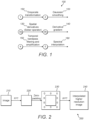
- Figure 1 demonstrates the motion magnification process 100 comprising the following steps:
- the acoustic field displaces the camera sufficiently to generate a blur in the camera image.
- This temporally modulated blur is detectable through a contrast detection algorithm.
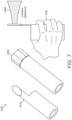
- Shown in Figures 3A and 3B are the actual motions of an optical camera type "Ausdom 1080p 12 M full HD", recorded by means of an accelerometer mounted on its body. These figures show that this motion magnification method successfully achieved visible results for sinusoidal displacements with amplitudes up to 2 micrometers peak-to-peak. This is shown as graph 300 in Figure 3A for a 40 kHz sinusoidal carrier amplitude-modulated at 5 Hz, and as graph 350 in Figure 3B , when the same carrier is amplitude-modulated at 100 Hz.
- a focused acoustic field was produced with a root means squared (RMS) pressure of about 1 kilopascal at 20 cm.
- RMS root means squared
- measuring contrast in fixed frame images from the motion-tracking camera may provide another method in quantifying distortion produced by the acoustic field.
- Contrast-detection algorithms are common in mirrorless cameras and other applications where phase detection is either too expensive or too bulky to implement. Contrast detection functions on the basic concept that a scene which is out of focus tends to blur objects and will cause adjacent pixels to average their values. This reduces contrast. By implementing a function which quantifies the contrast in an image, the camera system can move its lens to a position which maximizes this function and thereby will optimize its focus.
- Figure 4 shows an example of a set of images 400 that have varying levels of contrast from the least focused (lowest contrast) 410, to medium focused (middle contrast) 420, to the most focused (highest contrast) 430.
- the contrast detection as discussed herein will be used to quantify defocusing caused by the acoustic field.
- the shutter speed of the camera needs to be comparable to the period of modulation of the sound field. In this way, the image will be blurred by motion of the camera's focusing lens.
- Maximum defocusing minimum contrast
- the background which is being imaged during calibration needs to be as static as possible to avoid false minimums. Regions with possible changes such as shiny surfaces containing reflections could be excluded from analysis.
- Contrast quantifying algorithms include, but are not limited to, summed magnitude difference of adjacent pixels, summed magnitude squared difference of adjacent pixels, and summed magnitude difference of adjacent bins in the intensity histogram. Both grayscale and color information can be used.
- the ideal algorithmic implementation will depend on the variables including the camera used as well as the environment imaged during calibration.
- the final goal of the calibration process is to find the focus produced by phased array systems that maximizes the displacements of the camera apparatus.
- the decision on the final displacement and on displacement direction is based on the value of the gradient between different frames (or a sensible portion of the frame, e.g. where edges are more pronounced) of a video sequence.
- n refers to the frame
- N is the width of the frame
- M is the height of the frame
- ⁇ ( x , y ) n is the intensity of the pixel belonging to the x-th row, to the y-th column and to the n -th frame, after the motion magnification is performed (as explained in the previous section of this document).
- the function of merit for the contrast method is simply an application of the contrast formula deemed most effective in the application.
- the machine would ideally scan a portion of space where the camera is believed to exist.
- the machine could scan this portion of space following a regular pattern, since the space could be discretized in a regular grid of equally distant points with different x, y, z coordinates.
- the machine could scan the space in a random fashion, following a heuristic approach that resembles the Monte Carlo algorithm for optimization problems. Points to scan are sampled at random from an input probability distribution. For example, if a normal distribution is chosen, the mean could be the expected camera position and the standard deviation is chosen based on the expected variation in position derived from the manufacturing tolerances. The probability distribution would then be updated based on increasing knowledge of the camera location. Finally, the optimum point between the scanned ones is the focus which maximizes the value of the gradient algorithm M or minimizes the contrast.
- Mechanical resonators can be excited by ultrasound when the ultrasound is modulated at the resonant frequency. When enough energy is transferred and when operating at the correct frequency, a user in contact with the device can feel vibration near areas of largest displacement.
- the invention described herein exploits this effect to create devices that can produce haptic feedback while not carrying a battery or exciter when in the presence of an ultrasonic source.
- a simple resonator may be evaluated having a thin bar of rectangular cross section, with one dimension much smaller than the other two, and one much larger. Along the long dimension forms a series of modes related to the largest length. If the ends are left unclamped, they become anti-nodes and the frequencies supported by the rod are represented by sinusoids satisfying this condition with the displacement normal to the narrowest dimension.
- FIG. 5 Shown in Figure 5 is an illustration 500 of a simple bending rod haptic implement.
- Ultrasound 540 is incident on the right side of the device which creates bulk mechanical vibration 530 that can be felt by a user 510 touching or holding the device.
- This example illustrates the major features that will need to be adapted for the desired form-factor: a haptic region which the user is in contact with, whose displacement is felt, and a receive region which accepts activation from an ultrasonic source and is mechanically connected to the haptic region forming a resonator.
- the lowest order mode will have a node 520 (with zero-displacement) in the center of the rod and large displacement on the ends.
- a user may hold onto one end of the rod, leaving the other end exposed.
- Ultrasound modulated at the fundamental frequency of the resonator may be directed perpendicular to the rod on the other end.
- the rod vibrates, and the user 510 receives haptic feedback.
- This example neatly divides the device into two regions: a haptic region and a receive region.
- the haptic region is the area which is in contact with the user and is vibrating to give feedback to the user and is not necessarily always available for reception of ultrasound.
- the receive region also has large displacement but is designed to be continuously exposed to an ultrasonic source during operation.
- This example also illustrates possibilities for multiple-frequency of vibration in the same device: higher-order modes will be at higher frequencies, but the locations of largest-displacement will be similar (the ends).
- the ultrasonic source may be modulated at the desired frequency to change the feedback.
- multiple frequencies may be excited simultaneously to form sophisticated haptic waveforms. It should be noted that it is not necessary to have maximum displacement in the same location.
- a design may be implemented to have different frequencies target different locations.
- Design of haptic regions may focus on frequency and displacement. Frequencies may be selected to maximize the sensitivity of the nerves targeted. The fingers, for instance, range from 4 Hz to 400 Hz. Resonating at those frequencies for a hand-held device will maximize the sensitivity. Multiple frequencies may be combined to create distinct effects. Displacement is the fundamental attribute that dictates the strength of the haptic feedback and needs to be considered based on the application and strength desired. A textured surface may be present at one or more haptic regions to both attract the user's grip and potentially change the haptic feel.
- Design of receive regions should focus on direction of likely ultrasound, exposure, the area of the region, and quality-factor (Q-factor).
- Ultrasound carries momentum parallel to its direction of propagation.
- a receive region should be made of a high-acoustic-impedance material to reflect the pressure for maximum impulse transfer. The difference between the incident and reflected momentum vectors will be the imparted momentum to the resonator.
- a design may maximize the likelihood that this is parallel to the desired resonant mode displacement. This involves orienting the receive region towards the likely direction of incident ultrasound. Multiple receive regions may be included on the same device facing a variety of directions to maximize the likelihood of facing an acoustic array while the user is moving it.
- Figure 6 shows illustrations 900 of a stylus/pen form factor.
- the receive region is located at the rear of the implement where it is unlikely to be obstructed by the user.
- the incident ultrasound 930 causes mechanical excitation at the ends of the stylus/pen 970, 940, which produces haptic feel at the ends of the stylus/pen 960, 950.
- This vibration mode shown consists of oscillations only up and down within the plane of the diagram. If a user grasps around the pen perpendicular to this direction, he or she will receive a sheering force instead of the typical pushing force, giving a unique haptic sensation.
- Figure 7 shows illustrations 1000 of a potential handle-like haptic implement. This could be used to mimic the feel of a racket or bat for VR/AR applications. Shown are two variants of the receive region-an oval 1010 that is sensitive only to its normal direction and a multi-faceted receiver 1020 that can couple to ultrasound from a number of normal directions. The incident ultrasound 1040 causes the user 1030 to feel haptic effects.
- FIG. 8 an illustration 800 demonstrates the receive region is integrated seamlessly into the device by using any flat surface such as the edge of a knife 810.
- the incident ultrasound 820 is applied to the knife edge, causing mechanical excitation 840 on the opposite edge of the knife and producing haptic feel on both edges 830, 850.
- Q-factor relates to the time the resonator takes to ring up and ring down. This is influenced by the materials used (metal versus plastic versus rubber, etc.) as well as the attachment points and grip of the user.
- a large Q-factor (slow ring up and down) makes the device maximally sensitive to incident ultrasound but at the cost of precision-it will take more time to activate and deactivate the haptic. In that time, the user could move the implement away from the intended region of haptic feedback.
- a low-Q device can be very precise but will suffer from limited max amplitude when compared to the high-Q device. With sufficient ultrasonic energy, a low-Q device can be made both precise and strong enough for strong feedback.
- a high-Q device will likely work better. If well characterized, a high-Q device will have a predictable phase response to ultrasonic stimulus and could be driven out of phase to stop haptics to improve ring down.
- Figure 9 shows an illustration 600 of a passive haptic implement designed in the form factor of a tube that is to be grasped like a pen from the outer diameter 610 and designed to hold a stylus or pen.
- the pen/stylus 650 is inserted in the tube and secured along vibratory nodes 640.
- a receive area for the incident ultrasound 620 may protrude from the device.
- the pen/stylus could be used as normal.
- the haptic implement is excited with ultrasound, there is a flexing of the implement 630 and a haptic effect would be felt by the user.
- resonators will have some points of little-to-no movement frequently called “nulls” or “nodes” 640. These can serve as opportunities for attachment to other devices without losing energy into that device.
- the device is designed to have radial flexing modes to provide haptic and receive regions. Between these regions, nodes will exist which could provide an opportunity for attachment to a stylus or pen down the axis of the tube.
- the attachment may be designed to allow the stylus to slip in and out but still gripped securely enough to allow use. The sharper the contact point and the precision of the contact with the null minimizes the effect on the haptics.
- Excitation through modulation may be achieved with amplitude or spatio-temporal modulation.
- Amplitude modulation varies the pressure magnitude versus time, effectively turning it on and off at a given frequency or frequencies.
- Spatio-temporal modulation achieves the same stimulus at a given point by steering the intensity of the field away and then back again at the desired frequency.
- An amplitude modulated field may effectively activate a haptic region by simply being directed towards it, but by its nature eschews half of its power through modulation.
- the receive region may also be activated via spatiotemporal modulation by directing the field away from the receive region and back again. While away it could be used for direct mid-air haptics on the user or some other purpose.
- a haptic implement may be designed with two receive regions nearby each other but designed to be driven out of phase.
- Figure 10 shows an illustration of a possible spatiotemporal modulation excited haptic implement.
- the acoustic field 720 is directed to the end of the implement 710.
- the acoustic field 740 is directed to the middle of the implement 730. This allows continuous, full-power excitation of the implement.
- the ultrasound may be directed at one region, transitioned to the second, and then back again. This allows for the full power of the ultrasound source to be utilized at all times.
- the two haptic regions to be excited out of phase can be driven simultaneously with two amplitude modulated fields whose modulation is out of phase. This also allows for maximum utilization of available ultrasonic power.
- haptic implements thus far presume displacement normal to the surface of the implement and into the user.
- a passive implement may be designed which contains oscillations not entirely normal to the user contact. This provides a unique haptic experience relative to normal-oriented motion.
- a simple rod with the aspect ratio of a pencil could be designed with a flexing mode down its length (as in Figure 6 ).
- a flat is cut into one end as a receive region and oriented "up" and the flat is activated with ultrasound oriented "down,” this will cause displacement confined to a plane along the length of the rod and the up-down direction. If grasped along the sides of this imaginary plane, the user's fingers will experience displacement perpendicular to the skin.
- another flat is provided perpendicular to the first, it may be activated at the same frequency yet provide a unique haptic to the first activation region.
- Implements may be designed to be adjustable in their form. By rotating one end of the device through a joint (held mechanically or magnetically) the user may change the nature of the resonator. This may change the location of the haptic or receive regions. It may also affect the Q-factor, amplitude or resonant frequency. Besides rotation, the user may adjust a joint or any other form of mechanical connector.
- optimal coupling may be achieved by steering and/or focusing the ultrasound directly at the receive region of the haptic implement.
- tracking the receive regions efficiently may be necessary and can be designed into the implement.
- Options for tracking include, but are not limited to:
- Mechanical vibration may be harvested to power electronics using piezoelectric materials. By bonding a piezo film or crystal strategically to the implement, they could be hidden from view and not significantly affect haptics. In another arrangement, they could be used to aggressively change (or even completely stop) haptics by modulating their power draw. The power delivery could in this case, be independent of haptics.
- the energy can be temporarily stored and used to power any number of electronics on the device including but not limited to: displays, tracking emission/reception, and radios.
- Example form factors include:
Landscapes
- Engineering & Computer Science (AREA)
- General Engineering & Computer Science (AREA)
- Theoretical Computer Science (AREA)
- Physics & Mathematics (AREA)
- Human Computer Interaction (AREA)
- General Physics & Mathematics (AREA)
- Acoustics & Sound (AREA)
- Multimedia (AREA)
- User Interface Of Digital Computer (AREA)
- Measurement Of Velocity Or Position Using Acoustic Or Ultrasonic Waves (AREA)
- Measurement Of Mechanical Vibrations Or Ultrasonic Waves (AREA)
Description
- The present disclosure relates generally to acoustically-driven haptic effects in mid-air haptic systems.
- A continuous distribution of sound energy, referred to as an "acoustic field", may be used for a range of applications including haptic feedback in mid-air.
- Many applications for haptic feedback involve the vibrations originating from a device the user is holding. This can be as simple as a stylus which taps or vibrates to indicate a selection, or a handle meant to simulate a racket in virtual reality which vibrates as the user hits a (virtual) ball. Traditional approaches require an actuator imbedded in the device, a power source such as a battery, and some sort of controller which can activate the feedback at the appropriate time. This increases the cost of the device.
- An ultrasonic array for airborne haptic feedback offers enough energy to activate a new class of passive devices. With careful design, a small device can be designed to receive acoustic energy from the array and then vibrate to create haptic feedback without the need for any kind of active circuitry on the device. This saves cost and relieves the need to charge a battery.
-
US 2015/084929 A1 discloses a curved touch display apparatus for providing tactile feedback. The curved touch display comprises a curved screen, in which an image is displayed; and a projector including an infrared irradiator for irradiating infrared rays to the curved screen. An infrared camera photographs an infrared image reflected from the curved screen. An ultrasonic wave array module includes a plurality of ultrasonic wave generators which generate airborne ultrasonic waves. A controller determines a touched point on the curved screen based on the infrared image, and controls an operation of the ultrasonic wave array module to generate airborne ultrasonic waves directed to the touched point. - Aspects of the invention are described in accordance with the appended set of claims. In particular, mechanical resonators can be excited by ultrasound when it is modulated at the resonant frequency. When enough energy is transferred and when operating at the correct frequency, a user in contact with the device can feel vibration near areas of largest displacement. The invention described here exploits this effect to create devices which can produce haptic feedback while not carrying a battery or exciter when in the presence of an ultrasonic source.
- The examples of
Figures 1 to 4 and corresponding Section I "MOTION MAGNIFICATION", Section II "STILL-FRAME CONTRAST DETECTION", and Section III "MACHINE PATH AND DECISION MAKER" are not covered by the claims and are merely provided for illustration. - The accompanying figures, where like reference numerals refer to identical or functionally similar elements throughout the separate views, together with the detailed description below, are incorporated in and form part of the specification, serve to further illustrate embodiments of concepts that include the claimed invention and explain various principles and advantages of those embodiments.
-
Figure 1 shows a motion magnification process. -
Figure 2 shows the application of a Gaussian smoothing on an image. -
Figures 3A and 3B show graphs of motions of an optical camera. -
Figure 4 show text in various levels of focus. -
Figure 5 shows haptic effects on a bending rod. -
Figure 6 shows haptic effects on a pencil-shaped form factor. -
Figure 7 shows haptic effects on a handle-shaped form factor. -
Figure 8 shows haptic effects on a knife-shaped form factor -
Figure 9 shows haptic effects on an implement designed in the form factor of a tube that is to be grasped like a pen. -
Figure 10 shows an illustration of spatio-temporal modulated haptic implement. - Skilled artisans will appreciate that elements in the figures are illustrated for simplicity and clarity and have not necessarily been drawn to scale. For example, the dimensions of some of the elements in the figures may be exaggerated relative to other elements to help to improve understanding of embodiments of the present invention.
- The apparatus and method components have been represented where appropriate by conventional symbols in the drawings, showing only those specific details that are pertinent to understanding the embodiments of the present invention so as not to obscure the disclosure with details that will be readily apparent to those of ordinary skill in the art having the benefit of the description herein.
- As previously described, the magnification of the motion induced by the acoustic field on an optical camera can reveal small temporal variations in videos. The optical camera lens or camera chassis is excited with focused acoustic waves modulated at specific frequencies. These frequencies should be within the range of detectable frequencies of the optical camera, i.e., smaller than the sampling frequency of the camera. It is possible to apply different types of modulation (amplitude, frequency, phase) of the carrier to obtain the wanted frequency of excitation. The rationale of this method is to compare the amplified motion gradient produced by focal points at different spatial locations: the arrangement generating the largest gradient would give an estimation of the position of the camera. Once the relative position of the camera is determined, a calibration of the system may be performed.
- This approach combines spatial and temporal processing to amplify tiny motion of a video sequence. The process can be divided into five major steps, which are schematically summarized in the form of a flow diagram in
Figure 1 . Steps two and three are fundamental parts of the well-established Canny edge detector algorithm. The method comprises a first step in which each frame of the video is transformed into a grayscale, single-channel image for ease of processing, and a second step in which each frame is smoothed to remove inherent noise. Subsequently, the first derivative of each frame is computed to reveal edges. This has the aim of improving the detection of motion and sharpening the image. Eventually, a temporal bandpass filter is applied to isolate the motion generated by specific frequencies. The extracted signal is linearly amplified and then is added back to the original signal. A spectral interpolation can be used to further enhance subtle temporal changes between frames. -
Figure 1 demonstrates themotion magnification process 100 comprising the following steps: - 1. In
step 150, a grayscale transformation of the RGB frame in the case that a full color camera is used, based on one of the common grayscale algorithms (e.g. the Luma algorithm). If a camera that yields output that is a single channel to begin with is used, this step is skipped. - 2. In
step 120, the application of a Gaussian smoothing for each frame. The Gaussian smoothing operator is a 2-D spatial convolution operator that is used to "blur" images and remove both high-frequency detail and noise in both x and y directions. It uses a kernel that represents the shape of a Gaussian ("bell-shaped") hump, with the following form:

- 3. In
step 130, the application of a Sobel operator to each frame for the detection of edges. The Sobel operator is again a 2-D spatial convolution operator that performs a gradient measurement on an image and so emphasizes regions of high spatial frequency that correspond to edges. Instep 140, the Sobel operator can be obtained as the separable convolution of a Gaussian kernel in the direction(s) in which the edges are not to be detected and a differentiation kernel in the direction that crosses the edges to be detected, as follows:


for detecting pixels that cross edges in x and y respectively. For each image pixel, the gradient magnitude can be calculated by the formula:
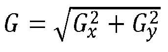
It is possible to obtain Sobel kernels ofsize 2 n-1 × 2 n-1 just by convolving the 3x3 kernel with another smoothingkernel n+ 1 times. - 4. In
step 150, the application of a bandpass temporal filter to extract the frequency bands of interest. The motion is magnified by altering some features of the video. The motion magnification is achieved by applying a bandpass temporal filter to the spatially filtered frames of the video. The bandpass filter needs to be chosen according to the frequency that one wants to magnify: it will be a range centered to the value of the carrier/modulation frequency, and in any case lower than the sampling frequency of the camera. The bandpass filtered signal then undergoes a process of linear amplification, before being added back to the original signal, as follows:

Where χ is an arbitrarily chosen constant, I(x, t) is the filtered signal and Ĩ(x, t) is the amplified signal. - 5. In
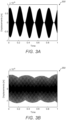
step 160, a two-dimensional spectral interpolation of data achieved by zero-padding in the frequency domain. This stage aims at increasing the sampling rate of each frame and subsequently at helping the recognition of motion. By performing interpolation on a frame sequence, the information held by the pixels of the original frames is transmitted at sub-pixel levels, allowing the possibility to perceive tinier movements. As shown inFigure 2 , thisprocess 200 is achieved by performing a 2D fast Fourier transform (FFT) 220 of theimage 210, followed by an appropriate zero padding of thehigher frequencies 230 and a2D inverse FFT 240. - It is possible to amplify and compare the magnified motion of the aliased frequencies, in the case of the carrier or the modulation frequency falling outside the range of detectable frequencies. As a rule of thumb, the range of frequencies to magnify should be as wide as possible.
- As shown by the accelerometer data, the acoustic field displaces the camera sufficiently to generate a blur in the camera image. This temporally modulated blur is detectable through a contrast detection algorithm. Shown in
Figures 3A and 3B are the actual motions of an optical camera type "Ausdom 1080p 12 M full HD", recorded by means of an accelerometer mounted on its body. These figures show that this motion magnification method successfully achieved visible results for sinusoidal displacements with amplitudes up to 2 micrometers peak-to-peak. This is shown asgraph 300 inFigure 3A for a 40 kHz sinusoidal carrier amplitude-modulated at 5 Hz, and asgraph 350 inFigure 3B , when the same carrier is amplitude-modulated at 100 Hz. A focused acoustic field was produced with a root means squared (RMS) pressure of about 1 kilopascal at 20 cm. - In some applications, measuring contrast in fixed frame images from the motion-tracking camera may provide another method in quantifying distortion produced by the acoustic field.
- Contrast-detection algorithms are common in mirrorless cameras and other applications where phase detection is either too expensive or too bulky to implement. Contrast detection functions on the basic concept that a scene which is out of focus tends to blur objects and will cause adjacent pixels to average their values. This reduces contrast. By implementing a function which quantifies the contrast in an image, the camera system can move its lens to a position which maximizes this function and thereby will optimize its focus.
Figure 4 shows an example of a set ofimages 400 that have varying levels of contrast from the least focused (lowest contrast) 410, to medium focused (middle contrast) 420, to the most focused (highest contrast) 430. - The contrast detection as discussed herein will be used to quantify defocusing caused by the acoustic field. The shutter speed of the camera needs to be comparable to the period of modulation of the sound field. In this way, the image will be blurred by motion of the camera's focusing lens. By comparing the contrast of the standard image without stimulation to the one with acoustic stimulation, one can quantify the effect of the acoustic field and progress towards optimal calibration. Maximum defocusing (minimum contrast) will correspond to a specific relative orientation and calibration will be possible. The background which is being imaged during calibration needs to be as static as possible to avoid false minimums. Regions with possible changes such as shiny surfaces containing reflections could be excluded from analysis.
- Contrast quantifying algorithms include, but are not limited to, summed magnitude difference of adjacent pixels, summed magnitude squared difference of adjacent pixels, and summed magnitude difference of adjacent bins in the intensity histogram. Both grayscale and color information can be used. The ideal algorithmic implementation will depend on the variables including the camera used as well as the environment imaged during calibration.
- The final goal of the calibration process is to find the focus produced by phased array systems that maximizes the displacements of the camera apparatus. The decision on the final displacement and on displacement direction is based on the value of the gradient between different frames (or a sensible portion of the frame, e.g. where edges are more pronounced) of a video sequence. A general gradient algorithm for decision making is the following for the motion magnification algorithm:

- The machine would ideally scan a portion of space where the camera is believed to exist. The machine could scan this portion of space following a regular pattern, since the space could be discretized in a regular grid of equally distant points with different x, y, z coordinates. Alternatively, the machine could scan the space in a random fashion, following a heuristic approach that resembles the Monte Carlo algorithm for optimization problems. Points to scan are sampled at random from an input probability distribution. For example, if a normal distribution is chosen, the mean could be the expected camera position and the standard deviation is chosen based on the expected variation in position derived from the manufacturing tolerances. The probability distribution would then be updated based on increasing knowledge of the camera location. Finally, the optimum point between the scanned ones is the focus which maximizes the value of the gradient algorithm M or minimizes the contrast.
- Mechanical resonators can be excited by ultrasound when the ultrasound is modulated at the resonant frequency. When enough energy is transferred and when operating at the correct frequency, a user in contact with the device can feel vibration near areas of largest displacement. The invention described herein exploits this effect to create devices that can produce haptic feedback while not carrying a battery or exciter when in the presence of an ultrasonic source.
- To illustrate this principle, a simple resonator may be evaluated having a thin bar of rectangular cross section, with one dimension much smaller than the other two, and one much larger. Along the long dimension forms a series of modes related to the largest length. If the ends are left unclamped, they become anti-nodes and the frequencies supported by the rod are represented by sinusoids satisfying this condition with the displacement normal to the narrowest dimension.
- Shown in
Figure 5 is anillustration 500 of a simple bending rod haptic implement.Ultrasound 540 is incident on the right side of the device which creates bulkmechanical vibration 530 that can be felt by auser 510 touching or holding the device. This example illustrates the major features that will need to be adapted for the desired form-factor: a haptic region which the user is in contact with, whose displacement is felt, and a receive region which accepts activation from an ultrasonic source and is mechanically connected to the haptic region forming a resonator. - The lowest order mode will have a node 520 (with zero-displacement) in the center of the rod and large displacement on the ends. In the context of this example, a user may hold onto one end of the rod, leaving the other end exposed. Ultrasound modulated at the fundamental frequency of the resonator may be directed perpendicular to the rod on the other end. When activated, the rod vibrates, and the
user 510 receives haptic feedback. This example neatly divides the device into two regions: a haptic region and a receive region. The haptic region is the area which is in contact with the user and is vibrating to give feedback to the user and is not necessarily always available for reception of ultrasound. The receive region also has large displacement but is designed to be continuously exposed to an ultrasonic source during operation. - This example also illustrates possibilities for multiple-frequency of vibration in the same device: higher-order modes will be at higher frequencies, but the locations of largest-displacement will be similar (the ends). As necessary, the ultrasonic source may be modulated at the desired frequency to change the feedback. Alternatively, multiple frequencies may be excited simultaneously to form sophisticated haptic waveforms. It should be noted that it is not necessary to have maximum displacement in the same location. A design may be implemented to have different frequencies target different locations.
- Design of haptic regions may focus on frequency and displacement. Frequencies may be selected to maximize the sensitivity of the nerves targeted. The fingers, for instance, range from 4 Hz to 400 Hz. Resonating at those frequencies for a hand-held device will maximize the sensitivity. Multiple frequencies may be combined to create distinct effects. Displacement is the fundamental attribute that dictates the strength of the haptic feedback and needs to be considered based on the application and strength desired. A textured surface may be present at one or more haptic regions to both attract the user's grip and potentially change the haptic feel.
- Design of receive regions should focus on direction of likely ultrasound, exposure, the area of the region, and quality-factor (Q-factor). Ultrasound carries momentum parallel to its direction of propagation. A receive region should be made of a high-acoustic-impedance material to reflect the pressure for maximum impulse transfer. The difference between the incident and reflected momentum vectors will be the imparted momentum to the resonator. A design may maximize the likelihood that this is parallel to the desired resonant mode displacement. This involves orienting the receive region towards the likely direction of incident ultrasound. Multiple receive regions may be included on the same device facing a variety of directions to maximize the likelihood of facing an acoustic array while the user is moving it.
-
Figure 6 showsillustrations 900 of a stylus/pen form factor. In this example, the receive region is located at the rear of the implement where it is unlikely to be obstructed by the user. Shown are two variants of the receive region, an oval 920 that receives from only one direction (normal) and ahexagon 910 that can receive from a multitude of normal directions. Theincident ultrasound 930 causes mechanical excitation at the ends of the stylus/pen pen -
Figure 7 showsillustrations 1000 of a potential handle-like haptic implement. This could be used to mimic the feel of a racket or bat for VR/AR applications. Shown are two variants of the receive region-an oval 1010 that is sensitive only to its normal direction and amulti-faceted receiver 1020 that can couple to ultrasound from a number of normal directions. Theincident ultrasound 1040 causes theuser 1030 to feel haptic effects. - The area of reflection integrates the available momentum transfer. If focused ultrasound is used, scaling the size of the receive region to match the expected focus waist will maximize the possible coupling. This is shown in
Figure 8 where anillustration 800 demonstrates the receive region is integrated seamlessly into the device by using any flat surface such as the edge of aknife 810. Theincident ultrasound 820 is applied to the knife edge, causingmechanical excitation 840 on the opposite edge of the knife and producing haptic feel on bothedges - Furthermore, Q-factor relates to the time the resonator takes to ring up and ring down. This is influenced by the materials used (metal versus plastic versus rubber, etc.) as well as the attachment points and grip of the user. A large Q-factor (slow ring up and down) makes the device maximally sensitive to incident ultrasound but at the cost of precision-it will take more time to activate and deactivate the haptic. In that time, the user could move the implement away from the intended region of haptic feedback. A low-Q device can be very precise but will suffer from limited max amplitude when compared to the high-Q device. With sufficient ultrasonic energy, a low-Q device can be made both precise and strong enough for strong feedback. If ultrasonic energy is limited in the intended environment, a high-Q device will likely work better. If well characterized, a high-Q device will have a predictable phase response to ultrasonic stimulus and could be driven out of phase to stop haptics to improve ring down.
-
Figure 9 shows anillustration 600 of a passive haptic implement designed in the form factor of a tube that is to be grasped like a pen from theouter diameter 610 and designed to hold a stylus or pen. The pen/stylus 650 is inserted in the tube and secured alongvibratory nodes 640. A receive area for theincident ultrasound 620 may protrude from the device. When a user grasps the implement, the pen/stylus could be used as normal. When the haptic implement is excited with ultrasound, there is a flexing of the implement 630 and a haptic effect would be felt by the user. - Most resonators will have some points of little-to-no movement frequently called "nulls" or "nodes" 640. These can serve as opportunities for attachment to other devices without losing energy into that device. The device is designed to have radial flexing modes to provide haptic and receive regions. Between these regions, nodes will exist which could provide an opportunity for attachment to a stylus or pen down the axis of the tube. The attachment may be designed to allow the stylus to slip in and out but still gripped securely enough to allow use. The sharper the contact point and the precision of the contact with the null minimizes the effect on the haptics.
- Excitation through modulation may be achieved with amplitude or spatio-temporal modulation. Amplitude modulation varies the pressure magnitude versus time, effectively turning it on and off at a given frequency or frequencies. Spatio-temporal modulation achieves the same stimulus at a given point by steering the intensity of the field away and then back again at the desired frequency. An amplitude modulated field may effectively activate a haptic region by simply being directed towards it, but by its nature eschews half of its power through modulation.
- The receive region may also be activated via spatiotemporal modulation by directing the field away from the receive region and back again. While away it could be used for direct mid-air haptics on the user or some other purpose.
- Alternatively, a haptic implement may be designed with two receive regions nearby each other but designed to be driven out of phase.
Figure 10 shows an illustration of a possible spatiotemporal modulation excited haptic implement. For the first half of thevibratory cycle 700, theacoustic field 720 is directed to the end of the implement 710. For the second half of thecycle 750 theacoustic field 740 is directed to the middle of the implement 730. This allows continuous, full-power excitation of the implement. In this way, the ultrasound may be directed at one region, transitioned to the second, and then back again. This allows for the full power of the ultrasound source to be utilized at all times. In another arrangement, the two haptic regions to be excited out of phase can be driven simultaneously with two amplitude modulated fields whose modulation is out of phase. This also allows for maximum utilization of available ultrasonic power. - Descriptions of haptic implements thus far presume displacement normal to the surface of the implement and into the user. In another arrangement, a passive implement may be designed which contains oscillations not entirely normal to the user contact. This provides a unique haptic experience relative to normal-oriented motion. As an example, a simple rod with the aspect ratio of a pencil could be designed with a flexing mode down its length (as in
Figure 6 ). When a flat is cut into one end as a receive region and oriented "up" and the flat is activated with ultrasound oriented "down," this will cause displacement confined to a plane along the length of the rod and the up-down direction. If grasped along the sides of this imaginary plane, the user's fingers will experience displacement perpendicular to the skin. If another flat is provided perpendicular to the first, it may be activated at the same frequency yet provide a unique haptic to the first activation region. - Implements may be designed to be adjustable in their form. By rotating one end of the device through a joint (held mechanically or magnetically) the user may change the nature of the resonator. This may change the location of the haptic or receive regions. It may also affect the Q-factor, amplitude or resonant frequency. Besides rotation, the user may adjust a joint or any other form of mechanical connector.
- In regions with limited but steerable ultrasound, optimal coupling may be achieved by steering and/or focusing the ultrasound directly at the receive region of the haptic implement. In this application, tracking the receive regions efficiently may be necessary and can be designed into the implement. Options for tracking include, but are not limited to:
- Visual or IR fiducials placed on the implement that are designed to be recognized and tracked by a camera system. This can take the form of a simple sticker or as sophisticated as a retroreflector which will light up when exposed to incident light.
- A specific acoustic reflecting shape contained on the implement which forms a recognizable reflection. The reflected acoustic signal would be recorded with microphones placed in the area which would identify and track the implement. This can be as simple as a flat reflector or some shape which forms a structured reflection field.
- A powered element within the implement that provides tracking information. This may be a Bluetooth or some similar wireless protocol. Tracking information may be determined with a pickup mic to detect the receive ultrasound. It may be a vibration pickup to measure the haptic receive. The element can emit light or some other form of electromagnetic radiation which is picked up with external receivers. Alternatively, it can pick up and interpret tracking information provided by scanning base stations or similar structured information. Accelerometer data may be captured and transmitted as well.
- Mechanical vibration may be harvested to power electronics using piezoelectric materials. By bonding a piezo film or crystal strategically to the implement, they could be hidden from view and not significantly affect haptics. In another arrangement, they could be used to aggressively change (or even completely stop) haptics by modulating their power draw. The power delivery could in this case, be independent of haptics. The energy can be temporarily stored and used to power any number of electronics on the device including but not limited to: displays, tracking emission/reception, and radios.
- Example form factors include:
- A rod intended to emulate a pen or scalpel.
- A tube which is designed to have a stylus inserted.
- A larger tube or rod meant to emulate the size and shape the handle of a racket, golf club, or bat (as in
Figure 7 ). - A glove with resonators placed in various places such as the back of the hand which are not as sensitive to traditional mid-air haptics.
- A face mask.
- A full-body suit with many different resonators matched to the specific locations on the body.
- A game piece, figurine, model, or toy.
- While the foregoing descriptions disclose specific values, any other specific values may be used to achieve similar results. Further, the various features of the foregoing embodiments may be selected and combined to produce numerous variations of improved haptic systems.
- In the foregoing specification, specific embodiments have been described. However, one of ordinary skill in the art appreciates that various modifications and changes can be made without departing from the scope of the invention as set forth in the claims below. Accordingly, the specification and figures are to be regarded in an illustrative rather than a restrictive sense, and all such modifications are intended to be included within the scope of present teachings.
- Moreover, in this document, relational terms such as first and second, top and bottom, and the like may be used solely to distinguish one entity or action from another entity or action without necessarily requiring or implying any actual such relationship or order between such entities or actions. The terms "comprises," "comprising," "has", "having," "includes", "including," "contains", "containing" or any other variation thereof, are intended to cover a non-exclusive inclusion, such that a process, method, article, or apparatus that comprises, has, includes, contains a list of elements does not include only those elements but may include other elements not expressly listed or inherent to such process, method, article, or apparatus. An element proceeded by "comprises ... a", "has ... a", "includes ... a", "contains ... a" does not, without more constraints, preclude the existence of additional identical elements in the process, method, article, or apparatus that comprises, has, includes, contains the element. The terms "a" and "an" are defined as one or more unless explicitly stated otherwise herein. The terms "substantially", "essentially", "approximately", "about" or any other version thereof, are defined as being close to as understood by one of ordinary skill in the art. The term "coupled" as used herein is defined as connected, although not necessarily directly and not necessarily mechanically. A device or structure that is "configured" in a certain way is configured in at least that way but may also be configured in ways that are not listed.
- The Abstract of the Disclosure is provided to allow the reader to quickly ascertain the nature of the technical disclosure. It is submitted with the understanding that it will not be used to interpret or limit the scope or meaning of the claims. In addition, in the foregoing Detailed Description, it can be seen that various features are grouped together in various embodiments for the purpose of streamlining the disclosure. This method of disclosure is not to be interpreted as reflecting an intention that the claimed embodiments require more features than are expressly recited in each claim. Rather, as the following claims reflect, inventive subject matter lies in less than all features of a single disclosed embodiment. Thus, the following claims are hereby incorporated into the Detailed Description, with each claim standing on its own as a separately claimed subject matter.
Claims (12)
- A method comprising:receiving acoustic energy (540) from an ultrasonic source at a modulatedfrequency on a first surface of a device, the device having at least one mechanical resonant frequency equivalent to the modulated frequency;vibrating a second surface of the device, distinct from the first surface, as a result of the acoustic energy;providing haptic feedback to a user (510) by vibrating the second surface of the device.
- The method as in claim 1, wherein the device has multiple resonant frequencies.
- The method as in claim 2, wherein each of at least two of the multiple resonant frequencies causes haptic effects at a unique location on the device.
- The method as in claim 2, wherein each of at least two of the multiple resonant frequencies are received at a unique location on the device.
- The method as in claim 1, further comprising:
attaching the device to a second device through mechanical nodes - The method as in claim 1, wherein the acoustic energy at the modulatedfrequency comprises a plurality of signals having varying phases, and whereineach of the plurality of signals having varying phases is received at a unique location on the device.
- The method as in claim 1, wherein a quality factor of the device is manipulated by the user.
- The method as in claim 1, wherein a quality factor of the device is manipulated by the acoustic field.
- The method as in claim 1, wherein the haptic feedback is perpendicular to a contact of the user.
- The method as in claim 1, further comprising:
harvesting energy from the vibrating of the second surface of the device. - The method as in claim 10, wherein the energy is harvested using an attached piezoelectric material.
- The method as in claim 10 wherein the energy is used to power electronics embedded in the device.
Applications Claiming Priority (4)
| Application Number | Priority Date | Filing Date | Title |
|---|---|---|---|
| US201762590609P | 2017-11-26 | 2017-11-26 | |
| US201862691130P | 2018-06-28 | 2018-06-28 | |
| EP18811906.9A EP3714352B1 (en) | 2017-11-26 | 2018-11-26 | Haptic effects from focused acoustic fields |
| PCT/GB2018/053404 WO2019102220A1 (en) | 2017-11-26 | 2018-11-26 | Haptic effects from focused acoustic fields |
Related Parent Applications (2)
| Application Number | Title | Priority Date | Filing Date |
|---|---|---|---|
| EP18811906.9A Division EP3714352B1 (en) | 2017-11-26 | 2018-11-26 | Haptic effects from focused acoustic fields |
| EP18811906.9A Division-Into EP3714352B1 (en) | 2017-11-26 | 2018-11-26 | Haptic effects from focused acoustic fields |
Publications (2)
| Publication Number | Publication Date |
|---|---|
| EP4047454A1 EP4047454A1 (en) | 2022-08-24 |
| EP4047454B1 true EP4047454B1 (en) | 2023-08-09 |
Family
ID=64564913
Family Applications (2)
| Application Number | Title | Priority Date | Filing Date |
|---|---|---|---|
| EP18811906.9A Active EP3714352B1 (en) | 2017-11-26 | 2018-11-26 | Haptic effects from focused acoustic fields |
| EP22165812.3A Active EP4047454B1 (en) | 2017-11-26 | 2018-11-26 | Haptic effects from focused acoustic fields |
Family Applications Before (1)
| Application Number | Title | Priority Date | Filing Date |
|---|---|---|---|
| EP18811906.9A Active EP3714352B1 (en) | 2017-11-26 | 2018-11-26 | Haptic effects from focused acoustic fields |
Country Status (3)
| Country | Link |
|---|---|
| US (2) | US11531395B2 (en) |
| EP (2) | EP3714352B1 (en) |
| WO (1) | WO2019102220A1 (en) |
Families Citing this family (32)
| Publication number | Priority date | Publication date | Assignee | Title |
|---|---|---|---|---|
| GB2513884B (en) | 2013-05-08 | 2015-06-17 | Univ Bristol | Method and apparatus for producing an acoustic field |
| GB2530036A (en) | 2014-09-09 | 2016-03-16 | Ultrahaptics Ltd | Method and apparatus for modulating haptic feedback |
| US10101811B2 (en) | 2015-02-20 | 2018-10-16 | Ultrahaptics Ip Ltd. | Algorithm improvements in a haptic system |
| WO2016132144A1 (en) | 2015-02-20 | 2016-08-25 | Ultrahaptics Ip Limited | Perceptions in a haptic system |
| US10818162B2 (en) | 2015-07-16 | 2020-10-27 | Ultrahaptics Ip Ltd | Calibration techniques in haptic systems |
| US10268275B2 (en) | 2016-08-03 | 2019-04-23 | Ultrahaptics Ip Ltd | Three-dimensional perceptions in haptic systems |
| US10943578B2 (en) | 2016-12-13 | 2021-03-09 | Ultrahaptics Ip Ltd | Driving techniques for phased-array systems |
| US11531395B2 (en) | 2017-11-26 | 2022-12-20 | Ultrahaptics Ip Ltd | Haptic effects from focused acoustic fields |
| US11704983B2 (en) | 2017-12-22 | 2023-07-18 | Ultrahaptics Ip Ltd | Minimizing unwanted responses in haptic systems |
| WO2019122912A1 (en) | 2017-12-22 | 2019-06-27 | Ultrahaptics Limited | Tracking in haptic systems |
| SG11202010752VA (en) | 2018-05-02 | 2020-11-27 | Ultrahaptics Ip Ltd | Blocking plate structure for improved acoustic transmission efficiency |
| US11098951B2 (en) | 2018-09-09 | 2021-08-24 | Ultrahaptics Ip Ltd | Ultrasonic-assisted liquid manipulation |
| WO2020131020A1 (en) * | 2018-12-17 | 2020-06-25 | Emerge Now Inc. | Systems for interfacing with immersive computing environments |
| US12373033B2 (en) | 2019-01-04 | 2025-07-29 | Ultrahaptics Ip Ltd | Mid-air haptic textures |
| WO2020141330A2 (en) | 2019-01-04 | 2020-07-09 | Ultrahaptics Ip Ltd | Mid-air haptic textures |
| US11842517B2 (en) | 2019-04-12 | 2023-12-12 | Ultrahaptics Ip Ltd | Using iterative 3D-model fitting for domain adaptation of a hand-pose-estimation neural network |
| US11374586B2 (en) | 2019-10-13 | 2022-06-28 | Ultraleap Limited | Reducing harmonic distortion by dithering |
| JP7611244B2 (en) | 2019-10-13 | 2025-01-09 | ウルトラリープ リミテッド | Dynamic Capping with Virtual Microphone |
| US11715453B2 (en) | 2019-12-25 | 2023-08-01 | Ultraleap Limited | Acoustic transducer structures |
| US12061351B2 (en) * | 2020-04-15 | 2024-08-13 | Universal City Studios Llc | Interactive object systems and methods |
| US11816267B2 (en) | 2020-06-23 | 2023-11-14 | Ultraleap Limited | Features of airborne ultrasonic fields |
| KR102332318B1 (en) * | 2020-07-22 | 2021-12-01 | 이화여자대학교 산학협력단 | Method and system for providing a roughness haptic of a virtual object using spatiotemporal encoding |
| US11886639B2 (en) | 2020-09-17 | 2024-01-30 | Ultraleap Limited | Ultrahapticons |
| CN112562631B (en) * | 2020-11-17 | 2022-04-26 | 深圳先进技术研究院 | Method and system for generating acoustic tweezers |
| EP4030268B1 (en) * | 2021-01-15 | 2024-08-07 | Société BIC | Writing instruments, methods and systems comprising the same |
| US12517585B2 (en) | 2021-07-15 | 2026-01-06 | Ultraleap Limited | Control point manipulation techniques in haptic systems |
| US12008286B2 (en) * | 2021-11-19 | 2024-06-11 | Apple Inc. | Peripheral device with acoustic resonator |
| US11681373B1 (en) * | 2021-12-08 | 2023-06-20 | International Business Machines Corporation | Finger movement management with haptic feedback in touch-enabled devices |
| US12366923B2 (en) | 2022-09-26 | 2025-07-22 | Pison Technology, Inc. | Systems and methods for gesture inference using ML model selection |
| US12366920B2 (en) | 2022-09-26 | 2025-07-22 | Pison Technology, Inc. | Systems and methods for gesture inference using transformations |
| US12340627B2 (en) | 2022-09-26 | 2025-06-24 | Pison Technology, Inc. | System and methods for gesture inference using computer vision |
| US12502110B2 (en) | 2023-10-24 | 2025-12-23 | Pison Technology, Inc. | Systems and methods for determining physiological state based on surface biopotentials |
Family Cites Families (320)
| Publication number | Priority date | Publication date | Assignee | Title |
|---|---|---|---|---|
| US4218921A (en) | 1979-07-13 | 1980-08-26 | The United States Of America As Represented By The Administrator Of The National Aeronautics And Space Administration | Method and apparatus for shaping and enhancing acoustical levitation forces |
| CA1175359A (en) | 1981-01-30 | 1984-10-02 | John G. Martner | Arrayed ink jet apparatus |
| FR2551611B1 (en) | 1983-08-31 | 1986-10-24 | Labo Electronique Physique | NOVEL ULTRASONIC TRANSDUCER STRUCTURE AND ULTRASONIC ECHOGRAPHY MEDIA EXAMINATION APPARATUS COMPRISING SUCH A STRUCTURE |
| JPS6067718U (en) | 1983-10-17 | 1985-05-14 | 株式会社吉野工業所 | compact container |
| EP0309003B1 (en) | 1984-02-15 | 1994-12-07 | Trw Inc. | Surface acoustic wave spectrum analyzer |
| JPS62258597A (en) | 1986-04-25 | 1987-11-11 | Yokogawa Medical Syst Ltd | Ultrasonic transducer |
| US4760525A (en) | 1986-06-10 | 1988-07-26 | The United States Of America As Represented By The Secretary Of The Air Force | Complex arithmetic vector processor for performing control function, scalar operation, and set-up of vector signal processing instruction |
| US5226000A (en) | 1988-11-08 | 1993-07-06 | Wadia Digital Corporation | Method and system for time domain interpolation of digital audio signals |
| US5235986A (en) | 1990-02-12 | 1993-08-17 | Acuson Corporation | Variable origin-variable angle acoustic scanning method and apparatus for a curved linear array |
| EP0528910A4 (en) | 1990-05-14 | 1993-12-22 | Commonwealth Scientific And Industrial Research Organization | A coupling device |
| DE59100463D1 (en) | 1991-02-07 | 1993-11-11 | Siemens Ag | Method of manufacturing ultrasonic transducers. |
| US5243344A (en) | 1991-05-30 | 1993-09-07 | Koulopoulos Michael A | Digital-to-analog converter--preamplifier apparatus |
| JP3243821B2 (en) | 1992-02-27 | 2002-01-07 | ヤマハ株式会社 | Electronic musical instrument |
| US5371834A (en) | 1992-08-28 | 1994-12-06 | The United States Of America As Represented By The Administrator Of The National Aeronautics And Space Administration | Adaptive neuron model--an architecture for the rapid learning of nonlinear topological transformations |
| US6216538B1 (en) | 1992-12-02 | 2001-04-17 | Hitachi, Ltd. | Particle handling apparatus for handling particles in fluid by acoustic radiation pressure |
| US5426388A (en) | 1994-02-15 | 1995-06-20 | The Babcock & Wilcox Company | Remote tone burst electromagnetic acoustic transducer pulser |
| US5477736A (en) | 1994-03-14 | 1995-12-26 | General Electric Company | Ultrasonic transducer with lens having electrorheological fluid therein for dynamically focusing and steering ultrasound energy |
| US5511296A (en) | 1994-04-08 | 1996-04-30 | Hewlett Packard Company | Method for making integrated matching layer for ultrasonic transducers |
| US5583405A (en) | 1994-08-11 | 1996-12-10 | Nabco Limited | Automatic door opening and closing system |
| AU6162596A (en) | 1995-06-05 | 1996-12-24 | Christian Constantinov | Ultrasonic sound system and method for producing virtual sou nd |
| US5729694A (en) | 1996-02-06 | 1998-03-17 | The Regents Of The University Of California | Speech coding, reconstruction and recognition using acoustics and electromagnetic waves |
| US7225404B1 (en) | 1996-04-04 | 2007-05-29 | Massachusetts Institute Of Technology | Method and apparatus for determining forces to be applied to a user through a haptic interface |
| US5859915A (en) | 1997-04-30 | 1999-01-12 | American Technology Corporation | Lighted enhanced bullhorn |
| US6193936B1 (en) | 1998-11-09 | 2001-02-27 | Nanogram Corporation | Reactant delivery apparatuses |
| US6029518A (en) | 1997-09-17 | 2000-02-29 | The United States Of America As Represented By The Administrator Of The National Aeronautics And Space Administration | Manipulation of liquids using phased array generation of acoustic radiation pressure |
| US7391872B2 (en) | 1999-04-27 | 2008-06-24 | Frank Joseph Pompei | Parametric audio system |
| US6647359B1 (en) | 1999-07-16 | 2003-11-11 | Interval Research Corporation | System and method for synthesizing music by scanning real or simulated vibrating object |
| US6307302B1 (en) | 1999-07-23 | 2001-10-23 | Measurement Specialities, Inc. | Ultrasonic transducer having impedance matching layer |
| WO2001023104A2 (en) | 1999-09-29 | 2001-04-05 | 1...Limited | Method and apparatus to direct sound using an array of output transducers |
| US6771294B1 (en) | 1999-12-29 | 2004-08-03 | Petri Pulli | User interface |
| US6925187B2 (en) | 2000-03-28 | 2005-08-02 | American Technology Corporation | Horn array emitter |
| US6503204B1 (en) | 2000-03-31 | 2003-01-07 | Acuson Corporation | Two-dimensional ultrasonic transducer array having transducer elements in a non-rectangular or hexagonal grid for medical diagnostic ultrasonic imaging and ultrasound imaging system using same |
| US7284027B2 (en) | 2000-05-15 | 2007-10-16 | Qsigma, Inc. | Method and apparatus for high speed calculation of non-linear functions and networks using non-linear function calculations for digital signal processing |
| DE10026077B4 (en) | 2000-05-25 | 2007-03-22 | Siemens Ag | Beamforming method |
| DE10051133A1 (en) | 2000-10-16 | 2002-05-02 | Siemens Ag | Beamforming method |
| US6768921B2 (en) | 2000-12-28 | 2004-07-27 | Z-Tech (Canada) Inc. | Electrical impedance method and apparatus for detecting and diagnosing diseases |
| US7463249B2 (en) | 2001-01-18 | 2008-12-09 | Illinois Tool Works Inc. | Acoustic wave touch actuated switch with feedback |
| US7058147B2 (en) | 2001-02-28 | 2006-06-06 | At&T Corp. | Efficient reduced complexity windowed optimal time domain equalizer for discrete multitone-based DSL modems |
| WO2002100480A2 (en) | 2001-06-13 | 2002-12-19 | Apple Marc G | Brachytherapy device and method |
| US6436051B1 (en) | 2001-07-20 | 2002-08-20 | Ge Medical Systems Global Technology Company, Llc | Electrical connection system for ultrasonic receiver array |
| US6758094B2 (en) | 2001-07-31 | 2004-07-06 | Koninklijke Philips Electronics, N.V. | Ultrasonic transducer wafer having variable acoustic impedance |
| WO2003019125A1 (en) | 2001-08-31 | 2003-03-06 | Nanyang Techonological University | Steering of directional sound beams |
| US7623114B2 (en) | 2001-10-09 | 2009-11-24 | Immersion Corporation | Haptic feedback sensations based on audio output from computer devices |
| EP1461598B1 (en) | 2001-12-13 | 2014-04-02 | UNIVERSITY OF WYOMING RESEARCH CORPORATION, doing business as, WESTERN RESEARCH INSTITUTE | Volatile organic compound sensor system |
| CA2474257A1 (en) | 2002-01-18 | 2003-08-07 | American Technology Corporation | Modulator- amplifier |
| US6800987B2 (en) | 2002-01-22 | 2004-10-05 | Measurement Specialties, Inc. | Protective housing for ultrasonic transducer apparatus |
| US20030182647A1 (en) | 2002-03-19 | 2003-09-25 | Radeskog Mattias Dan | Automatic interactive component placement for electronics-CAD software through the use of force simulations |
| US7272073B2 (en) | 2002-05-27 | 2007-09-18 | Sonicemotion Ag | Method and device for generating information relating to the relative position of a set of at least three acoustic transducers |
| US20040052387A1 (en) | 2002-07-02 | 2004-03-18 | American Technology Corporation. | Piezoelectric film emitter configuration |
| US7720229B2 (en) | 2002-11-08 | 2010-05-18 | University Of Maryland | Method for measurement of head related transfer functions |
| GB0301093D0 (en) | 2003-01-17 | 2003-02-19 | 1 Ltd | Set-up method for array-type sound systems |
| JP4192672B2 (en) | 2003-05-16 | 2008-12-10 | 株式会社日本自動車部品総合研究所 | Ultrasonic sensor |
| US7190496B2 (en) | 2003-07-24 | 2007-03-13 | Zebra Imaging, Inc. | Enhanced environment visualization using holographic stereograms |
| WO2005017965A2 (en) | 2003-08-06 | 2005-02-24 | Measurement Specialities, Inc. | Ultrasonic air transducer arrays using polymer piezoelectric films and impedance matching structures for ultrasonic polymer transducer arrays |
| DE10342263A1 (en) | 2003-09-11 | 2005-04-28 | Infineon Technologies Ag | Optoelectronic component and optoelectronic arrangement with an optoelectronic component |
| US20050148874A1 (en) | 2003-12-19 | 2005-07-07 | Brock-Fisher George A. | Ultrasonic imaging aberration correction with microbeamforming |
| WO2005062729A2 (en) | 2003-12-27 | 2005-07-14 | Electronics And Telecommunications Research Institute | A mimo-ofdm system using eigenbeamforming method |
| US20050212760A1 (en) | 2004-03-23 | 2005-09-29 | Marvit David L | Gesture based user interface supporting preexisting symbols |
| WO2005098731A2 (en) | 2004-03-29 | 2005-10-20 | German Peter T | Systems and methods to determine elastic properties of materials |
| NZ551334A (en) | 2004-05-17 | 2008-07-31 | Epos Technologies Ltd | Acoustic robust synchronization signalling for acoustic positioning system |
| US7689639B2 (en) | 2004-06-04 | 2010-03-30 | Telefonaktiebolaget Lm Ericsson (Publ) | Complex logarithmic ALU |
| US7865236B2 (en) | 2004-10-20 | 2011-01-04 | Nervonix, Inc. | Active electrode, bio-impedance based, tissue discrimination system and methods of use |
| US7138620B2 (en) | 2004-10-29 | 2006-11-21 | Silicon Light Machines Corporation | Two-dimensional motion sensor |
| US20060090955A1 (en) | 2004-11-04 | 2006-05-04 | George Cardas | Microphone diaphragms defined by logarithmic curves and microphones for use therewith |
| US7692661B2 (en) | 2005-01-26 | 2010-04-06 | Pixar | Method of creating and evaluating bandlimited noise for computer graphics |
| WO2006086743A2 (en) | 2005-02-09 | 2006-08-17 | American Technology Corporation | In-band parametric sound generation system |
| US7345600B1 (en) | 2005-03-09 | 2008-03-18 | Texas Instruments Incorporated | Asynchronous sampling rate converter |
| GB0508194D0 (en) | 2005-04-22 | 2005-06-01 | The Technology Partnership Plc | Pump |
| US9459632B2 (en) | 2005-06-27 | 2016-10-04 | Coactive Drive Corporation | Synchronized array of vibration actuators in a network topology |
| WO2015006467A1 (en) | 2013-07-09 | 2015-01-15 | Coactive Drive Corporation | Synchronized array of vibration actuators in an integrated module |
| US7233722B2 (en) * | 2005-08-15 | 2007-06-19 | General Display, Ltd. | System and method for fiber optics based direct view giant screen flat panel display |
| US20080226088A1 (en) | 2005-09-20 | 2008-09-18 | Koninklijke Philips Electronics, N.V. | Audio Transducer System |
| US8000481B2 (en) | 2005-10-12 | 2011-08-16 | Yamaha Corporation | Speaker array and microphone array |
| US20070094317A1 (en) | 2005-10-25 | 2007-04-26 | Broadcom Corporation | Method and system for B-spline interpolation of a one-dimensional signal using a fractional interpolation ratio |
| US8312479B2 (en) | 2006-03-08 | 2012-11-13 | Navisense | Application programming interface (API) for sensory events |
| US8405618B2 (en) | 2006-03-24 | 2013-03-26 | Northwestern University | Haptic device with indirect haptic feedback |
| DE102007020593A1 (en) * | 2006-05-01 | 2007-11-08 | Ident Technology Ag | input device |
| CN101466432A (en) | 2006-06-14 | 2009-06-24 | 皇家飞利浦电子股份有限公司 | Device for transdermal drug delivery and method for operating such a device |
| US7425874B2 (en) | 2006-06-30 | 2008-09-16 | Texas Instruments Incorporated | All-digital phase-locked loop for a digital pulse-width modulator |
| US7497662B2 (en) | 2006-07-31 | 2009-03-03 | General Electric Company | Methods and systems for assembling rotatable machines |
| US20100030076A1 (en) | 2006-08-01 | 2010-02-04 | Kobi Vortman | Systems and Methods for Simultaneously Treating Multiple Target Sites |
| JP2008074075A (en) | 2006-09-25 | 2008-04-03 | Canon Inc | Image forming apparatus and control method thereof |
| DE502007001104D1 (en) | 2006-10-09 | 2009-09-03 | Baumer Electric Ag | Ultrasonic transducer with acoustic impedance matching |
| WO2008064230A2 (en) | 2006-11-20 | 2008-05-29 | Personics Holdings Inc. | Methods and devices for hearing damage notification and intervention ii |
| US8351646B2 (en) | 2006-12-21 | 2013-01-08 | Honda Motor Co., Ltd. | Human pose estimation and tracking using label assignment |
| KR100889726B1 (en) | 2007-02-02 | 2009-03-24 | 한국전자통신연구원 | Tactile stimulation device and device using the same |
| FR2912817B1 (en) | 2007-02-21 | 2009-05-22 | Super Sonic Imagine Sa | METHOD FOR OPTIMIZING WAVE FOCUSING THROUGH AN INTRODUCING ELEMENT OF ABERATIONS |
| DE102007018266A1 (en) | 2007-04-10 | 2008-10-16 | Seereal Technologies S.A. | Holographic projection system with optical waveguide tracking and means for correcting the holographic reconstruction |
| US8269168B1 (en) | 2007-04-30 | 2012-09-18 | Physical Logic Ag | Meta materials integration, detection and spectral analysis |
| US9100748B2 (en) | 2007-05-04 | 2015-08-04 | Bose Corporation | System and method for directionally radiating sound |
| US9317110B2 (en) | 2007-05-29 | 2016-04-19 | Cfph, Llc | Game with hand motion control |
| EP2096309A4 (en) | 2007-10-16 | 2013-02-27 | Murata Manufacturing Co | Piezoelectric micro-blower |
| FR2923612B1 (en) | 2007-11-12 | 2011-05-06 | Super Sonic Imagine | INSONIFYING DEVICE COMPRISING A THREE-DIMENSIONAL NETWORK OF SPIRAL EMITTERS PROVIDED TO GENERATE A HIGH-INTENSITY FOCUSED WAVE BEAM |
| FI20075879A0 (en) | 2007-12-05 | 2007-12-05 | Valtion Teknillinen | Device for measuring pressure, sound pressure variation, magnetic field, acceleration, vibration and gas composition |
| EP2219528A1 (en) | 2007-12-13 | 2010-08-25 | Koninklijke Philips Electronics N.V. | Robotic ultrasound system with microadjustment and positioning control using feedback responsive to acquired image data |
| GB0804739D0 (en) | 2008-03-14 | 2008-04-16 | The Technology Partnership Plc | Pump |
| US20090251421A1 (en) | 2008-04-08 | 2009-10-08 | Sony Ericsson Mobile Communications Ab | Method and apparatus for tactile perception of digital images |
| US8369973B2 (en) | 2008-06-19 | 2013-02-05 | Texas Instruments Incorporated | Efficient asynchronous sample rate conversion |
| US20100013613A1 (en) | 2008-07-08 | 2010-01-21 | Jonathan Samuel Weston | Haptic feedback projection system |
| JP5496192B2 (en) | 2008-07-08 | 2014-05-21 | ブリュエル アンド ケアー サウンド アンド ヴァイブレーション メジャーメント エー/エス | Method for reconstructing an acoustic field |
| US8162840B2 (en) | 2008-07-16 | 2012-04-24 | Syneron Medical Ltd | High power ultrasound transducer |
| GB2464117B (en) | 2008-10-03 | 2015-01-28 | Hiwave Technologies Uk Ltd | Touch sensitive device |
| JP2010109579A (en) | 2008-10-29 | 2010-05-13 | Nippon Telegr & Teleph Corp <Ntt> | Sound output element array and sound output method |
| US8199953B2 (en) | 2008-10-30 | 2012-06-12 | Avago Technologies Wireless Ip (Singapore) Pte. Ltd. | Multi-aperture acoustic horn |
| US9569001B2 (en) | 2009-02-03 | 2017-02-14 | Massachusetts Institute Of Technology | Wearable gestural interface |
| US10564721B2 (en) | 2009-03-12 | 2020-02-18 | Immersion Corporation | Systems and methods for using multiple actuators to realize textures |
| JP5477736B2 (en) | 2009-03-25 | 2014-04-23 | 独立行政法人放射線医学総合研究所 | Particle beam irradiation equipment |
| US8442246B2 (en) | 2009-04-28 | 2013-05-14 | Panasonic Corporation | Hearing aid device and hearing aid method |
| US8009022B2 (en) | 2009-05-29 | 2011-08-30 | Microsoft Corporation | Systems and methods for immersive interaction with virtual objects |
| MX2011012975A (en) | 2009-06-03 | 2012-04-02 | The Technology Partnership Plc | Fluid disc pump. |
| US7920078B2 (en) | 2009-06-19 | 2011-04-05 | Conexant Systems, Inc. | Systems and methods for variable rate conversion |
| EP2271129A1 (en) | 2009-07-02 | 2011-01-05 | Nxp B.V. | Transducer with resonant cavity |
| KR20110005587A (en) * | 2009-07-10 | 2011-01-18 | 삼성전자주식회사 | Method and apparatus for generating vibration of a mobile terminal |
| US20110010958A1 (en) | 2009-07-16 | 2011-01-20 | Wayne Clark | Quiet hair dryer |
| US9177543B2 (en) | 2009-08-26 | 2015-11-03 | Insightec Ltd. | Asymmetric ultrasound phased-array transducer for dynamic beam steering to ablate tissues in MRI |
| GB0916707D0 (en) | 2009-09-23 | 2009-11-04 | Elliptic Laboratories As | Acoustic motion determination |
| US8027224B2 (en) | 2009-11-11 | 2011-09-27 | Brown David A | Broadband underwater acoustic transducer |
| EP2510404B1 (en) | 2009-12-11 | 2019-05-22 | Sorama Holding B.V. | Acoustic transducer assembly |
| JP5681727B2 (en) | 2009-12-28 | 2015-03-11 | コーニンクレッカ フィリップス エヌ ヴェ | Optimization of high-density focused ultrasonic transducer |
| KR20110093379A (en) | 2010-02-12 | 2011-08-18 | 주식회사 팬택 | Apparatus and method therefor, channel status information feedback, transmission method of base station |
| US20110199342A1 (en) | 2010-02-16 | 2011-08-18 | Harry Vartanian | Apparatus and method for providing elevated, indented or texturized sensations to an object near a display device or input detection using ultrasound |
| JP5457874B2 (en) | 2010-02-19 | 2014-04-02 | 日本電信電話株式会社 | Local reproduction apparatus, method and program |
| US9357280B2 (en) | 2010-04-20 | 2016-05-31 | Nokia Technologies Oy | Apparatus having an acoustic display |
| US20130046213A1 (en) | 2010-05-05 | 2013-02-21 | Technion Research & Development Foundation Ltd. | Method and system of manipulating bilayer membranes |
| US8519982B2 (en) | 2010-06-21 | 2013-08-27 | Sony Corporation | Active acoustic touch location for electronic devices |
| NZ587483A (en) | 2010-08-20 | 2012-12-21 | Ind Res Ltd | Holophonic speaker system with filters that are pre-configured based on acoustic transfer functions |
| JP5343946B2 (en) | 2010-08-25 | 2013-11-13 | 株式会社デンソー | Tactile presentation device |
| US8782109B2 (en) | 2010-09-10 | 2014-07-15 | Texas Instruments Incorporated | Asynchronous sample rate conversion using a polynomial interpolator with minimax stopband attenuation |
| US8607922B1 (en) | 2010-09-10 | 2013-12-17 | Harman International Industries, Inc. | High frequency horn having a tuned resonant cavity |
| US8422721B2 (en) | 2010-09-14 | 2013-04-16 | Frank Rizzello | Sound reproduction systems and method for arranging transducers therein |
| KR101221513B1 (en) | 2010-12-13 | 2013-01-21 | 가천대학교 산학협력단 | Graphic haptic electronic board and method for transferring visual information to visually impaired people as haptic information |
| DE102011017250B4 (en) | 2011-01-07 | 2022-12-01 | Maxim Integrated Products, Inc. | Touch feedback system, haptic feedback system, and method for providing haptic feedback |
| US9076429B2 (en) | 2011-01-31 | 2015-07-07 | Wayne State University | Acoustic metamaterials |
| GB201101870D0 (en) | 2011-02-03 | 2011-03-23 | The Technology Partnership Plc | Pump |
| JP5961246B2 (en) | 2011-03-22 | 2016-08-02 | コーニンクレッカ フィリップス エヌ ヴェKoninklijke Philips N.V. | Ultrasonic CMUT with suppressed acoustic coupling to the substrate |
| JP5367001B2 (en) | 2011-03-24 | 2013-12-11 | ツインバード工業株式会社 | Hairdryer |
| US10061387B2 (en) | 2011-03-31 | 2018-08-28 | Nokia Technologies Oy | Method and apparatus for providing user interfaces |
| US8937603B2 (en) | 2011-04-01 | 2015-01-20 | Analog Devices, Inc. | Method and apparatus for haptic vibration response profiling and feedback |
| US10152116B2 (en) | 2011-04-26 | 2018-12-11 | The Regents Of The University Of California | Systems and devices for recording and reproducing senses |
| US8833510B2 (en) | 2011-05-05 | 2014-09-16 | Massachusetts Institute Of Technology | Phononic metamaterials for vibration isolation and focusing of elastic waves |
| US9421291B2 (en) | 2011-05-12 | 2016-08-23 | Fifth Third Bank | Hand dryer with sanitizing ionization assembly |
| US20120299853A1 (en) | 2011-05-26 | 2012-11-29 | Sumit Dagar | Haptic interface |
| KR101290763B1 (en) | 2011-06-08 | 2013-07-29 | 가천대학교 산학협력단 | System and method for providing learning information for visually impaired people based on haptic electronic board |
| WO2013018579A1 (en) | 2011-08-03 | 2013-02-07 | 株式会社村田製作所 | Ultrasound transducer |
| US9417754B2 (en) | 2011-08-05 | 2016-08-16 | P4tents1, LLC | User interface system, method, and computer program product |
| US20150209564A1 (en) | 2011-09-02 | 2015-07-30 | Drexel University | Ultrasound device and therapeutic methods |
| WO2013093906A1 (en) | 2011-09-19 | 2013-06-27 | Eyesight Mobile Technologies Ltd. | Touch free interface for augmented reality systems |
| WO2013042021A1 (en) | 2011-09-22 | 2013-03-28 | Koninklijke Philips Electronics N.V. | Ultrasound measurement assembly for multidirectional measurement |
| US9143879B2 (en) | 2011-10-19 | 2015-09-22 | James Keith McElveen | Directional audio array apparatus and system |
| US20130100008A1 (en) | 2011-10-19 | 2013-04-25 | Stefan J. Marti | Haptic Response Module |
| PL2818478T3 (en) | 2011-10-28 | 2017-09-29 | Regeneron Pharmaceuticals, Inc. | Humanized IL-6 and IL-6 receptor |
| KR101355532B1 (en) | 2011-11-21 | 2014-01-24 | 알피니언메디칼시스템 주식회사 | High Intensity Focused Ultrasound Transducer |
| CA2859045A1 (en) * | 2011-12-29 | 2013-07-04 | Mighty Cast, Inc. | Interactive base and token capable of communicating with computing device |
| US8711118B2 (en) | 2012-02-15 | 2014-04-29 | Immersion Corporation | Interactivity model for shared feedback on mobile devices |
| US8493354B1 (en) | 2012-08-23 | 2013-07-23 | Immersion Corporation | Interactivity model for shared feedback on mobile devices |
| US20120223880A1 (en) | 2012-02-15 | 2012-09-06 | Immersion Corporation | Method and apparatus for producing a dynamic haptic effect |
| KR102046102B1 (en) | 2012-03-16 | 2019-12-02 | 삼성전자주식회사 | Artificial atom and Metamaterial and Device including the same |
| US8570296B2 (en) | 2012-05-16 | 2013-10-29 | Immersion Corporation | System and method for display of multiple data channels on a single haptic display |
| GB201208853D0 (en) | 2012-05-18 | 2012-07-04 | Hiwave Technologies Uk Ltd | Panel for use in vibratory panel device |
| CN104349849B (en) | 2012-05-31 | 2017-07-21 | 皇家飞利浦有限公司 | Ultrasound transducer assembly and method for driving ultrasonic transducer head |
| WO2013184746A1 (en) | 2012-06-08 | 2013-12-12 | A.L.M Holding Company | Biodiesel emulsion for cleaning bituminous coated equipment |
| EP2702935A1 (en) | 2012-08-29 | 2014-03-05 | Agfa HealthCare N.V. | System and method for optical coherence tomography and positioning element |
| US9552673B2 (en) | 2012-10-17 | 2017-01-24 | Microsoft Technology Licensing, Llc | Grasping virtual objects in augmented reality |
| IL223086A (en) | 2012-11-18 | 2017-09-28 | Noveto Systems Ltd | Method and system for generation of sound fields |
| US8947387B2 (en) | 2012-12-13 | 2015-02-03 | Immersion Corporation | System and method for identifying users and selecting a haptic response |
| US9459697B2 (en) | 2013-01-15 | 2016-10-04 | Leap Motion, Inc. | Dynamic, free-space user interactions for machine control |
| US9202313B2 (en) | 2013-01-21 | 2015-12-01 | Microsoft Technology Licensing, Llc | Virtual interaction with image projection |
| US12453853B2 (en) | 2013-01-21 | 2025-10-28 | Cala Health, Inc. | Multi-modal stimulation for treating tremor |
| US9323397B2 (en) | 2013-03-11 | 2016-04-26 | The Regents Of The University Of California | In-air ultrasonic rangefinding and angle estimation |
| US9208664B1 (en) | 2013-03-11 | 2015-12-08 | Amazon Technologies, Inc. | Adjusting structural characteristics of a device |
| WO2014140538A1 (en) | 2013-03-13 | 2014-09-18 | Bae Systems Plc | A metamaterial |
| WO2014153007A1 (en) | 2013-03-14 | 2014-09-25 | Revive Electronics, LLC | Methods and apparatuses for drying electronic devices |
| US9436282B2 (en) | 2013-03-14 | 2016-09-06 | Immersion Corporation | Contactor-based haptic feedback generation |
| US9886941B2 (en) | 2013-03-15 | 2018-02-06 | Elwha Llc | Portable electronic device directed audio targeted user system and method |
| US9647464B2 (en) | 2013-03-15 | 2017-05-09 | Fujifilm Sonosite, Inc. | Low noise power sources for portable electronic systems |
| US10181314B2 (en) | 2013-03-15 | 2019-01-15 | Elwha Llc | Portable electronic device directed audio targeted multiple user system and method |
| US20170238807A9 (en) | 2013-03-15 | 2017-08-24 | LX Medical, Inc. | Tissue imaging and image guidance in luminal anatomic structures and body cavities |
| US20140269214A1 (en) | 2013-03-15 | 2014-09-18 | Elwha LLC, a limited liability company of the State of Delaware | Portable electronic device directed audio targeted multi-user system and method |
| US20140269207A1 (en) | 2013-03-15 | 2014-09-18 | Elwha Llc | Portable Electronic Device Directed Audio Targeted User System and Method |
| US10291983B2 (en) | 2013-03-15 | 2019-05-14 | Elwha Llc | Portable electronic device directed audio system and method |
| WO2014176528A1 (en) | 2013-04-26 | 2014-10-30 | Immersion Corporation | Passive stiffness and active deformation haptic output devices for flexible displays |
| GB2513884B (en) | 2013-05-08 | 2015-06-17 | Univ Bristol | Method and apparatus for producing an acoustic field |
| JP6505089B2 (en) | 2013-06-12 | 2019-04-24 | アトラス・コプコ・インダストリアル・テクニーク・アクチボラグ | Method of ultrasonically measuring the elongation of a fastener performed by a power tool and a power tool |
| US9804675B2 (en) | 2013-06-27 | 2017-10-31 | Elwha Llc | Tactile feedback generated by non-linear interaction of surface acoustic waves |
| US8884927B1 (en) | 2013-06-27 | 2014-11-11 | Elwha Llc | Tactile feedback generated by phase conjugation of ultrasound surface acoustic waves |
| US20150006645A1 (en) | 2013-06-28 | 2015-01-01 | Jerry Oh | Social sharing of video clips |
| WO2014209405A1 (en) | 2013-06-29 | 2014-12-31 | Intel Corporation | System and method for adaptive haptic effects |
| GB2516820A (en) | 2013-07-01 | 2015-02-11 | Nokia Corp | An apparatus |
| US20150019299A1 (en) | 2013-07-12 | 2015-01-15 | Joseph Harvey | Method of Generating Golf Index Reports |
| US10228242B2 (en) | 2013-07-12 | 2019-03-12 | Magic Leap, Inc. | Method and system for determining user input based on gesture |
| US10359857B2 (en) | 2013-07-18 | 2019-07-23 | Immersion Corporation | Usable hidden controls with haptic feedback |
| KR101484230B1 (en) | 2013-07-24 | 2015-01-16 | 현대자동차 주식회사 | Touch display device for vehicle and driving method thereof |
| JP2015035657A (en) | 2013-08-07 | 2015-02-19 | 株式会社豊田中央研究所 | Notification device and input device |
| US9576084B2 (en) | 2013-08-27 | 2017-02-21 | Halliburton Energy Services, Inc. | Generating a smooth grid for simulating fluid flow in a well system environment |
| US9576445B2 (en) | 2013-09-06 | 2017-02-21 | Immersion Corp. | Systems and methods for generating haptic effects associated with an envelope in audio signals |
| US20150078136A1 (en) | 2013-09-13 | 2015-03-19 | Mitsubishi Heavy Industries, Ltd. | Conformable Transducer With Self Position Sensing |
| WO2015039622A1 (en) | 2013-09-19 | 2015-03-26 | The Hong Kong University Of Science And Technology | Active control of membrane-type acoustic metamaterial |
| KR101550601B1 (en) | 2013-09-25 | 2015-09-07 | 현대자동차 주식회사 | Curved touch display apparatus for providing tactile feedback and method thereof |
| DK2863654T3 (en) | 2013-10-17 | 2018-10-22 | Oticon As | Method for reproducing an acoustic sound field |
| EP3175791B1 (en) | 2013-11-04 | 2021-09-08 | Ecential Robotics | Method for reconstructing a 3d image from 2d x-ray images |
| GB201322103D0 (en) | 2013-12-13 | 2014-01-29 | The Technology Partnership Plc | Fluid pump |
| US9366588B2 (en) | 2013-12-16 | 2016-06-14 | Lifescan, Inc. | Devices, systems and methods to determine area sensor |
| US9612658B2 (en) | 2014-01-07 | 2017-04-04 | Ultrahaptics Ip Ltd | Method and apparatus for providing tactile sensations |
| JP6311197B2 (en) | 2014-02-13 | 2018-04-18 | 本田技研工業株式会社 | Sound processing apparatus and sound processing method |
| US9945818B2 (en) | 2014-02-23 | 2018-04-17 | Qualcomm Incorporated | Ultrasonic authenticating button |
| US10203762B2 (en) | 2014-03-11 | 2019-02-12 | Magic Leap, Inc. | Methods and systems for creating virtual and augmented reality |
| US9679197B1 (en) | 2014-03-13 | 2017-06-13 | Leap Motion, Inc. | Biometric aware object detection and tracking |
| US9649558B2 (en) | 2014-03-14 | 2017-05-16 | Sony Interactive Entertainment Inc. | Gaming device with rotatably placed cameras |
| KR101464327B1 (en) | 2014-03-27 | 2014-11-25 | 연세대학교 산학협력단 | Apparatus, system and method for providing air-touch feedback |
| KR20150118813A (en) | 2014-04-15 | 2015-10-23 | 삼성전자주식회사 | Providing Method for Haptic Information and Electronic Device supporting the same |
| US20150323667A1 (en) | 2014-05-12 | 2015-11-12 | Chirp Microsystems | Time of flight range finding with an adaptive transmit pulse and adaptive receiver processing |
| US10579207B2 (en) | 2014-05-14 | 2020-03-03 | Purdue Research Foundation | Manipulating virtual environment using non-instrumented physical object |
| US10198030B2 (en) | 2014-05-15 | 2019-02-05 | Federal Express Corporation | Wearable devices for courier processing and methods of use thereof |
| CN103984414B (en) | 2014-05-16 | 2018-12-25 | 北京智谷睿拓技术服务有限公司 | The method and apparatus for generating tactile feedback |
| EP3769618A1 (en) | 2014-06-09 | 2021-01-27 | Terumo BCT, Inc. | Lyophilization container |
| US10569300B2 (en) | 2014-06-17 | 2020-02-25 | Pixie Dust Technologies, Inc. | Low-noise ultrasonic wave focusing apparatus |
| KR101687017B1 (en) | 2014-06-25 | 2016-12-16 | 한국과학기술원 | Hand localization system and the method using head worn RGB-D camera, user interaction system |
| FR3023036A1 (en) | 2014-06-27 | 2016-01-01 | Orange | RE-SAMPLING BY INTERPOLATION OF AUDIO SIGNAL FOR LOW-LATER CODING / DECODING |
| WO2016007920A1 (en) | 2014-07-11 | 2016-01-14 | New York University | Three dimensional tactile feedback system |
| KR101659050B1 (en) | 2014-07-14 | 2016-09-23 | 한국기계연구원 | Air-coupled ultrasonic transducer using metamaterials |
| US9600083B2 (en) | 2014-07-15 | 2017-03-21 | Immersion Corporation | Systems and methods to generate haptic feedback for skin-mediated interactions |
| JP2016035646A (en) | 2014-08-01 | 2016-03-17 | 株式会社デンソー | Tactile device and tactile display having the same |
| US9525944B2 (en) | 2014-08-05 | 2016-12-20 | The Boeing Company | Apparatus and method for an active and programmable acoustic metamaterial |
| GB2530036A (en) | 2014-09-09 | 2016-03-16 | Ultrahaptics Ltd | Method and apparatus for modulating haptic feedback |
| WO2016073936A2 (en) | 2014-11-07 | 2016-05-12 | Chirp Microsystems | Package waveguide for acoustic sensor with electronic delay compensation |
| US10427034B2 (en) | 2014-12-17 | 2019-10-01 | Igt Canada Solutions Ulc | Contactless tactile feedback on gaming terminal with 3D display |
| CA2875033C (en) | 2014-12-17 | 2022-07-26 | Fayez Idris | Contactless tactile feedback on gaming terminal with 3d display |
| NL2014025B1 (en) | 2014-12-19 | 2016-10-12 | Umc Utrecht Holding Bv | High intensity focused ultrasound apparatus. |
| US9779713B2 (en) | 2014-12-24 | 2017-10-03 | United Technologies Corporation | Acoustic metamaterial gate |
| GB2539368A (en) | 2015-02-09 | 2016-12-21 | Univ Erasmus Med Ct Rotterdam | Intravascular photoacoustic imaging |
| US10101811B2 (en) | 2015-02-20 | 2018-10-16 | Ultrahaptics Ip Ltd. | Algorithm improvements in a haptic system |
| WO2016132144A1 (en) | 2015-02-20 | 2016-08-25 | Ultrahaptics Ip Limited | Perceptions in a haptic system |
| US9911232B2 (en) | 2015-02-27 | 2018-03-06 | Microsoft Technology Licensing, Llc | Molding and anchoring physically constrained virtual environments to real-world environments |
| EP3266224B1 (en) | 2015-04-08 | 2021-05-19 | Huawei Technologies Co., Ltd. | Apparatus and method for driving an array of loudspeakers |
| CN108883335A (en) | 2015-04-14 | 2018-11-23 | 约翰·詹姆斯·丹尼尔斯 | Wearable electronic multisensory interfaces for man-machine or man-man |
| AU2016100399B4 (en) * | 2015-04-17 | 2017-02-02 | Apple Inc. | Contracting and elongating materials for providing input and output for an electronic device |
| WO2016182832A1 (en) | 2015-05-08 | 2016-11-17 | Ut-Battelle, Llc | Dryer using high frequency vibration |
| US9919069B2 (en) | 2015-05-24 | 2018-03-20 | LivOnyx Inc. | Systems and methods for sanitizing surfaces |
| US10210858B2 (en) | 2015-06-30 | 2019-02-19 | Pixie Dust Technologies, Inc. | System and method for manipulating objects in a computational acoustic-potential field |
| US10818162B2 (en) | 2015-07-16 | 2020-10-27 | Ultrahaptics Ip Ltd | Calibration techniques in haptic systems |
| US9865072B2 (en) | 2015-07-23 | 2018-01-09 | Disney Enterprises, Inc. | Real-time high-quality facial performance capture |
| US10313012B2 (en) | 2015-08-03 | 2019-06-04 | Phase Sensitive Innovations, Inc. | Distributed array for direction and frequency finding |
| US10416306B2 (en) | 2015-08-17 | 2019-09-17 | Texas Instruments Incorporated | Methods and apparatus to measure and analyze vibration signatures |
| US11106273B2 (en) | 2015-10-30 | 2021-08-31 | Ostendo Technologies, Inc. | System and methods for on-body gestural interfaces and projection displays |
| US10318008B2 (en) | 2015-12-15 | 2019-06-11 | Purdue Research Foundation | Method and system for hand pose detection |
| US20170181725A1 (en) | 2015-12-25 | 2017-06-29 | General Electric Company | Joint ultrasound imaging system and method |
| US11189140B2 (en) | 2016-01-05 | 2021-11-30 | Ultrahaptics Ip Ltd | Calibration and detection techniques in haptic systems |
| US9818294B2 (en) | 2016-01-06 | 2017-11-14 | Honda Motor Co., Ltd. | System for indicating vehicle presence and method thereof |
| EP3207817A1 (en) | 2016-02-17 | 2017-08-23 | Koninklijke Philips N.V. | Ultrasound hair drying and styling |
| CN107179826B (en) | 2016-03-11 | 2021-08-31 | 松下知识产权经营株式会社 | Gesture input system and gesture input method |
| US10091344B2 (en) | 2016-03-28 | 2018-10-02 | International Business Machines Corporation | Displaying virtual target window on mobile device based on user intent |
| US10877559B2 (en) | 2016-03-29 | 2020-12-29 | Intel Corporation | System to provide tactile feedback during non-contact interaction |
| US9936324B2 (en) | 2016-04-04 | 2018-04-03 | Pixie Dust Technologies, Inc. | System and method for generating spatial sound using ultrasound |
| US9667173B1 (en) | 2016-04-26 | 2017-05-30 | Turtle Beach Corporation | Electrostatic parametric transducer and related methods |
| US10228758B2 (en) | 2016-05-20 | 2019-03-12 | Disney Enterprises, Inc. | System for providing multi-directional and multi-person walking in virtual reality environments |
| US10140776B2 (en) | 2016-06-13 | 2018-11-27 | Microsoft Technology Licensing, Llc | Altering properties of rendered objects via control points |
| US10531212B2 (en) | 2016-06-17 | 2020-01-07 | Ultrahaptics Ip Ltd. | Acoustic transducers in haptic systems |
| US10268275B2 (en) | 2016-08-03 | 2019-04-23 | Ultrahaptics Ip Ltd | Three-dimensional perceptions in haptic systems |
| US10755538B2 (en) | 2016-08-09 | 2020-08-25 | Ultrahaptics ilP LTD | Metamaterials and acoustic lenses in haptic systems |
| EP3496608A4 (en) | 2016-08-15 | 2020-03-18 | Georgia Tech Research Corporation | ELECTRONIC DEVICE AND ITS CONTROL METHOD |
| US10394317B2 (en) | 2016-09-15 | 2019-08-27 | International Business Machines Corporation | Interaction with holographic image notification |
| US10945080B2 (en) | 2016-11-18 | 2021-03-09 | Stages Llc | Audio analysis and processing system |
| US10373452B2 (en) | 2016-11-29 | 2019-08-06 | Immersion Corporation | Targeted haptic projection |
| US10943578B2 (en) | 2016-12-13 | 2021-03-09 | Ultrahaptics Ip Ltd | Driving techniques for phased-array systems |
| WO2018109505A1 (en) | 2016-12-15 | 2018-06-21 | Google Llc | Transforming source domain images into target domain images |
| US10497358B2 (en) | 2016-12-23 | 2019-12-03 | Ultrahaptics Ip Ltd | Transducer driver |
| US10839591B2 (en) | 2017-01-04 | 2020-11-17 | Nvidia Corporation | Stereoscopic rendering using raymarching and a virtual view broadcaster for such rendering |
| US10289909B2 (en) | 2017-03-06 | 2019-05-14 | Xerox Corporation | Conditional adaptation network for image classification |
| JP6239796B1 (en) | 2017-04-05 | 2017-11-29 | 京セラ株式会社 | Electronics |
| US20180304310A1 (en) | 2017-04-24 | 2018-10-25 | Ultrahaptics Ip Ltd | Interference Reduction Techniques in Haptic Systems |
| US20190197840A1 (en) | 2017-04-24 | 2019-06-27 | Ultrahaptics Ip Ltd | Grouping and Optimization of Phased Ultrasonic Transducers for Multi-Field Solutions |
| WO2018200424A1 (en) | 2017-04-24 | 2018-11-01 | Ultrahaptics Ip Ltd | Algorithm enhancements for haptic-based phased-array systems |
| US10469973B2 (en) | 2017-04-28 | 2019-11-05 | Bose Corporation | Speaker array systems |
| EP3409380A1 (en) * | 2017-05-31 | 2018-12-05 | Nxp B.V. | Acoustic processor |
| US10168782B1 (en) | 2017-06-05 | 2019-01-01 | Rockwell Collins, Inc. | Ultrasonic haptic feedback control system and method |
| CN107340871A (en) | 2017-07-25 | 2017-11-10 | 深识全球创新科技(北京)有限公司 | The devices and methods therefor and purposes of integrated gesture identification and ultrasonic wave touch feedback |
| US11048329B1 (en) | 2017-07-27 | 2021-06-29 | Emerge Now Inc. | Mid-air ultrasonic haptic interface for immersive computing environments |
| US10327974B2 (en) * | 2017-08-02 | 2019-06-25 | Immersion Corporation | Haptic implants |
| US10535174B1 (en) | 2017-09-14 | 2020-01-14 | Electronic Arts Inc. | Particle-based inverse kinematic rendering system |
| US10512839B2 (en) | 2017-09-28 | 2019-12-24 | Igt | Interacting with three-dimensional game elements using gaze detection |
| US10593101B1 (en) | 2017-11-01 | 2020-03-17 | Facebook Technologies, Llc | Marker based tracking |
| US11531395B2 (en) | 2017-11-26 | 2022-12-20 | Ultrahaptics Ip Ltd | Haptic effects from focused acoustic fields |
| WO2019113380A1 (en) | 2017-12-06 | 2019-06-13 | Invensense, Inc. | Three dimensional object-localization and tracking using ultrasonic pulses with synchronized inertial position determination |
| KR102742177B1 (en) | 2017-12-22 | 2024-12-11 | 울트라햅틱스 아이피 엘티디 | Human interactions with airborne haptic systems |
| WO2019122912A1 (en) | 2017-12-22 | 2019-06-27 | Ultrahaptics Limited | Tracking in haptic systems |
| US11704983B2 (en) | 2017-12-22 | 2023-07-18 | Ultrahaptics Ip Ltd | Minimizing unwanted responses in haptic systems |
| US11175739B2 (en) | 2018-01-26 | 2021-11-16 | Immersion Corporation | Method and device for performing actuator control based on an actuator model |
| US20190310710A1 (en) | 2018-04-04 | 2019-10-10 | Ultrahaptics Limited | Dynamic Haptic Feedback Systems |
| SG11202010752VA (en) | 2018-05-02 | 2020-11-27 | Ultrahaptics Ip Ltd | Blocking plate structure for improved acoustic transmission efficiency |
| CN112385142B (en) | 2018-05-11 | 2024-04-05 | 纳诺塞米有限公司 | Digital compensator for nonlinear systems |
| CN109101111B (en) | 2018-08-24 | 2021-01-29 | 吉林大学 | A tactile reproduction method and device integrating electrostatic force, air pressure film and mechanical vibration |
| JP7014100B2 (en) | 2018-08-27 | 2022-02-01 | 日本電信電話株式会社 | Expansion equipment, expansion method and expansion program |
| US10915792B2 (en) | 2018-09-06 | 2021-02-09 | Nec Corporation | Domain adaptation for instance detection and segmentation |
| US11098951B2 (en) | 2018-09-09 | 2021-08-24 | Ultrahaptics Ip Ltd | Ultrasonic-assisted liquid manipulation |
| WO2020049322A1 (en) | 2018-09-09 | 2020-03-12 | Ultrahaptics Ip Limited | Event triggering in phased-array systems |
| US11378997B2 (en) | 2018-10-12 | 2022-07-05 | Ultrahaptics Ip Ltd | Variable phase and frequency pulse-width modulation technique |
| CN109523526B (en) | 2018-11-08 | 2021-10-22 | 腾讯科技(深圳)有限公司 | Tissue nodule detection and its model training method, device, equipment and system |
| US10599434B1 (en) | 2018-12-14 | 2020-03-24 | Raytheon Company | Providing touch gesture recognition to a legacy windowed software application |
| KR102756358B1 (en) | 2018-12-18 | 2025-01-17 | 삼성전자주식회사 | Detector, method of object detection, learning apparatus, and learning method for domain transformation |
| KR102230421B1 (en) | 2018-12-28 | 2021-03-22 | 한국과학기술원 | Apparatus and method of controlling virtual model |
| WO2020141330A2 (en) | 2019-01-04 | 2020-07-09 | Ultrahaptics Ip Ltd | Mid-air haptic textures |
| KR102791242B1 (en) | 2019-02-13 | 2025-04-09 | 현대자동차주식회사 | Gesture interface system for autonomous vehicle and operating method thereof |
| US11475246B2 (en) | 2019-04-02 | 2022-10-18 | Synthesis Ai, Inc. | System and method for generating training data for computer vision systems based on image segmentation |
| US11842517B2 (en) | 2019-04-12 | 2023-12-12 | Ultrahaptics Ip Ltd | Using iterative 3D-model fitting for domain adaptation of a hand-pose-estimation neural network |
| US11374586B2 (en) | 2019-10-13 | 2022-06-28 | Ultraleap Limited | Reducing harmonic distortion by dithering |
| US20210109712A1 (en) | 2019-10-13 | 2021-04-15 | Ultraleap Limited | Hardware Algorithm for Complex-Valued Exponentiation and Logarithm Using Simplified Sub-Steps |
| JP7611244B2 (en) | 2019-10-13 | 2025-01-09 | ウルトラリープ リミテッド | Dynamic Capping with Virtual Microphone |
| US11169610B2 (en) | 2019-11-08 | 2021-11-09 | Ultraleap Limited | Tracking techniques in haptic systems |
| US11715453B2 (en) | 2019-12-25 | 2023-08-01 | Ultraleap Limited | Acoustic transducer structures |
| US12400753B2 (en) | 2020-03-30 | 2025-08-26 | University Of Florida Research Foundation, Inc. | Collaborative feature ensembling adaptation for domain adaptation in unsupervised optic disc and cup segmentation |
| US20210303758A1 (en) | 2020-03-31 | 2021-09-30 | Ultraleap Limited | Accelerated Hardware Using Dual Quaternions |
| US11816267B2 (en) | 2020-06-23 | 2023-11-14 | Ultraleap Limited | Features of airborne ultrasonic fields |
| US11301090B2 (en) | 2020-07-30 | 2022-04-12 | Ncr Corporation | Methods, system, and apparatus for touchless terminal interface interaction |
| US11886639B2 (en) | 2020-09-17 | 2024-01-30 | Ultraleap Limited | Ultrahapticons |
| US20220155949A1 (en) | 2020-11-16 | 2022-05-19 | Ultraleap Limited | Intent Driven Dynamic Gesture Recognition System |
| US20220252550A1 (en) | 2021-01-26 | 2022-08-11 | Ultraleap Limited | Ultrasound Acoustic Field Manipulation Techniques |
| US20220393095A1 (en) | 2021-06-02 | 2022-12-08 | Ultraleap Limited | Electromechanical Transducer Mount |
| US12517585B2 (en) | 2021-07-15 | 2026-01-06 | Ultraleap Limited | Control point manipulation techniques in haptic systems |
| US20230075917A1 (en) | 2021-08-29 | 2023-03-09 | Ultraleap Limited | Stimulating the Hairy Skin Through Ultrasonic Mid-Air Haptic Stimulation |
| US20230215248A1 (en) | 2022-01-02 | 2023-07-06 | Ultraleap Limited | Mid-Air Haptic Generation Analytic Techniques |
-
2018
- 2018-11-23 US US16/198,959 patent/US11531395B2/en active Active
- 2018-11-26 EP EP18811906.9A patent/EP3714352B1/en active Active
- 2018-11-26 EP EP22165812.3A patent/EP4047454B1/en active Active
- 2018-11-26 WO PCT/GB2018/053404 patent/WO2019102220A1/en not_active Ceased
-
2022
- 2022-12-14 US US18/066,267 patent/US11921928B2/en active Active
Also Published As
| Publication number | Publication date |
|---|---|
| US11531395B2 (en) | 2022-12-20 |
| EP3714352B1 (en) | 2022-09-28 |
| EP4047454A1 (en) | 2022-08-24 |
| EP3714352A1 (en) | 2020-09-30 |
| US20230117919A1 (en) | 2023-04-20 |
| WO2019102220A1 (en) | 2019-05-31 |
| US11921928B2 (en) | 2024-03-05 |
| US20190163275A1 (en) | 2019-05-30 |
Similar Documents
| Publication | Publication Date | Title |
|---|---|---|
| US11921928B2 (en) | Haptic effects from focused acoustic fields | |
| JP7481434B2 (en) | A Smart Device-Based Radar System Using Spatio-Temporal Neural Networks to Perform Gesture Recognition | |
| JP7351861B2 (en) | System and method for specifying user identifiers | |
| CN111830503B (en) | Intelligent device-based radar system performing symmetric Doppler interference mitigation | |
| JP6452257B2 (en) | Method and apparatus for generating a sound field | |
| US11651610B2 (en) | Heart rate and respiration rate measurement using a fingerprint sensor | |
| CN107526434A (en) | System and method for the closed-loop control for touch feedback | |
| CN113281706B (en) | A target positioning method, device and computer-readable storage medium | |
| CA2414916A1 (en) | Implantable and insertable passive tags | |
| CN111093512B (en) | Ultrasonic imaging method and ultrasonic imaging device | |
| CN109640792A (en) | It is sensed comprising the layering of radio frequency-acoustics imaging | |
| Cardillo et al. | Empowering blind people mobility: A millimeter-wave radar cane | |
| US11003286B2 (en) | Touch panel system, intercommunication-type touch panel system and recording medium | |
| KR102114969B1 (en) | Optical device and method for generating depth information | |
| CN103885089A (en) | Method For Generating An Image And Handheld Screening Device | |
| US20230252815A1 (en) | Biometric fingerprint photoacoustic tomographic imaging | |
| US10012724B2 (en) | Ultrasonic diagnostic apparatus and method of controlling the same | |
| US11087108B2 (en) | Fingerprint sensor system including metamaterial | |
| CN105224065A (en) | A kind of sight line estimating apparatus and method | |
| CN116978076B (en) | Ultrasonic fingerprint imaging method, fingerprint recognition device and electronic equipment | |
| Rupavatharam et al. | Ambisense: Acoustic field based blindspot-free proximity detection and bearing estimation | |
| CN111282261A (en) | Human-computer interaction method and device, and somatosensory game device | |
| Hoshi et al. | Airborne ultrasound tactile display | |
| WO2018135188A1 (en) | Ultrasonic imaging system, ultrasonic imaging device, ultrasonic imaging method, and image synthesis program | |
| WO2022113858A1 (en) | Information-processing device, ultrasonic diagnostic device, information-processing method, and information-processing program |
Legal Events
| Date | Code | Title | Description |
|---|---|---|---|
| PUAI | Public reference made under article 153(3) epc to a published international application that has entered the european phase |
Free format text: ORIGINAL CODE: 0009012 |
|
| STAA | Information on the status of an ep patent application or granted ep patent |
Free format text: STATUS: THE APPLICATION HAS BEEN PUBLISHED |
|
| AC | Divisional application: reference to earlier application |
Ref document number: 3714352 Country of ref document: EP Kind code of ref document: P |
|
| AK | Designated contracting states |
Kind code of ref document: A1 Designated state(s): AL AT BE BG CH CY CZ DE DK EE ES FI FR GB GR HR HU IE IS IT LI LT LU LV MC MK MT NL NO PL PT RO RS SE SI SK SM TR |
|
| STAA | Information on the status of an ep patent application or granted ep patent |
Free format text: STATUS: REQUEST FOR EXAMINATION WAS MADE |
|
| 17P | Request for examination filed |
Effective date: 20230214 |
|
| RBV | Designated contracting states (corrected) |
Designated state(s): AL AT BE BG CH CY CZ DE DK EE ES FI FR GB GR HR HU IE IS IT LI LT LU LV MC MK MT NL NO PL PT RO RS SE SI SK SM TR |
|
| GRAP | Despatch of communication of intention to grant a patent |
Free format text: ORIGINAL CODE: EPIDOSNIGR1 |
|
| STAA | Information on the status of an ep patent application or granted ep patent |
Free format text: STATUS: GRANT OF PATENT IS INTENDED |
|
| INTG | Intention to grant announced |
Effective date: 20230425 |
|
| GRAS | Grant fee paid |
Free format text: ORIGINAL CODE: EPIDOSNIGR3 |
|
| GRAA | (expected) grant |
Free format text: ORIGINAL CODE: 0009210 |
|
| STAA | Information on the status of an ep patent application or granted ep patent |
Free format text: STATUS: THE PATENT HAS BEEN GRANTED |
|
| AC | Divisional application: reference to earlier application |
Ref document number: 3714352 Country of ref document: EP Kind code of ref document: P |
|
| AK | Designated contracting states |
Kind code of ref document: B1 Designated state(s): AL AT BE BG CH CY CZ DE DK EE ES FI FR GB GR HR HU IE IS IT LI LT LU LV MC MK MT NL NO PL PT RO RS SE SI SK SM TR |
|
| REG | Reference to a national code |
Ref country code: GB Ref legal event code: FG4D |
|
| REG | Reference to a national code |
Ref country code: CH Ref legal event code: EP |
|
| REG | Reference to a national code |
Ref country code: IE Ref legal event code: FG4D |
|
| REG | Reference to a national code |
Ref country code: DE Ref legal event code: R096 Ref document number: 602018055327 Country of ref document: DE |
|
| REG | Reference to a national code |
Ref country code: LT Ref legal event code: MG9D |
|
| REG | Reference to a national code |
Ref country code: NL Ref legal event code: MP Effective date: 20230809 |
|
| REG | Reference to a national code |
Ref country code: AT Ref legal event code: MK05 Ref document number: 1598272 Country of ref document: AT Kind code of ref document: T Effective date: 20230809 |
|
| PG25 | Lapsed in a contracting state [announced via postgrant information from national office to epo] |
Ref country code: GR Free format text: LAPSE BECAUSE OF FAILURE TO SUBMIT A TRANSLATION OF THE DESCRIPTION OR TO PAY THE FEE WITHIN THE PRESCRIBED TIME-LIMIT Effective date: 20231110 |
|
| PG25 | Lapsed in a contracting state [announced via postgrant information from national office to epo] |
Ref country code: IS Free format text: LAPSE BECAUSE OF FAILURE TO SUBMIT A TRANSLATION OF THE DESCRIPTION OR TO PAY THE FEE WITHIN THE PRESCRIBED TIME-LIMIT Effective date: 20231209 |
|
| PG25 | Lapsed in a contracting state [announced via postgrant information from national office to epo] |
Ref country code: SE Free format text: LAPSE BECAUSE OF FAILURE TO SUBMIT A TRANSLATION OF THE DESCRIPTION OR TO PAY THE FEE WITHIN THE PRESCRIBED TIME-LIMIT Effective date: 20230809 Ref country code: RS Free format text: LAPSE BECAUSE OF FAILURE TO SUBMIT A TRANSLATION OF THE DESCRIPTION OR TO PAY THE FEE WITHIN THE PRESCRIBED TIME-LIMIT Effective date: 20230809 Ref country code: PT Free format text: LAPSE BECAUSE OF FAILURE TO SUBMIT A TRANSLATION OF THE DESCRIPTION OR TO PAY THE FEE WITHIN THE PRESCRIBED TIME-LIMIT Effective date: 20231211 Ref country code: NO Free format text: LAPSE BECAUSE OF FAILURE TO SUBMIT A TRANSLATION OF THE DESCRIPTION OR TO PAY THE FEE WITHIN THE PRESCRIBED TIME-LIMIT Effective date: 20231109 Ref country code: NL Free format text: LAPSE BECAUSE OF FAILURE TO SUBMIT A TRANSLATION OF THE DESCRIPTION OR TO PAY THE FEE WITHIN THE PRESCRIBED TIME-LIMIT Effective date: 20230809 Ref country code: LV Free format text: LAPSE BECAUSE OF FAILURE TO SUBMIT A TRANSLATION OF THE DESCRIPTION OR TO PAY THE FEE WITHIN THE PRESCRIBED TIME-LIMIT Effective date: 20230809 Ref country code: LT Free format text: LAPSE BECAUSE OF FAILURE TO SUBMIT A TRANSLATION OF THE DESCRIPTION OR TO PAY THE FEE WITHIN THE PRESCRIBED TIME-LIMIT Effective date: 20230809 Ref country code: IS Free format text: LAPSE BECAUSE OF FAILURE TO SUBMIT A TRANSLATION OF THE DESCRIPTION OR TO PAY THE FEE WITHIN THE PRESCRIBED TIME-LIMIT Effective date: 20231209 Ref country code: HR Free format text: LAPSE BECAUSE OF FAILURE TO SUBMIT A TRANSLATION OF THE DESCRIPTION OR TO PAY THE FEE WITHIN THE PRESCRIBED TIME-LIMIT Effective date: 20230809 Ref country code: GR Free format text: LAPSE BECAUSE OF FAILURE TO SUBMIT A TRANSLATION OF THE DESCRIPTION OR TO PAY THE FEE WITHIN THE PRESCRIBED TIME-LIMIT Effective date: 20231110 Ref country code: FI Free format text: LAPSE BECAUSE OF FAILURE TO SUBMIT A TRANSLATION OF THE DESCRIPTION OR TO PAY THE FEE WITHIN THE PRESCRIBED TIME-LIMIT Effective date: 20230809 Ref country code: AT Free format text: LAPSE BECAUSE OF FAILURE TO SUBMIT A TRANSLATION OF THE DESCRIPTION OR TO PAY THE FEE WITHIN THE PRESCRIBED TIME-LIMIT Effective date: 20230809 |
|
| PG25 | Lapsed in a contracting state [announced via postgrant information from national office to epo] |
Ref country code: PL Free format text: LAPSE BECAUSE OF FAILURE TO SUBMIT A TRANSLATION OF THE DESCRIPTION OR TO PAY THE FEE WITHIN THE PRESCRIBED TIME-LIMIT Effective date: 20230809 |
|
| PG25 | Lapsed in a contracting state [announced via postgrant information from national office to epo] |
Ref country code: ES Free format text: LAPSE BECAUSE OF FAILURE TO SUBMIT A TRANSLATION OF THE DESCRIPTION OR TO PAY THE FEE WITHIN THE PRESCRIBED TIME-LIMIT Effective date: 20230809 |
|
| PG25 | Lapsed in a contracting state [announced via postgrant information from national office to epo] |
Ref country code: SM Free format text: LAPSE BECAUSE OF FAILURE TO SUBMIT A TRANSLATION OF THE DESCRIPTION OR TO PAY THE FEE WITHIN THE PRESCRIBED TIME-LIMIT Effective date: 20230809 Ref country code: RO Free format text: LAPSE BECAUSE OF FAILURE TO SUBMIT A TRANSLATION OF THE DESCRIPTION OR TO PAY THE FEE WITHIN THE PRESCRIBED TIME-LIMIT Effective date: 20230809 Ref country code: ES Free format text: LAPSE BECAUSE OF FAILURE TO SUBMIT A TRANSLATION OF THE DESCRIPTION OR TO PAY THE FEE WITHIN THE PRESCRIBED TIME-LIMIT Effective date: 20230809 Ref country code: EE Free format text: LAPSE BECAUSE OF FAILURE TO SUBMIT A TRANSLATION OF THE DESCRIPTION OR TO PAY THE FEE WITHIN THE PRESCRIBED TIME-LIMIT Effective date: 20230809 Ref country code: DK Free format text: LAPSE BECAUSE OF FAILURE TO SUBMIT A TRANSLATION OF THE DESCRIPTION OR TO PAY THE FEE WITHIN THE PRESCRIBED TIME-LIMIT Effective date: 20230809 Ref country code: CZ Free format text: LAPSE BECAUSE OF FAILURE TO SUBMIT A TRANSLATION OF THE DESCRIPTION OR TO PAY THE FEE WITHIN THE PRESCRIBED TIME-LIMIT Effective date: 20230809 Ref country code: SK Free format text: LAPSE BECAUSE OF FAILURE TO SUBMIT A TRANSLATION OF THE DESCRIPTION OR TO PAY THE FEE WITHIN THE PRESCRIBED TIME-LIMIT Effective date: 20230809 |
|
| REG | Reference to a national code |
Ref country code: DE Ref legal event code: R097 Ref document number: 602018055327 Country of ref document: DE |
|
| PG25 | Lapsed in a contracting state [announced via postgrant information from national office to epo] |
Ref country code: IT Free format text: LAPSE BECAUSE OF FAILURE TO SUBMIT A TRANSLATION OF THE DESCRIPTION OR TO PAY THE FEE WITHIN THE PRESCRIBED TIME-LIMIT Effective date: 20230809 |
|
| PLBE | No opposition filed within time limit |
Free format text: ORIGINAL CODE: 0009261 |
|
| STAA | Information on the status of an ep patent application or granted ep patent |
Free format text: STATUS: NO OPPOSITION FILED WITHIN TIME LIMIT |
|
| REG | Reference to a national code |
Ref country code: CH Ref legal event code: PL |
|
| PG25 | Lapsed in a contracting state [announced via postgrant information from national office to epo] |
Ref country code: MC Free format text: LAPSE BECAUSE OF FAILURE TO SUBMIT A TRANSLATION OF THE DESCRIPTION OR TO PAY THE FEE WITHIN THE PRESCRIBED TIME-LIMIT Effective date: 20230809 |
|
| PG25 | Lapsed in a contracting state [announced via postgrant information from national office to epo] |
Ref country code: LU Free format text: LAPSE BECAUSE OF NON-PAYMENT OF DUE FEES Effective date: 20231126 |
|
| 26N | No opposition filed |
Effective date: 20240513 |
|
| PG25 | Lapsed in a contracting state [announced via postgrant information from national office to epo] |
Ref country code: CH Free format text: LAPSE BECAUSE OF NON-PAYMENT OF DUE FEES Effective date: 20231130 |
|
| PG25 | Lapsed in a contracting state [announced via postgrant information from national office to epo] |
Ref country code: MC Free format text: LAPSE BECAUSE OF FAILURE TO SUBMIT A TRANSLATION OF THE DESCRIPTION OR TO PAY THE FEE WITHIN THE PRESCRIBED TIME-LIMIT Effective date: 20230809 Ref country code: CH Free format text: LAPSE BECAUSE OF NON-PAYMENT OF DUE FEES Effective date: 20231130 Ref country code: LU Free format text: LAPSE BECAUSE OF NON-PAYMENT OF DUE FEES Effective date: 20231126 Ref country code: SI Free format text: LAPSE BECAUSE OF FAILURE TO SUBMIT A TRANSLATION OF THE DESCRIPTION OR TO PAY THE FEE WITHIN THE PRESCRIBED TIME-LIMIT Effective date: 20230809 |
|
| REG | Reference to a national code |
Ref country code: BE Ref legal event code: MM Effective date: 20231130 |
|
| REG | Reference to a national code |
Ref country code: IE Ref legal event code: MM4A |
|
| PG25 | Lapsed in a contracting state [announced via postgrant information from national office to epo] |
Ref country code: IE Free format text: LAPSE BECAUSE OF NON-PAYMENT OF DUE FEES Effective date: 20231126 |
|
| PG25 | Lapsed in a contracting state [announced via postgrant information from national office to epo] |
Ref country code: BE Free format text: LAPSE BECAUSE OF NON-PAYMENT OF DUE FEES Effective date: 20231130 |
|
| PG25 | Lapsed in a contracting state [announced via postgrant information from national office to epo] |
Ref country code: IE Free format text: LAPSE BECAUSE OF NON-PAYMENT OF DUE FEES Effective date: 20231126 Ref country code: BE Free format text: LAPSE BECAUSE OF NON-PAYMENT OF DUE FEES Effective date: 20231130 |
|
| PG25 | Lapsed in a contracting state [announced via postgrant information from national office to epo] |
Ref country code: BG Free format text: LAPSE BECAUSE OF FAILURE TO SUBMIT A TRANSLATION OF THE DESCRIPTION OR TO PAY THE FEE WITHIN THE PRESCRIBED TIME-LIMIT Effective date: 20230809 |
|
| PG25 | Lapsed in a contracting state [announced via postgrant information from national office to epo] |
Ref country code: BG Free format text: LAPSE BECAUSE OF FAILURE TO SUBMIT A TRANSLATION OF THE DESCRIPTION OR TO PAY THE FEE WITHIN THE PRESCRIBED TIME-LIMIT Effective date: 20230809 |
|
| PG25 | Lapsed in a contracting state [announced via postgrant information from national office to epo] |
Ref country code: CY Free format text: LAPSE BECAUSE OF FAILURE TO SUBMIT A TRANSLATION OF THE DESCRIPTION OR TO PAY THE FEE WITHIN THE PRESCRIBED TIME-LIMIT; INVALID AB INITIO Effective date: 20181126 |
|
| PG25 | Lapsed in a contracting state [announced via postgrant information from national office to epo] |
Ref country code: HU Free format text: LAPSE BECAUSE OF FAILURE TO SUBMIT A TRANSLATION OF THE DESCRIPTION OR TO PAY THE FEE WITHIN THE PRESCRIBED TIME-LIMIT; INVALID AB INITIO Effective date: 20181126 |
|
| PG25 | Lapsed in a contracting state [announced via postgrant information from national office to epo] |
Ref country code: TR Free format text: LAPSE BECAUSE OF FAILURE TO SUBMIT A TRANSLATION OF THE DESCRIPTION OR TO PAY THE FEE WITHIN THE PRESCRIBED TIME-LIMIT Effective date: 20230809 |
|
| PGFP | Annual fee paid to national office [announced via postgrant information from national office to epo] |
Ref country code: DE Payment date: 20251119 Year of fee payment: 8 |
|
| PGFP | Annual fee paid to national office [announced via postgrant information from national office to epo] |
Ref country code: GB Payment date: 20251114 Year of fee payment: 8 |
|
| PGFP | Annual fee paid to national office [announced via postgrant information from national office to epo] |
Ref country code: FR Payment date: 20251126 Year of fee payment: 8 |