EP4047434B1 - Apparatus, method and software for assisting an operator in flying a drone using a remote controller and ar glasses - Google Patents
Apparatus, method and software for assisting an operator in flying a drone using a remote controller and ar glasses Download PDFInfo
- Publication number
- EP4047434B1 EP4047434B1 EP21158161.6A EP21158161A EP4047434B1 EP 4047434 B1 EP4047434 B1 EP 4047434B1 EP 21158161 A EP21158161 A EP 21158161A EP 4047434 B1 EP4047434 B1 EP 4047434B1
- Authority
- EP
- European Patent Office
- Prior art keywords
- drone
- human operator
- augmented reality
- reality display
- air
- Prior art date
- Legal status (The legal status is an assumption and is not a legal conclusion. Google has not performed a legal analysis and makes no representation as to the accuracy of the status listed.)
- Active
Links
- 238000000034 method Methods 0.000 title claims description 14
- 239000011521 glass Substances 0.000 title 1
- 230000003190 augmentative effect Effects 0.000 claims description 127
- 230000000007 visual effect Effects 0.000 claims description 26
- 238000004590 computer program Methods 0.000 claims description 21
- 238000004891 communication Methods 0.000 claims description 17
- 230000015654 memory Effects 0.000 claims description 14
- 238000012800 visualization Methods 0.000 claims description 14
- 238000009877 rendering Methods 0.000 claims description 5
- 230000001771 impaired effect Effects 0.000 claims description 3
- 238000012545 processing Methods 0.000 description 10
- 230000008878 coupling Effects 0.000 description 5
- 238000010168 coupling process Methods 0.000 description 5
- 238000005859 coupling reaction Methods 0.000 description 5
- 210000003128 head Anatomy 0.000 description 5
- 238000005516 engineering process Methods 0.000 description 4
- 238000001514 detection method Methods 0.000 description 3
- 230000000694 effects Effects 0.000 description 3
- 230000006870 function Effects 0.000 description 3
- 230000033001 locomotion Effects 0.000 description 3
- 230000001413 cellular effect Effects 0.000 description 2
- 230000001419 dependent effect Effects 0.000 description 2
- 231100001261 hazardous Toxicity 0.000 description 2
- 238000003384 imaging method Methods 0.000 description 2
- 230000000670 limiting effect Effects 0.000 description 2
- 238000004088 simulation Methods 0.000 description 2
- 230000003936 working memory Effects 0.000 description 2
- PEDCQBHIVMGVHV-UHFFFAOYSA-N Glycerine Chemical compound OCC(O)CO PEDCQBHIVMGVHV-UHFFFAOYSA-N 0.000 description 1
- 238000013459 approach Methods 0.000 description 1
- 230000003416 augmentation Effects 0.000 description 1
- 230000005540 biological transmission Effects 0.000 description 1
- 239000012141 concentrate Substances 0.000 description 1
- 230000001934 delay Effects 0.000 description 1
- 238000013461 design Methods 0.000 description 1
- 238000011161 development Methods 0.000 description 1
- 238000010586 diagram Methods 0.000 description 1
- 230000007613 environmental effect Effects 0.000 description 1
- 230000004424 eye movement Effects 0.000 description 1
- 230000004927 fusion Effects 0.000 description 1
- 230000014509 gene expression Effects 0.000 description 1
- 230000004886 head movement Effects 0.000 description 1
- 230000010354 integration Effects 0.000 description 1
- 230000002452 interceptive effect Effects 0.000 description 1
- JEIPFZHSYJVQDO-UHFFFAOYSA-N iron(III) oxide Inorganic materials O=[Fe]O[Fe]=O JEIPFZHSYJVQDO-UHFFFAOYSA-N 0.000 description 1
- 238000005259 measurement Methods 0.000 description 1
- 239000000203 mixture Substances 0.000 description 1
- 230000036961 partial effect Effects 0.000 description 1
- 239000002245 particle Substances 0.000 description 1
- 230000008447 perception Effects 0.000 description 1
- 230000005855 radiation Effects 0.000 description 1
- 230000000717 retained effect Effects 0.000 description 1
- 239000004065 semiconductor Substances 0.000 description 1
- 230000035807 sensation Effects 0.000 description 1
- 239000004984 smart glass Substances 0.000 description 1
- 239000007787 solid Substances 0.000 description 1
- 230000003068 static effect Effects 0.000 description 1
- 239000000126 substance Substances 0.000 description 1
- 238000012360 testing method Methods 0.000 description 1
- 238000012549 training Methods 0.000 description 1
- XLYOFNOQVPJJNP-UHFFFAOYSA-N water Substances O XLYOFNOQVPJJNP-UHFFFAOYSA-N 0.000 description 1
Images


Classifications
-
- G—PHYSICS
- G05—CONTROLLING; REGULATING
- G05D—SYSTEMS FOR CONTROLLING OR REGULATING NON-ELECTRIC VARIABLES
- G05D1/00—Control of position, course or altitude of land, water, air, or space vehicles, e.g. automatic pilot
- G05D1/0011—Control of position, course or altitude of land, water, air, or space vehicles, e.g. automatic pilot associated with a remote control arrangement
- G05D1/0044—Control of position, course or altitude of land, water, air, or space vehicles, e.g. automatic pilot associated with a remote control arrangement by providing the operator with a computer generated representation of the environment of the vehicle, e.g. virtual reality, maps
-
- G—PHYSICS
- G05—CONTROLLING; REGULATING
- G05D—SYSTEMS FOR CONTROLLING OR REGULATING NON-ELECTRIC VARIABLES
- G05D1/00—Control of position, course or altitude of land, water, air, or space vehicles, e.g. automatic pilot
- G05D1/0011—Control of position, course or altitude of land, water, air, or space vehicles, e.g. automatic pilot associated with a remote control arrangement
- G05D1/0038—Control of position, course or altitude of land, water, air, or space vehicles, e.g. automatic pilot associated with a remote control arrangement by providing the operator with simple or augmented images from one or more cameras located onboard the vehicle, e.g. tele-operation
-
- B—PERFORMING OPERATIONS; TRANSPORTING
- B64—AIRCRAFT; AVIATION; COSMONAUTICS
- B64C—AEROPLANES; HELICOPTERS
- B64C39/00—Aircraft not otherwise provided for
- B64C39/02—Aircraft not otherwise provided for characterised by special use
- B64C39/024—Aircraft not otherwise provided for characterised by special use of the remote controlled vehicle type, i.e. RPV
-
- G—PHYSICS
- G05—CONTROLLING; REGULATING
- G05D—SYSTEMS FOR CONTROLLING OR REGULATING NON-ELECTRIC VARIABLES
- G05D1/00—Control of position, course or altitude of land, water, air, or space vehicles, e.g. automatic pilot
- G05D1/0011—Control of position, course or altitude of land, water, air, or space vehicles, e.g. automatic pilot associated with a remote control arrangement
- G05D1/0022—Control of position, course or altitude of land, water, air, or space vehicles, e.g. automatic pilot associated with a remote control arrangement characterised by the communication link
-
- G—PHYSICS
- G06—COMPUTING; CALCULATING OR COUNTING
- G06T—IMAGE DATA PROCESSING OR GENERATION, IN GENERAL
- G06T11/00—2D [Two Dimensional] image generation
-
- H—ELECTRICITY
- H04—ELECTRIC COMMUNICATION TECHNIQUE
- H04N—PICTORIAL COMMUNICATION, e.g. TELEVISION
- H04N7/00—Television systems
- H04N7/18—Closed-circuit television [CCTV] systems, i.e. systems in which the video signal is not broadcast
- H04N7/183—Closed-circuit television [CCTV] systems, i.e. systems in which the video signal is not broadcast for receiving images from a single remote source
-
- B—PERFORMING OPERATIONS; TRANSPORTING
- B64—AIRCRAFT; AVIATION; COSMONAUTICS
- B64U—UNMANNED AERIAL VEHICLES [UAV]; EQUIPMENT THEREFOR
- B64U2101/00—UAVs specially adapted for particular uses or applications
-
- B—PERFORMING OPERATIONS; TRANSPORTING
- B64—AIRCRAFT; AVIATION; COSMONAUTICS
- B64U—UNMANNED AERIAL VEHICLES [UAV]; EQUIPMENT THEREFOR
- B64U2101/00—UAVs specially adapted for particular uses or applications
- B64U2101/30—UAVs specially adapted for particular uses or applications for imaging, photography or videography
-
- B—PERFORMING OPERATIONS; TRANSPORTING
- B64—AIRCRAFT; AVIATION; COSMONAUTICS
- B64U—UNMANNED AERIAL VEHICLES [UAV]; EQUIPMENT THEREFOR
- B64U2201/00—UAVs characterised by their flight controls
- B64U2201/20—Remote controls
Definitions
- Various embodiments relate to an apparatus for assisting a human operator in flying a drone using a remote controller, a method for assisting the human operator in flying the drone using the remote controller, and a computer-readable medium comprising computer program code, which, when executed by one or more processors, causes performance of the method.
- a human operator flies a drone (or an unmanned aerial vehicle, UAV) using a remote controller (sometimes at least partly assisted by an autopilot).
- the human operator has to simultaneously look towards the drone in the air, operate the hand-held remote controller, and occasionally look towards a display of the remote controller. This leads to poor situational awareness, causing potentially hazardous situations.
- a legal requirement is that the human operator must maintain a visual contact (by a line of sight) to the drone in the air. This is quite challenging as the drone may not be visible due to a long distance, low ambient light, or a physical obstacle, for example.
- US2018196425A1 discloses a head-mounted display device including an image display, a control section configured to control the image display section, a position detecting section, a visual-field detecting section configured to detect a visual field of the user, and a wireless communication section configured to perform wireless communication with an external apparatus.
- the control section includes a state-information acquiring section configured to acquire, via the wireless communication section, state information including a position of an own aircraft, which is a mobile body set as an operation target object of the user, and a support-information creating section configured to create, on the basis of a relation between the position and the visual field of the user and the position of the own aircraft, a support image including support information for operation of the own aircraft and cause the image display section to display the support image as the virtual image.
- US2019077504A1 discloses an apparatus for augmented reality travel route planning.
- An apparatus such as a head-mounted display (HMD) may have a camera for capturing a visual scene for presentation via the HMD.
- a user of the apparatus may specify a pre-planned travel route for a vehicle within the visual scene via an augmented reality (AR) experience generated by the HMD.
- the pre-planned travel route may be overlaid on the visual scene in the AR experience so that the user can account for real-time environmental conditions determined through the AR experience.
- the pre-planned travel route may be transferred to the vehicle and used as autonomous travel instructions.
- US2019049949A1 discloses a modified-reality device including: a head-mounted device including one or more displays, wherein the one or more displays are configured to receive image data representing at least an image element and to display a modified-reality image including at least the image element; one or more sensors configured to provide head tracking data associated with a location and an orientation of the head-mounted device; and a processing arrangement configured to receive flight data associated with a flight of an unmanned aerial vehicle, generate the image data representing at least the image element based on the head tracking data and the flight data, and provide the image data to the one or more displays.
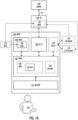
- FIG. 1A illustrates a simplified block diagram of an apparatus 100 for assisting a human operator (or pilot) 120 in flying a drone 160 using a remote controller 150.
- the drone 160 is also known as a UAV (unmanned aerial vehicle).
- a UAS unmanned aircraft system
- a UAS may be defined as including the drone (or UAV) 160, the (ground-based) remote controller 150, and a wireless communications system 152 between the remote controller 150 and the drone 160.
- FIG. 30 which is a flow chart illustrating embodiments of a method for assisting the human operator 120 in flying the drone 160 using the remote controller 150, is referred to.
- the method starts in 3000 and ends in 3010. Note that the method may run as long as required (after the start-up of the apparatus 100 until switching off) by looping back to an operation 3002.
- the operations are not strictly in chronological order in FIG. 30 , and some of the operations may be performed simultaneously or in an order differing from the given ones. Other functions may also be executed between the operations or within the operations and other data exchanged between the operations. Some of the operations or part of the operations may also be left out or replaced by a corresponding operation or part of the operation. It should be noted that no special order of operations is required, except where necessary due to the logical requirements for the processing order.
- the apparatus 100 comprises an internal data communication interface 108 configured to receive 3002 data related to the flying from the remote controller 150.
- the data related to the flying may include telemetry data of the drone 160.
- the data related to the flying may include, but is not limited to: sensor readings such as gyroscope and magnetometer, angular rate, velocity, fusion data such as altitude and global position, aircraft information such as battery, gimbal, and flight status, etc. Note that depending on the drone environment, some data may also be received by the apparatus 100 directly from the drone 160.
- the internal data communication interface 108 may be implemented using a wireless radio transceiver configured to communicate with a wireless transceiver of the remote controller 150.
- the technologies for the internal data communication interface 108 include, but are not limited to one or more of the following: a wireless local area network (WLAN) implemented using an IEEE 802.11ac standard or a Wi-Fi protocol suite, a short-range radio network such as Bluetooth or Bluetooth LE (Low Energy), a cellular radio network employing a subscriber identity module (SIM) or an eSIM (embedded SIM), or another standard or proprietary wireless connectivity means.
- the internal data communication interface 108 may additionally or alternatively utilize a standard or proprietary wired connection such as an applicable bus, for example.
- An embodiment utilizes a wired connection according to the USB (Universal Serial Bus) standard.
- the apparatus 100 also comprises an augmented reality (AR) display 112 configured to display 3004 the data related to the flying to the human operator 120.
- AR augmented reality
- FIG. 2 to FIG. 29 show specific embodiments, but besides these, also various notifications and statuses related to the flying may be shown on the augmented reality display 112.
- the augmented reality display 112 is implemented as a head-mounted display attached with a headband (or being a helmet-mounted) and worn as a visor in front of the eyes by the human operator 120.
- the augmented reality display 112 is implemented as a see through display on which holographic images are displayed.
- the augmented reality display 112 may employ cameras to intercept the real world view and display an augmented view of the real world as a projection.
- the apparatus 100 is implemented using Microsoft ® HoloLens ® 2 (or a later version) mixed reality smartglasses employing see-through holographic lenses as the augmented reality display 112, offering a complete development environment.
- the head-mounted apparatus 100 then includes the necessary processors (including a system on a chip, a custom-made holographic processing unit, and a coprocessor) 102, memories 104 and software 106, a depth camera, a video camera, projection lenses, an inertial measurement unit (including an accelerometer, a gyroscope, and a magnetometer), a wireless connectivity unit 108, 110, and a rechargeable battery. Note that some of these parts are not illustrated in FIG. 1 .
- Such a ready-made environment offers an augmented reality engine 144 configured to provide the basic operations related to fusing the real world and the augmented reality together and tracking head and eye movements of the human operator 120, for example.
- the augmented reality display 112 is configured to provide an interactive real-time experience of a real-world flying environment 210 and the drone 160 enhanced by computer-generated perceptual information.
- the data related to the flying is superimposed (or overlaid) in addition to the natural environment 210 and the drone 160.
- the apparatus 100 also comprises one or more memories 104 including computer program code 106, and one or more processors 102 configured to execute the computer program code 106 to cause the apparatus 100 to perform required data processing.
- the data processing performed by the apparatus 100 may be construed as a method or an algorithm 130.
- the term 'processor' 102 refers to a device that is capable of processing data.
- the processor 102 is implemented as a microprocessor implementing functions of a central processing unit (CPU) on an integrated circuit.
- the CPU is a logic machine executing the computer program code 106.
- the CPU may comprise a set of registers, an arithmetic logic unit (ALU), and a control unit (CU).
- the control unit is controlled by a sequence of the computer program code 106 transferred to the CPU from the (working) memory 104.
- the control unit may contain a number of microinstructions for basic operations.
- the implementation of the microinstructions may vary, depending on the CPU design.
- the one or more processors 102 may be implemented as cores of a single processors and/or as separate processors.
- the working memory and the non-volatile memory may be implemented by a random-access memory (RAM), dynamic RAM (DRAM), static RAM (SRAM), a flash memory, a solid state disk (SSD), PROM (programmable read-only memory), a suitable semiconductor, or any other means of implementing an electrical computer memory.
- the computer program code 106 is implemented by software.
- the software may be written by a suitable programming language, and the resulting executable code may be stored in the memory 104 and executed by the one or more processors 102.
- the computer program code 106 implements the method/algorithm 130.
- the computer program code 102 may be coded as a computer program (or software) using a programming language, which may be a high-level programming language, such as C, C++, or Rust, for example.
- the computer program code 106 may be in source code form, object code form, executable file, or in some intermediate form, but for use in the one or more processors 102 it is in an executable form as an application 140.
- There are many ways to structure the computer program code 106 the operations may be divided into modules, subroutines, methods, classes, objects, applets, macros, etc., depending on the software design methodology and the programming language used.
- software libraries i.e. compilations of ready-made functions, which may be utilized by the computer program code 106 for performing a wide variety of standard operations.
- an operating system (such as a general-purpose operating system) may provide the computer program code 106 with system services.
- An embodiment provides a computer-readable medium 170 storing the computer program code 106, which, when loaded into the one or more processors 102 and executed by one or more processors 102, causes the one or more processors 102 to perform the method/algorithm 130 described in FIG. 30 .
- the computer-readable medium 170 may comprise at least the following: any entity or device capable of carrying the computer program code 106 to the one or more processors 102, a record medium, a computer memory, a read-only memory, an electrical carrier signal, a telecommunications signal, and a software distribution medium. In some jurisdictions, depending on the legislation and the patent practice, the computer-readable medium 170 may not be the telecommunications signal.
- the computer-readable medium 170 may be a computer-readable storage medium.
- the computer-readable medium 170 may be a non-transitory computer-readable storage medium.
- the computer-readable medium 170 may carry the computer program code 160 as the executable application 140 for the apparatus 100, and as an executable application 142 for the remote controller 150 to transmit the data related to the flying to the apparatus 100.
- a software development kit may be used for the application 142 to interface with the remote controller 150.
- FIG. 1A illustrates the apparatus 100 as an integrated unit comprising the augmented reality display 112, the one or more memories 104 including the computer program code 106, and the one or more processors 102.
- the apparatus 100 may also be implemented as a distributed apparatus 100 so that the human operator 120 is provided with the augmented reality display 112, but with a separate processing part 180, which is communicatively coupled with the augmented reality display 112 and the remote controller 150, and which comprises the one or more memories 104 including the computer program code 106, and the one or more processors 102.
- processing part 180 is a user apparatus such as a smartphone, tablet computer or a portable computer carried by the human operator 120, and the communication coupling may be wired or wireless.
- the processing part 180 is a networked computer server, which interoperates with the augmented reality display 112 according to a client-server architecture, a cloud computing architecture, a peer-to-peer system, or another applicable distributed computing architecture.
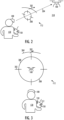
- FIG. 2 and FIG. 3 illustrate embodiments of views offered by the augmented reality display 112 of the apparatus 100. Note that all drawings from FIG. 2 to FIG. 29 illustrate each use case as a combination of two different visual angles.
- a first visual angle illustrates the flying: the human operator 120 operates the remote controller 150 and observes (or looks towards) 204 the drone 160 in the air 210 through the apparatus 100, or, expressed more precise, through the augmented reality display 112 of the apparatus 100.
- a second visual angle illustrates elements 200, 202 shown on the augmented reality display 112.
- a dotted arrow line 204 shows the direction the human operator 120 is looking towards, normally towards the drone 160 in the air, but in some use cases, the human operator 120 is looking towards another direction such as towards the ground, the direction of gaze marked with dotted arrow lines referred to by reference signs 600, 1404, 1706, 1804, 2602.
- the direction of the gaze towards the augmented reality display 112 may differ from the capture direction of the cameras. For example, to ease the flying position, the human operator 120 need not tilt the head to gaze into the sky, but the cameras are tilted upwards.
- the human operator 120 is standing on the ground 500, and the drone 160 is flying in the air 210.
- the embodiments are also applicable to other kind of environments, such as flying the drone 160 in an underground cave, inside a man-made structure (such as a building or a tunnel), or even in such use cases where the drone 160 is flying below the human operator 120, i.e, the human operator 120, while looking 204 towards the drone 160, is looking down and not up.
- the human operator 120 may be standing on a high platform (such as a skyscraper or a mountain), and the drone 160 is flying below (such as above the streets or in a valley).
- the embodiments may also be applied to flying the drone 160 submersed, i.e., the drone 160 is then an unmanned underwater vehicle (UUV), and the human operator 120 may operate the drone 160 from the land or from a vessel, for example, while the drone is underwater in a river, lake, sea, water-filled mine or tunnel, etc.
- UUV unmanned underwater vehicle
- FIG. 2 to FIG. 29 are hybrids illustrating an augmented reality on top of the real world.
- the real world is illustrated from an external view (like a view of another person observing the use case from outside of the real world), whereas the augmented reality display 112 is illustrated from a first person view of the human operator 120.
- the apparatus 100 is caused to superimpose 3006, on the augmented reality display 112, a target symbol 200 indicating a position of the drone 160 (in the air 210 for the UAV) while the human operator 120 is looking 204 towards the drone 160 (in the air 210 for the UAV).
- the apparatus is also caused to superimpose 3008, on the augmented reality display 112, an orientation symbol 202 indicating an orientation of the drone 160 (in the air 210 for the UAV) while the human operator 120 is looking 204 towards the drone 160 (in the air 210 for the UAV).
- the use of the augmented reality display 112 enables the human operator 120 to look 204 towards the drone 160 in the sky 210 during the flying. This improves the situational awareness of the human operator 120 regarding the flying, without needing the spotter.
- the human operator maintains a visual contact (by a line of sight) to the drone 160 in the air 210, but is also simultaneously shown aviation data in actual correct world positions as will be explained.
- the target symbol 200 indicates the position of the drone 160 in the air 210, which makes it easier for the human operator 120 to track the drone 160 during the flying.
- the target symbol 200 is a reticle as illustrated.
- the reticle 200 is commonly used in a telescopic sight of a firearm.
- the reticle 200 may include a combination of a circle 300 and a partial crosshair 302 as shown in FIG. 3 , but also other patterns may be used such as dots, posts, chevrons, etc.
- the orientation symbol 202 indicates the orientation of the drone 160 in the air 210, which makes it easier for the human operator 120 to understand an effect of the steering commands given with the remote controller 150 to the drone 160 during the flying.
- the orientation symbol 202 is an arrow as illustrated. As shown in FIG. 3 , the arrow 202 may be augmented by an arc 304, which illustrates a part of a 360 degrees circle around the human operator 120. The arrow 202 may point a heading of the drone 160 as will later be explained.
- the target symbol 200 and the orientation symbol 202 from the digital world blend into the human operator's 120 perception of the real world, through the integration of immersive sensations, which are perceived as natural parts of the flying environment 210.
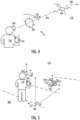
- FIG. 4 illustrates an orientation of the drone 160.
- the orientation symbol 202 is configured to point out a predetermined direction fixed in relation to the orientation of the drone 160 in the air 210.
- the remote controller 150 may include two joysticks 310, 312, for example, to give the steering commands.
- the remote controller 150 may control the drone 160 in various degrees of freedom: a roll, which tilts the drone 160 left or right, a pitch, which tilts the drone 160 forward or backward, and a yaw, which rotates the drone 160 clockwise or counterclockwise.
- an altitude control controls the drone 160 to fly higher or lower.
- some user interface elements of the remote controller 150 may be programmed to interact with the apparatus 100 so that user interface operations of the apparatus 100, besides being performed in the augmented reality environment, may also be performed with (physical) user interface elements of the remote controller 150.
- the predetermined direction is fixed in relation to a heading 400 of the drone 160.
- the heading 400 of the drone 160 is a compass direction in which a nose of the drone 160 is pointed.
- FIG. 5 illustrates the various coordinate systems 502, 504, 506 that need to be related to each other in order to enable the embodiments.
- a world coordinate system 502 defines a three-dimensional world model visualization, which is mapped to a coordinate system 504 of the apparatus 100 and to a coordinate system 506 of the drone 160.
- the apparatus 100 shows the augmented reality using its own coordinate system 504 but also illustrating the position of the drone 160 and the position of the human operator 120 in the world coordinate system 502.
- the apparatus 100 is caused to perform:
- the augmented reality coordinate system 504 that constantly tracks any movement of the head of the human operator 120, is now firmly based in the world coordinates 502, and also follows the actual compass directions 602. The coupling of world latitude and longitude (x and z of the world coordinate system 502) and the compass heading information 602 into the augmented reality presentation is thus achieved.
- the apparatus 100 is caused to perform:
- the augmented reality system is shown the position of the drone 160 in the world coordinate system 502, and the position of the drone 160 in relation to the augmented reality coordinate system 504.
- the drone 160 centre is situated in this exact spot within the augmented reality field of view 112
- augmented reality indicators that spot is now known both in the real world coordinate system 502 and in the augmented reality system coordinates 504.
- a fixed common position with the world latitude and longitude information is obtained. This latitude and longitude comes from the 160 drone, as it knows at this moment its exact coordinates (provided by GPS or another global navigation satellite system, or by another positioning technology such as a cellular radio -based positioning).
- An augmented reality pointer stick or another type of the calibration position symbol may indicate a position in the augmented reality display 112 for the human operator 120.
- this stick which moves at a fixed distance in front of the human operator 160 and points down, is guided to be on top of the centre of the drone 160. It is held steady to confirm the position, which then locks the coordinate systems 502, 504 together.
- this may also be done using a machine vision, just seeing the drone 160 and deciphering its place in the augmented reality coordinate system 504, then locking the drone 160 latitude, longitude and even heading into that shape. Showing the position of the drone 160 may be done in many ways, but it needs to be done with confidence to lock the world and augmented reality coordinate systems 502, 504 reliably together.
- the drone 160 knows where its nose is pointed at, i.e., the drone 160 tells its compass heading in degrees, this may be used to finalize the coupling of the coordinate systems 502, 504.
- the augmented reality system is used to align a displayed line or another type of the calibration orientation symbol with a tail-nose -line of the drone 160, and when this is achieved, this compass orientation of the displayed line in the world coordinate system 502 is now known.
- the world compass heading of any direction for example North may be calculated from it.
- an exact altitude (y in the world coordinate system 502) may also be queried from a map system based on the exact world coordinates 502, or from the drone 160 itself, possibly via the remote controller 150. So, we may also calibrate an altitude for this point in space (with a drone-specific offset of the top surface of the drone 160 from the ground 500, if an exact precision is needed), and so use the map data to accurately determine any other world point terrain altitude from here on. To summarize, the latitude, the longitude, possibly the altitude, and the compass heading may be needed for the world locking to be achieved.
- the data related to the flying is mapped to the world coordinates 502, and is consequently displayed 3004, 3006, 3008 so that its visualization takes advantage of knowing its three-dimensional position expressed in the world coordinate system 502, which is locked to the augmented reality coordinate system 504.
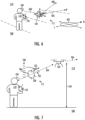
- the situational awareness may further be enhanced with numerical information.
- the apparatus 100 is caused to superimpose, on the augmented reality display 112, a cruising altitude 704 of the drone 160 using a numerical value and a scale 700 visually coupled with the target symbol 200 while the human operator 120 is looking 204 towards the drone 160 in the air 210.
- the scale 700 may include horizontal lines each indicating a specific altitude.
- the apparatus is also caused to superimpose, on the augmented reality display 112, a heading 706 of the drone 160 in degrees 702 visually coupled with the orientation symbol 202 while the human operator 120 is looking 204 towards the drone 160 in the air 210. This may be useful for an expert human operator 120.
- the apparatus 100 is caused to superimpose, on the augmented reality display 112, an indirect line of sight guideline 800 extending horizontally to the geographic location of the drone 160 on the ground 500, from which the indirect line of sight guideline 802 continues to extend vertically to the target symbol 200 in a cruising altitude of the drone 160 in the air 210 while the human operator 120 is looking 204 towards the drone 160 in the air 210.
- This may further enhance the situational awareness, as the human operator 120 may first observe the horizontal guideline 800 to see the geographic location of the drone 160 on the earth surface 500, and then observe the vertical guideline 802 to grasp where the drone 160 is in the air 210.
- the apparatus 100 is caused to superimpose, on the augmented reality display 112, a track symbol 900 indicating a track 902 and a speed of the drone 160 in the air 210 while the human operator 120 is looking 204 towards the drone 160 in the air 210.
- the track 902 is a route that the drone 160 actually travels.
- a difference between the heading 400 and the track 902 is caused by a motion of the air 210 (such as by an air current).
- the human operator 120 foresees an effect of the current control, which may then be adjusted as necessary.
- FIG. 10 illustrates embodiments of visualizing an obstacle in relation to the drone 160.
- the apparatus 100 is caused to superimpose, on the augmented reality display 112, an obstruction indicator symbol 1000 configured to depict a distance 1002 of the drone 160 to a real object 1004 while the human operator 120 is looking 204 towards the drone 160 in the air 210.
- the distance 1002 may be the shortest distance between the drone 160 and the real object 1004.
- the obstruction indicator symbol 1000 may mark the distance using an arrow, possibly augmented by a numerical value indicating the distance 1002.
- the real object 1004 may be a man-made object such as a building, a bridge, etc., or a natural object such as a hill, a forest, etc.
- FIG. 11 illustrates an additional embodiment, wherein the obstruction indicator symbol 1000 comprises a visual indicator 1100 superimposed at least partly over the real object 1004.
- the visual indicator 1100 may be a shading or a similar visual effect overlaid on the real object 1004. In this way, the human operator 120 immediately recognizes a collision danger as the drone 160 approaches the object 1004.
- FIG. 12 illustrates a further embodiment, applicable to either the embodiment of FIG. 10 or the embodiment of FIG. 11 .
- the obstruction indicator symbol 1200 comprises elements depicting a shortest horizontal 1202 and vertical 1204 distance from the drone 160 to the real object 1206. In this way, an effect of both vertical and horizontal movement of the drone 160 may be recognized in order to avoid a collision with the real object 1206.
- FIG. 13 illustrates embodiments of visualizing a waypoint in relation to the drone 160.
- the apparatus 100 is caused to superimpose, on the augmented reality display 112, a map 1300 showing a geographic location 1302 of the human operator 120, a geographic location 1304 of the drone 160, and a waypoint 1306.
- the human operator 120 intuitively has a better understanding of the surroundings related to the flying.
- the map 1300 and the drone 160 may be simultaneously within the field of vision of the human operator 120, and the gaze may alternate as being directed 204 to the drone or being directed 1310 to the map 1300.
- the apparatus 100 is also caused to superimpose, on the augmented reality display 112 a vertical waypoint symbol 1308 starting from a geographic location of the waypoint 1306 on the ground 500 and extending towards a predetermined altitude of the waypoint 1306 while the human operator 120 is looking 204 towards the drone 160 in the air 210.
- a narrow part of the waypoint symbol 1308 may accurately pinpoint the geographic location on the earth 500, whereas a broader part of the waypoint symbol 1308 may indicate the set altitude of the waypoint in the air 210. In this way, the waypoint symbol 1308 is shown in the correct location of the real world.
- FIG. 14 and FIG. 15 illustrate embodiments of visualizing data captured by the drone 160.
- the apparatus 100 is caused to superimpose, on the augmented reality display 112, one or more visual elements 1400 captured in real-time using one or more sensors 1402 onboard the drone 160 in the vicinity of the target symbol 200 while the human operator 120 is looking 204 towards the drone 160 in the air 210, and position, on the augmented reality display 112, the one or more visual elements 1400 so that a line of sight remains unobstructed while the human operator 120 is looking 204 towards the drone 160 in the air 210.
- the visual element(s) 1400 may be placed on either side of the target symbol 200 as shown, but also anywhere around the target symbol 200.
- the human operator 120 may quickly glance 1404 the visual element(s) 1400, but mainly look 204 towards the drone 160 and simultaneously steer the drone 170.
- an image sensor 1402 captures images or a video feed as the data, which is then superimposed as the visual element 1400 on the augmented reality display 112. In this way, the human operator 120 may steer the drone 120 so that the image sensor 1402 shoots the desired view.
- the image sensor may operate as a (normal) visible light camera such as a photographic camera or a video camera. Besides this, the image sensor may operate as a thermal (or infrared) camera, a multispectral camera, a hyperspectral camera, or a corona discharge camera, for example.
- the one or more sensors 1402 onboard the drone 160 may comprise, but are not limited to one or more of the following technologies: a lidar (light detection and ranging, or laser imaging, detection, and ranging, or 3-D laser scanning) sensor, a sonar (sound navigation and ranging) sensor, a radar (radio detection and ranging) sensor, a chemical sensor, a biological sensor, a radiation sensor, a particle sensor, a magnetic sensor, a network signal strength sensor, etc.
- the drone 160 may carry any combination of these sensors 1402 as the payload, whose data is then visualized as explained with the dynamically positioned one or more visual elements 1400.
- FIG. 16 and FIG. 17 illustrate embodiments of visualizing maps related to the flying of the drone 160.
- the human operator 120 may choose the layout of the map 1600, 1700, or the apparatus 100 may automatically decide which layout to use depending on the flying situation.
- the apparatus 100 is caused to superimpose, on the augmented reality display 112, a map 1600 in a vertical layout showing a geographic location 1602 of the human operator 120 and a geographic location 1604 of the drone 160 in the vicinity of the target symbol 200 on the augmented reality display 112 while the human operator 120 is looking 204 towards the drone 160 in the air 210.
- the apparatus 100 is caused to superimpose, on the augmented reality display 112, a map 1700 in a horizontal layout showing a geographic location 1702 of the human operator 112 and a geographic location 1704 of the drone 160 while the human operator 120 is looking 1706 towards the ground 500.
- the vertical layout map 1600 the situational awareness may be retained at all times as the human operator gazes 204 towards the drone 160 and sees the map 1600 at the side.
- the horizontal layout map 1700 the human operator 120 needs to look 1706 towards the ground 500, but as shown the map 1700 may be shown larger and more intuitively as the map 1700 surface is parallel with the earth surface 500.
- FIG. 17 also illustrates that the used maps 1700 may be three-dimensional topographic maps illustrating also the altitude data as depicted by the three-dimensional buildings 1708.
- FIG. 18 and FIG. 19 illustrate embodiments of visualizing menu structures of the apparatus 100.
- the apparatus 100 is caused to superimpose, on the augmented reality display 112, a menu structure 1800 around the human operator 120 while the human operator 120 is looking 1804 towards the ground 500.
- the apparatus 100 is caused to detect a gesture 1802 from the human operator 120 as a command related to the menu structure 1800, and control, on the augmented reality display 112, the display 1900 of the data related to the flying based on the command.
- the human operator 120 may quickly manipulate the apparatus 100.
- the basic display of the target symbol 200 and the orientation symbol 202 are shown
- the human operator 120 has chosen from the menu structure 1800 to display the cruising altitude of the drone 160 using the numerical value and the scale 700 visually coupled with the target symbol 200 as explained earlier with reference to FIG. 7 .
- FIG. 20, FIG. 21 , and FIG. 22 illustrate embodiments of visualizing external data related to a physical environment of the drone 160.
- the apparatus 100 comprises an external data communication interface 110 configured to receive external data 114 related to a physical environment of the drone 160.
- the external data communication interface 110 may in an embodiment be implemented using the internal data communication interface 108.
- the apparatus 100 is caused to superimpose, on the augmented reality display 112, one or more visualizations 2000 of the external data 114.
- the apparatus 100 may increase the situational awareness of the human operator 120 by incorporating external data sources to the single user interface implemented by the augmented reality display 112.
- the external data 114 is mapped to the world coordinates 502, and is consequently displayed so that its visualization takes advantage of knowing its three-dimensional position expressed in the world coordinate system 502, which is locked to the augmented reality coordinate system 504.
- the external data communication interface 110 may also be used to communicate data related to the flying to outside receivers 116, the data being transmitted including, but not being limited to: the position of the drone 160, speech from the human operator 120, one or more video feeds from the drone 160, etc.
- the external data 114 may comprise weather data, and the one or more visualizations 2000 depict the weather data.
- the weather data includes information on a speed and a direction of the wind. The direction may be indicated by arrows, and the speed may be indicated by a scale of the arrows as shown or alternatively by a numerical value.
- the weather data may include one or more of the following: turbulences (predicted or known), humidity, cloud visualizations, rain warnings, hail warnings, snow warnings, storm warnings, warnings about lightning, lighting conditions (time of day, position of sun and/or moon), fog, air temperature and pressure, visibility, dew point (important for aviation pilots), "feels like” temperature. And all this may also be tied to time, i.e., the weather predictions may be visualized, for example incoming cloud fronts and wind changes.
- the external data may comprise 114 air traffic control data including classifications of airspaces, and the one or more visualizations 2100, 2102 depict the classification of the airspace matching the position of the drone 160 in the air 210.
- a free airspace 2100 may be marked with "I”
- a restricted airspace 2102 may be marked with "II” and a shaded rectangle as shown or with another three-dimensional shape (such as a polygon mesh) or even with a two-dimensional shape (such as a polygon).
- the classifications of airspace may include, but are not limited to: drone no fly zones (areas, volumes), reservations and notifications of airspaces for drone and/or other aviation operations, airfield control zones, airspace control zones, power lines and other obstacles, country border zones, all of the aforementioned in different altitudes, warning/danger/restricted zones, UAV reserved areas, UAS reserved areas, model airplane reserved areas.
- An aviation map may be visualized using a three-dimensional polygon mesh with various walls, roofs, flight levels, etc, all of which are in their correct places as seen in the augmented reality display 112.
- the external data may comprise 114 air traffic control data including positions of aircraft 2200 in the air 210, and the one or more visualizations 2202, 2204 depict the positions of the aircraft 2200 in the air 210.
- the one or more visualizations 2202, 2204 are shown for the aircraft 2200 flying within a predetermined distance (such as within a radius of 3, 5 or 10 kilometres, for example) from the position of the drone 160 in the air 210.
- the visualizations may be implemented with arrows 2202, 2204 indicating the location of the aircraft 2200, and additionally or alternatively a simulation of the aircraft 2200 may be shown.
- FIG. 23 , FIG. 24 , FIG. 25 , FIG. 26, and FIG. 27 illustrate embodiments of visualizing a line of sight to the drone 160 during different visibilities.
- the apparatus 100 is caused to superimpose, on the augmented reality display 112, the data related to the flying while the human operator 120 is looking 204 towards the drone 160 in the air 210 with a visual line of sight to the drone 160 during a good visibility. This is the ideal flying situation.
- the apparatus 100 is caused to superimpose, on the augmented reality display 112, the data related to the flying while the human operator 120 is looking 204 towards the drone 160 in the air 210 with an augmented line of sight to the drone 160 during an impaired visibility.
- the augmented line of sight may be achieved by guiding the human operator 120 to look at the right direction with the target symbol 200.
- a simulated drone 160 may be shown in the correct position.
- the impaired visibility may be caused by a low-light condition, cloud, fog, smog, rain, snowfall, or some other physical phenomenon.
- the apparatus 100 is caused to superimpose, on the augmented reality display 112, the data related to the flying while the human operator 120 is looking 204 towards the drone 160 in the air 210 with an augmented and simulated line of sight to the drone 160 during an obstructed visibility.
- the obstructed visibility may be caused by an obstacle 2502, i.e., the drone 160 is behind the obstacle 2502.
- the obstacle 2502 may be the real object 1004 of FIG. 10 and FIG. 11 , i.e, the obstacle 2502 may be a man-made object such as a building, a bridge, etc., or a natural object such as a hill, a forest, etc.
- the augmentation is achieved by guiding the human operator 120 to look at the right direction with the target symbol 200, and the simulation by showing a simulated drone 160 in the correct position.
- the apparatus 100 is caused to superimpose, on the augmented reality display 112, the data related to the flying while the human operator 120 is looking 204 towards the drone 160 in the air 210 with an augmented line of sight to the drone 160 during a long-distance visibility.
- This is not shown in any drawing, but basically the drone 160 is then high up in the sky, or near the horizon, for example, and the human operator 120 is guided to look at the right direction with the target symbol 200, whereby the human operator 120 may only see the drone 160 as a tiny object in the distance.
- the apparatus 100 is caused to adjust 2700, on the augmented reality display 112, the display 2600 of the data related to the flying so that a line of sight 2602 remains unobstructed while the human operator 120 is looking 204 towards the drone 160 in the air 210.
- the human operator 120 keeps on looking 204 towards the drone 160 with a free line of sight 2602.
- the map 2600 would eventually obstruct the line of sight 2602.
- the drone 160 is now flying relatively low, but the line of sight 2602 remains free due to the moving 2700 of the map 2600 to the left.
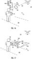
- FIG. 28 and FIG. 29 illustrate embodiments of a system comprising two apparatuses 100, 2800.
- a first apparatus 100 is used for assisting a first human operator 120 in flying the drone 160 in the air using 210 the remote controller 150.
- a first geographic location 2814 of the first human operator 120 in relation to the position of the drone 160 in the air 210 is used to adjust a first viewpoint for rendering the data related to the flying including a first target symbol 200 and a first orientation symbol 202 to be superimposed on a first augmented reality display 112 of the first apparatus 100.
- a second apparatus 2800 is used for informing a second human operator 2802 in relation to flying the drone 160 in the air 210.
- a second geographic location 2804 of the second human operator 2802 in relation to the position of the drone 160 in the air 210 is used to adjust a second viewpoint for rendering the data related to the flying including a second target symbol 2806 and a second orientation symbol 2808 to be superimposed on a second augmented reality display 2810 of the second apparatus 2800.
- the second human operator 2802 may at least observe 2812 the flying of the drone 160 in the air 210. This may be useful just for fun, for educational purposes, for passing a test for a flying license, for surveillance, for tracking a missing person, or even for assisting the first human operator 120, for example.
- One or both operators 120, 2802 may also be provided with the one or more visual elements based on the data captured in real-time using the one or more sensors 1402 onboard the drone 160 as explained earlier.
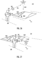
- the second apparatus 2800 is used for assisting the second human operator 2802 in relation to controlling 2902 one or more sensors 1402 onboard the drone 160, while the first human operator 120 controls the flying direction 2908 and speed of the drone 160.
- the second geographic location 2804 of the second human operator 2802 is used to adjust the second viewpoint for rendering the data related to the flying including also the one or more video feeds captured in real-time from the one or more video cameras 2900 onboard the drone 160 to be superimposed on the second augmented reality display 2810 of the second apparatus 2800. As shown in FIG. 29 , the one or more video feeds 2904 are superimposed on the second augmented reality display 2810.
- FIG. 29 may also be such that both operators 120, 2802 may be shown the same information on the augmented reality displays 112, 2810, and as they both have remote controllers 150, 2906, the responsibility for the flying may be seamlessly transferred on the fly between the operators 120, 2906. This may be especially useful during a training session or during a long mission. It is also envisaged, that in an especially hazardous or restricted airspace, an authorized pilot 2802 may pilot the drone 160 safely across, and thereafter the (original) operator 120 regains the control of the drone 160.
- the scenarios of FIG. 28 and FIG. 29 are not limited to the second human operator 2802 being physically present near the drone 160 and the first human operator 120.
- the external data communication interface 110 may communicate data related to the flying to the outside receiver 116.
- the outside receiver 116 may be a networked computer server, which interoperates with the first apparatus 100 and the second apparatus 2800 according to a client-server architecture, a cloud computing architecture, a peer-to-peer system, or another applicable distributed computing architecture.
- the second human operator 120 may be far away, even in a different city, country, or continent, and still able to observe or even assist as described.
- data transmission delays need to be minimized and taken into account, especially if the remote second human operator 2802 is controlling 2902 the one or more sensors 1402, for example.
Description
- Various embodiments relate to an apparatus for assisting a human operator in flying a drone using a remote controller, a method for assisting the human operator in flying the drone using the remote controller, and a computer-readable medium comprising computer program code, which, when executed by one or more processors, causes performance of the method.
- A (ground-based) human operator flies a drone (or an unmanned aerial vehicle, UAV) using a remote controller (sometimes at least partly assisted by an autopilot).
- The human operator has to simultaneously look towards the drone in the air, operate the hand-held remote controller, and occasionally look towards a display of the remote controller. This leads to poor situational awareness, causing potentially hazardous situations.
- A legal requirement is that the human operator must maintain a visual contact (by a line of sight) to the drone in the air. This is quite challenging as the drone may not be visible due to a long distance, low ambient light, or a physical obstacle, for example.
- These problems may be mitigated by another person, a so-called spotter, retaining the visual contact to the drone, even using binoculars, whereas the human operator may concentrate on operating the remote controller (but may still need to check occasionally the display of the remote controller). Naturally, such a setup requires good communication skills for the human operator and the spotter. Additionally, the manual labour is doubled, leading to higher operation costs for the drone.
-
US2018196425A1 discloses a head-mounted display device including an image display, a control section configured to control the image display section, a position detecting section, a visual-field detecting section configured to detect a visual field of the user, and a wireless communication section configured to perform wireless communication with an external apparatus. The control section includes a state-information acquiring section configured to acquire, via the wireless communication section, state information including a position of an own aircraft, which is a mobile body set as an operation target object of the user, and a support-information creating section configured to create, on the basis of a relation between the position and the visual field of the user and the position of the own aircraft, a support image including support information for operation of the own aircraft and cause the image display section to display the support image as the virtual image. -
US2019077504A1 discloses an apparatus for augmented reality travel route planning. An apparatus such as a head-mounted display (HMD) may have a camera for capturing a visual scene for presentation via the HMD. A user of the apparatus may specify a pre-planned travel route for a vehicle within the visual scene via an augmented reality (AR) experience generated by the HMD. The pre-planned travel route may be overlaid on the visual scene in the AR experience so that the user can account for real-time environmental conditions determined through the AR experience. The pre-planned travel route may be transferred to the vehicle and used as autonomous travel instructions. -
US2019049949A1 discloses a modified-reality device including: a head-mounted device including one or more displays, wherein the one or more displays are configured to receive image data representing at least an image element and to display a modified-reality image including at least the image element; one or more sensors configured to provide head tracking data associated with a location and an orientation of the head-mounted device; and a processing arrangement configured to receive flight data associated with a flight of an unmanned aerial vehicle, generate the image data representing at least the image element based on the head tracking data and the flight data, and provide the image data to the one or more displays. - According to an aspect, subject matter of independent claims is provided. Dependent claims define some embodiments.
- One or more examples of implementations are set forth in more detail in the accompanying drawings and the description of embodiments.
- Some embodiments will now be described with reference to the accompanying drawings, in which
-
FIG. 1A andFIG. 1B illustrate embodiments of an apparatus for assisting a human operator in flying a drone using a remote controller; -
FIG. 2 and FIG. 3 illustrate embodiments of views offered by an augmented reality display of the apparatus; -
FIG. 4, FIG. 5 ,FIG. 6, FIG. 7 ,FIG. 8, and FIG. 9 illustrate embodiments of an orientation of the drone; -
FIG. 10, FIG. 11 , andFIG. 12 illustrate embodiments of visualizing an obstacle in relation to the drone; -
FIG. 13 illustrates embodiments of visualizing a waypoint in relation to the drone; -
FIG. 14 and FIG. 15 illustrate embodiments of visualizing data captured by the drone; -
FIG. 16 and FIG. 17 illustrate embodiments of visualizing maps related to the flying of the drone; -
FIG. 18 and FIG. 19 illustrate embodiments of visualizing menu structures of the apparatus; -
FIG. 20, FIG. 21 , andFIG. 22 illustrate embodiments of visualizing external data related to a physical environment of the drone; -
FIG. 23 ,FIG. 24 ,FIG. 25 ,FIG. 26, and FIG. 27 illustrate embodiments of visualizing a line of sight to the drone during different visibilities; -
FIG. 28 and FIG. 29 illustrate embodiments of a system comprising two apparatuses; and -
FIG. 30 is a flow chart illustrating embodiments of a method for assisting the human operator in flying the drone using the remote controller. - The following embodiments are only examples. Although the specification may refer to "an" embodiment in several locations, this does not necessarily mean that each such reference is to the same embodiment(s), or that the feature only applies to a single embodiment. Single features of different embodiments may also be combined to provide other embodiments. Furthermore, words "comprising" and "including" should be understood as not limiting the described embodiments to consist of only those features that have been mentioned and such embodiments may contain also features/structures that have not been specifically mentioned.
- Reference numbers, both in the description of the embodiments and in the claims, serve to illustrate the embodiments with reference to the drawings, without limiting it to these examples only.
- The embodiments and features, if any, disclosed in the following description that do not fall under the scope of the independent claims are to be interpreted as examples useful for understanding various embodiments of the invention.
- Let us study
FIG. 1A , which illustrates a simplified block diagram of anapparatus 100 for assisting a human operator (or pilot) 120 in flying adrone 160 using aremote controller 150. Thedrone 160 is also known as a UAV (unmanned aerial vehicle). A UAS (unmanned aircraft system) may be defined as including the drone (or UAV) 160, the (ground-based)remote controller 150, and awireless communications system 152 between theremote controller 150 and thedrone 160. - Simultaneously,
FIG. 30 , which is a flow chart illustrating embodiments of a method for assisting thehuman operator 120 in flying thedrone 160 using theremote controller 150, is referred to. - The method starts in 3000 and ends in 3010. Note that the method may run as long as required (after the start-up of the
apparatus 100 until switching off) by looping back to anoperation 3002. - The operations are not strictly in chronological order in
FIG. 30 , and some of the operations may be performed simultaneously or in an order differing from the given ones. Other functions may also be executed between the operations or within the operations and other data exchanged between the operations. Some of the operations or part of the operations may also be left out or replaced by a corresponding operation or part of the operation. It should be noted that no special order of operations is required, except where necessary due to the logical requirements for the processing order. - The
apparatus 100 comprises an internaldata communication interface 108 configured to receive 3002 data related to the flying from theremote controller 150. The data related to the flying may include telemetry data of thedrone 160. The data related to the flying may include, but is not limited to: sensor readings such as gyroscope and magnetometer, angular rate, velocity, fusion data such as altitude and global position, aircraft information such as battery, gimbal, and flight status, etc. Note that depending on the drone environment, some data may also be received by theapparatus 100 directly from thedrone 160. - The internal
data communication interface 108 may be implemented using a wireless radio transceiver configured to communicate with a wireless transceiver of theremote controller 150. The technologies for the internaldata communication interface 108 include, but are not limited to one or more of the following: a wireless local area network (WLAN) implemented using an IEEE 802.11ac standard or a Wi-Fi protocol suite, a short-range radio network such as Bluetooth or Bluetooth LE (Low Energy), a cellular radio network employing a subscriber identity module (SIM) or an eSIM (embedded SIM), or another standard or proprietary wireless connectivity means. Note that in some use cases, the internaldata communication interface 108 may additionally or alternatively utilize a standard or proprietary wired connection such as an applicable bus, for example. An embodiment utilizes a wired connection according to the USB (Universal Serial Bus) standard. - The
apparatus 100 also comprises an augmented reality (AR)display 112 configured to display 3004 the data related to the flying to thehuman operator 120. Note that the drawings fromFIG. 2 to FIG. 29 show specific embodiments, but besides these, also various notifications and statuses related to the flying may be shown on theaugmented reality display 112. - In the drawings, the
augmented reality display 112 is implemented as a head-mounted display attached with a headband (or being a helmet-mounted) and worn as a visor in front of the eyes by thehuman operator 120. In the drawings, theaugmented reality display 112 is implemented as a see through display on which holographic images are displayed. In an alternative embodiment, theaugmented reality display 112 may employ cameras to intercept the real world view and display an augmented view of the real world as a projection. - In an embodiment, the
apparatus 100 is implemented using Microsoft® HoloLens® 2 (or a later version) mixed reality smartglasses employing see-through holographic lenses as theaugmented reality display 112, offering a complete development environment. The head-mountedapparatus 100 then includes the necessary processors (including a system on a chip, a custom-made holographic processing unit, and a coprocessor) 102,memories 104 andsoftware 106, a depth camera, a video camera, projection lenses, an inertial measurement unit (including an accelerometer, a gyroscope, and a magnetometer), awireless connectivity unit FIG. 1 . Such a ready-made environment offers anaugmented reality engine 144 configured to provide the basic operations related to fusing the real world and the augmented reality together and tracking head and eye movements of thehuman operator 120, for example. - However, also other applicable implementations of the
augmented reality display 112 may be used, including, but not limited to: eyeglasses, a head-up display, contact lenses with an augmented reality imaging, etc. For the purposes of the present embodiments, theaugmented reality display 112 is configured to provide an interactive real-time experience of a real-world flying environment 210 and thedrone 160 enhanced by computer-generated perceptual information. The data related to the flying is superimposed (or overlaid) in addition to thenatural environment 210 and thedrone 160. - The
apparatus 100 also comprises one ormore memories 104 includingcomputer program code 106, and one ormore processors 102 configured to execute thecomputer program code 106 to cause theapparatus 100 to perform required data processing. The data processing performed by theapparatus 100 may be construed as a method or analgorithm 130. - The term 'processor' 102 refers to a device that is capable of processing data. In an embodiment, the
processor 102 is implemented as a microprocessor implementing functions of a central processing unit (CPU) on an integrated circuit. The CPU is a logic machine executing thecomputer program code 106. The CPU may comprise a set of registers, an arithmetic logic unit (ALU), and a control unit (CU). The control unit is controlled by a sequence of thecomputer program code 106 transferred to the CPU from the (working)memory 104. The control unit may contain a number of microinstructions for basic operations. The implementation of the microinstructions may vary, depending on the CPU design. The one ormore processors 102 may be implemented as cores of a single processors and/or as separate processors. - The term 'memory' 104 refers to a device that is capable of storing data run-time (= working memory) or permanently (= non-volatile memory). The working memory and the non-volatile memory may be implemented by a random-access memory (RAM), dynamic RAM (DRAM), static RAM (SRAM), a flash memory, a solid state disk (SSD), PROM (programmable read-only memory), a suitable semiconductor, or any other means of implementing an electrical computer memory.
- The
computer program code 106 is implemented by software. In an embodiment, the software may be written by a suitable programming language, and the resulting executable code may be stored in thememory 104 and executed by the one ormore processors 102. - The
computer program code 106 implements the method/algorithm 130. Thecomputer program code 102 may be coded as a computer program (or software) using a programming language, which may be a high-level programming language, such as C, C++, or Rust, for example. Thecomputer program code 106 may be in source code form, object code form, executable file, or in some intermediate form, but for use in the one ormore processors 102 it is in an executable form as anapplication 140. There are many ways to structure the computer program code 106: the operations may be divided into modules, subroutines, methods, classes, objects, applets, macros, etc., depending on the software design methodology and the programming language used. In modern programming environments, there are software libraries, i.e. compilations of ready-made functions, which may be utilized by thecomputer program code 106 for performing a wide variety of standard operations. In addition, an operating system (such as a general-purpose operating system) may provide thecomputer program code 106 with system services. - An embodiment provides a computer-
readable medium 170 storing thecomputer program code 106, which, when loaded into the one ormore processors 102 and executed by one ormore processors 102, causes the one ormore processors 102 to perform the method/algorithm 130 described inFIG. 30 . The computer-readable medium 170 may comprise at least the following: any entity or device capable of carrying thecomputer program code 106 to the one ormore processors 102, a record medium, a computer memory, a read-only memory, an electrical carrier signal, a telecommunications signal, and a software distribution medium. In some jurisdictions, depending on the legislation and the patent practice, the computer-readable medium 170 may not be the telecommunications signal. In an embodiment, the computer-readable medium 170 may be a computer-readable storage medium. In an embodiment, the computer-readable medium 170 may be a non-transitory computer-readable storage medium. - As shown in
FIG. 1A andFIG. 1B , the computer-readable medium 170 may carry thecomputer program code 160 as theexecutable application 140 for theapparatus 100, and as anexecutable application 142 for theremote controller 150 to transmit the data related to the flying to theapparatus 100. In a typical drone environment, such as DJI®, a software development kit may be used for theapplication 142 to interface with theremote controller 150. -
FIG. 1A illustrates theapparatus 100 as an integrated unit comprising theaugmented reality display 112, the one ormore memories 104 including thecomputer program code 106, and the one ormore processors 102. - However, as illustrated in
FIG. 1B , theapparatus 100 may also be implemented as a distributedapparatus 100 so that thehuman operator 120 is provided with theaugmented reality display 112, but with aseparate processing part 180, which is communicatively coupled with theaugmented reality display 112 and theremote controller 150, and which comprises the one ormore memories 104 including thecomputer program code 106, and the one ormore processors 102. This may be implemented so that processingpart 180 is a user apparatus such as a smartphone, tablet computer or a portable computer carried by thehuman operator 120, and the communication coupling may be wired or wireless. Another implementation is such that theprocessing part 180 is a networked computer server, which interoperates with theaugmented reality display 112 according to a client-server architecture, a cloud computing architecture, a peer-to-peer system, or another applicable distributed computing architecture. -
FIG. 2 and FIG. 3 illustrate embodiments of views offered by theaugmented reality display 112 of theapparatus 100. Note that all drawings fromFIG. 2 to FIG. 29 illustrate each use case as a combination of two different visual angles. - Let us examine
FIG. 2 and FIG. 3 in more detail. As shown, a first visual angle illustrates the flying: thehuman operator 120 operates theremote controller 150 and observes (or looks towards) 204 thedrone 160 in theair 210 through theapparatus 100, or, expressed more precise, through theaugmented reality display 112 of theapparatus 100. As, shown, a second visual angle illustrateselements augmented reality display 112. - This convention is used in all drawings from
FIG. 2 to FIG. 29 : adotted arrow line 204 shows the direction thehuman operator 120 is looking towards, normally towards thedrone 160 in the air, but in some use cases, thehuman operator 120 is looking towards another direction such as towards the ground, the direction of gaze marked with dotted arrow lines referred to byreference signs augmented reality display 112 may differ from the capture direction of the cameras. For example, to ease the flying position, thehuman operator 120 need not tilt the head to gaze into the sky, but the cameras are tilted upwards. - Note that in all described embodiments, the
human operator 120 is standing on theground 500, and thedrone 160 is flying in theair 210. However, the embodiments are also applicable to other kind of environments, such as flying thedrone 160 in an underground cave, inside a man-made structure (such as a building or a tunnel), or even in such use cases where thedrone 160 is flying below thehuman operator 120, i.e, thehuman operator 120, while looking 204 towards thedrone 160, is looking down and not up. In such a use case, thehuman operator 120 may be standing on a high platform (such as a skyscraper or a mountain), and thedrone 160 is flying below (such as above the streets or in a valley). The embodiments may also be applied to flying thedrone 160 submersed, i.e., thedrone 160 is then an unmanned underwater vehicle (UUV), and thehuman operator 120 may operate thedrone 160 from the land or from a vessel, for example, while the drone is underwater in a river, lake, sea, water-filled mine or tunnel, etc. - In a way, all drawings from
FIG. 2 to FIG. 29 are hybrids illustrating an augmented reality on top of the real world. The real world is illustrated from an external view (like a view of another person observing the use case from outside of the real world), whereas theaugmented reality display 112 is illustrated from a first person view of thehuman operator 120. - Let us now return to
FIG. 2 and FIG. 3 . In an embodiment, theapparatus 100 is caused to superimpose 3006, on theaugmented reality display 112, atarget symbol 200 indicating a position of the drone 160 (in theair 210 for the UAV) while thehuman operator 120 is looking 204 towards the drone 160 (in theair 210 for the UAV). In an embodiment, the apparatus is also caused to superimpose 3008, on theaugmented reality display 112, anorientation symbol 202 indicating an orientation of the drone 160 (in theair 210 for the UAV) while thehuman operator 120 is looking 204 towards the drone 160 (in theair 210 for the UAV). - The use of the
augmented reality display 112 enables thehuman operator 120 to look 204 towards thedrone 160 in thesky 210 during the flying. This improves the situational awareness of thehuman operator 120 regarding the flying, without needing the spotter. The human operator maintains a visual contact (by a line of sight) to thedrone 160 in theair 210, but is also simultaneously shown aviation data in actual correct world positions as will be explained. - The
target symbol 200 indicates the position of thedrone 160 in theair 210, which makes it easier for thehuman operator 120 to track thedrone 160 during the flying. In an embodiment, thetarget symbol 200 is a reticle as illustrated. Thereticle 200 is commonly used in a telescopic sight of a firearm. Thereticle 200 may include a combination of acircle 300 and apartial crosshair 302 as shown inFIG. 3 , but also other patterns may be used such as dots, posts, chevrons, etc. - The
orientation symbol 202 indicates the orientation of thedrone 160 in theair 210, which makes it easier for thehuman operator 120 to understand an effect of the steering commands given with theremote controller 150 to thedrone 160 during the flying. In an embodiment, theorientation symbol 202 is an arrow as illustrated. As shown inFIG. 3 , thearrow 202 may be augmented by anarc 304, which illustrates a part of a 360 degrees circle around thehuman operator 120. Thearrow 202 may point a heading of thedrone 160 as will later be explained. - In the
augmented reality display 112, thetarget symbol 200 and theorientation symbol 202 from the digital world blend into the human operator's 120 perception of the real world, through the integration of immersive sensations, which are perceived as natural parts of the flyingenvironment 210. - Let us next study
FIG. 4, FIG. 5 ,FIG. 6, FIG. 7 ,FIG. 8, and FIG. 9 , which illustrate embodiments of an orientation of thedrone 160. - In an embodiment, the
orientation symbol 202 is configured to point out a predetermined direction fixed in relation to the orientation of thedrone 160 in theair 210. As thehuman operator 120 is aware of the predetermined direction, it is easy to for thehuman operator 120 to understand the way the steering commands given with theremote controller 150 influence the flying. As shown inFIG. 3 , theremote controller 150 may include twojoysticks remote controller 150 may control thedrone 160 in various degrees of freedom: a roll, which tilts thedrone 160 left or right, a pitch, which tilts thedrone 160 forward or backward, and a yaw, which rotates thedrone 160 clockwise or counterclockwise. Furthermore, an altitude control controls thedrone 160 to fly higher or lower. Note that some user interface elements of theremote controller 150 may be programmed to interact with theapparatus 100 so that user interface operations of theapparatus 100, besides being performed in the augmented reality environment, may also be performed with (physical) user interface elements of theremote controller 150. - In an embodiment illustrated in
FIG. 4 , the predetermined direction is fixed in relation to a heading 400 of thedrone 160. In navigation, the heading 400 of thedrone 160 is a compass direction in which a nose of thedrone 160 is pointed. Note that thedrone 160, being a quadcopter (= a helicopter with four rotors), for example, may not have a "natural" nose, in which case one direction of thedrone 160 is just defined as the nose. -
FIG. 5 illustrates the various coordinatesystems system 504 of theapparatus 100 and to a coordinatesystem 506 of thedrone 160. Theapparatus 100 then shows the augmented reality using its own coordinatesystem 504 but also illustrating the position of thedrone 160 and the position of thehuman operator 120 in the world coordinate system 502. - In an embodiment illustrated in
FIG. 5 andFIG. 6 , theapparatus 100 is caused to perform: - obtaining a position of the
drone 160 on theground 500 in the world coordinate system 502; - obtaining a position of the
drone 160 on theground 500 in the augmented reality coordinatesystem 504 of theapparatus 100; - locking the position of the
drone 160 in the augmented reality coordinatesystem 504 with the position of thedrone 160 in the world coordinate system 502; - obtaining the heading 400 of the
drone 160 on theground 500; and - setting the heading 400 as an orientation of a calibration heading symbol in the augmented reality coordinate
system 504 of theapparatus 100. - In this way, the augmented reality coordinate
system 504 that constantly tracks any movement of the head of thehuman operator 120, is now firmly based in the world coordinates 502, and also follows theactual compass directions 602. The coupling of world latitude and longitude (x and z of the world coordinate system 502) and thecompass heading information 602 into the augmented reality presentation is thus achieved. - In a more specific embodiment, the
apparatus 100 is caused to perform: - obtaining (from the
remote controller 150 or from the drone 160), the position of thedrone 160 on theground 500 in the world coordinate system 502; - superimposing, on the
augmented reality display 112, a calibration position symbol; - receiving a first user acknowledgment after the calibration position symbol is placed on the drone 160 (such as on a centre of the
drone 160 or on another predetermined point on the drone 160); - obtaining (from the augmented reality engine 144), the position of the
drone 160 on theground 500 in the augmented reality coordinatesystem 504 of theapparatus 100; - locking the position of the
drone 160 in the augmented reality coordinatesystem 504 with the position of thedrone 160 in the world coordinate system 502; - obtaining (from the
remote controller 150 or from the drone 160), the heading 400 of thedrone 160 on theground 500; - superimposing, on the
augmented reality display 112, a calibration orientation symbol; - receiving a second user acknowledgment after the calibration orientation symbol is aligned with the drone 160 (such as with a tail-nose line of the
drone 160 or with another predetermined orientation of the drone 160); and - setting the heading 400 as the orientation of the calibration orientation symbol in the augmented reality coordinate
system 504 of theapparatus 100. - At first, the augmented reality system is shown the position of the
drone 160 in the world coordinate system 502, and the position of thedrone 160 in relation to the augmented reality coordinatesystem 504. By indicating that thedrone 160 centre is situated in this exact spot within the augmented reality field ofview 112, with augmented reality indicators, that spot is now known both in the real world coordinate system 502 and in the augmented reality system coordinates 504. With this combination, a fixed common position with the world latitude and longitude information is obtained. This latitude and longitude comes from the 160 drone, as it knows at this moment its exact coordinates (provided by GPS or another global navigation satellite system, or by another positioning technology such as a cellular radio -based positioning). An augmented reality pointer stick or another type of the calibration position symbol may indicate a position in theaugmented reality display 112 for thehuman operator 120. When showing thedrone 160 location, this stick, which moves at a fixed distance in front of thehuman operator 160 and points down, is guided to be on top of the centre of thedrone 160. It is held steady to confirm the position, which then locks the coordinatesystems 502, 504 together. Alternatively, this may also be done using a machine vision, just seeing thedrone 160 and deciphering its place in the augmented reality coordinatesystem 504, then locking thedrone 160 latitude, longitude and even heading into that shape. Showing the position of thedrone 160 may be done in many ways, but it needs to be done with confidence to lock the world and augmented reality coordinatesystems 502, 504 reliably together. - Secondly, as the
drone 160 knows where its nose is pointed at, i.e., thedrone 160 tells its compass heading in degrees, this may be used to finalize the coupling of the coordinatesystems 502, 504. The augmented reality system is used to align a displayed line or another type of the calibration orientation symbol with a tail-nose -line of thedrone 160, and when this is achieved, this compass orientation of the displayed line in the world coordinate system 502 is now known. Thus, the world compass heading of any direction, for example North may be calculated from it. - As an optional step, at the time when the world position (latitude, longitude) is obtained from the
drone 160, an exact altitude (y in the world coordinate system 502) may also be queried from a map system based on the exact world coordinates 502, or from thedrone 160 itself, possibly via theremote controller 150. So, we may also calibrate an altitude for this point in space (with a drone-specific offset of the top surface of thedrone 160 from theground 500, if an exact precision is needed), and so use the map data to accurately determine any other world point terrain altitude from here on. To summarize, the latitude, the longitude, possibly the altitude, and the compass heading may be needed for the world locking to be achieved. - After this coupling, everything else in the whole system is built around the knowledge of where the
drone 160 actually is in the world coordinates 502 and what is around it exactly there in the world. Note that the described embodiments related to the coupling may operate as stand-alone embodiments, irrespective of all other embodiments, also those described in relation to the independent claims and other dependent claims. - The data related to the flying is mapped to the world coordinates 502, and is consequently displayed 3004, 3006, 3008 so that its visualization takes advantage of knowing its three-dimensional position expressed in the world coordinate system 502, which is locked to the augmented reality coordinate
system 504. - In an embodiment, illustrated in
FIG. 7 , the situational awareness may further be enhanced with numerical information. Theapparatus 100 is caused to superimpose, on theaugmented reality display 112, acruising altitude 704 of thedrone 160 using a numerical value and ascale 700 visually coupled with thetarget symbol 200 while thehuman operator 120 is looking 204 towards thedrone 160 in theair 210. As shown inFIG. 7 , thescale 700 may include horizontal lines each indicating a specific altitude. The apparatus is also caused to superimpose, on theaugmented reality display 112, a heading 706 of thedrone 160 indegrees 702 visually coupled with theorientation symbol 202 while thehuman operator 120 is looking 204 towards thedrone 160 in theair 210. This may be useful for an experthuman operator 120. - In an embodiment illustrated in
FIG. 8 , theapparatus 100 is caused to superimpose, on theaugmented reality display 112, an indirect line ofsight guideline 800 extending horizontally to the geographic location of thedrone 160 on theground 500, from which the indirect line ofsight guideline 802 continues to extend vertically to thetarget symbol 200 in a cruising altitude of thedrone 160 in theair 210 while thehuman operator 120 is looking 204 towards thedrone 160 in theair 210. This may further enhance the situational awareness, as thehuman operator 120 may first observe thehorizontal guideline 800 to see the geographic location of thedrone 160 on theearth surface 500, and then observe thevertical guideline 802 to grasp where thedrone 160 is in theair 210. - In an embodiment illustrated in
FIG. 9 , theapparatus 100 is caused to superimpose, on theaugmented reality display 112, atrack symbol 900 indicating atrack 902 and a speed of thedrone 160 in theair 210 while thehuman operator 120 is looking 204 towards thedrone 160 in theair 210. In navigation, thetrack 902 is a route that thedrone 160 actually travels. A difference between the heading 400 and thetrack 902 is caused by a motion of the air 210 (such as by an air current). By showing thetrack 902 and the speed, thehuman operator 120 foresees an effect of the current control, which may then be adjusted as necessary. - Let us next study
FIG. 10, FIG. 11 , andFIG. 12 , which illustrate embodiments of visualizing an obstacle in relation to thedrone 160. - In an embodiment illustrated in
FIG. 10 , theapparatus 100 is caused to superimpose, on theaugmented reality display 112, anobstruction indicator symbol 1000 configured to depict adistance 1002 of thedrone 160 to areal object 1004 while thehuman operator 120 is looking 204 towards thedrone 160 in theair 210. Thedistance 1002 may be the shortest distance between thedrone 160 and thereal object 1004. As shown inFIG. 10 , theobstruction indicator symbol 1000 may mark the distance using an arrow, possibly augmented by a numerical value indicating thedistance 1002. Thereal object 1004 may be a man-made object such as a building, a bridge, etc., or a natural object such as a hill, a forest, etc. -
FIG. 11 illustrates an additional embodiment, wherein theobstruction indicator symbol 1000 comprises avisual indicator 1100 superimposed at least partly over thereal object 1004. As shown inFIG. 11 , thevisual indicator 1100 may be a shading or a similar visual effect overlaid on thereal object 1004. In this way, thehuman operator 120 immediately recognizes a collision danger as thedrone 160 approaches theobject 1004. -
FIG. 12 illustrates a further embodiment, applicable to either the embodiment ofFIG. 10 or the embodiment ofFIG. 11 . Theobstruction indicator symbol 1200 comprises elements depicting a shortest horizontal 1202 and vertical 1204 distance from thedrone 160 to thereal object 1206. In this way, an effect of both vertical and horizontal movement of thedrone 160 may be recognized in order to avoid a collision with thereal object 1206. - Let us next study
FIG. 13 , which illustrates embodiments of visualizing a waypoint in relation to thedrone 160. Theapparatus 100 is caused to superimpose, on theaugmented reality display 112, amap 1300 showing ageographic location 1302 of thehuman operator 120, a geographic location 1304 of thedrone 160, and awaypoint 1306. In this way, thehuman operator 120 intuitively has a better understanding of the surroundings related to the flying. As shown inFIG. 13 , themap 1300 and thedrone 160 may be simultaneously within the field of vision of thehuman operator 120, and the gaze may alternate as being directed 204 to the drone or being directed 1310 to themap 1300. Theapparatus 100 is also caused to superimpose, on the augmented reality display 112 avertical waypoint symbol 1308 starting from a geographic location of thewaypoint 1306 on theground 500 and extending towards a predetermined altitude of thewaypoint 1306 while thehuman operator 120 is looking 204 towards thedrone 160 in theair 210. A narrow part of thewaypoint symbol 1308 may accurately pinpoint the geographic location on theearth 500, whereas a broader part of thewaypoint symbol 1308 may indicate the set altitude of the waypoint in theair 210. In this way, thewaypoint symbol 1308 is shown in the correct location of the real world. - Next,
FIG. 14 and FIG. 15 illustrate embodiments of visualizing data captured by thedrone 160. Theapparatus 100 is caused to superimpose, on theaugmented reality display 112, one or morevisual elements 1400 captured in real-time using one ormore sensors 1402 onboard thedrone 160 in the vicinity of thetarget symbol 200 while thehuman operator 120 is looking 204 towards thedrone 160 in theair 210, and position, on theaugmented reality display 112, the one or morevisual elements 1400 so that a line of sight remains unobstructed while thehuman operator 120 is looking 204 towards thedrone 160 in theair 210. The visual element(s) 1400 may be placed on either side of thetarget symbol 200 as shown, but also anywhere around thetarget symbol 200. In any case, thehuman operator 120 may quicklyglance 1404 the visual element(s) 1400, but mainly look 204 towards thedrone 160 and simultaneously steer thedrone 170. In the illustrated embodiment, animage sensor 1402 captures images or a video feed as the data, which is then superimposed as thevisual element 1400 on theaugmented reality display 112. In this way, thehuman operator 120 may steer thedrone 120 so that theimage sensor 1402 shoots the desired view. Note that the image sensor may operate as a (normal) visible light camera such as a photographic camera or a video camera. Besides this, the image sensor may operate as a thermal (or infrared) camera, a multispectral camera, a hyperspectral camera, or a corona discharge camera, for example. The one ormore sensors 1402 onboard thedrone 160 may comprise, but are not limited to one or more of the following technologies: a lidar (light detection and ranging, or laser imaging, detection, and ranging, or 3-D laser scanning) sensor, a sonar (sound navigation and ranging) sensor, a radar (radio detection and ranging) sensor, a chemical sensor, a biological sensor, a radiation sensor, a particle sensor, a magnetic sensor, a network signal strength sensor, etc. Thedrone 160 may carry any combination of thesesensors 1402 as the payload, whose data is then visualized as explained with the dynamically positioned one or morevisual elements 1400. -
FIG. 16 and FIG. 17 illustrate embodiments of visualizing maps related to the flying of thedrone 160. Thehuman operator 120 may choose the layout of themap apparatus 100 may automatically decide which layout to use depending on the flying situation. Theapparatus 100 is caused to superimpose, on theaugmented reality display 112, amap 1600 in a vertical layout showing ageographic location 1602 of thehuman operator 120 and ageographic location 1604 of thedrone 160 in the vicinity of thetarget symbol 200 on theaugmented reality display 112 while thehuman operator 120 is looking 204 towards thedrone 160 in theair 210. Alternatively, theapparatus 100 is caused to superimpose, on theaugmented reality display 112, amap 1700 in a horizontal layout showing ageographic location 1702 of thehuman operator 112 and ageographic location 1704 of thedrone 160 while thehuman operator 120 is looking 1706 towards theground 500. By using thevertical layout map 1600, the situational awareness may be retained at all times as the human operator gazes 204 towards thedrone 160 and sees themap 1600 at the side. By using thehorizontal layout map 1700, thehuman operator 120 needs to look 1706 towards theground 500, but as shown themap 1700 may be shown larger and more intuitively as themap 1700 surface is parallel with theearth surface 500. -
FIG. 17 also illustrates that the usedmaps 1700 may be three-dimensional topographic maps illustrating also the altitude data as depicted by the three-dimensional buildings 1708. -
FIG. 18 and FIG. 19 illustrate embodiments of visualizing menu structures of theapparatus 100. Theapparatus 100 is caused to superimpose, on theaugmented reality display 112, amenu structure 1800 around thehuman operator 120 while thehuman operator 120 is looking 1804 towards theground 500. Theapparatus 100 is caused to detect agesture 1802 from thehuman operator 120 as a command related to themenu structure 1800, and control, on theaugmented reality display 112, the display 1900 of the data related to the flying based on the command. In this way, thehuman operator 120 may quickly manipulate theapparatus 100. As shown, inFIG. 18 , the basic display of thetarget symbol 200 and theorientation symbol 202 are shown, whereas inFIG. 19 , thehuman operator 120 has chosen from themenu structure 1800 to display the cruising altitude of thedrone 160 using the numerical value and thescale 700 visually coupled with thetarget symbol 200 as explained earlier with reference toFIG. 7 . -
FIG. 20, FIG. 21 , andFIG. 22 illustrate embodiments of visualizing external data related to a physical environment of thedrone 160. - As shown in
FIG. 1A andFIG. 1B , theapparatus 100 comprises an externaldata communication interface 110 configured to receive external data 114 related to a physical environment of thedrone 160. Note that the externaldata communication interface 110 may in an embodiment be implemented using the internaldata communication interface 108. Theapparatus 100 is caused to superimpose, on theaugmented reality display 112, one ormore visualizations 2000 of the external data 114. In this way, theapparatus 100 may increase the situational awareness of thehuman operator 120 by incorporating external data sources to the single user interface implemented by theaugmented reality display 112. As explained earlier, the external data 114 is mapped to the world coordinates 502, and is consequently displayed so that its visualization takes advantage of knowing its three-dimensional position expressed in the world coordinate system 502, which is locked to the augmented reality coordinatesystem 504. Besides obtaining external data from various sources, the externaldata communication interface 110 may also be used to communicate data related to the flying tooutside receivers 116, the data being transmitted including, but not being limited to: the position of thedrone 160, speech from thehuman operator 120, one or more video feeds from thedrone 160, etc. - As shown in
FIG. 20 , the external data 114 may comprise weather data, and the one ormore visualizations 2000 depict the weather data. In an embodiment, the weather data includes information on a speed and a direction of the wind. The direction may be indicated by arrows, and the speed may be indicated by a scale of the arrows as shown or alternatively by a numerical value. Additionally, or alternatively, the weather data may include one or more of the following: turbulences (predicted or known), humidity, cloud visualizations, rain warnings, hail warnings, snow warnings, storm warnings, warnings about lightning, lighting conditions (time of day, position of sun and/or moon), fog, air temperature and pressure, visibility, dew point (important for aviation pilots), "feels like" temperature. And all this may also be tied to time, i.e., the weather predictions may be visualized, for example incoming cloud fronts and wind changes. - As shown in
FIG. 21 , the external data may comprise 114 air traffic control data including classifications of airspaces, and the one ormore visualizations drone 160 in theair 210. As shown, afree airspace 2100 may be marked with "I", and a restrictedairspace 2102 may be marked with "II" and a shaded rectangle as shown or with another three-dimensional shape (such as a polygon mesh) or even with a two-dimensional shape (such as a polygon). In general, the classifications of airspace may include, but are not limited to: drone no fly zones (areas, volumes), reservations and notifications of airspaces for drone and/or other aviation operations, airfield control zones, airspace control zones, power lines and other obstacles, country border zones, all of the aforementioned in different altitudes, warning/danger/restricted zones, UAV reserved areas, UAS reserved areas, model airplane reserved areas. An aviation map may be visualized using a three-dimensional polygon mesh with various walls, roofs, flight levels, etc, all of which are in their correct places as seen in theaugmented reality display 112. - As shown in
FIG. 22 , the external data may comprise 114 air traffic control data including positions ofaircraft 2200 in theair 210, and the one ormore visualizations aircraft 2200 in theair 210. In an embodiment, the one ormore visualizations aircraft 2200 flying within a predetermined distance (such as within a radius of 3, 5 or 10 kilometres, for example) from the position of thedrone 160 in theair 210. The visualizations may be implemented witharrows aircraft 2200, and additionally or alternatively a simulation of theaircraft 2200 may be shown. -
FIG. 23 ,FIG. 24 ,FIG. 25 ,FIG. 26, and FIG. 27 illustrate embodiments of visualizing a line of sight to thedrone 160 during different visibilities. - In an embodiment of
FIG. 23 , theapparatus 100 is caused to superimpose, on theaugmented reality display 112, the data related to the flying while thehuman operator 120 is looking 204 towards thedrone 160 in theair 210 with a visual line of sight to thedrone 160 during a good visibility. This is the ideal flying situation. - In an embodiment of
FIG. 24 , theapparatus 100 is caused to superimpose, on theaugmented reality display 112, the data related to the flying while thehuman operator 120 is looking 204 towards thedrone 160 in theair 210 with an augmented line of sight to thedrone 160 during an impaired visibility. The augmented line of sight may be achieved by guiding thehuman operator 120 to look at the right direction with thetarget symbol 200. Optionally, asimulated drone 160 may be shown in the correct position. The impaired visibility may be caused by a low-light condition, cloud, fog, smog, rain, snowfall, or some other physical phenomenon. - In an embodiment of
FIG. 25 , theapparatus 100 is caused to superimpose, on theaugmented reality display 112, the data related to the flying while thehuman operator 120 is looking 204 towards thedrone 160 in theair 210 with an augmented and simulated line of sight to thedrone 160 during an obstructed visibility. The obstructed visibility may be caused by anobstacle 2502, i.e., thedrone 160 is behind theobstacle 2502. Theobstacle 2502 may be thereal object 1004 ofFIG. 10 and FIG. 11 , i.e, theobstacle 2502 may be a man-made object such as a building, a bridge, etc., or a natural object such as a hill, a forest, etc. The augmentation is achieved by guiding thehuman operator 120 to look at the right direction with thetarget symbol 200, and the simulation by showing asimulated drone 160 in the correct position. - In an embodiment, the
apparatus 100 is caused to superimpose, on theaugmented reality display 112, the data related to the flying while thehuman operator 120 is looking 204 towards thedrone 160 in theair 210 with an augmented line of sight to thedrone 160 during a long-distance visibility. This is not shown in any drawing, but basically thedrone 160 is then high up in the sky, or near the horizon, for example, and thehuman operator 120 is guided to look at the right direction with thetarget symbol 200, whereby thehuman operator 120 may only see thedrone 160 as a tiny object in the distance. - In an embodiment illustrated in
FIG. 26 and FIG. 27 , theapparatus 100 is caused to adjust 2700, on theaugmented reality display 112, thedisplay 2600 of the data related to the flying so that a line of sight 2602 remains unobstructed while thehuman operator 120 is looking 204 towards thedrone 160 in theair 210. InFIG. 26 , thehuman operator 120 keeps on looking 204 towards thedrone 160 with a free line of sight 2602. However, as the drone is descending 2604, themap 2600 would eventually obstruct the line of sight 2602. As shown inFIG. 27 , thedrone 160 is now flying relatively low, but the line of sight 2602 remains free due to the moving 2700 of themap 2600 to the left. - Let us finally study
FIG. 28 and FIG. 29 , which illustrate embodiments of a system comprising twoapparatuses - A
first apparatus 100 is used for assisting a firsthuman operator 120 in flying thedrone 160 in the air using 210 theremote controller 150. - A first
geographic location 2814 of the firsthuman operator 120 in relation to the position of thedrone 160 in theair 210 is used to adjust a first viewpoint for rendering the data related to the flying including afirst target symbol 200 and afirst orientation symbol 202 to be superimposed on a firstaugmented reality display 112 of thefirst apparatus 100. - As illustrated in
FIG. 28 , asecond apparatus 2800 is used for informing a secondhuman operator 2802 in relation to flying thedrone 160 in theair 210. - A second
geographic location 2804 of the secondhuman operator 2802 in relation to the position of thedrone 160 in theair 210 is used to adjust a second viewpoint for rendering the data related to the flying including asecond target symbol 2806 and asecond orientation symbol 2808 to be superimposed on a secondaugmented reality display 2810 of thesecond apparatus 2800. - In this way, the second
human operator 2802 may at least observe 2812 the flying of thedrone 160 in theair 210. This may be useful just for fun, for educational purposes, for passing a test for a flying license, for surveillance, for tracking a missing person, or even for assisting the firsthuman operator 120, for example. One or bothoperators more sensors 1402 onboard thedrone 160 as explained earlier. - In an embodiment illustrated in
FIG. 29 , thesecond apparatus 2800 is used for assisting the secondhuman operator 2802 in relation to controlling 2902 one ormore sensors 1402 onboard thedrone 160, while the firsthuman operator 120 controls the flyingdirection 2908 and speed of thedrone 160. - For example, if the
sensor 1402 is an image sensor as described earlier, the secondgeographic location 2804 of the secondhuman operator 2802 is used to adjust the second viewpoint for rendering the data related to the flying including also the one or more video feeds captured in real-time from the one or more video cameras 2900 onboard thedrone 160 to be superimposed on the secondaugmented reality display 2810 of thesecond apparatus 2800. As shown inFIG. 29 , the one or more video feeds 2904 are superimposed on the secondaugmented reality display 2810. - Note that the use case of
FIG. 29 may also be such that bothoperators remote controllers operators pilot 2802 may pilot thedrone 160 safely across, and thereafter the (original)operator 120 regains the control of thedrone 160. - Note that the scenarios of
FIG. 28 and FIG. 29 are not limited to the secondhuman operator 2802 being physically present near thedrone 160 and the firsthuman operator 120. As was explained earlier, the externaldata communication interface 110 may communicate data related to the flying to theoutside receiver 116. Theoutside receiver 116 may be a networked computer server, which interoperates with thefirst apparatus 100 and thesecond apparatus 2800 according to a client-server architecture, a cloud computing architecture, a peer-to-peer system, or another applicable distributed computing architecture. In this way, the secondhuman operator 120 may be far away, even in a different city, country, or continent, and still able to observe or even assist as described. Naturally, data transmission delays need to be minimized and taken into account, especially if the remote secondhuman operator 2802 is controlling 2902 the one ormore sensors 1402, for example. - Even though the invention has been described with reference to one or more embodiments according to the accompanying drawings, it is clear that the invention is not restricted thereto but can be modified in several ways within the scope of the appended claims. All words and expressions should be interpreted broadly, and they are intended to illustrate, not to restrict, the embodiments. It will be obvious to a person skilled in the art that, as technology advances, the inventive concept can be implemented in various ways.
Claims (22)
- An apparatus (100) for assisting a human operator (120) in flying a drone (160) using a remote controller (150), comprising:an internal data communication interface (108) configured to receive data related to the flying from the remote controller (150);an augmented reality display (112) configured to display the data related to the flying to the human operator (120);one or more memories (104) including computer program code (106); andone or more processors (102) configured to execute the computer program code (106) to cause the apparatus (100) to perform at least the following:superimposing, on the augmented reality display (112), a target symbol (200) indicating a position of the drone (160) while the human operator (120) is looking (204) towards the drone (160);superimposing, on the augmented reality display (112), an orientation symbol (202) indicating an orientation of the drone (160) while the human operator (120) is looking (204) towards the drone (160);superimposing, on the augmented reality display (112), a map (1300) showing a geographic location (1302) of the human operator (120), a geographic location (1304) of the drone (160), and a waypoint (1306); andsuperimposing, on the augmented reality display (112) a vertical waypoint symbol (1308) starting from a geographic location of the waypoint (1306) on the ground (500) and extending towards a predetermined altitude of the waypoint (1306) while the human operator (120) is looking (204) towards the drone (160) in the air (210).
- The apparatus of claim 1, wherein the orientation symbol (202) is configured to point out a predetermined direction fixed in relation to the orientation of the drone (160) in the air (210).
- The apparatus of claim 2, wherein the predetermined direction is fixed in relation to a heading (400) of the drone (160).
- The apparatus of any preceding claim, wherein the apparatus (100) is caused to perform:obtaining a position of the drone (160) on the ground (500) in a world coordinate system (502);obtaining a position of the drone (160) on the ground (500) in an augmented reality coordinate system (504) of the apparatus (100);locking the position of the drone (160) in the augmented reality coordinate system (504) with the position of the drone (160) in the world coordinate system (502);obtaining a heading (400) of the drone (160) on the ground (500); andsetting the heading (400) as an orientation of a calibration heading symbol in the augmented reality coordinate system (504) of the apparatus (100).
- The apparatus of any preceding claim, wherein the apparatus (100) is caused to perform:superimposing, on the augmented reality display (112), a cruising altitude (704) of the drone (160) using a numerical value and a scale (700) visually coupled with the target symbol (200) while the human operator (120) is looking (204) towards the drone (160) in the air (210); andsuperimposing, on the augmented reality display (112), a heading (706) of the drone (160) in degrees (702) visually coupled with the orientation symbol (202) while the human operator (120) is looking (204) towards the drone (160) in the air (210).
- The apparatus of any preceding claim, wherein the apparatus (100) is caused to perform:
superimposing, on the augmented reality display (112), an indirect line of sight guideline (800) extending horizontally to the geographic location of the drone (160) on the ground (500), from which the indirect line of sight guideline (802) continues to extend vertically to the target symbol (200) in a cruising altitude of the drone (160) in the air (210) while the human operator (120) is looking (204) towards the drone (160) in the air (210). - The apparatus of any preceding claim, wherein the apparatus (100) is caused to perform:
superimposing, on the augmented reality display (112), a track symbol (900) indicating a track (902) and a speed of the drone (160) in the air (210) while the human operator (120) is looking (204) towards the drone (160) in the air (210). - The apparatus of any preceding claim, wherein the apparatus (100) is caused to perform:
superimposing, on the augmented reality display (112), an obstruction indicator symbol (1000) configured to depict a distance (1002) of the drone (160) to a real object (1004) while the human operator (120) is looking (204) towards the drone (160) in the air (210). - The apparatus of claim 8, wherein the obstruction indicator symbol (1000) comprises a visual indicator (1100) superimposed at least partly over the real object (1004).
- The apparatus of any preceding claim, wherein the apparatus (100) is caused to perform:superimposing, on the augmented reality display (112), one or more visual elements (1400) based on data captured in real-time using one or more sensors (1402) onboard the drone (160) in the vicinity of the target symbol (200) while the human operator (120) is looking (204) towards the drone (160) in the air (210); andpositioning, on the augmented reality display (112), the one or more visual elements (1400) so that a line of sight remains unobstructed while the human operator (120) is looking (204) towards the drone (160) in the air (210).
- The apparatus of any preceding claim, wherein the apparatus (100) is caused to perform:superimposing, on the augmented reality display (112), a map (1600) in a vertical layout showing a geographic location (1602) of the human operator (120) and a geographic location (1604) of the drone (160) in the vicinity of the target symbol (200) on the augmented reality display (112) while the human operator (120) is looking (204) towards the drone (160) in the air (210); orsuperimposing, on the augmented reality display (112), a map (1700) in a horizontal layout showing a geographic location (1702) of the human operator (112) and a geographic location (1704) of the drone (160) while the human operator (120) is looking (1706) towards the ground (500).
- The apparatus of any preceding claim, wherein the apparatus (100) is caused to perform:superimposing, on the augmented reality display (112), a menu structure (1800) around the human operator (120) while the human operator (120) is looking (1804) towards the ground (500);detecting a gesture (1802) from the human operator (120) as a command related to the menu structure (1800); andcontrolling, on the augmented reality display (112), the display (1900) of the data related to the flying based on the command.
- The apparatus of any preceding claim, wherein the apparatus (100) comprises:an external data communication interface (110) configured to receive external data (114) related to a physical environment of the drone (160);wherein the apparatus (100) is caused to perform:
superimposing, on the augmented reality display (112), one or more visualizations (2000) of the external data (114). - The apparatus of claim 13, wherein the external data (114) comprises weather data, and the one or more visualizations (2000) depict the weather data.
- The apparatus of claim 13 or 14, wherein the external data (114) comprises air traffic control data including classifications of airspaces, and the one or more visualizations (2100, 2102) depict the classification of the airspace matching the position of the drone (160) in the air (210).
- The apparatus of claim 13, 14, or 15, wherein the external data (114) comprises air traffic control data including positions of aircraft (2200) in the air (210), and the one or more visualizations (2202, 2204) depict the positions of the aircraft (2200) in the air (210).
- The apparatus of any preceding claim, wherein the apparatus (100) is caused to perform:
superimposing, on the augmented reality display (112), the data related to the flying while the human operator (120) is looking (204) towards the drone (160) in the air (210) with a visual line of sight (2300) to the drone (160) during a good visibility, or during an impaired visibility with an augmented line of sight (2400) to the drone (160), or during an obstructed visibility with an augmented and simulated line of sight to the drone (160), or during a long-distance visibility with an augmented line of sight to the drone (160). - The apparatus of any preceding claim, wherein the apparatus (100) is caused to perform:
adjusting (2700), on the augmented reality display (112), the display (2600) of the data related to the flying so that a line of sight (2602) remains unobstructed while the human operator (120) is looking (204) towards the drone (160) in the air (210). - A system comprising two apparatuses of any preceding claim, wherein:a first apparatus (100) is used for assisting a first human operator (120) in flying the drone (160) in the air using (210) the remote controller (150), wherein a first geographic location (2814) of the first human operator (120) in relation to the position of the drone (160) in the air (210) is used to adjust a first viewpoint for rendering the data related to the flying including a first target symbol (200) and a first orientation symbol (202) to be superimposed on a first augmented reality display (112) of the first apparatus (100); anda second apparatus (2800) is used for informing a second human operator (2802) in relation to flying the drone (160) in the air (210), wherein a second geographic location (2804) of the second human operator (2802) in relation to the position of the drone (160) in the air (210) is used to adjust a second viewpoint for rendering the data related to the flying including a second target symbol (2806) and a second orientation symbol (2808) to be superimposed on a second augmented reality display (2810) of the second apparatus (2800).
- The system of claim 19, wherein the second apparatus (2800) is used for assisting the second human operator (2802) in relation to controlling (2902) one or more sensors (1402) onboard the drone (160).
- A method for assisting a human operator in flying a drone using a remote controller, comprising:receiving (3002) data related to the flying from the remote controller;displaying (3004), on an augmented reality display, the data related to the flying to the human operator;superimposing (3006), on the augmented reality display, a target symbol indicating a position of the drone while the human operator is looking towards the drone;superimposing (3008), on the augmented reality display, an orientation symbol indicating an orientation of the drone while the human operator is looking towards the drone;superimposing, on the augmented reality display (112), a map (1300) showing a geographic location (1302) of the human operator (120), a geographic location (1304) of the drone (160), and a waypoint (1306); andsuperimposing, on the augmented reality display (112) a vertical waypoint symbol (1308) starting from a geographic location of the waypoint (1306) on the ground (500) and extending towards a predetermined altitude of the waypoint (1306) while the human operator (120) is looking (204) towards the drone (160) in the air (210).
- A computer-readable medium (170) comprising computer program code (106), which, when executed by one or more processors (102), causes performance of a method for assisting a human operator in flying a drone using a remote controller, comprising:receiving (3002) data related to the flying from the remote controller;displaying (3004), on an augmented reality display, the data related to the flying to the human operator;superimposing (3006), on the augmented reality display, a target symbol indicating a position of the drone while the human operator is looking towards the drone;superimposing (3008), on the augmented reality display, an orientation symbol indicating an orientation of the drone while the human operator is looking towards the drone;superimposing, on the augmented reality display (112), a map (1300) showing a geographic location (1302) of the human operator (120), a geographic location (1304) of the drone (160), and a waypoint (1306); andsuperimposing, on the augmented reality display (112) a vertical waypoint symbol (1308) starting from a geographic location of the waypoint (1306) on the ground (500) and extending towards a predetermined altitude of the waypoint (1306) while the human operator (120) is looking (204) towards the drone (160) in the air (210).
Priority Applications (12)
| Application Number | Priority Date | Filing Date | Title |
|---|---|---|---|
| EP23198555.7A EP4273656A3 (en) | 2021-02-19 | 2021-02-19 | Apparatus, method and software for assisting an operator in flying a drone using a remote controller and ar glasses |
| EP21158161.6A EP4047434B1 (en) | 2021-02-19 | 2021-02-19 | Apparatus, method and software for assisting an operator in flying a drone using a remote controller and ar glasses |
| US17/536,500 US11409280B1 (en) | 2021-02-19 | 2021-11-29 | Apparatus, method and software for assisting human operator in flying drone using remote controller |
| CN202280029353.7A CN117222955A (en) | 2021-02-19 | 2022-02-17 | Apparatus, method and software for assisting an operator in flying a drone using a remote controller and AR glasses |
| EP22710524.4A EP4295205A1 (en) | 2021-02-19 | 2022-02-17 | Apparatus, method and software for assisting human operator in flying drone using remote controller |
| KR1020237031901A KR20230158499A (en) | 2021-02-19 | 2022-02-17 | Apparatus, methods and software to assist a human operator in flying a drone using a remote control |
| PCT/EP2022/053940 WO2022175385A1 (en) | 2021-02-19 | 2022-02-17 | Apparatus, method and software for assisting human operator in flying drone using remote controller |
| PCT/EP2022/053921 WO2022175379A1 (en) | 2021-02-19 | 2022-02-17 | Apparatus, method and software for assisting an operator in flying a drone using a remote controller and ar glasses |
| JP2023550557A JP2024516481A (en) | 2021-02-19 | 2022-02-17 | Apparatus, method and software to assist a human operator in flying a drone using a remote controller |
| KR1020237031900A KR20230158498A (en) | 2021-02-19 | 2022-02-17 | Apparatus, method, and software to assist an operator in flying a drone using a remote controller and AR glasses |
| JP2023550305A JP2024516480A (en) | 2021-02-19 | 2022-02-17 | Apparatus, method and software to assist a human operator in flying a drone using a remote controller |
| US17/675,028 US11669088B2 (en) | 2021-02-19 | 2022-02-18 | Apparatus, method and software for assisting human operator in flying drone using remote controller |
Applications Claiming Priority (1)
| Application Number | Priority Date | Filing Date | Title |
|---|---|---|---|
| EP21158161.6A EP4047434B1 (en) | 2021-02-19 | 2021-02-19 | Apparatus, method and software for assisting an operator in flying a drone using a remote controller and ar glasses |
Related Child Applications (2)
| Application Number | Title | Priority Date | Filing Date |
|---|---|---|---|
| EP23198555.7A Division-Into EP4273656A3 (en) | 2021-02-19 | 2021-02-19 | Apparatus, method and software for assisting an operator in flying a drone using a remote controller and ar glasses |
| EP23198555.7A Division EP4273656A3 (en) | 2021-02-19 | 2021-02-19 | Apparatus, method and software for assisting an operator in flying a drone using a remote controller and ar glasses |
Publications (3)
| Publication Number | Publication Date |
|---|---|
| EP4047434A1 EP4047434A1 (en) | 2022-08-24 |
| EP4047434C0 EP4047434C0 (en) | 2023-11-08 |
| EP4047434B1 true EP4047434B1 (en) | 2023-11-08 |
Family
ID=74672174
Family Applications (2)
| Application Number | Title | Priority Date | Filing Date |
|---|---|---|---|
| EP23198555.7A Pending EP4273656A3 (en) | 2021-02-19 | 2021-02-19 | Apparatus, method and software for assisting an operator in flying a drone using a remote controller and ar glasses |
| EP21158161.6A Active EP4047434B1 (en) | 2021-02-19 | 2021-02-19 | Apparatus, method and software for assisting an operator in flying a drone using a remote controller and ar glasses |
Family Applications Before (1)
| Application Number | Title | Priority Date | Filing Date |
|---|---|---|---|
| EP23198555.7A Pending EP4273656A3 (en) | 2021-02-19 | 2021-02-19 | Apparatus, method and software for assisting an operator in flying a drone using a remote controller and ar glasses |
Country Status (6)
| Country | Link |
|---|---|
| US (2) | US11409280B1 (en) |
| EP (2) | EP4273656A3 (en) |
| JP (1) | JP2024516480A (en) |
| KR (1) | KR20230158498A (en) |
| CN (1) | CN117222955A (en) |
| WO (1) | WO2022175379A1 (en) |
Families Citing this family (1)
| Publication number | Priority date | Publication date | Assignee | Title |
|---|---|---|---|---|
| EP4273656A3 (en) * | 2021-02-19 | 2023-12-20 | Anarky Labs Oy | Apparatus, method and software for assisting an operator in flying a drone using a remote controller and ar glasses |
Family Cites Families (33)
| Publication number | Priority date | Publication date | Assignee | Title |
|---|---|---|---|---|
| US10488860B1 (en) * | 2006-02-21 | 2019-11-26 | Automodality, Inc. | Geocoding data for an automated vehicle |
| US20150309316A1 (en) * | 2011-04-06 | 2015-10-29 | Microsoft Technology Licensing, Llc | Ar glasses with predictive control of external device based on event input |
| US9097890B2 (en) * | 2010-02-28 | 2015-08-04 | Microsoft Technology Licensing, Llc | Grating in a light transmissive illumination system for see-through near-eye display glasses |
| US9134534B2 (en) * | 2010-02-28 | 2015-09-15 | Microsoft Technology Licensing, Llc | See-through near-eye display glasses including a modular image source |
| FR2957266B1 (en) * | 2010-03-11 | 2012-04-20 | Parrot | METHOD AND APPARATUS FOR REMOTE CONTROL OF A DRONE, IN PARTICULAR A ROTATING SAIL DRONE. |
| TWI649675B (en) * | 2013-03-28 | 2019-02-01 | 新力股份有限公司 | Display device |
| US8903568B1 (en) * | 2013-07-31 | 2014-12-02 | SZ DJI Technology Co., Ltd | Remote control method and terminal |
| JP2015119373A (en) * | 2013-12-19 | 2015-06-25 | ソニー株式会社 | Image processor and method, and program |
| US9595138B2 (en) * | 2014-05-29 | 2017-03-14 | Commissariat A L'energie Atomique Et Aux Energies Alternatives | Augmented reality display device |
| CN107291104A (en) * | 2014-07-30 | 2017-10-24 | 深圳市大疆创新科技有限公司 | Target tracking system and method |
| MA41082A1 (en) * | 2015-03-01 | 2018-06-29 | Aris Md Inc | Morphological procedure with augmented reality |
| FR3035523B1 (en) * | 2015-04-23 | 2017-04-21 | Parrot | IMMERSION DRONE DRIVING SYSTEM |
| JP6572618B2 (en) * | 2015-05-08 | 2019-09-11 | 富士通株式会社 | Information processing device, information processing program, information processing method, terminal device, setting method, setting program |
| FR3046226B1 (en) * | 2015-12-29 | 2020-02-14 | Thales | DISPLAY OF METEOROLOGICAL DATA IN AN AIRCRAFT |
| FR3046225B1 (en) * | 2015-12-29 | 2019-06-28 | Thales | DISPLAY OF WEATHER DATA IN AN AIRCRAFT |
| US10317989B2 (en) * | 2016-03-13 | 2019-06-11 | Logitech Europe S.A. | Transition between virtual and augmented reality |
| WO2017185316A1 (en) * | 2016-04-29 | 2017-11-02 | 深圳市大疆创新科技有限公司 | First-person-view flight control method and system for unmanned aerial vehicle, and smart glasses |
| US10474144B2 (en) * | 2016-08-01 | 2019-11-12 | The United States Of America, As Represented By The Secretary Of The Navy | Remote information collection, situational awareness, and adaptive response system for improving advance threat awareness and hazardous risk avoidance |
| CN107278262B (en) * | 2016-11-14 | 2021-03-30 | 深圳市大疆创新科技有限公司 | Flight trajectory generation method, control device and unmanned aerial vehicle |
| CN106500716A (en) * | 2016-12-13 | 2017-03-15 | 英业达科技有限公司 | Automobile navigation optical projection system and its method |
| CN106643781A (en) * | 2016-12-14 | 2017-05-10 | 英业达科技有限公司 | Vehicle navigation display system and method thereof |
| JP2018112809A (en) * | 2017-01-10 | 2018-07-19 | セイコーエプソン株式会社 | Head mounted display, control method therefor and computer program |
| US10532814B2 (en) * | 2017-09-11 | 2020-01-14 | Disney Enterprises, Inc. | Augmented reality travel route planning |
| US20190088025A1 (en) * | 2017-09-15 | 2019-03-21 | DroneBase, Inc. | System and method for authoring and viewing augmented reality content with a drone |
| US10678238B2 (en) * | 2017-12-20 | 2020-06-09 | Intel IP Corporation | Modified-reality device and method for operating a modified-reality device |
| US11153503B1 (en) * | 2018-04-26 | 2021-10-19 | AI Incorporated | Method and apparatus for overexposing images captured by drones |
| JP2019211249A (en) * | 2018-05-31 | 2019-12-12 | パナソニック株式会社 | Flying object detection system and flying object detection method |
| US20210018911A1 (en) * | 2018-11-30 | 2021-01-21 | Rakuten, Inc. | Display control system, display control device and display control method |
| CN110244760A (en) * | 2019-06-06 | 2019-09-17 | 深圳市道通智能航空技术有限公司 | A kind of barrier-avoiding method, device and electronic equipment |
| KR20210078164A (en) * | 2019-12-18 | 2021-06-28 | 엘지전자 주식회사 | User end, system and method for controlling a drone |
| US11043038B1 (en) * | 2020-03-16 | 2021-06-22 | Hong Kong Applied Science and Technology Research Institute Company Limited | Apparatus and method of three-dimensional interaction for augmented reality remote assistance |
| US11804052B2 (en) * | 2020-03-26 | 2023-10-31 | Seiko Epson Corporation | Method for setting target flight path of aircraft, target flight path setting system, and program for setting target flight path |
| EP4273656A3 (en) * | 2021-02-19 | 2023-12-20 | Anarky Labs Oy | Apparatus, method and software for assisting an operator in flying a drone using a remote controller and ar glasses |
-
2021
- 2021-02-19 EP EP23198555.7A patent/EP4273656A3/en active Pending
- 2021-02-19 EP EP21158161.6A patent/EP4047434B1/en active Active
- 2021-11-29 US US17/536,500 patent/US11409280B1/en active Active
-
2022
- 2022-02-17 WO PCT/EP2022/053921 patent/WO2022175379A1/en active Application Filing
- 2022-02-17 CN CN202280029353.7A patent/CN117222955A/en active Pending
- 2022-02-17 JP JP2023550305A patent/JP2024516480A/en active Pending
- 2022-02-17 KR KR1020237031900A patent/KR20230158498A/en active Search and Examination
- 2022-02-18 US US17/675,028 patent/US11669088B2/en active Active
Also Published As
| Publication number | Publication date |
|---|---|
| CN117222955A (en) | 2023-12-12 |
| US20220269267A1 (en) | 2022-08-25 |
| US20220269266A1 (en) | 2022-08-25 |
| EP4047434C0 (en) | 2023-11-08 |
| EP4273656A2 (en) | 2023-11-08 |
| WO2022175379A1 (en) | 2022-08-25 |
| KR20230158498A (en) | 2023-11-20 |
| US11669088B2 (en) | 2023-06-06 |
| EP4047434A1 (en) | 2022-08-24 |
| US11409280B1 (en) | 2022-08-09 |
| EP4273656A3 (en) | 2023-12-20 |
| JP2024516480A (en) | 2024-04-16 |
Similar Documents
| Publication | Publication Date | Title |
|---|---|---|
| US11106203B2 (en) | Systems and methods for augmented stereoscopic display | |
| US10678238B2 (en) | Modified-reality device and method for operating a modified-reality device | |
| JP6081092B2 (en) | Method of operating a composite vision system in an aircraft | |
| EP3596588B1 (en) | Gradual transitioning between two-dimensional and three-dimensional augmented reality images | |
| EP2757350B1 (en) | Display of aircraft attitude | |
| CN109436348B (en) | Aircraft system and method for adjusting a field of view of a displayed sensor image | |
| US10382746B1 (en) | Stereoscopic augmented reality head-worn display with indicator conforming to a real-world object | |
| US20210034052A1 (en) | Information processing device, instruction method for prompting information, program, and recording medium | |
| EP2523062B1 (en) | Time phased imagery for an artificial point of view | |
| US11669088B2 (en) | Apparatus, method and software for assisting human operator in flying drone using remote controller | |
| ES2892489T3 (en) | Graphical control interface for UxV | |
| US11249306B2 (en) | System and method for providing synthetic information on a see-through device | |
| WO2021133449A1 (en) | Vehicle control system | |
| EP4295205A1 (en) | Apparatus, method and software for assisting human operator in flying drone using remote controller | |
| CN106688018B (en) | Onboard optoelectronic device for imaging, monitoring and/or indicating an object | |
| CN117203596A (en) | Device, method and software for assisting an operator in driving a drone using a remote control | |
| JP6890759B2 (en) | Flight route guidance system, flight route guidance device and flight route guidance method | |
| JP7114191B2 (en) | unmanned aerial system | |
| US11967035B1 (en) | Visualizing area covered by drone camera | |
| CN111183639A (en) | Combining the composite image with the real image for vehicle operation | |
| KR102542181B1 (en) | Method and apparatus for controlling unmanned air vehicle for generating 360 degree virtual reality image |
Legal Events
| Date | Code | Title | Description |
|---|---|---|---|
| PUAI | Public reference made under article 153(3) epc to a published international application that has entered the european phase |
Free format text: ORIGINAL CODE: 0009012 |
|
| STAA | Information on the status of an ep patent application or granted ep patent |
Free format text: STATUS: THE APPLICATION HAS BEEN PUBLISHED |
|
| AK | Designated contracting states |
Kind code of ref document: A1 Designated state(s): AL AT BE BG CH CY CZ DE DK EE ES FI FR GB GR HR HU IE IS IT LI LT LU LV MC MK MT NL NO PL PT RO RS SE SI SK SM TR |
|
| STAA | Information on the status of an ep patent application or granted ep patent |
Free format text: STATUS: REQUEST FOR EXAMINATION WAS MADE |
|
| 17P | Request for examination filed |
Effective date: 20230222 |
|
| RBV | Designated contracting states (corrected) |
Designated state(s): AL AT BE BG CH CY CZ DE DK EE ES FI FR GB GR HR HU IE IS IT LI LT LU LV MC MK MT NL NO PL PT RO RS SE SI SK SM TR |
|
| GRAP | Despatch of communication of intention to grant a patent |
Free format text: ORIGINAL CODE: EPIDOSNIGR1 |
|
| STAA | Information on the status of an ep patent application or granted ep patent |
Free format text: STATUS: GRANT OF PATENT IS INTENDED |
|
| INTG | Intention to grant announced |
Effective date: 20230524 |
|
| GRAS | Grant fee paid |
Free format text: ORIGINAL CODE: EPIDOSNIGR3 |
|
| GRAA | (expected) grant |
Free format text: ORIGINAL CODE: 0009210 |
|
| STAA | Information on the status of an ep patent application or granted ep patent |
Free format text: STATUS: THE PATENT HAS BEEN GRANTED |
|
| RAP3 | Party data changed (applicant data changed or rights of an application transferred) |
Owner name: ANARKY LABS OY |
|
| RIN1 | Information on inventor provided before grant (corrected) |
Inventor name: LESONEN, HANNU Inventor name: IMMONEN, LASSI |
|
| AK | Designated contracting states |
Kind code of ref document: B1 Designated state(s): AL AT BE BG CH CY CZ DE DK EE ES FI FR GB GR HR HU IE IS IT LI LT LU LV MC MK MT NL NO PL PT RO RS SE SI SK SM TR |
|
| REG | Reference to a national code |
Ref country code: GB Ref legal event code: FG4D |
|
| REG | Reference to a national code |
Ref country code: CH Ref legal event code: EP |
|
| REG | Reference to a national code |
Ref country code: DE Ref legal event code: R096 Ref document number: 602021006522 Country of ref document: DE |
|
| REG | Reference to a national code |
Ref country code: IE Ref legal event code: FG4D |
|
| U01 | Request for unitary effect filed |
Effective date: 20231129 |
|
| U07 | Unitary effect registered |
Designated state(s): AT BE BG DE DK EE FI FR IT LT LU LV MT NL PT SE SI Effective date: 20231206 |
|
| U20 | Renewal fee paid [unitary effect] |
Year of fee payment: 4 Effective date: 20240226 |
|
| PG25 | Lapsed in a contracting state [announced via postgrant information from national office to epo] |
Ref country code: GR Free format text: LAPSE BECAUSE OF FAILURE TO SUBMIT A TRANSLATION OF THE DESCRIPTION OR TO PAY THE FEE WITHIN THE PRESCRIBED TIME-LIMIT Effective date: 20240209 |
|
| PG25 | Lapsed in a contracting state [announced via postgrant information from national office to epo] |
Ref country code: IS Free format text: LAPSE BECAUSE OF FAILURE TO SUBMIT A TRANSLATION OF THE DESCRIPTION OR TO PAY THE FEE WITHIN THE PRESCRIBED TIME-LIMIT Effective date: 20240308 |