EP4047403A1 - Lens unit, imaging device, and mobile object - Google Patents
Lens unit, imaging device, and mobile object Download PDFInfo
- Publication number
- EP4047403A1 EP4047403A1 EP20876751.7A EP20876751A EP4047403A1 EP 4047403 A1 EP4047403 A1 EP 4047403A1 EP 20876751 A EP20876751 A EP 20876751A EP 4047403 A1 EP4047403 A1 EP 4047403A1
- Authority
- EP
- European Patent Office
- Prior art keywords
- lenses
- lens
- optical axis
- axis direction
- lens barrel
- Prior art date
- Legal status (The legal status is an assumption and is not a legal conclusion. Google has not performed a legal analysis and makes no representation as to the accuracy of the status listed.)
- Withdrawn
Links
Images




Classifications
-
- G—PHYSICS
- G02—OPTICS
- G02B—OPTICAL ELEMENTS, SYSTEMS OR APPARATUS
- G02B7/00—Mountings, adjusting means, or light-tight connections, for optical elements
- G02B7/02—Mountings, adjusting means, or light-tight connections, for optical elements for lenses
- G02B7/021—Mountings, adjusting means, or light-tight connections, for optical elements for lenses for more than one lens
-
- G—PHYSICS
- G02—OPTICS
- G02B—OPTICAL ELEMENTS, SYSTEMS OR APPARATUS
- G02B7/00—Mountings, adjusting means, or light-tight connections, for optical elements
- G02B7/02—Mountings, adjusting means, or light-tight connections, for optical elements for lenses
- G02B7/026—Mountings, adjusting means, or light-tight connections, for optical elements for lenses using retaining rings or springs
-
- G—PHYSICS
- G02—OPTICS
- G02B—OPTICAL ELEMENTS, SYSTEMS OR APPARATUS
- G02B7/00—Mountings, adjusting means, or light-tight connections, for optical elements
- G02B7/02—Mountings, adjusting means, or light-tight connections, for optical elements for lenses
- G02B7/028—Mountings, adjusting means, or light-tight connections, for optical elements for lenses with means for compensating for changes in temperature or for controlling the temperature; thermal stabilisation
-
- G—PHYSICS
- G03—PHOTOGRAPHY; CINEMATOGRAPHY; ANALOGOUS TECHNIQUES USING WAVES OTHER THAN OPTICAL WAVES; ELECTROGRAPHY; HOLOGRAPHY
- G03B—APPARATUS OR ARRANGEMENTS FOR TAKING PHOTOGRAPHS OR FOR PROJECTING OR VIEWING THEM; APPARATUS OR ARRANGEMENTS EMPLOYING ANALOGOUS TECHNIQUES USING WAVES OTHER THAN OPTICAL WAVES; ACCESSORIES THEREFOR
- G03B30/00—Camera modules comprising integrated lens units and imaging units, specially adapted for being embedded in other devices, e.g. mobile phones or vehicles
-
- H—ELECTRICITY
- H04—ELECTRIC COMMUNICATION TECHNIQUE
- H04N—PICTORIAL COMMUNICATION, e.g. TELEVISION
- H04N23/00—Cameras or camera modules comprising electronic image sensors; Control thereof
- H04N23/50—Constructional details
- H04N23/55—Optical parts specially adapted for electronic image sensors; Mounting thereof
-
- G—PHYSICS
- G02—OPTICS
- G02B—OPTICAL ELEMENTS, SYSTEMS OR APPARATUS
- G02B9/00—Optical objectives characterised both by the number of the components and their arrangements according to their sign, i.e. + or -
- G02B9/60—Optical objectives characterised both by the number of the components and their arrangements according to their sign, i.e. + or - having five components only
Definitions
- the present disclosure relates to a lens unit, an imaging device, and a mobile obj ect.
- PTL 1 discloses a lens barrel device (lens unit) including a lens barrel containing a plurality of lenses arranged in an optical axis direction.
- a lens unit includes a plurality of lenses arranged in an optical axis direction, a lens barrel, and a holding member.
- the lens barrel has an opening larger than outer diameters of the plurality of lenses and contains the plurality of lenses.
- the holding member holds the plurality of lenses by contacting, from a side adjacent to the opening in the lens barrel, one of the plurality of lenses that is closest to the opening.
- Each of the plurality of lenses has an object-side surface and an image-side surface which each include a flat portion that extends radially inward from an outer edge of the lens and that is perpendicular to the optical axis direction of the lens.
- Each of the plurality of lenses is held in planar contact with a holder at the flat portion.
- the holding member holds the plurality of lenses by biasing the plurality of lenses in the optical axis direction.
- An imaging device includes a lens unit and an imaging element.
- the lens unit includes a plurality of lenses arranged in an optical axis direction, a lens barrel, and a holding member.
- the imaging element captures a subject image focused by the plurality of lenses.
- the lens barrel has an opening larger than outer diameters of the plurality of lenses and contains the plurality of lenses.
- the holding member holds the plurality of lenses by contacting, from a side adjacent to the opening in the lens barrel, one of the plurality of lenses that is closest to the object side.
- Each of the plurality of lenses has an object-side surface and an image-side surface which each include a flat portion that extends radially inward from an outer edge of the lens and that is perpendicular to the optical axis direction of the lens.
- Each of the plurality of lenses is held in planar contact with a holder at the flat portion.
- the holding member holds the plurality of lenses by applying pressure to the plurality of lenses in the optical axis direction.
- a mobile object includes an imaging device.
- the imaging device includes a lens unit and an imaging element.
- the lens unit includes a plurality of lenses arranged in an optical axis direction, a lens barrel, and a holding member.
- the imaging element captures a subject image focused by the plurality of lenses.
- the lens barrel has an opening larger than outer diameters of the plurality of lenses and contains the plurality of lenses.
- the holding member holds the plurality of lenses by contacting, from a side adjacent to the opening in the lens barrel, one of the plurality of lenses that is closest to the object side.
- Each of the plurality of lenses has an object-side surface and an image-side surface which each include a flat portion that extends radially inward from an outer edge of the lens and that is perpendicular to the optical axis direction of the lens.
- Each of the plurality of lenses is held in planar contact with a holder at the flat portion. The holding member holds the plurality of lenses by pressing the plurality of lenses in the optical axis direction.
- the lenses contained in the lens barrel are required to be held in a stable manner. According to an aspect of the present disclosure, the stability of the lenses held in the lens barrel can be increased.
- an imaging device 10 including a lens unit 100 may be mounted in a mobile object 1.
- the imaging device 10 may capture an image of a subject in a space around the mobile object 1.
- the image captured by the imaging device 10 may be used, for example, to detect an object (human, vehicle, etc.) in the space around the mobile object 1.
- Examples of the mobile object 1 may include a vehicle and an aircraft.
- Examples of the vehicle may include an automobile, an industrial vehicle, a railroad vehicle, a daily use vehicle, and a fixed-wing airplane that runs on a runway.
- Examples of the automobile may include a passenger vehicle, a truck, a bus, a two-wheel vehicle, and a trolley bus.
- Examples of the industrial vehicle may include an industrial vehicle for agriculture and an industrial vehicle for construction.
- Examples of the industrial vehicle may include a forklift and a golf cart.
- Examples of the industrial vehicle for agriculture may include a tractor, a cultivator, a transplanter, a binder, a combine, and a mower.
- Examples of the industrial vehicle for construction may include a bulldozer, a scraper, an excavator, a crane truck, a dump truck, and a road roller.
- the vehicle may be a vehicle driven by human force.
- the categories of the vehicle are not limited to those described above.
- the automobile may be an industrial vehicle capable of running on a road.
- the same vehicle may belong to two or more categories.
- Examples of the aircraft may include a fixed-wing airplane and a rotary wing aircraft.
- the imaging device 10 illustrated in Fig. 1 includes the lens unit 100 and an imaging element 200.
- the lens unit 100 includes a plurality of optical members, such as lenses.
- the lenses included in the lens unit 100 may, for example, be lenses having a wide angle of view, such as fisheye lenses.
- the lens unit 100 focuses a subject image on a light-receiving surface of the imaging element 200.
- the imaging element 200 includes, for example, a charge coupled device (CCD) image sensor or a complementary metal-oxide semiconductor (CMOS) image sensor.
- CCD charge coupled device
- CMOS complementary metal-oxide semiconductor
- a plurality of pixels (light receiving elements) are arranged on the light-receiving surface of the imaging element 200.
- the imaging element 200 captures the subject image focused on the light-receiving surface and creates a captured image.
- the imaging device 10 may output the captured image to an external device mounted in the mobile object 1.
- the external device may be, for example, an electronic control unit (ECU), a display, or a navigation device.
- the imaging device 10 may have a function of performing a predetermined image process, such as a white balance adjustment process, an exposure adjustment process, or a gamma correction process, on the captured image.
- the imaging device 10 is a monocular camera including a single imaging system composed of the lens unit 100 and the imaging element 200.
- the imaging device 10 is not limited to this.
- the imaging device 10 may instead be a stereo camera that includes a plurality of imaging systems that cooperate with each other to capture images of a target from different visual points.
- two lens units 100 for example, are disposed next to each other with an interval therebetween in a vehicle width direction of the mobile object 1 so that optical axes thereof are parallel to each other. Accordingly, the imaging systems capture images of substantially the same area from different visual points.
- the imaging device 10 may be fixed to, for example, a front bumper, a fender grille, a side fender, a light module, a hood, etc., of a vehicle.
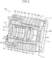
- the structure of the imaging device 10 will now be described with reference to Fig. 2 .
- the lens unit 100 includes a plurality of lenses 101a to 101e, a lens barrel 110, spacing rings 120a to 120d, and a retainer 130.
- the lenses 101a to 101e will be referred to as lenses 101 when they are not distinguished from each other.
- the spacing rings 120a to 120d will be referred to as spacing rings 120 when they are not distinguished from each other.
- the lenses 101a to 101e are arranged in an optical axis direction OA.
- the lenses 101a to 101e are arranged such that optical axes thereof coincide with the optical axis direction OA.
- a direction orthogonal to the optical axis direction OA in a plan view viewed in the optical axis direction OA will be referred to as a radial direction
- a direction that circulates around the optical axis direction OA will be referred to as a circumferential direction.
- the lenses 101 are made of a glass or a resin, such as polycarbonate (PC), cyclo-olefin polymer (COP), cyclo-olefin copolymer (COC), or poly(methyl methacrylate) (PMMA).
- PC polycarbonate
- COP cyclo-olefin polymer
- COC cyclo-olefin copolymer
- PMMA poly(methyl methacrylate)
- the lens barrel 110 is a cylindrical member having an opening 111 larger than the lenses 101a to 105e.
- the lens barrel 110 has an internal space in which the lenses 101 are contained. More specifically, the lens barrel 110 contains the lenses 101a to 101e such that the lens 101e, the lens 101d, the lens 101c, the lens 101b, and the lens 101a are arranged in that order from the opening 111. Thus, among the lenses 101, the lens 101e is closest to the opening 111. In addition, among the lenses 101, the lens 101a is at a side farthest from the opening 111 (hereinafter referred to as "bottom").
- the lens barrel 110 contains the lenses 101 such that the direction of the central axis of the lens barrel 110 coincides with the optical axis direction OA.
- the lens barrel 110 may be made of, for example, aluminum or stainless steel.
- the lens barrel 110 has a thread groove in the outer periphery thereof.
- a housing 11 has a threaded portion configured to engage with the thread groove in the outer periphery of the lens barrel 110.
- the imaging device 10 includes an adhesive member positioned between the thread groove in the outer periphery of the lens barrel 110 and the threaded portion of the housing 11. More specifically, the lens barrel 110 is accommodated in the housing 11 of the imaging device 10 and fixed to the housing 11 at a first fixing section 141.
- the lens barrel 110 is, for example, fixed by being screwed into the housing 11. In this case, a thread crest is formed on an inner peripheral surface of an accommodation space of the housing 11 that accommodates the lens barrel 110 at a position corresponding to the first fixing section 141.
- a thread groove that engages with the thread crest formed in the accommodation space of the housing 11 is formed in an outer peripheral surface of the lens barrel 110 at a position corresponding to the first fixing section 141.
- the adhesive member is applied to at least one of the thread crest on the inner peripheral surface of the accommodation space of the housing 11 and the thread groove in the outer peripheral surface of the lens barrel 110.
- the lens barrel 110 By inserting the lens barrel 110 into the accommodation space of the housing 11 while rotating the lens barrel 110 in the circumferential direction, the lens barrel 110 can be screwed into the accommodation space of the housing 11 such that the thread crest on the inner peripheral surface of the accommodation space of the housing 11 engages with the thread groove in the outer peripheral surface of the lens barrel 110.
- the lens barrel 110 and the housing 11 of the imaging device 10 are fixed by adhesion while the position of the lens barrel 110 is adjusted such that the lenses 101 focus the subject image on the light-receiving surface of the imaging element 200 positioned on an imaging substrate 201.
- the adhesive member is a thermosetting adhesive
- the thermosetting adhesive is cured to fix the lens barrel 110 and the housing 11.
- the first fixing section 141 may, for example, be positioned near the bottom end of the lens barrel 110.
- a filter 202 is positioned between the lens unit 100 and the imaging element 200.
- the filter 202 may be, for example, an ultraviolet (UV)/infrared (IR) cut filter, a color filter, or a low-pass filter.
- the filter 202 may instead be a glass plate having an antireflection (AR) coating.
- the filter 202 is supported by a support portion 203.
- the support portion 203 supports the filter 202.
- the support portion 203 has a sealing structure so that no foreign matter adheres to the light-receiving surface of the imaging element 200.
- a first projecting portion 112 that projects radially outward is formed on the outer peripheral surface of the lens barrel 110.
- the first projecting portion 112 is in contact with the housing 11 with a wave washer 140 provided therebetween when the lens unit 100 is accommodated in the housing 11.
- the wave washer 140 is pressed and urged by the first projecting portion 112 of the lens barrel 110 in the direction in which the lens barrel 110 is inserted.
- the backlash can be reduced by placing the wave washer 140 that is pressed and urged between the first projecting portion 112 of the lens barrel 110 and the housing 11.
- a second projecting portion 113 that projects radially inward is provided on an inner peripheral surface of the lens barrel 110 at the bottom of the lens barrel 110.
- the second projecting portion 113 of the lens barrel 110 has an inner diameter less than the outer diameter of the lens 101a closest to the bottom. Accordingly, the second projecting portion 113 serves as a holder that holds the lens 101a.
- the spacing rings 120 are annular members having an outer diameter substantially equal to the inner diameter of the lens barrel 110 and an inner diameter substantially equal to the outer diameter of a lens portion of each lens 101 described below.
- the spacing rings 120 serve as holders that hold the lenses 101 in the lens barrel 110.
- the spacing rings 120 also serve as spacers positioned between the lenses 101 that are adjacent to each other in the optical axis direction OA to adjust the distances between the adjacent lenses 101 in the optical axis direction OA.
- the spacing ring 120a is positioned between an object-side surface (surface adjacent to the opening 111) of the lens 101a and an image-side surface (surface adjacent to the bottom) of the lens 101b.
- the spacing ring 120b is positioned between an object-side surface of the lens 101b and an image-side surface of the lens 101c.
- the spacing ring 120c is positioned on an object-side surface of the lens 101c.
- the spacing ring 120d is positioned between the spacing ring 120c and an image-side surface of the lens 101d.
- the lens 101e is positioned in contact with an object-side surface of the lens 101d.
- the intervals between the lenses 101 contained in the lens barrel 110 in the optical axis direction OA are adjusted by the spacing rings 120a to 120d.
- the lens barrel 110 has the opening 111 larger than the outer diameters of the lenses 101.
- the second projecting portion 113 which projects radially inward and which is capable of holding the lens 101a closest to the bottom, is provided on the inner peripheral surface of the lens barrel 110 at the bottom of the lens barrel 110. Accordingly, the lens 101a, the spacing ring 120a, the lens 101b, the spacing ring 120b, the lens 101c, the spacing ring 120c, the spacing ring 120d, the lens 101d, and the lens 101e are inserted into the lens barrel 110 through the opening 111 in that order.
- the retainer 130 which serves as a holding member, is in contact with the lens 101e, which is one of the lenses 101 that is closest to the opening 111, and thereby holds the lenses 101 from the side adjacent to the opening 111.
- the retainer 130 includes an outer peripheral portion 131 and a contact portion 132.
- the outer peripheral portion 131 is fixed to the outer peripheral surface of the lens barrel 110.
- the outer peripheral portion 131 is fixed to the outer peripheral surface of the lens barrel 110 at a second fixing section 142, which is closer to the opening 111 than the first projecting portion 112.
- the outer peripheral portion 131 is, for example, fixed by being screwed onto the lens barrel 110.
- a thread crest is formed on the outer peripheral surface of the lens barrel 110 at a position corresponding to the second fixing section 142.
- a thread groove that engages with the thread crest formed on the outer peripheral surface of the lens barrel 110 is formed in an inner peripheral surface of the outer peripheral portion 131 at a position corresponding to the second fixing section 142.
- the retainer 130 is fixed to the outer peripheral surface of the lens barrel 110 by pushing the retainer 130 into the housing 11 in the optical axis direction OA while rotating the retainer 130 in the circumferential direction.
- the contact portion 132 extends radially inward from an end portion of the outer peripheral portion 131 adjacent to the opening 111.
- the contact portion 132 is in contact with the lens 101e closest to the opening 111 and holds the lenses 101 in the optical axis direction OA.
- the structure of the lenses 101 included in the lens unit 100 according to the present embodiment and the manner in which the lenses 101 are held by the retainer 130 will now be described in more detail.
- a problem of a general lens unit including a lens barrel in which a plurality of lenses are held will be described.
- the lens barrel is made of, for example, aluminum.
- the lenses are made of, for example, glass.
- expansion of the lens barrel made of aluminum is greater than expansion of the lenses made of glass. Therefore, when the temperature increases, the lens barrel radially expands, and axial force that holds the lenses in the optical axis direction OA is reduced. As a result, there is a possibility that displacements of the lenses, for example, will occur.
- contraction of the lens barrel made of aluminum is greater than that of the lenses made of glass. Therefore, a large stress is applied to the lenses, and there is a possibility that breakage of the lenses and deformation of components, for example, will occur.
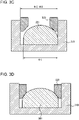
- a lens 301 has a surface that is curved (convex in Fig. 3A ) over the entire area thereof.
- the lens 301 has a surface that is curved over the entire area thereof, it is difficult to hold the lens 301 in a stable manner. The reason for this will be described with reference to Figs. 3A to 3D .
- the lens 301 has an outer diameter ⁇ 1
- a lens barrel 310 that contains the lens 301 has an inner diameter ⁇ 2
- a spacing ring 320 that holds the lens 301 in the lens barrel 310 has an outer diameter ⁇ 3.
- the outer diameter ⁇ 1 of the lens 301, the inner diameter ⁇ 2 of the lens barrel 310, and the outer diameter ⁇ 3 of the spacing ring 320 are substantially equal to each other.
- the lens 301 and the spacing ring 320 are not in line contact with each other but are in point contact with each other in a certain cross section. Therefore, it is difficult to hold the lens 301 in a stable manner.
- the outer diameter ⁇ 3 of the spacing ring 320 is less than the outer diameter ⁇ 1 of the lens 301 and the inner diameter ⁇ 2 of the lens barrel 310 ( ⁇ 3 ⁇ ⁇ 1 ⁇ ⁇ 2).
- contact points between the lens 301 and the spacing ring 320 move in a range corresponding to the difference between the inner diameter ⁇ 2 of the lens barrel 310 and the outer diameter ⁇ 3 of the spacing ring 320 in the radial direction. Therefore, it is difficult to hold the lens 301 in a stable manner.
- the outer diameter ⁇ 1 of the lens 301 is less than the inner diameter ⁇ 2 of the lens barrel 310 and the outer diameter ⁇ 3 of the spacing ring 320 ( ⁇ 1 ⁇ ⁇ 2 ⁇ ⁇ 3).
- the lens 301 and the spacing ring 320 are in contact with each other at only one point in a certain cross section. Therefore, it is difficult to hold the lens 301 in a stable manner.
- Fig. 3D assume that the lens barrel 310 has radially expanded due to high temperature.
- the contact points between the lens 301 and the spacing ring 320 are shifted from those in, for example, Fig. 3A . Therefore, the optical axis of the lens 301 is also shifted.
- the curved surface of the lens 301 is generally mirror finished. Therefore, the frictional force between the lens 301 and the spacing ring 320 is small, which makes it difficult to hold the lens 301 in a stable manner.
- the stability of the lenses 101 contained in the lens barrel 110 is increased by the structure of the lenses 101 and the retainer 130 described in detail below.
- the structure of the retainer 130 will now be described.
- the retainer 130 includes the outer peripheral portion 131 that is fixed to the outer peripheral surface of the lens barrel 110 and the contact portion 132 that extends radially inward from the end portion of the outer peripheral portion 131 adjacent to the opening 111 and that is in contact with the lens 101e.
- a width d2 of the contact portion 132 in the optical axis direction OA is less than a width d1 of the contact portion 132 in the radial direction.
- the contact portion 132 is thin in the optical axis direction OA.
- the contact portion 132 has spring characteristics in the optical axis direction OA.
- the retainer 130 holds the lenses 101 while urging the lenses 101 in the optical axis direction OA
- the stress applied to the lenses 101 due to contraction of the lens barrel 110 can be absorbed when the temperature is low.
- breakage of the lenses 101 and deformation of components, for example can be prevented when the temperature is low, and the lenses 101 contained in the lens barrel 110 can be held in a stable manner.
- the spring constant of the retainer 130 (contact portion 132) in the optical axis direction OA is determined based on various parameters, such as the coefficients of linear expansion of the members that constitute the lenses 101, the sizes of the lenses 101, the coefficient of linear expansion of the member that constitutes the lens barrel 110, the size of the lens barrel 110, and the strength of the member that constitutes the retainer 130.
- the retainer 130 may be designed to have a spring constant such that the stress applied to the lenses 101 due to contraction of the lens barrel 110 can be absorbed when the temperature is low and such that reduction in the axial force due to expansion of the lens barrel 110 can be compensated for when the temperature is high.
- Fig. 4 illustrates a surface of the lens 101 viewed in the optical axis direction OA.
- each lens 101 includes a lens portion 102 and a flat portion 103.
- the lens portion 102 is positioned at the center of the lens 101.
- the lens portion 102 has a convex surface or a concave surface.
- the convex surface or the concave surface of the lens portion 102 refracts light so that the light diverges or converges.
- the flat portion 103 extends radially from the outer edge of the lens 101, and is positioned around the lens portion 102 so as to surround the lens portion 102.
- the flat portion 103 has an annular shape.
- the flat portion 103 is a flat surface that is perpendicular to the optical axis direction OA of the lens 101.
- the lens 101 has an object-side surface and an image-side surface which each include the lens portion 102 and the flat portion 103.
- the lens 101 is held in planar contact with a holder at the flat portion 103.
- the second projecting portion 113 which serves as a holder, has a flat surface perpendicular to the optical axis direction OA.
- the lens 101a is held such that the flat surface of the second projecting portion 113 that is perpendicular to the optical axis direction OA is in planar contact with the flat portion 103 of the image-side surface of the lens 101a.
- the spacing ring 120a which also serves as a holder, has flat surfaces perpendicular to the optical axis direction OA on both the side facing the lens 101a and the side facing the lens 101b.
- the lens 101a is held such that the flat surface on one side of the spacing ring 120a that is perpendicular to the optical axis direction OA is in planar contact with the flat portion 103 of the object-side surface of 101a.
- each of the other lenses 101b to 101e is also held such that the flat portion 103 of each of the object-side surface and the image-side surface is in planar contact with a flat surface of a holder that is perpendicular to the optical axis direction OA.
- the lens 101e closest to the opening 111 is held such that the flat portion 103 of the object-side surface thereof is in contact with the contact portion 132 of the retainer 130, which also serves as a holder.
- Each of the holders that hold the lenses 101 is formed such that the flat surface thereof that is perpendicular to the optical axis direction OA does not come into contact with the lens portion 102 of the corresponding lens 101.
- the lenses 101 can be held without blocking light that travels through the lens portion 102.
- each lens 101 is held in planar contact with a holder (retainer 130, second projecting portion 113, spacing ring 120, or another lens 101), the contact area between the lens 101 and the holder can be increased. In addition, the reliability of transmission of the axial force can be increased. In addition, since each lens 101 is in planar contact with the holder, even when the lens barrel 110 expands due to high temperature, the contact points between the holder and the lens 101 are not shifted in the optical axis direction OA. As a result, the stability of the lenses 101 that are held is increased.
- the lenses 101 have the same outer diameter. Since the lenses 101 have the same outer diameter, the lens barrel 110 may have a constant inner diameter. Since the lens barrel 110 has a constant inner diameter, the spacing rings 120 may have the same size. Thus, the shapes of components of the lens unit 100 can be simplified.
- the lens barrel 110 Since the lens barrel 110 has a constant inner diameter, the axial force that holds the lenses 101 in the optical axis direction OA is linearly transmitted to each of the lens 101 in the optical axis direction OA. Therefore, loss in the axial force can be reduced, and the stability of the lenses 101 that are held can be increased.
- the thickness of the seat can be increased.
- deformation of the seat can be reduced, so that and the stability of the lenses 101 that are held can be increased.
- each of the lenses 101a to 101e is held in planar contact with a holder, which is the retainer 130, the second projecting portion 113, another lens 101, or a spacing ring, at the flat portion 103.
- the outer diameter and the inner diameter of a region in which the lens 101a and the second projecting portion 113 are in planar contact with each other are ⁇ ⁇ 1 and ⁇ i1 , respectively.
- the outer diameter and the inner diameter of a region in which the lens 101a and the spacing ring 120a are in planar contact with each other are ⁇ o2 and ⁇ i2 , respectively.
- the outer diameter and the inner diameter of a region in which the lens 101b and the spacing ring 120a are in planar contact with each other are ⁇ o3 and ⁇ i3 , respectively.
- the outer diameter and the inner diameter of a region in which the lens 101 closest to the object side (lens 101e in the example of Fig. 2 ) and the retainer 130 are in planar contact with each other are ⁇ oN and ⁇ iN , respectively.
- the following expression may be satisfied.
- ⁇ on - ⁇ in corresponds to a portion obtained by removing a portion corresponding to the inner diameter ⁇ in from a portion corresponding to the outer diameter ⁇ on in the sectional view illustrated in Fig. 2 .
- the above expression means that the regions in which the lenses 101 are in planar contact with the respective holders may at least partially overlap when viewed in the optical axis direction OA. More specifically, referring to Fig. 5 , assume that a region in which the lens 101a and the second projecting portion 113 are in planar contact with each other is R 1 . Similarly, assume that a region in which the lens 101e closest to the object side and the lens 101d are in planar contact with each other is R N-1 , and a region in which the lens 101e and the retainer 130 are in planar contact with each other is R N . In this case, there may be an area in which the region R 1 , ..., the region R N-1 , and the region R N all overlap when viewed in the optical axis direction OA.
- the axial force that holds the lenses 101 in the optical axis direction OA may be linearly transmitted to each lens 101 in the optical axis direction OA. Accordingly, the stress applied to the components can be reduced.
- the lens unit 100 includes the plurality of lenses 101 arranged in the optical axis direction OA, the lens barrel 110, and the retainer 130 that serves as a holding member.
- the lens barrel 110 has the opening 111 larger than the outer diameters of the lenses 101 and contains the lenses 101.
- the retainer 130 holds the plurality of lenses 101 by contacting, from a side adjacent to the opening 111 in the lens barrel 110, the lens 101e, which is one of the plurality of lenses 101 that is closest to the opening 111.
- Each lens 101 has an object-side surface and an image-side surface which each include the flat portion 103 that extends radially inward from the outer edge of the lens 101 and that is perpendicular to the optical axis direction OA of the lens 101.
- Each lens 101 is held in planar contact with a holder at the flat portion 103.
- the retainer 130 holds the plurality of lenses 101 by biasing the plurality of lenses 101 in the optical axis direction OA.
- the retainer 130 holds the lenses 101 by applying pressure to the lenses 101 in the optical axis direction OA, the stress applied to the lenses 101 due to contraction of the lens barrel 110 can be absorbed when the temperature is low. In addition, reduction in the axial force applied to the lenses 101 due to expansion of the lens barrel 110 can be compensated for when the temperature is high. In addition, since each lens 101 is held while the flat portion 103 of the lens 101 is in planar contact with the holder, the contact area can be increased and the axial force can be reliably transmitted. In addition, displacements of the optical axis due to expansion of the lens barrel 110, for example, do not easily occur. Accordingly, the stability of the lenses 101 contained in the lens barrel 110 can be increased.
Landscapes
- Physics & Mathematics (AREA)
- General Physics & Mathematics (AREA)
- Optics & Photonics (AREA)
- Engineering & Computer Science (AREA)
- Multimedia (AREA)
- Signal Processing (AREA)
- Lens Barrels (AREA)
- Studio Devices (AREA)
Abstract
Description
- The present application claims priority from
Japanese Patent Application No. 2019-189728 filed in the Japan Patent Office on October 16, 2019 - The present disclosure relates to a lens unit, an imaging device, and a mobile obj ect.
-
PTL 1 discloses a lens barrel device (lens unit) including a lens barrel containing a plurality of lenses arranged in an optical axis direction. - PTL 1:
Japanese Unexamined Patent Application Publication No. 2003-222776 - A lens unit according to the present disclosure includes a plurality of lenses arranged in an optical axis direction, a lens barrel, and a holding member. The lens barrel has an opening larger than outer diameters of the plurality of lenses and contains the plurality of lenses. The holding member holds the plurality of lenses by contacting, from a side adjacent to the opening in the lens barrel, one of the plurality of lenses that is closest to the opening. Each of the plurality of lenses has an object-side surface and an image-side surface which each include a flat portion that extends radially inward from an outer edge of the lens and that is perpendicular to the optical axis direction of the lens. Each of the plurality of lenses is held in planar contact with a holder at the flat portion. The holding member holds the plurality of lenses by biasing the plurality of lenses in the optical axis direction.
- An imaging device according to the present disclosure includes a lens unit and an imaging element. The lens unit includes a plurality of lenses arranged in an optical axis direction, a lens barrel, and a holding member. The imaging element captures a subject image focused by the plurality of lenses. The lens barrel has an opening larger than outer diameters of the plurality of lenses and contains the plurality of lenses. The holding member holds the plurality of lenses by contacting, from a side adjacent to the opening in the lens barrel, one of the plurality of lenses that is closest to the object side. Each of the plurality of lenses has an object-side surface and an image-side surface which each include a flat portion that extends radially inward from an outer edge of the lens and that is perpendicular to the optical axis direction of the lens. Each of the plurality of lenses is held in planar contact with a holder at the flat portion. The holding member holds the plurality of lenses by applying pressure to the plurality of lenses in the optical axis direction.
- A mobile object according to the present disclosure includes an imaging device. The imaging device includes a lens unit and an imaging element. The lens unit includes a plurality of lenses arranged in an optical axis direction, a lens barrel, and a holding member. The imaging element captures a subject image focused by the plurality of lenses. The lens barrel has an opening larger than outer diameters of the plurality of lenses and contains the plurality of lenses. The holding member holds the plurality of lenses by contacting, from a side adjacent to the opening in the lens barrel, one of the plurality of lenses that is closest to the object side. Each of the plurality of lenses has an object-side surface and an image-side surface which each include a flat portion that extends radially inward from an outer edge of the lens and that is perpendicular to the optical axis direction of the lens. Each of the plurality of lenses is held in planar contact with a holder at the flat portion. The holding member holds the plurality of lenses by pressing the plurality of lenses in the optical axis direction.
-
-
Fig. 1 illustrates an exemplary configuration of an imaging device including a lens unit according to an embodiment of the present disclosure. -
Fig. 2 is a sectional view illustrating an exemplary configuration of the imaging device illustrated inFig. 1 . -
Fig. 3A illustrates a problem in holding a lens in a general lens unit. -
Fig. 3B illustrates a problem in holding a lens in a general lens unit. -
Fig. 3C illustrates a problem in holding a lens in a general lens unit. -
Fig. 3D illustrates a problem in holding a lens in a general lens unit. -
Fig. 4 is a plan view illustrating an exemplary configuration of a lens illustrated inFig. 2 . -
Fig. 5 illustrates an example of regions in which each of a plurality of lenses illustrated inFig. 2 is in planar contact with a holder. - In the above-described lens unit, the lenses contained in the lens barrel are required to be held in a stable manner. According to an aspect of the present disclosure, the stability of the lenses held in the lens barrel can be increased.
- An embodiment of the present disclosure will now be described with reference to the drawings. In the drawings, the same reference signs denote the same or similar components. The drawings referred to in the following description are schematic. Dimensional ratios in the drawings, for example, do not necessarily coincide with actual dimensional ratios.
- As illustrated in
Fig. 1 , animaging device 10 including alens unit 100 according to an embodiment of the present disclosure may be mounted in amobile object 1. When theimaging device 10 is mounted in themobile object 1, theimaging device 10 may capture an image of a subject in a space around themobile object 1. The image captured by theimaging device 10 may be used, for example, to detect an object (human, vehicle, etc.) in the space around themobile object 1. - Examples of the
mobile object 1 may include a vehicle and an aircraft. Examples of the vehicle may include an automobile, an industrial vehicle, a railroad vehicle, a daily use vehicle, and a fixed-wing airplane that runs on a runway. Examples of the automobile may include a passenger vehicle, a truck, a bus, a two-wheel vehicle, and a trolley bus. Examples of the industrial vehicle may include an industrial vehicle for agriculture and an industrial vehicle for construction. Examples of the industrial vehicle may include a forklift and a golf cart. Examples of the industrial vehicle for agriculture may include a tractor, a cultivator, a transplanter, a binder, a combine, and a mower. Examples of the industrial vehicle for construction may include a bulldozer, a scraper, an excavator, a crane truck, a dump truck, and a road roller. The vehicle may be a vehicle driven by human force. The categories of the vehicle are not limited to those described above. For example, the automobile may be an industrial vehicle capable of running on a road. The same vehicle may belong to two or more categories. Examples of the aircraft may include a fixed-wing airplane and a rotary wing aircraft. - The
imaging device 10 illustrated inFig. 1 includes thelens unit 100 and animaging element 200. - The
lens unit 100 includes a plurality of optical members, such as lenses. The lenses included in thelens unit 100 may, for example, be lenses having a wide angle of view, such as fisheye lenses. Thelens unit 100 focuses a subject image on a light-receiving surface of theimaging element 200. - The
imaging element 200 includes, for example, a charge coupled device (CCD) image sensor or a complementary metal-oxide semiconductor (CMOS) image sensor. A plurality of pixels (light receiving elements) are arranged on the light-receiving surface of theimaging element 200. Theimaging element 200 captures the subject image focused on the light-receiving surface and creates a captured image. Theimaging device 10 may output the captured image to an external device mounted in themobile object 1. The external device may be, for example, an electronic control unit (ECU), a display, or a navigation device. Theimaging device 10 may have a function of performing a predetermined image process, such as a white balance adjustment process, an exposure adjustment process, or a gamma correction process, on the captured image. - In the example illustrated in
Fig. 1 , theimaging device 10 is a monocular camera including a single imaging system composed of thelens unit 100 and theimaging element 200. However, theimaging device 10 is not limited to this. Theimaging device 10 may instead be a stereo camera that includes a plurality of imaging systems that cooperate with each other to capture images of a target from different visual points. When theimaging device 10 is a stereo camera, twolens units 100, for example, are disposed next to each other with an interval therebetween in a vehicle width direction of themobile object 1 so that optical axes thereof are parallel to each other. Accordingly, the imaging systems capture images of substantially the same area from different visual points. Theimaging device 10 may be fixed to, for example, a front bumper, a fender grille, a side fender, a light module, a hood, etc., of a vehicle. - The structure of the
imaging device 10 will now be described with reference toFig. 2 . - As illustrated in
Fig. 2 , thelens unit 100 includes a plurality oflenses 101a to 101e, alens barrel 110,spacing rings 120a to 120d, and aretainer 130. In the following description, thelenses 101a to 101e will be referred to aslenses 101 when they are not distinguished from each other. Also, thespacing rings 120a to 120d will be referred to as spacing rings 120 when they are not distinguished from each other. - The
lenses 101a to 101e are arranged in an optical axis direction OA. In other words, thelenses 101a to 101e are arranged such that optical axes thereof coincide with the optical axis direction OA. In the following direction, a direction orthogonal to the optical axis direction OA in a plan view viewed in the optical axis direction OA will be referred to as a radial direction, and a direction that circulates around the optical axis direction OA will be referred to as a circumferential direction. - The
lenses 101 are made of a glass or a resin, such as polycarbonate (PC), cyclo-olefin polymer (COP), cyclo-olefin copolymer (COC), or poly(methyl methacrylate) (PMMA). - The
lens barrel 110 is a cylindrical member having anopening 111 larger than thelenses 101a to 105e. Thelens barrel 110 has an internal space in which thelenses 101 are contained. More specifically, thelens barrel 110 contains thelenses 101a to 101e such that thelens 101e, thelens 101d, thelens 101c, thelens 101b, and thelens 101a are arranged in that order from theopening 111. Thus, among thelenses 101, thelens 101e is closest to theopening 111. In addition, among thelenses 101, thelens 101a is at a side farthest from the opening 111 (hereinafter referred to as "bottom"). Thelens barrel 110 contains thelenses 101 such that the direction of the central axis of thelens barrel 110 coincides with the optical axis direction OA. Thelens barrel 110 may be made of, for example, aluminum or stainless steel. - The
lens barrel 110 has a thread groove in the outer periphery thereof. Ahousing 11 has a threaded portion configured to engage with the thread groove in the outer periphery of thelens barrel 110. Theimaging device 10 includes an adhesive member positioned between the thread groove in the outer periphery of thelens barrel 110 and the threaded portion of thehousing 11. More specifically, thelens barrel 110 is accommodated in thehousing 11 of theimaging device 10 and fixed to thehousing 11 at afirst fixing section 141. Thelens barrel 110 is, for example, fixed by being screwed into thehousing 11. In this case, a thread crest is formed on an inner peripheral surface of an accommodation space of thehousing 11 that accommodates thelens barrel 110 at a position corresponding to thefirst fixing section 141. In addition, a thread groove that engages with the thread crest formed in the accommodation space of thehousing 11 is formed in an outer peripheral surface of thelens barrel 110 at a position corresponding to thefirst fixing section 141. The adhesive member is applied to at least one of the thread crest on the inner peripheral surface of the accommodation space of thehousing 11 and the thread groove in the outer peripheral surface of thelens barrel 110. - By inserting the
lens barrel 110 into the accommodation space of thehousing 11 while rotating thelens barrel 110 in the circumferential direction, thelens barrel 110 can be screwed into the accommodation space of thehousing 11 such that the thread crest on the inner peripheral surface of the accommodation space of thehousing 11 engages with the thread groove in the outer peripheral surface of thelens barrel 110. Thelens barrel 110 and thehousing 11 of theimaging device 10 are fixed by adhesion while the position of thelens barrel 110 is adjusted such that thelenses 101 focus the subject image on the light-receiving surface of theimaging element 200 positioned on animaging substrate 201. When the adhesive member is a thermosetting adhesive, the thermosetting adhesive is cured to fix thelens barrel 110 and thehousing 11. As illustrated inFig. 2 , thefirst fixing section 141 may, for example, be positioned near the bottom end of thelens barrel 110. - A
filter 202 is positioned between thelens unit 100 and theimaging element 200. Thefilter 202 may be, for example, an ultraviolet (UV)/infrared (IR) cut filter, a color filter, or a low-pass filter. Thefilter 202 may instead be a glass plate having an antireflection (AR) coating. Thefilter 202 is supported by asupport portion 203. Thesupport portion 203 supports thefilter 202. Thesupport portion 203 has a sealing structure so that no foreign matter adheres to the light-receiving surface of theimaging element 200. - A first projecting
portion 112 that projects radially outward is formed on the outer peripheral surface of thelens barrel 110. The first projectingportion 112 is in contact with thehousing 11 with awave washer 140 provided therebetween when thelens unit 100 is accommodated in thehousing 11. When thelens barrel 110 is inserted into the accommodation space of thehousing 11, thewave washer 140 is pressed and urged by the first projectingportion 112 of thelens barrel 110 in the direction in which thelens barrel 110 is inserted. When thelens barrel 110 is rotated for position adjustment, it may be difficult to perform fine adjustment due to backlash. The backlash can be reduced by placing thewave washer 140 that is pressed and urged between the first projectingportion 112 of thelens barrel 110 and thehousing 11. - A second projecting
portion 113 that projects radially inward is provided on an inner peripheral surface of thelens barrel 110 at the bottom of thelens barrel 110. The second projectingportion 113 of thelens barrel 110 has an inner diameter less than the outer diameter of thelens 101a closest to the bottom. Accordingly, the second projectingportion 113 serves as a holder that holds thelens 101a. - The spacing rings 120 are annular members having an outer diameter substantially equal to the inner diameter of the
lens barrel 110 and an inner diameter substantially equal to the outer diameter of a lens portion of eachlens 101 described below. The spacing rings 120 serve as holders that hold thelenses 101 in thelens barrel 110. The spacing rings 120 also serve as spacers positioned between thelenses 101 that are adjacent to each other in the optical axis direction OA to adjust the distances between theadjacent lenses 101 in the optical axis direction OA. - The
spacing ring 120a is positioned between an object-side surface (surface adjacent to the opening 111) of thelens 101a and an image-side surface (surface adjacent to the bottom) of thelens 101b. Thespacing ring 120b is positioned between an object-side surface of thelens 101b and an image-side surface of thelens 101c. Thespacing ring 120c is positioned on an object-side surface of thelens 101c. Thespacing ring 120d is positioned between thespacing ring 120c and an image-side surface of thelens 101d. Thelens 101e is positioned in contact with an object-side surface of thelens 101d. The intervals between thelenses 101 contained in thelens barrel 110 in the optical axis direction OA are adjusted by thespacing rings 120a to 120d. - As described above, the
lens barrel 110 has theopening 111 larger than the outer diameters of thelenses 101. In addition, the second projectingportion 113, which projects radially inward and which is capable of holding thelens 101a closest to the bottom, is provided on the inner peripheral surface of thelens barrel 110 at the bottom of thelens barrel 110. Accordingly, thelens 101a, thespacing ring 120a, thelens 101b, thespacing ring 120b, thelens 101c, thespacing ring 120c, thespacing ring 120d, thelens 101d, and thelens 101e are inserted into thelens barrel 110 through theopening 111 in that order. - The
retainer 130, which serves as a holding member, is in contact with thelens 101e, which is one of thelenses 101 that is closest to theopening 111, and thereby holds thelenses 101 from the side adjacent to theopening 111. Theretainer 130 includes an outerperipheral portion 131 and acontact portion 132. - The outer
peripheral portion 131 is fixed to the outer peripheral surface of thelens barrel 110. For example, as illustrated inFig. 2 , the outerperipheral portion 131 is fixed to the outer peripheral surface of thelens barrel 110 at asecond fixing section 142, which is closer to theopening 111 than the first projectingportion 112. The outerperipheral portion 131 is, for example, fixed by being screwed onto thelens barrel 110. In this case, for example, a thread crest is formed on the outer peripheral surface of thelens barrel 110 at a position corresponding to thesecond fixing section 142. In addition, a thread groove that engages with the thread crest formed on the outer peripheral surface of thelens barrel 110 is formed in an inner peripheral surface of the outerperipheral portion 131 at a position corresponding to thesecond fixing section 142. Theretainer 130 is fixed to the outer peripheral surface of thelens barrel 110 by pushing theretainer 130 into thehousing 11 in the optical axis direction OA while rotating theretainer 130 in the circumferential direction. - The
contact portion 132 extends radially inward from an end portion of the outerperipheral portion 131 adjacent to theopening 111. When theretainer 130 is fixed to the outer peripheral surface of thelens barrel 110, thecontact portion 132 is in contact with thelens 101e closest to theopening 111 and holds thelenses 101 in the optical axis direction OA. - The structure of the
lenses 101 included in thelens unit 100 according to the present embodiment and the manner in which thelenses 101 are held by theretainer 130 will now be described in more detail. First, a problem of a general lens unit including a lens barrel in which a plurality of lenses are held will be described. - As described above, the lens barrel is made of, for example, aluminum. The lenses are made of, for example, glass. In this case, when the temperature is high, expansion of the lens barrel made of aluminum is greater than expansion of the lenses made of glass. Therefore, when the temperature increases, the lens barrel radially expands, and axial force that holds the lenses in the optical axis direction OA is reduced. As a result, there is a possibility that displacements of the lenses, for example, will occur. When the temperature is low, contraction of the lens barrel made of aluminum is greater than that of the lenses made of glass. Therefore, a large stress is applied to the lenses, and there is a possibility that breakage of the lenses and deformation of components, for example, will occur.
- In a general lens unit, as illustrated in
Fig. 3A , alens 301 has a surface that is curved (convex inFig. 3A ) over the entire area thereof. When thelens 301 has a surface that is curved over the entire area thereof, it is difficult to hold thelens 301 in a stable manner. The reason for this will be described with reference toFigs. 3A to 3D . Referring toFigs. 3A to 3D , assume that thelens 301 has an outer diameter φ1, alens barrel 310 that contains thelens 301 has an inner diameter φ2, and aspacing ring 320 that holds thelens 301 in thelens barrel 310 has an outer diameter φ3. - Referring to
Fig. 3A , assume that the outer diameter φ1 of thelens 301, the inner diameter φ2 of thelens barrel 310, and the outer diameter φ3 of thespacing ring 320 are substantially equal to each other. In this case, since one surface of thelens 301 is curved over the entire area thereof, thelens 301 and thespacing ring 320 are not in line contact with each other but are in point contact with each other in a certain cross section. Therefore, it is difficult to hold thelens 301 in a stable manner. - Referring to
Fig. 3B , assume that the outer diameter φ3 of thespacing ring 320 is less than the outer diameter φ1 of thelens 301 and the inner diameter φ2 of the lens barrel 310 (φ3 < φ1 ≈ φ2). In this case, contact points between thelens 301 and thespacing ring 320 move in a range corresponding to the difference between the inner diameter φ2 of thelens barrel 310 and the outer diameter φ3 of thespacing ring 320 in the radial direction. Therefore, it is difficult to hold thelens 301 in a stable manner. - Referring to
Fig. 3C , assume that the outer diameter φ1 of thelens 301 is less than the inner diameter φ2 of thelens barrel 310 and the outer diameter φ3 of the spacing ring 320 (φ1 < φ2 ≈ φ3). In this case, thelens 301 and thespacing ring 320 are in contact with each other at only one point in a certain cross section. Therefore, it is difficult to hold thelens 301 in a stable manner. - Referring to
Fig. 3D , assume that thelens barrel 310 has radially expanded due to high temperature. In this case, the contact points between thelens 301 and thespacing ring 320 are shifted from those in, for example,Fig. 3A . Therefore, the optical axis of thelens 301 is also shifted. - In addition, the curved surface of the
lens 301 is generally mirror finished. Therefore, the frictional force between thelens 301 and thespacing ring 320 is small, which makes it difficult to hold thelens 301 in a stable manner. - As described above, it is difficult to hold the
lens 301 in a stable manner in the lens unit according to the related art. According to the present disclosure, the stability of thelenses 101 contained in thelens barrel 110 is increased by the structure of thelenses 101 and theretainer 130 described in detail below. The structure of theretainer 130 will now be described. - As described above, the
retainer 130 includes the outerperipheral portion 131 that is fixed to the outer peripheral surface of thelens barrel 110 and thecontact portion 132 that extends radially inward from the end portion of the outerperipheral portion 131 adjacent to theopening 111 and that is in contact with thelens 101e. As illustrated inFig. 2 , a width d2 of thecontact portion 132 in the optical axis direction OA is less than a width d1 of thecontact portion 132 in the radial direction. In other words, thecontact portion 132 is thin in the optical axis direction OA. According to this structure, thecontact portion 132 has spring characteristics in the optical axis direction OA. As a result, when thecontact portion 132 is in contact with thelens 101e closest to theopening 111, theretainer 130 is capable of holding thelenses 101 while urging thelenses 101 in the optical axis direction OA. - When the
retainer 130 holds thelenses 101 while urging thelenses 101 in the optical axis direction OA, the stress applied to thelenses 101 due to contraction of thelens barrel 110 can be absorbed when the temperature is low. As a result, breakage of thelenses 101 and deformation of components, for example, can be prevented when the temperature is low, and thelenses 101 contained in thelens barrel 110 can be held in a stable manner. - In addition, when the
retainer 130 holds thelenses 101 while urging thelenses 101 in the optical axis direction OA, reduction in the axial force applied to thelenses 101 due to expansion of thelens barrel 110 can be compensated for when the temperature is high. As a result, displacements of thelenses 101, for example, can be prevented when the temperature is high, and thelenses 101 contained in thelens barrel 110 can be held in a stable manner. - The spring constant of the retainer 130 (contact portion 132) in the optical axis direction OA is determined based on various parameters, such as the coefficients of linear expansion of the members that constitute the
lenses 101, the sizes of thelenses 101, the coefficient of linear expansion of the member that constitutes thelens barrel 110, the size of thelens barrel 110, and the strength of the member that constitutes theretainer 130. Theretainer 130 may be designed to have a spring constant such that the stress applied to thelenses 101 due to contraction of thelens barrel 110 can be absorbed when the temperature is low and such that reduction in the axial force due to expansion of thelens barrel 110 can be compensated for when the temperature is high. - The structure of each
lens 101 will now be described with reference toFigs. 2 and4. Fig. 4 illustrates a surface of thelens 101 viewed in the optical axis direction OA. - In the present embodiment, each
lens 101 includes alens portion 102 and aflat portion 103. - As illustrated in
Fig. 4 , thelens portion 102 is positioned at the center of thelens 101. Thelens portion 102 has a convex surface or a concave surface. The convex surface or the concave surface of thelens portion 102 refracts light so that the light diverges or converges. - The
flat portion 103 extends radially from the outer edge of thelens 101, and is positioned around thelens portion 102 so as to surround thelens portion 102. In other words, theflat portion 103 has an annular shape. As illustrated inFig. 2 , theflat portion 103 is a flat surface that is perpendicular to the optical axis direction OA of thelens 101. Thelens 101 has an object-side surface and an image-side surface which each include thelens portion 102 and theflat portion 103. Thelens 101 is held in planar contact with a holder at theflat portion 103. - For example, the second projecting
portion 113, which serves as a holder, has a flat surface perpendicular to the optical axis direction OA. Thelens 101a is held such that the flat surface of the second projectingportion 113 that is perpendicular to the optical axis direction OA is in planar contact with theflat portion 103 of the image-side surface of thelens 101a. Thespacing ring 120a, which also serves as a holder, has flat surfaces perpendicular to the optical axis direction OA on both the side facing thelens 101a and the side facing thelens 101b. Thelens 101a is held such that the flat surface on one side of thespacing ring 120a that is perpendicular to the optical axis direction OA is in planar contact with theflat portion 103 of the object-side surface of 101a. Similarly to thelens 101a, each of theother lenses 101b to 101e is also held such that theflat portion 103 of each of the object-side surface and the image-side surface is in planar contact with a flat surface of a holder that is perpendicular to the optical axis direction OA. Thelens 101e closest to theopening 111 is held such that theflat portion 103 of the object-side surface thereof is in contact with thecontact portion 132 of theretainer 130, which also serves as a holder. - Each of the holders that hold the
lenses 101 is formed such that the flat surface thereof that is perpendicular to the optical axis direction OA does not come into contact with thelens portion 102 of thecorresponding lens 101. Thus, thelenses 101 can be held without blocking light that travels through thelens portion 102. - Since each
lens 101 is held in planar contact with a holder (retainer 130, second projectingportion 113, spacing ring 120, or another lens 101), the contact area between thelens 101 and the holder can be increased. In addition, the reliability of transmission of the axial force can be increased. In addition, since eachlens 101 is in planar contact with the holder, even when thelens barrel 110 expands due to high temperature, the contact points between the holder and thelens 101 are not shifted in the optical axis direction OA. As a result, the stability of thelenses 101 that are held is increased. - In the present embodiment, the
lenses 101 have the same outer diameter. Since thelenses 101 have the same outer diameter, thelens barrel 110 may have a constant inner diameter. Since thelens barrel 110 has a constant inner diameter, the spacing rings 120 may have the same size. Thus, the shapes of components of thelens unit 100 can be simplified. - Since the
lens barrel 110 has a constant inner diameter, the axial force that holds thelenses 101 in the optical axis direction OA is linearly transmitted to each of thelens 101 in the optical axis direction OA. Therefore, loss in the axial force can be reduced, and the stability of thelenses 101 that are held can be increased. - In addition, since a portion (seat) of each
lens 101 that is held by a holder has theflat portion 103, which is a flat surface perpendicular to the optical axis direction OA, on each side of thelens 101, the thickness of the seat can be increased. When the thickness of the seat is increased, deformation of the seat can be reduced, so that and the stability of thelenses 101 that are held can be increased. - As described above, each of the
lenses 101a to 101e is held in planar contact with a holder, which is theretainer 130, the second projectingportion 113, anotherlens 101, or a spacing ring, at theflat portion 103. - Assume that the outer diameter and the inner diameter of a region in which the
lens 101a and the second projectingportion 113 are in planar contact with each other are φο1 and φi1, respectively. Assume that the outer diameter and the inner diameter of a region in which thelens 101a and thespacing ring 120a are in planar contact with each other are φo2 and φi2, respectively. Assume that the outer diameter and the inner diameter of a region in which thelens 101b and thespacing ring 120a are in planar contact with each other are φo3 and φi3, respectively. Similarly, assume that the outer diameter and the inner diameter of a region in which thelens 101 closest to the object side (lens 101e in the example ofFig. 2 ) and theretainer 130 are in planar contact with each other are φoN and φiN, respectively. In this case, the following expression may be satisfied.
- In the above expression, when the outer diameter and the inner diameter of the region in which each
lens 101 is in planar contact with a holder are φon and φin, respectively, φon - φin corresponds to a portion obtained by removing a portion corresponding to the inner diameter φin from a portion corresponding to the outer diameter φon in the sectional view illustrated inFig. 2 . - The above expression means that the regions in which the
lenses 101 are in planar contact with the respective holders may at least partially overlap when viewed in the optical axis direction OA. More specifically, referring toFig. 5 , assume that a region in which thelens 101a and the second projectingportion 113 are in planar contact with each other is R1. Similarly, assume that a region in which thelens 101e closest to the object side and thelens 101d are in planar contact with each other is RN-1, and a region in which thelens 101e and theretainer 130 are in planar contact with each other is RN. In this case, there may be an area in which the region R1, ..., the region RN-1, and the region RN all overlap when viewed in the optical axis direction OA. - According to the above-described structure, even when the
lenses 101 have different outer diameters, the axial force that holds thelenses 101 in the optical axis direction OA may be linearly transmitted to eachlens 101 in the optical axis direction OA. Accordingly, the stress applied to the components can be reduced. - As described above, according to the present embodiment, the
lens unit 100 includes the plurality oflenses 101 arranged in the optical axis direction OA, thelens barrel 110, and theretainer 130 that serves as a holding member. Thelens barrel 110 has theopening 111 larger than the outer diameters of thelenses 101 and contains thelenses 101. Theretainer 130 holds the plurality oflenses 101 by contacting, from a side adjacent to theopening 111 in thelens barrel 110, thelens 101e, which is one of the plurality oflenses 101 that is closest to theopening 111. Eachlens 101 has an object-side surface and an image-side surface which each include theflat portion 103 that extends radially inward from the outer edge of thelens 101 and that is perpendicular to the optical axis direction OA of thelens 101. Eachlens 101 is held in planar contact with a holder at theflat portion 103. Theretainer 130 holds the plurality oflenses 101 by biasing the plurality oflenses 101 in the optical axis direction OA. - Since the
retainer 130 holds thelenses 101 by applying pressure to thelenses 101 in the optical axis direction OA, the stress applied to thelenses 101 due to contraction of thelens barrel 110 can be absorbed when the temperature is low. In addition, reduction in the axial force applied to thelenses 101 due to expansion of thelens barrel 110 can be compensated for when the temperature is high. In addition, since eachlens 101 is held while theflat portion 103 of thelens 101 is in planar contact with the holder, the contact area can be increased and the axial force can be reliably transmitted. In addition, displacements of the optical axis due to expansion of thelens barrel 110, for example, do not easily occur. Accordingly, the stability of thelenses 101 contained in thelens barrel 110 can be increased. - Although an embodiment of the present disclosure has been described with reference to the drawings and by way of examples, it is to be noted that various alterations and modifications are possible based on the present disclosure by those skilled in the art. Therefore, these alterations and modifications are to be regarded as being within the scope of the present disclosure.
-
- 1
- mobile object
- 10
- imaging device
- 11
- housing
- 100
- lens unit
- 101, 101a, 101b, 101c, 101d, 101e
- lens
- 102
- lens portion
- 103
- flat portion
- 110
- lens barrel
- 111
- opening
- 112
- first projecting portion
- 113
- second proj ecting portion (holder)
- 120, 120a, 120b, 120c, 120d
- spacing ring (holder)
- 130
- retainer (holding member)
- 131
- outer peripheral portion
- 132
- holding portion
- 140
- wave washer
- 141
- first fixing section
- 142
- second fixing section
- 200
- imaging element
- 201
- imaging substrate
- 202
- filter
- 203
- support portion
Claims (6)
- A lens unit comprising:a plurality of lenses arranged in an optical axis direction;a lens barrel having an opening larger than outer diameters of the plurality of lenses and containing the plurality of lenses; anda holding member that holds the plurality of lenses by contacting, from a side adjacent to the opening in the lens barrel, one of the plurality of lenses that is closest to the opening,wherein each of the plurality of lenses has an object-side surface and an image-side surface which each include a flat portion that extends radially inward from an outer edge of the lens and that is perpendicular to the optical axis direction of the lens,wherein each of the plurality of lenses is held in planar contact with a holder at the flat portion, andwherein the holding member holds the plurality of lenses by biasing the plurality of lenses in the optical axis direction.
- The lens unit according to Claim 1, wherein the outer diameters of the plurality of lenses are equal to each other.
- The lens unit according to Claim 1, wherein the holder with which each of the plurality of lenses is held comprisesthe holding member, a projecting portion that projects radially inward from an inner peripheral surface of the lens barrel,another one of the plurality of lenses that is in contact with the lens, ora spacing ring positioned between the lens and another one of the plurality of lenses that is adjacent to the lens, andwherein regions in which the plurality of lenses are each in planar contact with the holder at least partially overlap when viewed in the optical axis direction.
- The lens unit according to any one of Claims 1 to 3, wherein the holding member includesan outer peripheral portion fixed to an outer peripheral surface of the lens barrel anda contact portion that extends radially inward from an end portion of the outer peripheral portion that is adjacent to the opening, the contact portion being in contact with the one of the plurality of lenses that is closest to the opening, andwherein a width of the contact portion in the optical axis direction is less than a width of the contact portion in a radial direction.
- An imaging device comprising:a lens unit includinga plurality of lenses arranged in an optical axis direction,a lens barrel having an opening larger than outer diameters of the plurality of lenses and containing the plurality of lenses, anda holding member that holds the plurality of lenses by contacting, from a side adjacent to the opening in the lens barrel, one of the plurality of lenses that is closest to an object side; andan imaging element that captures a subject image focused by the plurality of lenses,wherein each of the plurality of lenses has an object-side surface and an image-side surface which each include a flat portion that extends radially inward from an outer edge of the lens and that is perpendicular to the optical axis direction of the lens,wherein each of the plurality of lenses is held in planar contact with a holder at the flat portion, andwherein the holding member holds the plurality of lenses by applying pressure to the plurality of lenses in the optical axis direction.
- A mobile object comprising:a lens unit includinga plurality of lenses arranged in an optical axis direction,a lens barrel having an opening larger than outer diameters of the plurality of lenses and containing the plurality of lenses, anda holding member that holds the plurality of lenses by contacting, from a side adjacent to the opening in the lens barrel, one of the plurality of lenses that is closest to an object side; andan imaging element including an imaging element that captures a subject image focused by the plurality of lenses,wherein each of the plurality of lenses has an object-side surface and an image-side surface which each include a flat portion that extends radially inward from an outer edge of the lens and that is perpendicular to the optical axis direction of the lens,wherein each of the plurality of lenses is held in planar contact with a holder at the flat portion, andwherein the holding member holds the plurality of lenses by pressing the plurality of lenses in the optical axis direction.
Applications Claiming Priority (2)
| Application Number | Priority Date | Filing Date | Title |
|---|---|---|---|
| JP2019189728A JP2021063954A (en) | 2019-10-16 | 2019-10-16 | Lens unit, imaging apparatus, and movable body |
| PCT/JP2020/038285 WO2021075372A1 (en) | 2019-10-16 | 2020-10-09 | Lens unit, imaging device, and mobile object |
Publications (2)
| Publication Number | Publication Date |
|---|---|
| EP4047403A1 true EP4047403A1 (en) | 2022-08-24 |
| EP4047403A4 EP4047403A4 (en) | 2023-11-22 |
Family
ID=75487538
Family Applications (1)
| Application Number | Title | Priority Date | Filing Date |
|---|---|---|---|
| EP20876751.7A Withdrawn EP4047403A4 (en) | 2019-10-16 | 2020-10-09 | Lens unit, imaging device, and mobile object |
Country Status (5)
| Country | Link |
|---|---|
| US (1) | US12292615B2 (en) |
| EP (1) | EP4047403A4 (en) |
| JP (1) | JP2021063954A (en) |
| CN (1) | CN114600023A (en) |
| WO (1) | WO2021075372A1 (en) |
Families Citing this family (3)
| Publication number | Priority date | Publication date | Assignee | Title |
|---|---|---|---|---|
| JP7529422B2 (en) * | 2020-03-30 | 2024-08-06 | ニデックインスツルメンツ株式会社 | Lens unit |
| JP7817025B2 (en) * | 2022-03-11 | 2026-02-18 | 株式会社オプトル | Distance measuring device and moving object |
| DE102025138510A1 (en) | 2024-11-06 | 2026-05-07 | Panasonic Automotive Systems Co., Ltd. | Vehicle camera |
Family Cites Families (22)
| Publication number | Priority date | Publication date | Assignee | Title |
|---|---|---|---|---|
| JPS56156009U (en) * | 1980-04-22 | 1981-11-20 | ||
| JPH075353A (en) * | 1993-04-21 | 1995-01-10 | Asahi Optical Co Ltd | Lens holding structure |
| JP2003222776A (en) | 2002-01-30 | 2003-08-08 | Chinontec Kk | Lens barrel apparatus, camera apparatus and liquid crystal projector apparatus |
| CN1332231C (en) * | 2002-07-01 | 2007-08-15 | 罗姆股份有限公司 | Image Sensor Components |
| JP2006085013A (en) * | 2004-09-17 | 2006-03-30 | Fuji Photo Film Co Ltd | Lens holder and film unit with lens |
| CN1892402A (en) * | 2005-07-09 | 2007-01-10 | 鸿富锦精密工业(深圳)有限公司 | Digital-code camera module |
| WO2008026677A1 (en) * | 2006-08-31 | 2008-03-06 | Sharp Kabushiki Kaisha | Lens holding device |
| US8567678B2 (en) * | 2007-01-30 | 2013-10-29 | Kyocera Corporation | Imaging device, method of production of imaging device, and information code-reading device |
| JP2009205064A (en) * | 2008-02-29 | 2009-09-10 | Sony Corp | Lens barrel and image pickup apparatus |
| CN101587219A (en) * | 2008-05-21 | 2009-11-25 | 鸿富锦精密工业(深圳)有限公司 | Lens module |
| JP2010078920A (en) * | 2008-09-26 | 2010-04-08 | Kyocera Corp | Lens holder |
| CN101846786A (en) * | 2009-03-27 | 2010-09-29 | 杰西迪光学有限公司 | core adjusting device of zoom lens barrel |
| JP6014468B2 (en) * | 2012-11-15 | 2016-10-25 | 京セラ株式会社 | Optical unit and imaging device |
| KR101503982B1 (en) * | 2012-12-21 | 2015-03-18 | 삼성전기주식회사 | Lens module |
| CN109633849B (en) * | 2014-02-12 | 2021-05-14 | 日本电产三协(东莞)工机有限公司 | Image pickup apparatus |
| JP6530215B2 (en) | 2015-03-26 | 2019-06-12 | マクセル株式会社 | Lens unit and camera module |
| CN107783241A (en) * | 2016-08-24 | 2018-03-09 | 宁波舜宇光电信息有限公司 | Lens and Lens Module |
| CN106443941B (en) * | 2016-12-16 | 2019-01-29 | 福建福光天瞳光学有限公司 | F20mm machinery is passively without thermalization LONG WAVE INFRARED tight shot and its focus adjustment method |
| US10379312B2 (en) | 2017-06-02 | 2019-08-13 | Bruker Optik Gmbh | Self-centering lens arrangement for a transmitting, refractive optical unit |
| JP6944283B2 (en) * | 2017-06-27 | 2021-10-06 | 日本電産サンキョー株式会社 | Lens unit and manufacturing method of lens unit |
| US10969660B2 (en) * | 2018-10-25 | 2021-04-06 | Gopro, Inc. | Interchangeable lens structures |
| JP7239435B2 (en) | 2019-10-03 | 2023-03-14 | 京セラ株式会社 | IMAGING DEVICE, MOVING OBJECT, AND METHOD FOR MANUFACTURING IMAGING DEVICE |
-
2019
- 2019-10-16 JP JP2019189728A patent/JP2021063954A/en active Pending
-
2020
- 2020-10-09 EP EP20876751.7A patent/EP4047403A4/en not_active Withdrawn
- 2020-10-09 US US17/754,637 patent/US12292615B2/en active Active
- 2020-10-09 CN CN202080072673.1A patent/CN114600023A/en active Pending
- 2020-10-09 WO PCT/JP2020/038285 patent/WO2021075372A1/en not_active Ceased
Also Published As
| Publication number | Publication date |
|---|---|
| US20220390704A1 (en) | 2022-12-08 |
| WO2021075372A1 (en) | 2021-04-22 |
| CN114600023A (en) | 2022-06-07 |
| JP2021063954A (en) | 2021-04-22 |
| US12292615B2 (en) | 2025-05-06 |
| EP4047403A4 (en) | 2023-11-22 |
Similar Documents
| Publication | Publication Date | Title |
|---|---|---|
| EP4040206A1 (en) | Imaging device, moving body, and imaging device manufacturing method | |
| CN211206934U (en) | Image capturing lens system | |
| US10520696B2 (en) | In-vehicle camera lens unit | |
| US12292615B2 (en) | Lens unit, imaging device, and mobile object | |
| US6597516B2 (en) | Lens frame structure for optical axis adjustment | |
| US7688532B1 (en) | Lens system | |
| JP7588328B2 (en) | Manufacturing method of lens barrel, manufacturing method of holder, lens unit and camera module | |
| EP2069851A2 (en) | Imaging system with relaxed assembly tolerances and associated methods | |
| US12546973B2 (en) | Optical system, image pickup apparatus, in-vehicle system, and moving apparatus | |
| CN119604801A (en) | Optical system and imaging device having the same | |
| WO2020189285A1 (en) | Lens unit | |
| US10893180B2 (en) | Imaging device | |
| US10114191B2 (en) | Lens unit, vehicle-mounted camera, and imaging device | |
| JP7203602B2 (en) | Lens unit and camera module | |
| EP4293405B1 (en) | Imaging lens assembly, camera module and electronic device | |
| JP7835539B2 (en) | Cemented lenses, lens units, camera modules, imaging systems, and mobile bodies | |
| JP2020134761A (en) | Lens unit and camera module | |
| JP2024077842A (en) | Optical system, imaging device equipped with same, and in-vehicle system | |
| KR20190128904A (en) | Optical System for Compact, Long-Wavelength Infrared Camera | |
| CN220085221U (en) | Vehicle-mounted lens | |
| JP7827414B2 (en) | Lens unit, camera module, in-vehicle system and vehicle | |
| US12538007B2 (en) | Lens device, with optical device, imaging device, imaging system, and movable apparatus incorporating same | |
| JP2023107491A (en) | Imaging lens system, camera module, in-vehicle system, moving body | |
| CN120202674A (en) | Camera module and vehicle including the same | |
| JP2020154119A (en) | Lens unit |
Legal Events
| Date | Code | Title | Description |
|---|---|---|---|
| STAA | Information on the status of an ep patent application or granted ep patent |
Free format text: STATUS: THE INTERNATIONAL PUBLICATION HAS BEEN MADE |
|
| PUAI | Public reference made under article 153(3) epc to a published international application that has entered the european phase |
Free format text: ORIGINAL CODE: 0009012 |
|
| STAA | Information on the status of an ep patent application or granted ep patent |
Free format text: STATUS: REQUEST FOR EXAMINATION WAS MADE |
|
| 17P | Request for examination filed |
Effective date: 20220407 |
|
| AK | Designated contracting states |
Kind code of ref document: A1 Designated state(s): AL AT BE BG CH CY CZ DE DK EE ES FI FR GB GR HR HU IE IS IT LI LT LU LV MC MK MT NL NO PL PT RO RS SE SI SK SM TR |
|
| DAV | Request for validation of the european patent (deleted) | ||
| DAX | Request for extension of the european patent (deleted) | ||
| P01 | Opt-out of the competence of the unified patent court (upc) registered |
Effective date: 20230508 |
|
| A4 | Supplementary search report drawn up and despatched |
Effective date: 20231024 |
|
| RIC1 | Information provided on ipc code assigned before grant |
Ipc: G02B 9/60 20060101ALI20231018BHEP Ipc: G03B 15/00 20210101ALI20231018BHEP Ipc: G02B 7/02 20210101AFI20231018BHEP |
|
| STAA | Information on the status of an ep patent application or granted ep patent |
Free format text: STATUS: THE APPLICATION HAS BEEN WITHDRAWN |
|
| 18W | Application withdrawn |
Effective date: 20250711 |