EP4047189A1 - Non-contacting seal assembly with internal coating - Google Patents
Non-contacting seal assembly with internal coating Download PDFInfo
- Publication number
- EP4047189A1 EP4047189A1 EP21214556.9A EP21214556A EP4047189A1 EP 4047189 A1 EP4047189 A1 EP 4047189A1 EP 21214556 A EP21214556 A EP 21214556A EP 4047189 A1 EP4047189 A1 EP 4047189A1
- Authority
- EP
- European Patent Office
- Prior art keywords
- seal
- ring
- shoe
- seal assembly
- assembly
- Prior art date
- Legal status (The legal status is an assumption and is not a legal conclusion. Google has not performed a legal analysis and makes no representation as to the accuracy of the status listed.)
- Pending
Links
- 239000011248 coating agent Substances 0.000 title claims abstract description 50
- 238000000576 coating method Methods 0.000 title claims abstract description 50
- 125000006850 spacer group Chemical group 0.000 claims abstract description 18
- 230000003068 static effect Effects 0.000 claims description 11
- 238000000034 method Methods 0.000 claims description 9
- 239000012530 fluid Substances 0.000 claims description 6
- 229910017052 cobalt Inorganic materials 0.000 claims description 5
- 239000010941 cobalt Substances 0.000 claims description 5
- GUTLYIVDDKVIGB-UHFFFAOYSA-N cobalt atom Chemical compound [Co] GUTLYIVDDKVIGB-UHFFFAOYSA-N 0.000 claims description 5
- 238000004891 communication Methods 0.000 claims description 4
- 239000007789 gas Substances 0.000 description 24
- 239000000463 material Substances 0.000 description 7
- 239000000446 fuel Substances 0.000 description 6
- 239000007921 spray Substances 0.000 description 5
- 239000000567 combustion gas Substances 0.000 description 4
- 230000008569 process Effects 0.000 description 4
- 230000009467 reduction Effects 0.000 description 4
- 229910000990 Ni alloy Inorganic materials 0.000 description 2
- PXHVJJICTQNCMI-UHFFFAOYSA-N Nickel Chemical compound [Ni] PXHVJJICTQNCMI-UHFFFAOYSA-N 0.000 description 2
- 238000002485 combustion reaction Methods 0.000 description 2
- 239000000284 extract Substances 0.000 description 2
- 229910052751 metal Inorganic materials 0.000 description 2
- 239000002184 metal Substances 0.000 description 2
- 230000004044 response Effects 0.000 description 2
- 229910000531 Co alloy Inorganic materials 0.000 description 1
- ZOKXTWBITQBERF-UHFFFAOYSA-N Molybdenum Chemical compound [Mo] ZOKXTWBITQBERF-UHFFFAOYSA-N 0.000 description 1
- 241000237509 Patinopecten sp. Species 0.000 description 1
- 230000003044 adaptive effect Effects 0.000 description 1
- 239000000853 adhesive Substances 0.000 description 1
- 230000001070 adhesive effect Effects 0.000 description 1
- 229910045601 alloy Inorganic materials 0.000 description 1
- 239000000956 alloy Substances 0.000 description 1
- 230000000712 assembly Effects 0.000 description 1
- 238000000429 assembly Methods 0.000 description 1
- 230000008859 change Effects 0.000 description 1
- UFGZSIPAQKLCGR-UHFFFAOYSA-N chromium carbide Chemical compound [Cr]#C[Cr]C#[Cr] UFGZSIPAQKLCGR-UHFFFAOYSA-N 0.000 description 1
- 230000006835 compression Effects 0.000 description 1
- 238000007906 compression Methods 0.000 description 1
- 238000012937 correction Methods 0.000 description 1
- 238000005336 cracking Methods 0.000 description 1
- 238000013461 design Methods 0.000 description 1
- 238000005474 detonation Methods 0.000 description 1
- 230000009977 dual effect Effects 0.000 description 1
- 230000002706 hydrostatic effect Effects 0.000 description 1
- 229910000816 inconels 718 Inorganic materials 0.000 description 1
- 230000007774 longterm Effects 0.000 description 1
- 230000013011 mating Effects 0.000 description 1
- 230000007246 mechanism Effects 0.000 description 1
- 229910001092 metal group alloy Inorganic materials 0.000 description 1
- 230000000116 mitigating effect Effects 0.000 description 1
- 238000012986 modification Methods 0.000 description 1
- 230000004048 modification Effects 0.000 description 1
- 229910052750 molybdenum Inorganic materials 0.000 description 1
- 239000011733 molybdenum Substances 0.000 description 1
- 229910052759 nickel Inorganic materials 0.000 description 1
- 230000010355 oscillation Effects 0.000 description 1
- 239000011435 rock Substances 0.000 description 1
- 235000020637 scallop Nutrition 0.000 description 1
- 229910003470 tongbaite Inorganic materials 0.000 description 1
- 238000012546 transfer Methods 0.000 description 1
- UONOETXJSWQNOL-UHFFFAOYSA-N tungsten carbide Chemical compound [W+]#[C-] UONOETXJSWQNOL-UHFFFAOYSA-N 0.000 description 1
- 229910001247 waspaloy Inorganic materials 0.000 description 1
Images

Classifications
-
- F—MECHANICAL ENGINEERING; LIGHTING; HEATING; WEAPONS; BLASTING
- F01—MACHINES OR ENGINES IN GENERAL; ENGINE PLANTS IN GENERAL; STEAM ENGINES
- F01D—NON-POSITIVE DISPLACEMENT MACHINES OR ENGINES, e.g. STEAM TURBINES
- F01D11/00—Preventing or minimising internal leakage of working-fluid, e.g. between stages
- F01D11/003—Preventing or minimising internal leakage of working-fluid, e.g. between stages by packing rings; Mechanical seals
-
- F—MECHANICAL ENGINEERING; LIGHTING; HEATING; WEAPONS; BLASTING
- F01—MACHINES OR ENGINES IN GENERAL; ENGINE PLANTS IN GENERAL; STEAM ENGINES
- F01D—NON-POSITIVE DISPLACEMENT MACHINES OR ENGINES, e.g. STEAM TURBINES
- F01D11/00—Preventing or minimising internal leakage of working-fluid, e.g. between stages
- F01D11/001—Preventing or minimising internal leakage of working-fluid, e.g. between stages for sealing space between stator blade and rotor
-
- F—MECHANICAL ENGINEERING; LIGHTING; HEATING; WEAPONS; BLASTING
- F16—ENGINEERING ELEMENTS AND UNITS; GENERAL MEASURES FOR PRODUCING AND MAINTAINING EFFECTIVE FUNCTIONING OF MACHINES OR INSTALLATIONS; THERMAL INSULATION IN GENERAL
- F16J—PISTONS; CYLINDERS; SEALINGS
- F16J15/00—Sealings
- F16J15/44—Free-space packings
- F16J15/441—Free-space packings with floating ring
-
- F—MECHANICAL ENGINEERING; LIGHTING; HEATING; WEAPONS; BLASTING
- F01—MACHINES OR ENGINES IN GENERAL; ENGINE PLANTS IN GENERAL; STEAM ENGINES
- F01D—NON-POSITIVE DISPLACEMENT MACHINES OR ENGINES, e.g. STEAM TURBINES
- F01D11/00—Preventing or minimising internal leakage of working-fluid, e.g. between stages
- F01D11/02—Preventing or minimising internal leakage of working-fluid, e.g. between stages by non-contact sealings, e.g. of labyrinth type
- F01D11/025—Seal clearance control; Floating assembly; Adaptation means to differential thermal dilatations
Definitions
- This disclosure relates generally to a gas turbine engine, and more particularly to seal assemblies for use with the gas turbine engine.
- Gas turbine engines typically include a fan delivering air into a compressor, and also outwardly of the compressor as bypass air.
- the air is compressed in the compressor and delivered downstream into a combustion section where it is mixed with fuel and ignited to generate hot combustion gases.
- the hot combustion gases are communicated through the turbine section, which extracts energy from the hot combustion gases to power the compressor section and other gas turbine engine loads. Products of this combustion pass downstream over turbine rotors, driving the turbine rotors to rotate. The turbine rotors in turn rotate the compressors and fan.
- Both the compressor and turbine sections may include alternating series of rotating blades and stationary vanes that extend into the core flow path of the gas turbine engine.
- turbine blades rotate and extract energy from the hot combustion gases that are communicated along the core flow path of the gas turbine engine.
- the turbine vanes which generally do not rotate, guide the airflow and prepare it for the next set of blades.
- the fan and compressor are typically driven by the turbine rotors via shafts. Seals may be provided around the shafts.
- a seal assembly including: a seal, the seal having; a support ring, a shoe, and a beam extending between the shoe and the support ring, wherein the shoe moves relative to the support ring via the beam; a spacer and a second seal; a seal ring; a carrier ring, the second seal being located adjacent to one end of the shoe and the seal ring being located adjacent to an opposite end of the shoe and the carrier ring extends from the seal ring to the spacer, the carrier ring being adjacent to the support ring of the seal; and a wear resistant coating located between a surface of the seal ring and an opposite end of the shoe.
- the wear resistant coating may be located on the surface of the seal ring.
- the wear resistant coating may be located on the opposite end of the shoe.
- the wear resistant coating may be located on the surface of the seal ring and the opposite end of the shoe.
- the seal ring may have a plurality of scalloped openings located between a plurality of tab portions of the seal ring and the wear resistant coating may be located on the plurality of tab portions.
- the wear resistant coating may be located in a notch formed on each of the plurality of tab portions.
- the plurality of scalloped openings may provide fluid communication to the seal.
- the carrier ring and the seal ring may be formed as a single unitary structure.
- the wear resistant coating may be a cobalt based wear coating.
- the secondary seal may comprise a first secondary seal and a second secondary seal.
- a gas turbine engine including: a compressor section; a combustor fluidly connected to the compressor section; a turbine section fluidly connected to the combustor; a seal assembly, located between a rotatable component of the gas turbine engine and a static structure of the gas turbine engine, the seal assembly including: a seal comprising; a support ring, a shoe, and a beam extending between the shoe and the support ring, wherein the shoe moves relative to the support ring via the beam; a spacer and a second seal; a seal ring; a carrier ring, the second seal being located adjacent to one end of the shoe and the seal ring being located adjacent to an opposite end of the shoe and the carrier ring extends from the seal ring to the spacer, the carrier ring being adjacent to the support ring of the seal; and a wear resistant coating located between a surface of the seal ring and an opposite end of the shoe.
- the wear resistant coating may be located on the surface of the seal ring.
- the seal ring may have a plurality of scalloped openings located between a plurality of tab portions of the seal ring and the wear resistant coating may be located on the plurality of tab portions.
- the wear resistant coating may be located in a notch formed on each of the plurality of tab portions.
- the plurality of scalloped openings may provide fluid communication to the seal.
- the wear resistant coating may be a cobalt based wear coating.
- a method of preventing a shoe of a seal assembly from contacting a rotatable component of a gas turbine engine including the steps of: locating a wear resistant coating between a surface of a seal ring and a distal end of a shoe of a seal of a seal assembly of the gas turbine engine, wherein the seal comprises; a support ring and a beam extending between the shoe and the support ring, wherein the shoe moves relative to the support ring via the beam; a spacer and a second seal; a carrier ring, the second seal being located adjacent to one end of the shoe and the seal ring being located adjacent to the distal end of the shoe and the carrier ring extends from the seal ring to the spacer, the carrier ring being adjacent to the support ring of the seal.
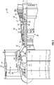
- FIG. 1 schematically illustrates a gas turbine engine 20.
- the gas turbine engine 20 is disclosed herein as a two-spool turbofan that generally incorporates a fan section 22, a compressor section 24, a combustor section 26 and a turbine section 28.
- Alternative engines might include other systems or features.
- the fan section 22 drives air along a bypass flow path B in a bypass duct, while the compressor section 24 drives air along a core flow path C1 for compression and communication into the combustor section 26 then expansion through the turbine section 28.
- the exemplary engine 20 generally includes a low speed spool 30 and a high speed spool 32 mounted for rotation about an engine central longitudinal axis A relative to an engine static structure 36 via several bearing systems 38. It should be understood that various bearing systems 38 at various locations may alternatively or additionally be provided, and the location of bearing systems 38 may be varied as appropriate to the application.
- the low speed spool 30 generally includes an inner shaft 40 that interconnects a fan 42, a first or low pressure compressor 44 and a first or low pressure turbine 46.
- the inner shaft 40 is connected to the fan 42 through a speed change mechanism, which in exemplary gas turbine engine 20 is illustrated as a geared architecture 48 to drive the fan 42 at a lower speed than the low speed spool 30.
- the high speed spool 32 includes an outer shaft 50 that interconnects a second or high pressure compressor 52 and a second or high pressure turbine 54.
- a combustor 56 is arranged in exemplary gas turbine 20 between the high pressure compressor 52 and the high pressure turbine 54.
- a mid-turbine frame 57 of the engine static structure 36 is arranged generally between the high pressure turbine 54 and the low pressure turbine 46.
- the mid-turbine frame 57 further supports bearing systems 38 in the turbine section 28.
- the inner shaft 40 and the outer shaft 50 are concentric and rotate via bearing systems 38 about the engine central longitudinal axis A which is collinear with their longitudinal axe
- the core airflow is compressed by the low pressure compressor 44 then the high pressure compressor 52, mixed and burned with fuel in the combustor 56, then expanded over the high pressure turbine 54 and low pressure turbine 46.
- the mid-turbine frame 57 includes airfoils 59 which are in the core airflow path C.
- the turbines 46, 54 rotationally drive the respective low speed spool 30 and high speed spool 32 in response to the expansion.
- gear system 48 may be located aft of combustor section 26 or even aft of turbine section 28, and fan section 22 may be positioned forward or aft of the location of gear system 48.
- the engine 20 in one example is a high-bypass geared aircraft engine.
- the engine 20 bypass ratio is greater than about six (6), with an example embodiment being greater than about ten (10)
- the geared architecture 48 is an epicyclic gear train, such as a planetary gear system or other gear system, with a gear reduction ratio of greater than about 2.3
- the low pressure turbine 46 has a pressure ratio that is greater than about five.
- the engine 20 bypass ratio is greater than about ten (10:1)
- the fan diameter is significantly larger than that of the low pressure compressor 44
- the low pressure turbine 46 has a pressure ratio that is greater than about five 5:1.
- Low pressure turbine 46 pressure ratio is pressure measured prior to inlet of low pressure turbine 46 as related to the pressure at the outlet of the low pressure turbine 46 prior to an exhaust nozzle.
- the geared architecture 48 may be an epicycle gear train, such as a planetary gear system or other gear system, with a gear reduction ratio of greater than about 2.3:1. It should be understood, however, that the above parameters are only exemplary of one embodiment of a geared architecture engine and that the present disclosure is applicable to other gas turbine engines including direct drive turbofans.
- the fan section 22 of the engine 20 is designed for a particular flight condition--typically cruise at about 0.8 Mach and about 35,000 feet (10,668 meters).
- 'TSFC' Thrust Specific Fuel Consumption
- "Low fan pressure ratio” is the pressure ratio across the fan blade alone, without a Fan Exit Guide Vane (“FEGV”) system.
- the low fan pressure ratio as disclosed herein according to one non-limiting embodiment is less than about 1.45.
- Low corrected fan tip speed is the actual fan tip speed in ft/sec divided by an industry standard temperature correction of [(Tram °R)/(518.7 °R)] 0.5 .
- the "Low corrected fan tip speed” as disclosed herein according to one non-limiting embodiment is less than about 1150 ft/second (350.5 m/sec).
- the fan 42 includes less than about 26 fan blades. In another non-limiting embodiment, the fan 42 includes less than about 20 fan blades.
- the low pressure turbine 46 includes no more than about 6 turbine rotors schematically indicated at 46a. In a further non-limiting example the low pressure turbine 46 includes about 3 turbine rotors. A ratio between the number of blades of the fan 42 and the number of low pressure turbine rotors 46a is between about 3.3 and about 8.6.
- the example low pressure turbine 46 provides the driving power to rotate the fan section 22 and therefore the relationship between the number of turbine rotors 46a in the low pressure turbine 46 and the number of blades in the fan section 22 discloses an example gas turbine engine 20 with increased power transfer efficiency.
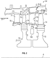
- FIG. 2 illustrates a portion of the high pressure turbine (HPT) 54.
- FIG. 2 also illustrates a high pressure turbine stage vanes 70 one of which (e.g., a first stage vane 71) is located forward of a first one of a pair of turbine disks 72 each having a plurality of turbine blades 74 secured thereto.
- the turbine blades 74 rotate proximate to blade outer air seals (BOAS) 75 which are located aft of the first stage vane 71.
- BOAS blade outer air seals
- the other vane 70 is located between the pair of turbine disks 72. This vane 70 may be referred to as the second stage vane 73.
- the first stage vane 71 is the first vane of the high pressure turbine section 54 that is located aft of the combustor section 26 and the second stage vane 73 is located aft of the first stage vane 71 and is located between the pair of turbine disks 72.
- blade outer air seals (BOAS) 75 are disposed between the first stage vane 71 and the second stage vane 73.
- the high pressure turbine stage vanes 70 e.g., first stage vane 71 or second stage vane 73
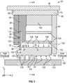
- the seal assembly 80 may include a seal 82, a spacer 84, at least one secondary seal 86, which may comprise a first secondary seal 88 and/or a second secondary seal 90, a secondary seal cover 92, a seal ring 94, and a carrier ring 96.
- a turbine static structure or other static structure 98 of the gas turbine engine may circumferentially surround seal arrangement 80.
- the seal arrangement 80 may be snapped into static structure 98.
- the secondary seal cover 92 may be snapped into carrier ring 96 and the seal ring 94 may be snapped into carrier ring 96.
- seal ring 94 and carrier ring 96 are formed as two separate members. Alternatively, seal ring 94 and carrier ring 96 are formed as a single, monolithic member. In various embodiments, spacer 84 may be snapped into carrier ring 96. In addition, seal 82 may be snapped into carrier ring 96. Still further, seal ring 94 may be snapped into carrier ring 96.
- Seal assembly 80 may circumferentially surround a rotating member or rotatable component 100 of the gas turbine engine.
- the rotating member or rotatable component 100 may be a turbine rotating structure.
- FIG. 2 schematically illustrates one non-limiting location of seal assembly 80 and rotating member 100.
- rotating member 100 may circumferentially surround the seal assembly 80 or be axially adjacent seal assembly 80 without departing from the scope of the present invention as defined by the claims.
- seal 82 may be configured to be coupled within rotating member 100, around rotating member 100, or axially adjacent rotating member 100.
- the rotational axis of rotating member 100 may extend parallel the Z-direction and be located either above (in the positive Y-direction) or below (negative Y-direction) rotating member 100 in FIG. 3 .
- Seal 82 includes a plurality of shoes 102 connected to a support or support ring 104 via one or more beams or arms 106.
- the seal 82 as shown has shoes 102 and a support ring 104.
- the shoes 102 may be disposed radially inward from support ring 104.
- the support ring 104 and the shoes 102 are generally formed from a single piece of metal, and may be cut in order to provide the configurations shown in the FIGS. such that the combined non-contact seal 82 is formed into segments. As shown, the cuts may provide a gap that allows the beams or arms 106 to provide a spring force.
- the shoes 102 may move (e.g., radially) relative to support ring 104 via arms or beams 106.
- seal 82 may comprise a non-contact seal.
- seal 82 may be configured to not physically contact rotating member 100 during certain operational modes of an engine. Stated differently, seal 82 may be configured to maintain a gap between rotating member 100 and the shoe 102.
- seal 82 may physically contact rotating member 100 during certain conditions, such as when the engine is off, or may momentarily contact rotating member 100 during various engine conditions.
- non-contact as used herein, may refer to a seal which utilizes hydrostatic principles to reduce leakage.
- the methods described herein may be used for any suitable seal for increasing seal clearance with respect to a rotating member during assembly without departing from the scope of the present invention as defined by the claims.
- Carrier ring 96 may comprise a distal surface or radially outward surface 108 and static structure 98 may comprise a proximal surface or radial inward surface 110. Distal surface 108 may be in contact proximal surface 110. In various embodiments, carrier ring 96 may be snapped into static structure 98. In various embodiments, carrier ring 96 may be threaded into static structure 98. In other embodiments, carrier ring 96 may attach to the static structure via mechanical means, such as fasteners.
- the seal 82, spacer 84, first secondary seal 88, second secondary seal 90, secondary seal cover 92, seal ring 94 and/or carrier ring 96 may comprise an annular geometry. Seal 82, spacer 84, first secondary seal 88, second secondary seal 90, secondary seal cover 92, seal ring 94 and/or carrier ring 96 may be rings.
- Rotating member 100 may be mounted for rotation about engine central longitudinal axis A.
- rotating member 100 may comprise low speed spool 30.
- rotating member 100 may comprise high speed spool 32.
- rotating member 100 comprises any suitable rotating member incorporating a non-contact seal.
- the non-contact seal may be associated with the turbine section, the compressor section, or the fan section of a gas turbine engine.
- the rotating member 100 may also be a stationary piece.
- seal ring 94 may comprise a scalloped ring 94 (See FIG. 7 ).
- Seal ring 94 may be made from a metal or metal alloy.
- the seal ring may be formed from nickel, nickel alloy or cobalt materials and combinations to meet strength and temperature requirements.
- Other non-limiting materials include: Nickel Alloy 718, INCONEL 718, Waspaloy (Alloy 685).
- seal ring 94 may comprise a plurality of scalloped openings 114 which allow fluid from low pressure side of seal assembly 80 into gap 112 of seal 82.
- the seal 82 includes a shoe 102 attached to the support ring 104 via arms or beams 106.
- the pressure gradient across seal 82 may act to move shoe 102 in the radial direction (Y-direction) illustrated by arrows 116 with respect to support ring 104. This movement may aid in preventing shoe 102 from contacting rotating member 100.
- the shoe 102 of seal 82 may also comprise a plurality of teeth or at least one tooth 118 that extend(s) radially inward from shoe 102.
- High pressure air flow is illustrated generally with arrows 122 while the low pressure air flow is generally illustrated with arrows 124.
- This force balance allows the seal 82 to be adaptive to changing seal gaps and maintain tighter clearances.
- the dual-beam design causes the shoe 102 to move in predominantly radial direction.
- the seal 82 functions by having the shoe 102 moving up and down. An aft or distal end 126 of the shoe 102 rubs against a downstream plate surface 128 of the seal ring 94.
- the seal ring 94 and carrier ring 96 are formed as a unitary single structure.
- the spacer 84 and secondary seal cover 92 are formed as a unitary single structure having a slot 129 into which a portion of the first secondary seal 88 and the second secondary seal 90 are received. This unitary structure with slot 129 may be referred to as spacer 84.
- a wear interface 130 between the shoes 102 and the downstream seal ring, plate or scalloped plate 94 occurs.
- the aft or distal end 126 of the shoe 102 and the downstream plate surface 128 may experience wear and performance of the seal assembly 80 may be negatively impacted.
- the surfaces of the aft or distal end 126 of the shoe 102 and the downstream plate surface 128 may gall and result in sticking and reduction of smooth motion and response.
- the shoes 102/teeth 118 may contact with the rotor or rotating member 100 if they are unable to translate out of the way. Alternatively, the shoes may become stuck in an outboard position, resulting in excessive leakage through the radial gap.
- FIG. 5 also illustrates the delta pressure load in the direction of arrows 132.
- delta pressure load in the direction of arrows 132 refers to the difference between air flows from the high pressure side to the low pressure side in the direction of arrow 120.
- the shoe 102 may rock or rotate in the direction of arrow 134 due to the delta pressure load in the direction of arrows 132. This is undesirable as this may result in the shoe and/or its teeth contacting the rotating member 100 or becoming stuck open and allowing leakage.
- the seal assembly is configured to operate where the delta pressure load in the direction of arrows 132 is in the range of 1 psi (6.9 kPa) to 50 psi (340 kPa).
- Other non-limiting ranges include 50 psi (340 kPa) to 250 psi (1.7 MPa) and 250 psi (1.7 MPa) to 600 psi (4.1 MPa).
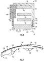
- a wear coating 136 is applied to the downstream plate surface 128, internal to the seal assembly 80.
- the wear coating 136 is applied to tab portions 138 of the scalloped seal ring 94.
- the wear coating 136 is applied to the downstream plate surface 128 of the seal ring 94 and in particular on the tab portions 138 that are location on opposite sides of the scallop openings 114.
- a notch 140 is formed in the tab portions 138 prior to the application of wear coating 136.
- the wear coating may be deposited in the notch 140 formed in the downstream plate surface 128 of tab portions 138 of the seal ring 94.
- a thickness "W" (see FIG. 6 ) of the wear coating 136 in an axial direction is in the range of 0.002" (0.05 mm) to 0.015" (0.38 mm).
- Other non-limiting ranges for the thickness "W" of the wear coating 136 include but are not limited to 0.002" (0.05 mm) to 0.005" (0.13 mm); 0.005" (0.13 mm) to 0.010" (0.25 mm); and 0.010" (0.25 mm) to 0.015" (0.38 mm).
- the wear coating 136 is a cobalt based wear coating.
- Other non-limiting examples of wear coating 136 include but are not limited to chromium carbide, tungsten carbide, molybdenum, cobalt alloys, and equivalents thereof.
- the wear coating 136 may be applied by a plasma spray process, flame spray, dual wire arc thermal spray, detonation gun, thermal spray process or a high velocity oxy-fuel (HVOF) thermal spray process or other thermal processes.
- a plasma spray process flame spray, dual wire arc thermal spray, detonation gun, thermal spray process or a high velocity oxy-fuel (HVOF) thermal spray process or other thermal processes.
- HVOF high velocity oxy-fuel
- the wear coating 136 reduces friction between the shoes 102 and downstream plate surface 128, and further reduces the long term wear between the mating surfaces of the shoes 102 and the seal ring 94.
- the wear coating 136 is applied prior to assembly of the seal assembly 80 and is contained within the seal assembly 80.
- the wear coating 136 allows the surfaces of the shoes 102 and the seal ring 94 to slide more freely and reduce the chance of adhesion between the two surfaces.
- the wear coating also prevent adhesive wear to the shoes 102 and/or the seal ring 94. This reduces the probability of the shoes 102 and/or their associated teeth 118 from contacting the rotor 100 thereby mitigating rotor damage and/or failure of the seal assembly 80.
- the reduction in wear rate also results in increased life of the seal assembly 80 and the wear coating 136 can reduce friction and improve performance of the seal 80.
- the wear coating 136 may be specific to certain environments the seal 82 is exposed to. Through use of different wear coating materials the wear coating 136 allows the coefficient of friction between the shoes 102 and the seal ring 96 to be tuned such that the seal 82 behaves in an optimal fashion.
- the seal 82 can also be optimized to minimize excessive vibrations and associated high cycle fatigue (HCF, e.g., a structural assessment of the amount of vibrational oscillations the seal can experience before cracking or failure), as well as impact, while maintaining its ability to adapt to changing gaps.
- HCF high cycle fatigue
- the coating material 136 can be chosen to obtain a coefficient of friction against the seal ring 94, which in one non-limiting embodiment is 0.1 to 0.3. Other non-limiting ranges for such a coefficient of friction include but are not limited to 0.3 to 0.5 and 0.5 to 0.8.
- the material of the seal ring 94 and the carrier ring 96 may be optimized and the seal ring 94 and the carrier ring 96 are formed as a single, monolithic member with the optimized material as there is no longer a concern that the distal end 126 of the shoes 102 will stick to the downstream plate surface 128.
- the wear coating 136 may be applied to the distal end 126 of the shoes 102 instead of the downstream plate surface 128 of the tabs portions 138 of the seal ring 94 or alternatively, the wear coating 136 may be applied to both the distal end 126 of the shoes 102 and the downstream plate surface 128 of the tabs portions 138 of the seal ring 94.
Landscapes
- Engineering & Computer Science (AREA)
- General Engineering & Computer Science (AREA)
- Mechanical Engineering (AREA)
- Structures Of Non-Positive Displacement Pumps (AREA)
Abstract
Description
- This disclosure relates generally to a gas turbine engine, and more particularly to seal assemblies for use with the gas turbine engine.
- Gas turbine engines typically include a fan delivering air into a compressor, and also outwardly of the compressor as bypass air. The air is compressed in the compressor and delivered downstream into a combustion section where it is mixed with fuel and ignited to generate hot combustion gases. The hot combustion gases are communicated through the turbine section, which extracts energy from the hot combustion gases to power the compressor section and other gas turbine engine loads. Products of this combustion pass downstream over turbine rotors, driving the turbine rotors to rotate. The turbine rotors in turn rotate the compressors and fan.
- Both the compressor and turbine sections may include alternating series of rotating blades and stationary vanes that extend into the core flow path of the gas turbine engine. For example, in the turbine section, turbine blades rotate and extract energy from the hot combustion gases that are communicated along the core flow path of the gas turbine engine. The turbine vanes, which generally do not rotate, guide the airflow and prepare it for the next set of blades.
- The fan and compressor are typically driven by the turbine rotors via shafts. Seals may be provided around the shafts.
- According to a first aspect there is provided a seal assembly, including: a seal, the seal having; a support ring, a shoe, and a beam extending between the shoe and the support ring, wherein the shoe moves relative to the support ring via the beam; a spacer and a second seal; a seal ring; a carrier ring, the second seal being located adjacent to one end of the shoe and the seal ring being located adjacent to an opposite end of the shoe and the carrier ring extends from the seal ring to the spacer, the carrier ring being adjacent to the support ring of the seal; and a wear resistant coating located between a surface of the seal ring and an opposite end of the shoe.
- Optionally, the wear resistant coating may be located on the surface of the seal ring.
- Optionally, the wear resistant coating may be located on the opposite end of the shoe.
- Optionally, the wear resistant coating may be located on the surface of the seal ring and the opposite end of the shoe.
- Optionally, the seal ring may have a plurality of scalloped openings located between a plurality of tab portions of the seal ring and the wear resistant coating may be located on the plurality of tab portions.
- Optionally, the wear resistant coating may be located in a notch formed on each of the plurality of tab portions.
- Optionally, the plurality of scalloped openings may provide fluid communication to the seal.
- Optionally, the carrier ring and the seal ring may be formed as a single unitary structure.
- Optionally, the wear resistant coating may be a cobalt based wear coating.
- Optionally, the secondary seal may comprise a first secondary seal and a second secondary seal.
- According to another aspect there is provided a gas turbine engine, including: a compressor section; a combustor fluidly connected to the compressor section; a turbine section fluidly connected to the combustor; a seal assembly, located between a rotatable component of the gas turbine engine and a static structure of the gas turbine engine, the seal assembly including: a seal comprising; a support ring, a shoe, and a beam extending between the shoe and the support ring, wherein the shoe moves relative to the support ring via the beam; a spacer and a second seal; a seal ring; a carrier ring, the second seal being located adjacent to one end of the shoe and the seal ring being located adjacent to an opposite end of the shoe and the carrier ring extends from the seal ring to the spacer, the carrier ring being adjacent to the support ring of the seal; and a wear resistant coating located between a surface of the seal ring and an opposite end of the shoe.
- Optionally, the wear resistant coating may be located on the surface of the seal ring.
- Optionally, the seal ring may have a plurality of scalloped openings located between a plurality of tab portions of the seal ring and the wear resistant coating may be located on the plurality of tab portions.
- Optionally, the wear resistant coating may be located in a notch formed on each of the plurality of tab portions.
- Optionally, the plurality of scalloped openings may provide fluid communication to the seal.
- Optionally, the wear resistant coating may be a cobalt based wear coating.
- According to another aspect there is provided a method of preventing a shoe of a seal assembly from contacting a rotatable component of a gas turbine engine, the method including the steps of: locating a wear resistant coating between a surface of a seal ring and a distal end of a shoe of a seal of a seal assembly of the gas turbine engine, wherein the seal comprises; a support ring and a beam extending between the shoe and the support ring, wherein the shoe moves relative to the support ring via the beam; a spacer and a second seal; a carrier ring, the second seal being located adjacent to one end of the shoe and the seal ring being located adjacent to the distal end of the shoe and the carrier ring extends from the seal ring to the spacer, the carrier ring being adjacent to the support ring of the seal.
- The following descriptions should not be considered limiting in any way. With reference to the accompanying drawings, like elements are numbered alike:
-
FIG. 1 is a schematic, partial cross-sectional view of a gas turbine engine; -
FIG. 2 is a schematic view of a two-stage high pressure turbine of the gas turbine engine; -
FIG. 3 is a cross-sectional view of a non-contacting seal assembly; -
FIG. 4 is a view along lines 4-4 ofFIG. 3 ; -
FIG. 5 is a cross-sectional view of a non-contacting seal assembly; -
FIG. 6 is a cross-sectional view of a non-contacting seal assembly; and -
FIG. 7 is a perspective view of a portion of a non-contacting seal assembly. - A detailed description of one or more embodiments of the disclosed apparatus and method are presented herein by way of exemplification and not limitation with reference to the FIGS.
-
FIG. 1 schematically illustrates agas turbine engine 20. Thegas turbine engine 20 is disclosed herein as a two-spool turbofan that generally incorporates afan section 22, acompressor section 24, acombustor section 26 and aturbine section 28. Alternative engines might include other systems or features. Thefan section 22 drives air along a bypass flow path B in a bypass duct, while thecompressor section 24 drives air along a core flow path C1 for compression and communication into thecombustor section 26 then expansion through theturbine section 28. Although depicted as a two-spool turbofan gas turbine engine in the disclosed non-limiting embodiment, it should be understood that the concepts described herein are not limited to use with two-spool turbofans as the teachings may be applied to other types of turbine engines including three-spool architectures. - The
exemplary engine 20 generally includes alow speed spool 30 and ahigh speed spool 32 mounted for rotation about an engine central longitudinal axis A relative to an enginestatic structure 36 viaseveral bearing systems 38. It should be understood thatvarious bearing systems 38 at various locations may alternatively or additionally be provided, and the location ofbearing systems 38 may be varied as appropriate to the application. - The
low speed spool 30 generally includes aninner shaft 40 that interconnects afan 42, a first orlow pressure compressor 44 and a first orlow pressure turbine 46. Theinner shaft 40 is connected to thefan 42 through a speed change mechanism, which in exemplarygas turbine engine 20 is illustrated as a gearedarchitecture 48 to drive thefan 42 at a lower speed than thelow speed spool 30. Thehigh speed spool 32 includes anouter shaft 50 that interconnects a second orhigh pressure compressor 52 and a second orhigh pressure turbine 54. Acombustor 56 is arranged inexemplary gas turbine 20 between thehigh pressure compressor 52 and thehigh pressure turbine 54. Amid-turbine frame 57 of the enginestatic structure 36 is arranged generally between thehigh pressure turbine 54 and thelow pressure turbine 46. Themid-turbine frame 57 further supports bearingsystems 38 in theturbine section 28. Theinner shaft 40 and theouter shaft 50 are concentric and rotate viabearing systems 38 about the engine central longitudinal axis A which is collinear with their longitudinal axes. - The core airflow is compressed by the
low pressure compressor 44 then thehigh pressure compressor 52, mixed and burned with fuel in thecombustor 56, then expanded over thehigh pressure turbine 54 andlow pressure turbine 46. Themid-turbine frame 57 includesairfoils 59 which are in the core airflow path C. Theturbines low speed spool 30 andhigh speed spool 32 in response to the expansion. It will be appreciated that each of the positions of thefan section 22,compressor section 24,combustor section 26,turbine section 28, and fandrive gear system 48 may be varied. For example,gear system 48 may be located aft ofcombustor section 26 or even aft ofturbine section 28, andfan section 22 may be positioned forward or aft of the location ofgear system 48. - The
engine 20 in one example is a high-bypass geared aircraft engine. In a further example, theengine 20 bypass ratio is greater than about six (6), with an example embodiment being greater than about ten (10), the gearedarchitecture 48 is an epicyclic gear train, such as a planetary gear system or other gear system, with a gear reduction ratio of greater than about 2.3 and thelow pressure turbine 46 has a pressure ratio that is greater than about five. In one disclosed embodiment, theengine 20 bypass ratio is greater than about ten (10:1), the fan diameter is significantly larger than that of thelow pressure compressor 44, and thelow pressure turbine 46 has a pressure ratio that is greater than about five 5:1.Low pressure turbine 46 pressure ratio is pressure measured prior to inlet oflow pressure turbine 46 as related to the pressure at the outlet of thelow pressure turbine 46 prior to an exhaust nozzle. The gearedarchitecture 48 may be an epicycle gear train, such as a planetary gear system or other gear system, with a gear reduction ratio of greater than about 2.3:1. It should be understood, however, that the above parameters are only exemplary of one embodiment of a geared architecture engine and that the present disclosure is applicable to other gas turbine engines including direct drive turbofans. - A significant amount of thrust is provided by the bypass flow B due to the high bypass ratio. The
fan section 22 of theengine 20 is designed for a particular flight condition--typically cruise at about 0.8 Mach and about 35,000 feet (10,668 meters). The flight condition of 0.8 Mach and 35,000 ft (10,668 meters), with the engine at its best fuel consumption--also known as "bucket cruise Thrust Specific Fuel Consumption ('TSFC')"--is the industry standard parameter of pound-mass (lbm) of fuel per hour being burned divided by pound-force (lbf) of thrust the engine produces at that minimum point. "Low fan pressure ratio" is the pressure ratio across the fan blade alone, without a Fan Exit Guide Vane ("FEGV") system. The low fan pressure ratio as disclosed herein according to one non-limiting embodiment is less than about 1.45. "Low corrected fan tip speed" is the actual fan tip speed in ft/sec divided by an industry standard temperature correction of [(Tram °R)/(518.7 °R)]0.5. The "Low corrected fan tip speed" as disclosed herein according to one non-limiting embodiment is less than about 1150 ft/second (350.5 m/sec). - In a further example, the
fan 42 includes less than about 26 fan blades. In another non-limiting embodiment, thefan 42 includes less than about 20 fan blades. Moreover, in one further embodiment thelow pressure turbine 46 includes no more than about 6 turbine rotors schematically indicated at 46a. In a further non-limiting example thelow pressure turbine 46 includes about 3 turbine rotors. A ratio between the number of blades of thefan 42 and the number of lowpressure turbine rotors 46a is between about 3.3 and about 8.6. The examplelow pressure turbine 46 provides the driving power to rotate thefan section 22 and therefore the relationship between the number ofturbine rotors 46a in thelow pressure turbine 46 and the number of blades in thefan section 22 discloses an examplegas turbine engine 20 with increased power transfer efficiency. -
FIG. 2 illustrates a portion of the high pressure turbine (HPT) 54.FIG. 2 also illustrates a high pressureturbine stage vanes 70 one of which (e.g., a first stage vane 71) is located forward of a first one of a pair ofturbine disks 72 each having a plurality ofturbine blades 74 secured thereto. Theturbine blades 74 rotate proximate to blade outer air seals (BOAS) 75 which are located aft of thefirst stage vane 71. Theother vane 70 is located between the pair ofturbine disks 72. Thisvane 70 may be referred to as thesecond stage vane 73. As used herein thefirst stage vane 71 is the first vane of the highpressure turbine section 54 that is located aft of thecombustor section 26 and thesecond stage vane 73 is located aft of thefirst stage vane 71 and is located between the pair ofturbine disks 72. In addition, blade outer air seals (BOAS) 75 are disposed between thefirst stage vane 71 and thesecond stage vane 73. The high pressure turbine stage vanes 70 (e.g.,first stage vane 71 or second stage vane 73) are one of a plurality ofvanes 70 that are positioned circumferentially about the axis A of the engine in order to provide astator assembly 76. Hot gases from thecombustor section 26 flow through the turbine in the direction of arrow 77. Although a two-stage high pressure turbine is illustrated other high pressure turbines are considered to be within the scope of various embodiments of the present disclosure as defined by the claims. - Referring now to
FIG. 3 , a cross-section view of aseal assembly 80 is illustrated. Theseal assembly 80 may include aseal 82, aspacer 84, at least onesecondary seal 86, which may comprise a firstsecondary seal 88 and/or a secondsecondary seal 90, asecondary seal cover 92, aseal ring 94, and acarrier ring 96. In various embodiments, a turbine static structure or otherstatic structure 98 of the gas turbine engine may circumferentially surroundseal arrangement 80. In addition, theseal arrangement 80 may be snapped intostatic structure 98. Thesecondary seal cover 92 may be snapped intocarrier ring 96 and theseal ring 94 may be snapped intocarrier ring 96. - In one embodiment,
seal ring 94 andcarrier ring 96 are formed as two separate members. Alternatively,seal ring 94 andcarrier ring 96 are formed as a single, monolithic member. In various embodiments,spacer 84 may be snapped intocarrier ring 96. In addition,seal 82 may be snapped intocarrier ring 96. Still further,seal ring 94 may be snapped intocarrier ring 96. -
Seal assembly 80 may circumferentially surround a rotating member orrotatable component 100 of the gas turbine engine. In one embodiment, the rotating member orrotatable component 100 may be a turbine rotating structure.FIG. 2 schematically illustrates one non-limiting location ofseal assembly 80 and rotatingmember 100. - However and in one alternative, it is contemplated that the rotating
member 100 may circumferentially surround theseal assembly 80 or be axiallyadjacent seal assembly 80 without departing from the scope of the present invention as defined by the claims. In this regard, seal 82 may be configured to be coupled within rotatingmember 100, around rotatingmember 100, or axially adjacent rotatingmember 100. In this regard, the rotational axis of rotatingmember 100 may extend parallel the Z-direction and be located either above (in the positive Y-direction) or below (negative Y-direction) rotatingmember 100 inFIG. 3 . -
Seal 82 includes a plurality ofshoes 102 connected to a support orsupport ring 104 via one or more beams orarms 106. Theseal 82 as shown hasshoes 102 and asupport ring 104. In various embodiments, theshoes 102 may be disposed radially inward fromsupport ring 104. In one embodiment, thesupport ring 104 and theshoes 102 are generally formed from a single piece of metal, and may be cut in order to provide the configurations shown in the FIGS. such that the combinednon-contact seal 82 is formed into segments. As shown, the cuts may provide a gap that allows the beams orarms 106 to provide a spring force. Theshoes 102 may move (e.g., radially) relative to supportring 104 via arms or beams 106. - As described herein, seal 82 may comprise a non-contact seal. In this regard, seal 82 may be configured to not physically contact rotating
member 100 during certain operational modes of an engine. Stated differently, seal 82 may be configured to maintain a gap between rotatingmember 100 and theshoe 102. However, it should be noted thatseal 82 may physically contact rotatingmember 100 during certain conditions, such as when the engine is off, or may momentarily contact rotatingmember 100 during various engine conditions. In this regard, the term "non-contact," as used herein, may refer to a seal which utilizes hydrostatic principles to reduce leakage. Furthermore, it is contemplated that the methods described herein may be used for any suitable seal for increasing seal clearance with respect to a rotating member during assembly without departing from the scope of the present invention as defined by the claims. -
Carrier ring 96 may comprise a distal surface or radiallyoutward surface 108 andstatic structure 98 may comprise a proximal surface or radialinward surface 110.Distal surface 108 may be in contactproximal surface 110. In various embodiments,carrier ring 96 may be snapped intostatic structure 98. In various embodiments,carrier ring 96 may be threaded intostatic structure 98. In other embodiments,carrier ring 96 may attach to the static structure via mechanical means, such as fasteners. - In one embodiment, the
seal 82,spacer 84, firstsecondary seal 88, secondsecondary seal 90,secondary seal cover 92,seal ring 94 and/orcarrier ring 96 may comprise an annular geometry.Seal 82,spacer 84, firstsecondary seal 88, secondsecondary seal 90,secondary seal cover 92,seal ring 94 and/orcarrier ring 96 may be rings. - Rotating
member 100 may be mounted for rotation about engine central longitudinal axis A. In various embodiments, rotatingmember 100 may compriselow speed spool 30. In various embodiments, rotatingmember 100 may comprisehigh speed spool 32. In various embodiments, rotatingmember 100 comprises any suitable rotating member incorporating a non-contact seal. For example, the non-contact seal may be associated with the turbine section, the compressor section, or the fan section of a gas turbine engine. In other non-limiting embodiments, the rotatingmember 100 may also be a stationary piece. - With reference to at least
FIG. 3 , a fluid, such as air for example, may travel from the high pressure side ofseal assembly 80 to the low pressure side ofseal assembly 80. Firstsecondary seal 88 and secondsecondary seal 90 may prevent fluid from high pressure side ofseal arrangement 80 from entering agap 112 ofseal 82. In various embodiments,seal ring 94 may comprise a scalloped ring 94 (SeeFIG. 7 ).Seal ring 94 may be made from a metal or metal alloy. In one non-limiting embodiment, the seal ring may be formed from nickel, nickel alloy or cobalt materials and combinations to meet strength and temperature requirements. Other non-limiting materials include: Nickel Alloy 718, INCONEL 718, Waspaloy (Alloy 685). In this regard,seal ring 94 may comprise a plurality ofscalloped openings 114 which allow fluid from low pressure side ofseal assembly 80 intogap 112 ofseal 82. - As mentioned above, the
seal 82 includes ashoe 102 attached to thesupport ring 104 via arms or beams 106. In this regard, it should be appreciated that the pressure gradient acrossseal 82 may act to moveshoe 102 in the radial direction (Y-direction) illustrated byarrows 116 with respect to supportring 104. This movement may aid in preventingshoe 102 from contacting rotatingmember 100. Theshoe 102 ofseal 82 may also comprise a plurality of teeth or at least onetooth 118 that extend(s) radially inward fromshoe 102. - As illustrated in at least
FIG. 4 , air flows from the high pressure side to the low pressure side in the direction ofarrow 120. High pressure air flow is illustrated generally witharrows 122 while the low pressure air flow is generally illustrated witharrows 124. - As the air flows
past teeth 118 in the direction ofarrow 120 the pressure field changes from high to low. Balance between the high and low pressure sides causes theshoe 102 to actuate up and down in the direction ofarrows 116, until equilibrium is achieved. As such, theshoe 102 swings onbeams 106 and actuates up and down. - This force balance allows the
seal 82 to be adaptive to changing seal gaps and maintain tighter clearances. In addition, the dual-beam design causes theshoe 102 to move in predominantly radial direction. - Since the
seal 82 functions by having theshoe 102 moving up and down. An aft ordistal end 126 of theshoe 102 rubs against adownstream plate surface 128 of theseal ring 94. As illustrated inFIG. 5 , theseal ring 94 andcarrier ring 96 are formed as a unitary single structure. In addition and as illustrated inFIG. 5 , thespacer 84 andsecondary seal cover 92 are formed as a unitary single structure having aslot 129 into which a portion of the firstsecondary seal 88 and the secondsecondary seal 90 are received. This unitary structure withslot 129 may be referred to asspacer 84. - As illustrated in
FIG. 5 , awear interface 130 between theshoes 102 and the downstream seal ring, plate or scallopedplate 94 occurs. Over time, the aft ordistal end 126 of theshoe 102 and thedownstream plate surface 128 may experience wear and performance of theseal assembly 80 may be negatively impacted. For example, the surfaces of the aft ordistal end 126 of theshoe 102 and thedownstream plate surface 128 may gall and result in sticking and reduction of smooth motion and response. As such, theshoes 102/teeth 118 may contact with the rotor or rotatingmember 100 if they are unable to translate out of the way. Alternatively, the shoes may become stuck in an outboard position, resulting in excessive leakage through the radial gap. -
FIG. 5 also illustrates the delta pressure load in the direction ofarrows 132. As used herein, delta pressure load in the direction ofarrows 132 refers to the difference between air flows from the high pressure side to the low pressure side in the direction ofarrow 120. - As such and if the aft or
distal end 126 of theshoe 102 and thedownstream plate surface 128 stick preventing motion in the direction ofarrows 116 theshoe 102 may rock or rotate in the direction ofarrow 134 due to the delta pressure load in the direction ofarrows 132. This is undesirable as this may result in the shoe and/or its teeth contacting the rotatingmember 100 or becoming stuck open and allowing leakage. - In accordance with one non-limiting embodiment, the seal assembly is configured to operate where the delta pressure load in the direction of
arrows 132 is in the range of 1 psi (6.9 kPa) to 50 psi (340 kPa). Other non-limiting ranges include 50 psi (340 kPa) to 250 psi (1.7 MPa) and 250 psi (1.7 MPa) to 600 psi (4.1 MPa). - Referring now to
FIGS. 6 and 7 and in order to prevent the aforementioned sticking of theshoe 102, awear coating 136 is applied to thedownstream plate surface 128, internal to theseal assembly 80. In one embodiment, thewear coating 136 is applied totab portions 138 of thescalloped seal ring 94. In other words, thewear coating 136 is applied to thedownstream plate surface 128 of theseal ring 94 and in particular on thetab portions 138 that are location on opposite sides of thescallop openings 114. In addition and in order to provide a receiving area forwear coating 136, anotch 140 is formed in thetab portions 138 prior to the application ofwear coating 136. Thus, the wear coating may be deposited in thenotch 140 formed in thedownstream plate surface 128 oftab portions 138 of theseal ring 94. - In one non-limiting embodiment, a thickness "W" (see
FIG. 6 ) of thewear coating 136 in an axial direction (e.g., from thenotch 140 to a surface of thewear coating 136 that contacts the aft ordistal end 126 of theshoe 102 is in the range of 0.002" (0.05 mm) to 0.015" (0.38 mm). Other non-limiting ranges for the thickness "W" of thewear coating 136 include but are not limited to 0.002" (0.05 mm) to 0.005" (0.13 mm); 0.005" (0.13 mm) to 0.010" (0.25 mm); and 0.010" (0.25 mm) to 0.015" (0.38 mm). - In one non-limiting embodiment, the
wear coating 136 is a cobalt based wear coating. Other non-limiting examples ofwear coating 136 include but are not limited to chromium carbide, tungsten carbide, molybdenum, cobalt alloys, and equivalents thereof. - In one non-limiting embodiment, the
wear coating 136 may be applied by a plasma spray process, flame spray, dual wire arc thermal spray, detonation gun, thermal spray process or a high velocity oxy-fuel (HVOF) thermal spray process or other thermal processes. - The
wear coating 136 reduces friction between theshoes 102 anddownstream plate surface 128, and further reduces the long term wear between the mating surfaces of theshoes 102 and theseal ring 94. - In one non-limiting embodiment, the
wear coating 136 is applied prior to assembly of theseal assembly 80 and is contained within theseal assembly 80. - As mentioned above, the
wear coating 136 allows the surfaces of theshoes 102 and theseal ring 94 to slide more freely and reduce the chance of adhesion between the two surfaces. In addition, the wear coating also prevent adhesive wear to theshoes 102 and/or theseal ring 94. This reduces the probability of theshoes 102 and/or their associatedteeth 118 from contacting therotor 100 thereby mitigating rotor damage and/or failure of theseal assembly 80. The reduction in wear rate also results in increased life of theseal assembly 80 and thewear coating 136 can reduce friction and improve performance of theseal 80. - In one non-limiting embodiment, the
wear coating 136 may be specific to certain environments theseal 82 is exposed to. Through use of different wear coating materials thewear coating 136 allows the coefficient of friction between theshoes 102 and theseal ring 96 to be tuned such that theseal 82 behaves in an optimal fashion. Theseal 82 can also be optimized to minimize excessive vibrations and associated high cycle fatigue (HCF, e.g., a structural assessment of the amount of vibrational oscillations the seal can experience before cracking or failure), as well as impact, while maintaining its ability to adapt to changing gaps. - Depending on the seal delta Pressure (dP) difference between high pressure and low pressure across the
seal 82 in the direction ofarrow 120 the operating environment the seal is employed, thecoating material 136 can be chosen to obtain a coefficient of friction against theseal ring 94, which in one non-limiting embodiment is 0.1 to 0.3. Other non-limiting ranges for such a coefficient of friction include but are not limited to 0.3 to 0.5 and 0.5 to 0.8. - Through the use of
wear coating 136 the material of theseal ring 94 and thecarrier ring 96 may be optimized and theseal ring 94 and thecarrier ring 96 are formed as a single, monolithic member with the optimized material as there is no longer a concern that thedistal end 126 of theshoes 102 will stick to thedownstream plate surface 128. - In an alternative embodiment, the
wear coating 136 may be applied to thedistal end 126 of theshoes 102 instead of thedownstream plate surface 128 of thetabs portions 138 of theseal ring 94 or alternatively, thewear coating 136 may be applied to both thedistal end 126 of theshoes 102 and thedownstream plate surface 128 of thetabs portions 138 of theseal ring 94. - The terminology used herein is for the purpose of describing particular embodiments only and is not intended to be limiting of the present disclosure. As used herein, the singular forms "a", "an" and "the" are intended to include the plural forms as well, unless the context clearly indicates otherwise. It will be further understood that the terms "comprises" and/or "comprising," when used in this specification, specify the presence of stated features, integers, steps, operations, elements, and/or components, but do not preclude the presence or addition of one or more other features, integers, steps, operations, element components, and/or groups thereof.
- While the present invention has been described with reference to an exemplary embodiment or embodiments, it will be understood by those skilled in the art that various changes may be made and equivalents may be substituted for elements thereof without departing from the scope of the present invention as defined by the claims. In addition, many modifications may be made to adapt a particular situation or material to the teachings of the present disclosure without departing from the scope of the claims. Therefore, it is intended that the present invention not be limited to the particular embodiment disclosed as the best mode contemplated for carrying out this present disclosure, but that the present invention will include all embodiments falling within the scope of the claims.
Claims (11)
- A seal assembly (80), comprising:a seal (82) comprising; a support ring (104), a shoe (102), and a beam (106) extending between the shoe and the support ring, wherein the shoe moves relative to the support ring via the beam;a spacer (84) and a second seal (86; 88, 90);a seal ring (94);a carrier ring (96), the second seal being located adjacent to one end of the shoe (102) and the seal ring being located adjacent to an opposite end (126) of the shoe and the carrier ring extends from the seal ring to the spacer, the carrier ring being adjacent to the support ring (104) of the seal (82); anda wear resistant coating (136) located between a surface (128) of the seal ring (94) and the opposite end of the shoe.
- The seal assembly as in claim 1, wherein the wear resistant coating (136) is located on the surface (128) of the seal ring (94).
- The seal assembly as in claim 1 or 2, wherein the wear resistant coating (136) is located on the opposite end (126) of the shoe (102).
- The seal assembly as in any preceding claim, wherein the seal ring (94) has a plurality of scalloped openings (114) located between a plurality of tab portions (138) of the seal ring and the wear resistant coating (136) is located on the plurality of tab portions.
- The seal assembly as in claim 4, wherein the wear resistant coating (136) is located in a notch (140) formed on each of the plurality of tab portions (138).
- The seal assembly as in claim 4 or 5, wherein the plurality of scalloped openings (114) provide fluid communication to the seal (82).
- The seal assembly as in any preceding claim, wherein the carrier ring (96) and the seal ring (94) are formed as a single unitary structure.
- The seal assembly as in any preceding claim, wherein the wear resistant coating (136) is a cobalt based wear coating.
- The seal assembly as in any preceding claim, wherein the secondary seal (86) comprises a first secondary seal (88) and a second secondary seal (90).
- A gas turbine engine (20) comprising:a compressor section (24);a combustor (56) fluidly connected to the compressor section;a turbine section (28) fluidly connected to the combustor;the seal assembly (80) as in any preceding claim, located between a rotatable component (100) of the gas turbine engine and a static structure of the gas turbine engine.
- A method of preventing a shoe (102) of a seal assembly (80) from contacting a rotatable component (100) of a gas turbine engine (20), comprising:
locating a wear resistant coating (136) between a surface (128) of a seal ring (94) and a distal end (126) of the shoe (102) of a seal (82) of the seal assembly (80) of the gas turbine engine (20), wherein the seal comprises; a support ring (104) and a beam (106) extending between the shoe and the support ring, wherein the shoe moves relative to the support ring via the beam; a spacer (84) and a second seal (86; 88, 90); a carrier ring (96), the second seal being located adjacent to one end of the shoe (102) and the seal ring (94) being located adjacent to the distal end (126) of the shoe and the carrier ring extends from the seal ring to the spacer (84), the carrier ring being adjacent to the support ring (104) of the seal (82).
Applications Claiming Priority (1)
| Application Number | Priority Date | Filing Date | Title |
|---|---|---|---|
| US17/179,645 US20220268166A1 (en) | 2021-02-19 | 2021-02-19 | Non-contacting seal assembly with internal coating |
Publications (1)
| Publication Number | Publication Date |
|---|---|
| EP4047189A1 true EP4047189A1 (en) | 2022-08-24 |
Family
ID=78916861
Family Applications (1)
| Application Number | Title | Priority Date | Filing Date |
|---|---|---|---|
| EP21214556.9A Pending EP4047189A1 (en) | 2021-02-19 | 2021-12-14 | Non-contacting seal assembly with internal coating |
Country Status (2)
| Country | Link |
|---|---|
| US (1) | US20220268166A1 (en) |
| EP (1) | EP4047189A1 (en) |
Families Citing this family (1)
| Publication number | Priority date | Publication date | Assignee | Title |
|---|---|---|---|---|
| US12180840B1 (en) * | 2024-01-08 | 2024-12-31 | General Electric Company | Seal assembly for a turbine engine |
Citations (5)
| Publication number | Priority date | Publication date | Assignee | Title |
|---|---|---|---|---|
| US20140117624A1 (en) * | 2012-10-31 | 2014-05-01 | General Electric Company | Pressure actuated film riding seals for turbo machinery |
| US20160010480A1 (en) * | 2014-07-08 | 2016-01-14 | General Electric Company | Film riding seal assembly for turbomachinery |
| US20180066533A1 (en) * | 2016-09-02 | 2018-03-08 | United Technologies Corporation | Halo seal attached secondary seal cover arrangement |
| EP3677817A1 (en) * | 2019-01-03 | 2020-07-08 | United Technologies Corporation | Hydrostatic seal with extended housing |
| US10731496B2 (en) * | 2018-01-17 | 2020-08-04 | Raytheon Technologies Corporation | Bearing-supported seal |
Family Cites Families (35)
| Publication number | Priority date | Publication date | Assignee | Title |
|---|---|---|---|---|
| US4871297A (en) * | 1987-04-08 | 1989-10-03 | Westinghouse Electric Corp. | Reactor coolant pump sealing surfaces with titanium nitride coating |
| US4942059A (en) * | 1988-09-29 | 1990-07-17 | Westinghouse Electric Corp. | Method for hardfacing metal articles |
| US8382119B2 (en) * | 2006-08-15 | 2013-02-26 | General Electric Company | Compliant plate seals for turbomachinery |
| US9410556B2 (en) * | 2012-06-11 | 2016-08-09 | United Technologies Corporation | Ring seal midplate |
| WO2014143284A1 (en) * | 2013-03-15 | 2014-09-18 | United Technologies Corporation | Vibration damping apparatus for hydrostatic seal of gas turbine engine |
| WO2015147967A1 (en) * | 2014-03-27 | 2015-10-01 | United Technologies Corporation | Gas turbine engine and seal assembly therefore |
| US9963991B2 (en) * | 2014-10-01 | 2018-05-08 | United Technologies Corporation | Brush seal plate |
| US10801348B2 (en) * | 2014-10-14 | 2020-10-13 | Raytheon Technologies Corporation | Non-contacting dynamic seal |
| US20160109025A1 (en) * | 2014-10-21 | 2016-04-21 | United Technologies Corporation | Seal ring |
| US10358932B2 (en) * | 2015-06-29 | 2019-07-23 | United Technologies Corporation | Segmented non-contact seal assembly for rotational equipment |
| US10221714B2 (en) * | 2016-01-22 | 2019-03-05 | United Technologies Corporation | Secondary seal device(s) with alignment tab(s) |
| US10030531B2 (en) * | 2016-01-22 | 2018-07-24 | United Technologies Corporation | Seal shoe for a hydrostatic non-contact seal device |
| US10060535B2 (en) * | 2016-02-25 | 2018-08-28 | United Technologies Corporation | Shaped spring element for a non-contact seal device |
| US10961860B2 (en) * | 2016-08-15 | 2021-03-30 | Raytheon Technologies Corporation | Non-contact seal with removal features |
| US10100657B2 (en) * | 2016-08-15 | 2018-10-16 | United Technologies Corporation | Non-contact seal with monolithic/unitary carrier structure |
| US10370996B2 (en) * | 2016-08-23 | 2019-08-06 | United Technologies Corporation | Floating, non-contact seal with offset build clearance for load imbalance |
| US10385715B2 (en) * | 2016-08-29 | 2019-08-20 | United Technologies Corporation | Floating, non-contact seal with angled beams |
| US10550708B2 (en) * | 2016-08-31 | 2020-02-04 | United Technologies Corporation | Floating, non-contact seal with at least three beams |
| US10415413B2 (en) * | 2016-09-01 | 2019-09-17 | United Technologies Corporation | Floating non-contact seal vertical lip |
| US10718270B2 (en) * | 2017-06-15 | 2020-07-21 | Raytheon Technologies Corporation | Hydrostatic non-contact seal with dual material |
| US10641180B2 (en) * | 2017-06-15 | 2020-05-05 | United Technologies Corporation | Hydrostatic non-contact seal with varied thickness beams |
| US10337621B2 (en) * | 2017-06-23 | 2019-07-02 | United Technologies Corporation | Hydrostatic non-contact seal with weight reduction pocket |
| US10731761B2 (en) * | 2017-07-14 | 2020-08-04 | Raytheon Technologies Corporation | Hydrostatic non-contact seal with offset outer ring |
| US20190017404A1 (en) * | 2017-07-14 | 2019-01-17 | United Technologies Corporation | Hydrostatic non-contact seal with seal carrier elimination |
| US10830081B2 (en) * | 2017-07-17 | 2020-11-10 | Raytheon Technologies Corporation | Non-contact seal with non-straight spring beam(s) |
| US10422431B2 (en) * | 2017-07-17 | 2019-09-24 | United Technologies Corporation | Non-contact seal with progressive radial stop(s) |
| US10184347B1 (en) * | 2017-07-18 | 2019-01-22 | United Technologies Corporation | Non-contact seal with resilient biasing element(s) |
| US11047481B2 (en) * | 2017-09-06 | 2021-06-29 | General Electric Company | Seal assembly for a rotary machine |
| US10746039B2 (en) * | 2017-09-25 | 2020-08-18 | United Technologies Corporation | Hydrostatic seal pinned cartridge |
| US10626744B2 (en) * | 2017-09-29 | 2020-04-21 | United Technologies Corporation | Dual hydorstatic seal assembly |
| US10760442B2 (en) * | 2018-01-12 | 2020-09-01 | Raytheon Technologies Corporation | Non-contact seal with angled land |
| US10822983B2 (en) * | 2018-02-06 | 2020-11-03 | Raytheon Technologies Corportation | Hydrostatic seal with abradable teeth for gas turbine engine |
| US10731497B2 (en) * | 2018-02-07 | 2020-08-04 | Raytheon Technologies Corporation | Separate secondary seal support rail for seal |
| CN113167126B (en) * | 2018-10-09 | 2023-05-02 | 西门子能源全球两合公司 | Secondary seal in a non-contact seal assembly |
| US11230940B1 (en) * | 2020-08-31 | 2022-01-25 | Raytheon Technologies Corporation | Controlled contact surface for a secondary seal in a non-contact seal assembly |
-
2021
- 2021-02-19 US US17/179,645 patent/US20220268166A1/en not_active Abandoned
- 2021-12-14 EP EP21214556.9A patent/EP4047189A1/en active Pending
Patent Citations (5)
| Publication number | Priority date | Publication date | Assignee | Title |
|---|---|---|---|---|
| US20140117624A1 (en) * | 2012-10-31 | 2014-05-01 | General Electric Company | Pressure actuated film riding seals for turbo machinery |
| US20160010480A1 (en) * | 2014-07-08 | 2016-01-14 | General Electric Company | Film riding seal assembly for turbomachinery |
| US20180066533A1 (en) * | 2016-09-02 | 2018-03-08 | United Technologies Corporation | Halo seal attached secondary seal cover arrangement |
| US10731496B2 (en) * | 2018-01-17 | 2020-08-04 | Raytheon Technologies Corporation | Bearing-supported seal |
| EP3677817A1 (en) * | 2019-01-03 | 2020-07-08 | United Technologies Corporation | Hydrostatic seal with extended housing |
Also Published As
| Publication number | Publication date |
|---|---|
| US20220268166A1 (en) | 2022-08-25 |
Similar Documents
| Publication | Publication Date | Title |
|---|---|---|
| EP3543469B1 (en) | Blade outer air seal assembly with feather seal | |
| EP3290646B1 (en) | Floating, non-contact seal with angled beams for use in aircraft engines | |
| EP2990699B1 (en) | Dual-ended brush seal assembly and method of manufacture | |
| US11168574B2 (en) | Segmented non-contact seal assembly for rotational equipment | |
| EP3783201B1 (en) | Rotor assembly for a gas turbine engine and corresponding method of sealing | |
| EP3073055B1 (en) | Damper for stator assembly and stator assembly | |
| EP2949874B1 (en) | Dual walled seal assembly | |
| EP3521572B1 (en) | Hydrostatic seal assembly with abradable teeth for gas turbine engine | |
| EP3039252B1 (en) | Variable vane bushing | |
| US10487943B2 (en) | Multi-ply seal ring | |
| EP3653915B1 (en) | Seal disassembly aid | |
| EP3102810B1 (en) | Gas turbine circumferential axial segmented trough seal | |
| EP3734019A1 (en) | Labyrinth seal with passive check valve | |
| EP3587740B1 (en) | Seal assembly for a gas turbine engine and method of assembling | |
| EP3524780B1 (en) | Hydrostatic seal assembly for a gas turbine engine and corresponding gas turbine engine | |
| EP3748135B1 (en) | Bushing for variable vane in a gas turbine engine | |
| EP4047189A1 (en) | Non-contacting seal assembly with internal coating | |
| EP4484712A1 (en) | Annular seal with interlocked rings | |
| EP4386179A1 (en) | Gas turbine engine with split helical piston seal | |
| EP4006310B1 (en) | Face seal arrangement with reduced balance ratio | |
| EP3608512A1 (en) | Gas turbine engine with sealing surface for blade outer air seal | |
| EP3181828B1 (en) | Blade outer air seal with integrated air shield | |
| US11352892B2 (en) | Seal element for sealing a joint between a rotor blade and a rotor disk | |
| EP3862534B1 (en) | Blade with wearable tip-rub-portions above squealer pocket |
Legal Events
| Date | Code | Title | Description |
|---|---|---|---|
| PUAI | Public reference made under article 153(3) epc to a published international application that has entered the european phase |
Free format text: ORIGINAL CODE: 0009012 |
|
| STAA | Information on the status of an ep patent application or granted ep patent |
Free format text: STATUS: THE APPLICATION HAS BEEN PUBLISHED |
|
| AK | Designated contracting states |
Kind code of ref document: A1 Designated state(s): AL AT BE BG CH CY CZ DE DK EE ES FI FR GB GR HR HU IE IS IT LI LT LU LV MC MK MT NL NO PL PT RO RS SE SI SK SM TR |
|
| STAA | Information on the status of an ep patent application or granted ep patent |
Free format text: STATUS: REQUEST FOR EXAMINATION WAS MADE |
|
| 17P | Request for examination filed |
Effective date: 20230224 |
|
| RBV | Designated contracting states (corrected) |
Designated state(s): AL AT BE BG CH CY CZ DE DK EE ES FI FR GB GR HR HU IE IS IT LI LT LU LV MC MK MT NL NO PL PT RO RS SE SI SK SM TR |
|
| RAP3 | Party data changed (applicant data changed or rights of an application transferred) |
Owner name: RTX CORPORATION |
|
| STAA | Information on the status of an ep patent application or granted ep patent |
Free format text: STATUS: EXAMINATION IS IN PROGRESS |
|
| 17Q | First examination report despatched |
Effective date: 20240424 |