EP4047185B1 - Leitschaufel mit flansch aus einer querlenkerförmigen faserschichtstruktur - Google Patents
Leitschaufel mit flansch aus einer querlenkerförmigen faserschichtstruktur Download PDFInfo
- Publication number
- EP4047185B1 EP4047185B1 EP22158268.7A EP22158268A EP4047185B1 EP 4047185 B1 EP4047185 B1 EP 4047185B1 EP 22158268 A EP22158268 A EP 22158268A EP 4047185 B1 EP4047185 B1 EP 4047185B1
- Authority
- EP
- European Patent Office
- Prior art keywords
- fiber
- flange
- cavity
- plies
- recited
- Prior art date
- Legal status (The legal status is an assumption and is not a legal conclusion. Google has not performed a legal analysis and makes no representation as to the accuracy of the status listed.)
- Active
Links
Images


Classifications
-
- F—MECHANICAL ENGINEERING; LIGHTING; HEATING; WEAPONS; BLASTING
- F01—MACHINES OR ENGINES IN GENERAL; ENGINE PLANTS IN GENERAL; STEAM ENGINES
- F01D—NON-POSITIVE DISPLACEMENT MACHINES OR ENGINES, e.g. STEAM TURBINES
- F01D5/00—Blades; Blade-carrying members; Heating, heat-insulating, cooling or antivibration means on the blades or the members
- F01D5/12—Blades
- F01D5/14—Form or construction
- F01D5/147—Construction, i.e. structural features, e.g. of weight-saving hollow blades
-
- F—MECHANICAL ENGINEERING; LIGHTING; HEATING; WEAPONS; BLASTING
- F01—MACHINES OR ENGINES IN GENERAL; ENGINE PLANTS IN GENERAL; STEAM ENGINES
- F01D—NON-POSITIVE DISPLACEMENT MACHINES OR ENGINES, e.g. STEAM TURBINES
- F01D9/00—Stators
- F01D9/06—Fluid supply conduits to nozzles or the like
- F01D9/065—Fluid supply or removal conduits traversing the working fluid flow, e.g. for lubrication-, cooling-, or sealing fluids
-
- B—PERFORMING OPERATIONS; TRANSPORTING
- B29—WORKING OF PLASTICS; WORKING OF SUBSTANCES IN A PLASTIC STATE IN GENERAL
- B29B—PREPARATION OR PRETREATMENT OF THE MATERIAL TO BE SHAPED; MAKING GRANULES OR PREFORMS; RECOVERY OF PLASTICS OR OTHER CONSTITUENTS OF WASTE MATERIAL CONTAINING PLASTICS
- B29B11/00—Making preforms
- B29B11/14—Making preforms characterised by structure or composition
- B29B11/16—Making preforms characterised by structure or composition comprising fillers or reinforcement
-
- C—CHEMISTRY; METALLURGY
- C04—CEMENTS; CONCRETE; ARTIFICIAL STONE; CERAMICS; REFRACTORIES
- C04B—LIME, MAGNESIA; SLAG; CEMENTS; COMPOSITIONS THEREOF, e.g. MORTARS, CONCRETE OR LIKE BUILDING MATERIALS; ARTIFICIAL STONE; CERAMICS; REFRACTORIES; TREATMENT OF NATURAL STONE
- C04B35/00—Shaped ceramic products characterised by their composition; Ceramics compositions; Processing powders of inorganic compounds preparatory to the manufacturing of ceramic products
- C04B35/515—Shaped ceramic products characterised by their composition; Ceramics compositions; Processing powders of inorganic compounds preparatory to the manufacturing of ceramic products based on non-oxide ceramics
- C04B35/56—Shaped ceramic products characterised by their composition; Ceramics compositions; Processing powders of inorganic compounds preparatory to the manufacturing of ceramic products based on non-oxide ceramics based on carbides or oxycarbides
- C04B35/565—Shaped ceramic products characterised by their composition; Ceramics compositions; Processing powders of inorganic compounds preparatory to the manufacturing of ceramic products based on non-oxide ceramics based on carbides or oxycarbides based on silicon carbide
- C04B35/573—Shaped ceramic products characterised by their composition; Ceramics compositions; Processing powders of inorganic compounds preparatory to the manufacturing of ceramic products based on non-oxide ceramics based on carbides or oxycarbides based on silicon carbide obtained by reaction sintering or recrystallisation
-
- C—CHEMISTRY; METALLURGY
- C04—CEMENTS; CONCRETE; ARTIFICIAL STONE; CERAMICS; REFRACTORIES
- C04B—LIME, MAGNESIA; SLAG; CEMENTS; COMPOSITIONS THEREOF, e.g. MORTARS, CONCRETE OR LIKE BUILDING MATERIALS; ARTIFICIAL STONE; CERAMICS; REFRACTORIES; TREATMENT OF NATURAL STONE
- C04B35/00—Shaped ceramic products characterised by their composition; Ceramics compositions; Processing powders of inorganic compounds preparatory to the manufacturing of ceramic products
- C04B35/71—Ceramic products containing macroscopic reinforcing agents
- C04B35/78—Ceramic products containing macroscopic reinforcing agents containing non-metallic materials
- C04B35/80—Fibres, filaments, whiskers, platelets, or the like
-
- C—CHEMISTRY; METALLURGY
- C22—METALLURGY; FERROUS OR NON-FERROUS ALLOYS; TREATMENT OF ALLOYS OR NON-FERROUS METALS
- C22C—ALLOYS
- C22C47/00—Making alloys containing metallic or non-metallic fibres or filaments
- C22C47/08—Making alloys containing metallic or non-metallic fibres or filaments by contacting the fibres or filaments with molten metal, e.g. by infiltrating the fibres or filaments placed in a mould
-
- D—TEXTILES; PAPER
- D03—WEAVING
- D03D—WOVEN FABRICS; METHODS OF WEAVING; LOOMS
- D03D1/00—Woven fabrics designed to make specified articles
-
- D—TEXTILES; PAPER
- D03—WEAVING
- D03D—WOVEN FABRICS; METHODS OF WEAVING; LOOMS
- D03D11/00—Double or multi-ply fabrics not otherwise provided for
- D03D11/02—Fabrics formed with pockets, tubes, loops, folds, tucks or flaps
-
- D—TEXTILES; PAPER
- D03—WEAVING
- D03D—WOVEN FABRICS; METHODS OF WEAVING; LOOMS
- D03D25/00—Woven fabrics not otherwise provided for
- D03D25/005—Three-dimensional woven fabrics
-
- F—MECHANICAL ENGINEERING; LIGHTING; HEATING; WEAPONS; BLASTING
- F01—MACHINES OR ENGINES IN GENERAL; ENGINE PLANTS IN GENERAL; STEAM ENGINES
- F01D—NON-POSITIVE DISPLACEMENT MACHINES OR ENGINES, e.g. STEAM TURBINES
- F01D9/00—Stators
- F01D9/02—Nozzles; Nozzle boxes; Stator blades; Guide conduits, e.g. individual nozzles
- F01D9/04—Nozzles; Nozzle boxes; Stator blades; Guide conduits, e.g. individual nozzles forming ring or sector
- F01D9/041—Nozzles; Nozzle boxes; Stator blades; Guide conduits, e.g. individual nozzles forming ring or sector using blades
-
- F—MECHANICAL ENGINEERING; LIGHTING; HEATING; WEAPONS; BLASTING
- F01—MACHINES OR ENGINES IN GENERAL; ENGINE PLANTS IN GENERAL; STEAM ENGINES
- F01D—NON-POSITIVE DISPLACEMENT MACHINES OR ENGINES, e.g. STEAM TURBINES
- F01D9/00—Stators
- F01D9/02—Nozzles; Nozzle boxes; Stator blades; Guide conduits, e.g. individual nozzles
- F01D9/04—Nozzles; Nozzle boxes; Stator blades; Guide conduits, e.g. individual nozzles forming ring or sector
- F01D9/042—Nozzles; Nozzle boxes; Stator blades; Guide conduits, e.g. individual nozzles forming ring or sector fixing blades to stators
- F01D9/044—Nozzles; Nozzle boxes; Stator blades; Guide conduits, e.g. individual nozzles forming ring or sector fixing blades to stators permanently, e.g. by welding, brazing, casting or the like
-
- B—PERFORMING OPERATIONS; TRANSPORTING
- B29—WORKING OF PLASTICS; WORKING OF SUBSTANCES IN A PLASTIC STATE IN GENERAL
- B29C—SHAPING OR JOINING OF PLASTICS; SHAPING OF MATERIAL IN A PLASTIC STATE, NOT OTHERWISE PROVIDED FOR; AFTER-TREATMENT OF THE SHAPED PRODUCTS, e.g. REPAIRING
- B29C70/00—Shaping composites, i.e. plastics material comprising reinforcements, fillers or preformed parts, e.g. inserts
- B29C70/04—Shaping composites, i.e. plastics material comprising reinforcements, fillers or preformed parts, e.g. inserts comprising reinforcements only, e.g. self-reinforcing plastics
- B29C70/06—Fibrous reinforcements only
- B29C70/10—Fibrous reinforcements only characterised by the structure of fibrous reinforcements, e.g. hollow fibres
- B29C70/16—Fibrous reinforcements only characterised by the structure of fibrous reinforcements, e.g. hollow fibres using fibres of substantial or continuous length
- B29C70/24—Fibrous reinforcements only characterised by the structure of fibrous reinforcements, e.g. hollow fibres using fibres of substantial or continuous length oriented in at least three directions forming a three dimensional structure
-
- B—PERFORMING OPERATIONS; TRANSPORTING
- B29—WORKING OF PLASTICS; WORKING OF SUBSTANCES IN A PLASTIC STATE IN GENERAL
- B29L—INDEXING SCHEME ASSOCIATED WITH SUBCLASS B29C, RELATING TO PARTICULAR ARTICLES
- B29L2031/00—Other particular articles
- B29L2031/08—Blades for rotors, stators, fans, turbines or the like, e.g. screw propellers
-
- C—CHEMISTRY; METALLURGY
- C22—METALLURGY; FERROUS OR NON-FERROUS ALLOYS; TREATMENT OF ALLOYS OR NON-FERROUS METALS
- C22C—ALLOYS
- C22C47/00—Making alloys containing metallic or non-metallic fibres or filaments
- C22C47/02—Pretreatment of the fibres or filaments
- C22C47/06—Pretreatment of the fibres or filaments by forming the fibres or filaments into a preformed structure, e.g. using a temporary binder to form a mat-like element
- C22C47/062—Pretreatment of the fibres or filaments by forming the fibres or filaments into a preformed structure, e.g. using a temporary binder to form a mat-like element from wires or filaments only
- C22C47/066—Weaving wires
-
- D—TEXTILES; PAPER
- D10—INDEXING SCHEME ASSOCIATED WITH SUBLASSES OF SECTION D, RELATING TO TEXTILES
- D10B—INDEXING SCHEME ASSOCIATED WITH SUBLASSES OF SECTION D, RELATING TO TEXTILES
- D10B2505/00—Industrial
- D10B2505/02—Reinforcing materials; Prepregs
-
- F—MECHANICAL ENGINEERING; LIGHTING; HEATING; WEAPONS; BLASTING
- F01—MACHINES OR ENGINES IN GENERAL; ENGINE PLANTS IN GENERAL; STEAM ENGINES
- F01D—NON-POSITIVE DISPLACEMENT MACHINES OR ENGINES, e.g. STEAM TURBINES
- F01D5/00—Blades; Blade-carrying members; Heating, heat-insulating, cooling or antivibration means on the blades or the members
- F01D5/12—Blades
- F01D5/28—Selecting particular materials; Particular measures relating thereto; Measures against erosion or corrosion
- F01D5/282—Selecting composite materials, e.g. blades with reinforcing filaments
-
- F—MECHANICAL ENGINEERING; LIGHTING; HEATING; WEAPONS; BLASTING
- F05—INDEXING SCHEMES RELATING TO ENGINES OR PUMPS IN VARIOUS SUBCLASSES OF CLASSES F01-F04
- F05D—INDEXING SCHEME FOR ASPECTS RELATING TO NON-POSITIVE-DISPLACEMENT MACHINES OR ENGINES, GAS-TURBINES OR JET-PROPULSION PLANTS
- F05D2220/00—Application
- F05D2220/30—Application in turbines
- F05D2220/32—Application in turbines in gas turbines
-
- F—MECHANICAL ENGINEERING; LIGHTING; HEATING; WEAPONS; BLASTING
- F05—INDEXING SCHEMES RELATING TO ENGINES OR PUMPS IN VARIOUS SUBCLASSES OF CLASSES F01-F04
- F05D—INDEXING SCHEME FOR ASPECTS RELATING TO NON-POSITIVE-DISPLACEMENT MACHINES OR ENGINES, GAS-TURBINES OR JET-PROPULSION PLANTS
- F05D2240/00—Components
- F05D2240/10—Stators
- F05D2240/12—Fluid guiding means, e.g. vanes
-
- F—MECHANICAL ENGINEERING; LIGHTING; HEATING; WEAPONS; BLASTING
- F05—INDEXING SCHEMES RELATING TO ENGINES OR PUMPS IN VARIOUS SUBCLASSES OF CLASSES F01-F04
- F05D—INDEXING SCHEME FOR ASPECTS RELATING TO NON-POSITIVE-DISPLACEMENT MACHINES OR ENGINES, GAS-TURBINES OR JET-PROPULSION PLANTS
- F05D2300/00—Materials; Properties thereof
- F05D2300/60—Properties or characteristics given to material by treatment or manufacturing
- F05D2300/603—Composites; e.g. fibre-reinforced
- F05D2300/6032—Metal matrix composites [MMC]
-
- F—MECHANICAL ENGINEERING; LIGHTING; HEATING; WEAPONS; BLASTING
- F05—INDEXING SCHEMES RELATING TO ENGINES OR PUMPS IN VARIOUS SUBCLASSES OF CLASSES F01-F04
- F05D—INDEXING SCHEME FOR ASPECTS RELATING TO NON-POSITIVE-DISPLACEMENT MACHINES OR ENGINES, GAS-TURBINES OR JET-PROPULSION PLANTS
- F05D2300/00—Materials; Properties thereof
- F05D2300/60—Properties or characteristics given to material by treatment or manufacturing
- F05D2300/603—Composites; e.g. fibre-reinforced
- F05D2300/6033—Ceramic matrix composites [CMC]
-
- F—MECHANICAL ENGINEERING; LIGHTING; HEATING; WEAPONS; BLASTING
- F05—INDEXING SCHEMES RELATING TO ENGINES OR PUMPS IN VARIOUS SUBCLASSES OF CLASSES F01-F04
- F05D—INDEXING SCHEME FOR ASPECTS RELATING TO NON-POSITIVE-DISPLACEMENT MACHINES OR ENGINES, GAS-TURBINES OR JET-PROPULSION PLANTS
- F05D2300/00—Materials; Properties thereof
- F05D2300/60—Properties or characteristics given to material by treatment or manufacturing
- F05D2300/603—Composites; e.g. fibre-reinforced
- F05D2300/6034—Orientation of fibres, weaving, ply angle
-
- Y—GENERAL TAGGING OF NEW TECHNOLOGICAL DEVELOPMENTS; GENERAL TAGGING OF CROSS-SECTIONAL TECHNOLOGIES SPANNING OVER SEVERAL SECTIONS OF THE IPC; TECHNICAL SUBJECTS COVERED BY FORMER USPC CROSS-REFERENCE ART COLLECTIONS [XRACs] AND DIGESTS
- Y02—TECHNOLOGIES OR APPLICATIONS FOR MITIGATION OR ADAPTATION AGAINST CLIMATE CHANGE
- Y02T—CLIMATE CHANGE MITIGATION TECHNOLOGIES RELATED TO TRANSPORTATION
- Y02T50/00—Aeronautics or air transport
- Y02T50/60—Efficient propulsion technologies, e.g. for aircraft
Definitions
- a gas turbine engine typically includes a fan section, a compressor section, a combustor section and a turbine section. Air entering the compressor section is compressed and delivered into the combustion section where it is mixed with fuel and ignited to generate a high-speed exhaust gas flow. The high-speed exhaust gas flow expands through the turbine section to drive the compressor and the fan section.
- the compressor section may include low and high pressure compressors, and the turbine section may also include low and high pressure turbines.
- Airfoils in the turbine section are typically formed of a superalloy and may include thermal barrier coatings to extend temperature capability and lifetime. Ceramic matrix composite (“CMC”) materials are also being considered for airfoils. Among other attractive properties, CMCs have high temperature resistance. Despite this attribute, however, there are unique challenges to implementing CMCs in airfoils.
- US 2019/0368363 A1 discloses a prior art CMC airfoil joint joining an airfoil with a platform.
- a vane arc segment as set forth in claim 1.
- the single leg forms at least a portion of the flange.
- the first arm forms at least a portion of the flange and the single leg is in the fairing platform.
- the airfoil section includes an internal cavity.
- the fiber-reinforced composite includes cavity fiber plies that circumscribe the internal cavity so as to define a full circumferential border thereof, and at least a portion of the cavity plies have ends that abut the single leg in the fairing platform.
- the first and second arms merge in the fairing platform.
- the airfoil section includes an internal cavity.
- the fiber-reinforced composite includes cavity fiber plies that circumscribe the internal cavity so as to define a full circumferential border thereof, and at least a portion of the cavity fiber plies extend into the fairing platform and turn to form a portion of the flange.
- At least one of the cavity fiber plies extends into the fairing platform and bypasses the flange.
- the first arm is interleaved in the fairing platform with the cavity fiber plies.
- the fiber-reinforced composite includes at least one over-braid fiber ply that circumscribes the airfoil section and turns from the airfoil section into the fairing platform.
- the fiber-reinforced composite further includes at least one cover ply that forms a portion of the flange and that turns from the flange into the fairing platform.
- At least one of the cavity fiber plies terminates short of the fairing platform.
- the airfoil section includes an internal cavity and the fiber-reinforced composite includes at least one cover ply and cavity fiber plies.
- the at least one cover ply forms a portion of the flange, turns from the flange into the fairing platform, and terminates at a cover ply terminal end.
- the cavity fiber plies circumscribe the internal cavity so as to define a full circumferential border thereof, and one of the cavity plies extends into the fairing platform and terminates at a cavity fiber ply terminal end that abuts the cover ply terminal end.
- FIG. 1 schematically illustrates a gas turbine engine 20.
- the gas turbine engine 20 is disclosed herein as a two-spool turbofan that generally incorporates a fan section 22, a compressor section 24, a combustor section 26 and a turbine section 28.
- the fan section 22 drives air along a bypass flow path B in a bypass duct defined within a housing 15 such as a fan case or nacelle, and also drives air along a core flow path C for compression and communication into the combustor section 26 then expansion through the turbine section 28.
- the exemplary engine 20 generally includes a low speed spool 30 and a high speed spool 32 mounted for rotation about an engine central longitudinal axis A relative to an engine static structure 36 via several bearing systems 38. It should be understood that various bearing systems 38 at various locations may alternatively or additionally be provided, and the location of bearing systems 38 may be varied as appropriate to the application.
- the low speed spool 30 generally includes an inner shaft 40 that interconnects, a first (or low) pressure compressor 44 and a first (or low) pressure turbine 46.
- the inner shaft 40 is connected to the fan 42 through a speed change mechanism, which in exemplary gas turbine engine 20 is illustrated as a geared architecture 48 to drive a fan 42 at a lower speed than the low speed spool 30.
- the high speed spool 32 includes an outer shaft 50 that interconnects a second (or high) pressure compressor 52 and a second (or high) pressure turbine 54.
- a combustor 56 is arranged in exemplary gas turbine 20 between the high pressure compressor 52 and the high pressure turbine 54.
- a mid-turbine frame 57 of the engine static structure 36 may be arranged generally between the high pressure turbine 54 and the low pressure turbine 46.
- the mid-turbine frame 57 further supports bearing systems 38 in the turbine section 28.
- the inner shaft 40 and the outer shaft 50 are concentric and rotate via bearing systems 38 about the engine central longitudinal axis A which is colline
- the core airflow is compressed by the low pressure compressor 44 then the high pressure compressor 52, mixed and burned with fuel in the combustor 56, then expanded through the high pressure turbine 54 and low pressure turbine 46.
- the mid-turbine frame 57 includes airfoils 59 which are in the core airflow path C.
- the turbines 46, 54 rotationally drive the respective low speed spool 30 and high speed spool 32 in response to the expansion.
- gear system 48 may be located aft of the low pressure compressor, or aft of the combustor section 26 or even aft of turbine section 28, and fan 42 may be positioned forward or aft of the location of gear system 48.
- the engine 20 in one example is a high-bypass geared aircraft engine.
- the engine 20 bypass ratio is greater than about six (6), with an example embodiment being greater than about ten (10)
- the geared architecture 48 is an epicyclic gear train, such as a planetary gear system or other gear system, with a gear reduction ratio of greater than about 2.3
- the low pressure turbine 46 has a pressure ratio that is greater than about five.
- the engine 20 bypass ratio is greater than about ten (10:1)
- the fan diameter is significantly larger than that of the low pressure compressor 44
- the low pressure turbine 46 has a pressure ratio that is greater than about five 5:1.
- Low pressure turbine 46 pressure ratio is pressure measured prior to inlet of low pressure turbine 46 as related to the pressure at the outlet of the low pressure turbine 46 prior to an exhaust nozzle.
- the geared architecture 48 may be an epicycle gear train, such as a planetary gear system or other gear system, with a gear reduction ratio of greater than about 2.3:1 and less than about 5:1. It should be understood, however, that the above parameters are only exemplary of one embodiment of a geared architecture engine and that the present invention is applicable to other gas turbine engines including direct drive turbofans.
- the fan section 22 of the engine 20 is designed for a particular flight conditiontypically cruise at about 0.8 Mach and about 35,000 feet (10,668 meters).
- the flight condition of 0.8 Mach and 35,000 ft (10,668 meters), with the engine at its best fuel consumption - also known as "bucket cruise Thrust Specific Fuel Consumption ('TSFC')" - is the industry standard parameter of lbm of fuel being burned divided by lbf of thrust the engine produces at that minimum point.
- "Low fan pressure ratio” is the pressure ratio across the fan blade alone, without a Fan Exit Guide Vane (“FEGV”) system.
- the low fan pressure ratio as disclosed herein according to one non-limiting embodiment is less than about 1.45.
- the "Low corrected fan tip speed” as disclosed herein according to one non-limiting embodiment is less than about 1150 ft / second (350.5 meters/second).
- Figure 2 illustrates a line representation of an example of a vane arc segment 60 from the turbine section 28 of the engine 20 (see also Figure 1 ). It is to be understood that although the examples herein are discussed in context of a vane from the turbine section, the examples can be applied to vanes in other portions of the engine 20.
- the vane arc segment 60 includes an airfoil fairing 62 that is formed by an airfoil wall 63.
- the airfoil fairing 62 is comprised of an airfoil section 64 and first and second platforms 66/68 between which the airfoil section 64 extends.
- the airfoil section 64 generally extends in a radial direction relative to the central engine axis A.
- the terms such as “inner” and “outer” refer to location with respect to the central engine axis A, i.e., radially inner or radially outer.
- the airfoil fairing 62 has two platforms 66/68, the airfoil fairing 62 may alternatively have only a single platform 66 or 68 and the other platform may be provided as a separate piece.
- the terminology "first” and “second” as used herein is to differentiate that there are two architecturally distinct components or features. It is to be further understood that the terms “first” and “second” are interchangeable in the embodiments herein in that a first component or feature could alternatively be termed as the second component or feature, and vice versa.
- the airfoil wall 63 is continuous in that the platforms 66/68 and airfoil section 64 constitute a unitary body.
- the airfoil wall 63 is formed of a ceramic matrix composite, an organic matrix composite (OMC), or a metal matrix composite (MMC).
- the ceramic matrix composite (CMC) is formed of ceramic fiber tows that are disposed in a ceramic matrix.
- the ceramic matrix composite may be, but is not limited to, a SiC/SiC ceramic matrix composite in which SiC fiber tows are disposed within a SiC matrix.
- Example organic matrix composites include, but are not limited to, glass fiber tows, carbon fiber tows, and/or aramid fiber tows disposed in a polymer matrix, such as epoxy.
- Example metal matrix composites include, but are not limited to, boron carbide fiber tows and/or alumina fiber tows disposed in a metal matrix, such as aluminum.
- a fiber tow is a bundle of filaments. As an example, a single tow may have several thousand filaments.
- the tows may be arranged in a fiber architecture, which refers to an ordered arrangement of the tows relative to one another, such as, but not limited to, a 2D woven ply or a 3D structure.
- the airfoil section 64 circumscribes an interior cavity 70, which in this example is subdivided by a rib 70a. Alternatively, the airfoil section 64 may have a single cavity 70, or the cavity 70 may be divided by additional ribs.
- the vane arc segment 60 further includes a spar 72 that extends through the cavity 70 and mechanically supports the airfoil fairing 62.
- the spar 72 includes a spar platform 72a and a spar leg 72b that extends from the spar platform 72a into the cavity 70.
- the radially outer side of the spar platform 72a may include attachment features that secure it to a fixed support structure, such as an engine case.
- the spar leg 72b defines an interior through-passage 72c.
- the end of the spar leg 72b extends past the platform 68 of the airfoil fairing 62 so as to protrude from the fairing 62.
- the support platform 74 includes a through-hole 74a through which the end of the spar leg 72b extends.
- the end of the spar leg 72b includes a clevis mount 76 in this example, although other mounting schemes can alternatively be used. At least a portion of the clevis mount 76 protrudes from the support platform 74.
- a pin 76a extends though the clevis mount 76.
- the pin 76a is wider than the through-hole 74a.
- the ends of the pin 76a thus abut the face of the support platform 74 and thereby prevent the spar leg 72b from being retracted in the through-hole 74a.
- the pin 76a thus locks the support platform 74 to the spar leg 72b such that the airfoil fairing 62 is mechanically trapped between the spar platform 72a and the support platform 74.
- the example configuration could be used at the outer end of the airfoil fairing 62, with the spar 72 being inverted such that the spar platform 72a is adjacent the platform 68 and the support platform 74 is adjacent the platform 66.
- the spar 72 may be formed of a relatively high temperature resistance, high strength material, such as a single crystal metal alloy (e.g., a single crystal nickel- or cobalt-alloy).
- each of the platforms 66/68 defines a respective gaspath side 66a/68a and a non-gaspath side 66b/68b.
- the gaspath side 66a/68a here refers to the core gaspath of the engine 20.
- the non-gaspath side 66b/68b of at least one of the platforms 66/68 includes a flange 80.
- the (outer) platform 66 has two flanges 80, one of which is a forward flange and the other of which is an aft flange.
- the platform 68 has a single flange 80 located toward the aft end thereof.
- the flanges 80 serve to mount the airfoil fairing 62. For instance, as shown in Figure 2 , the flanges 80 are received into corresponding channels in the spar platform 72a and support platform 74. Aerodynamic, thermal, and structural loads may be reacted through the flanges 80 to the spar platform 72a and/or support platform 74.
- fiber-reinforced composites in an airfoil fairing presents challenges for attachment in a gas turbine engine.
- the superalloy is strong and can be cast with relatively complex geometry attachment features.
- Fiber-reinforced composites such as CMCs, however, have lower material stress limits in comparison to high strength superalloys used for some vane segments.
- support schemes designed for metal alloys that utilize hooks or a series of rails can concentrate stresses and/or create thermal stresses which may exceed material limits of composites.
- hooks and rails often have complex geometries that are challenging to manufacture of composite material. Therefore, even though composites may have many potential benefits, such benefits cannot be realized without a suitable support scheme.
- the flange or flanges 80 facilitate good strength and manufacturability while serving as a relatively simple attachment feature.
- the airfoil fairing 62 is fabricated of a fiber-reinforced composite 65 (shown in partial cutaway view in Figure 3 ) that includes a wishbone-shaped fiber layer structure that forms a portion of one of the flanges 80.
- An example wishbone-shaped fiber layer structure 82 is shown in an isolated view in Figure 5A .
- the structure 82 has first and second arms 82a/82b that converge and merge into a single leg 82c.
- Each of the first and second arms 82a/82b are formed of one or more fiber plies and each fiber ply is comprised of a network of fiber tows 83 (warp and weft tows shown).
- each of the arms 82a/82b is a single ply, but it is to be understood that each arm 82a/82b may alternatively have multiple plies and equal or unequal numbers of plies.
- the single leg 82c includes fiber tows 83 from each of the fiber plies of the first and second arms 82a/82b.
- the fiber tows 82 of the first arm 82a are interwoven in the single leg 82c with the fiber tows 83 of the second arm 82b.
- Figure 5B shows another example wishbone-shaped fiber layer structure 182 that can alternatively be used in any of the examples herein.
- the fiber layers 82a/82b are woven into a 2D single leg 82c layer.
- the fiber layers 182a/182b are woven into a 3D single leg 182c.
- the illustrated fiber architectures are non-limiting examples and that other fiber architectures may alternatively be used in the wishbone structure.
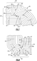
- Figure 6 illustrates a sectioned representation of the airfoil fairing 62 that shows the layered ply architecture of the fiber-reinforced composite 65.
- the profile of the airfoil section 64 is also superimposed on the architecture.
- the illustrated example has three flanges 80, alternate embodiments may have fewer or additional flanges 80.
- FIG 7 shows a closer view of the forward flange 80 of the platform 66 (the aft flange 80 of the platform 66 is of similar architecture), and Figure 8 shows a closer view of the aft flange 80 of the platform 68.
- each of the flanges 80 is formed in part by a portion of the wishbone-shaped fiber layer structure 82 (hereafter "structure 82"). That is, the first arm 82a, the second arm 82b, or the single leg 82c forms at least a portion of the flange 80, while the other of the first arm 82a, the second arm 82b, or the single leg 82c that is not in the flange 80 forms a portion of the platform 66/68.
- structure 82 the wishbone-shaped fiber layer structure 82
- the single leg 82c is upstanding and forms a core portion of the flange 80.
- the single leg 82c extends into the platform 66/68 where the arms 82a/82b split apart and then turn in opposite directions to form portions of the platforms 66/68.
- a filler (i.e., noodle) 89 may be provided at the split.
- the upstanding single leg 82c is thus in the plane of the flange 80 and thereby facilitates stiffening and strengthening of the flange 80.
- the arms 82a/82b provide an integration of the structure 82 into the plane of the platform 66/68, thereby facilitating the anchoring of the flange 80 in the airfoil fairing 62.
- the fiber-reinforced composite 65 additionally includes cavity fiber plies 84 that circumscribe the internal cavity 70 so as to define the full circumferential border thereof.
- the cavity fiber plies 84 are tri-axial braided plies, but may alternatively be another type of woven architecture.
- at least a portion of the cavity fiber plies 84 extend into the platform 66/68 and turn (e.g., at 85) to form a portion of the flange 80.
- the cavity fiber plies 84 that turn into the flange 80 extend along the first arm 82a and the single leg 82c of the structure 82 such that the cavity fiber plies 84 are also upstanding with the single leg 82c.
- At least one of the cavity fiber plies 84 splits from the others and bypasses the flange 80, as represented at 86.
- the first arm 82a of the structure 82 is disposed in the split such that the first arm 82a is interleaved in the platform 66/68 with the cavity fiber plies 84.
- Such an interleaving facilitates the tying together of the layers for added strengthening of the airfoil fairing 62 and anchoring of the structure 82.
- the fiber-reinforced composite 65 additionally includes one or more over-layer plies 87 that wrap around the perimeter of the airfoil section 64.
- the over-layer plies 87 may be of the same architecture (e.g., braid or harness weave) but more typically will be of different architectures.
- one or more over-layer plies 87a are tri-axially braided plies and one or more over-layer plies 87b are harness weave plies (e.g., 8 harness weave).
- the over-layer plies 87 serve to reinforce the airfoil section 64. At least a portion of the over-layer plies 87 also turn and form a portion of the platforms 66/68.
- the flanges 80 may additionally include one or more cover plies 88 that form a portion of the flange 80 and that turn from the flange 80 into the platform 66/68.
- the cover plies serve to further reinforce the flanges 80 and also integrate the flanges with the platforms 66/68.
- the flange 80 may also include one or more filler fiber plies 89 that are interleaved between the cover plies 88.
- the filler fiber plies 89 may be relatively short and extend only in, or mainly only in, the flange 80.
- the filler fiber plies 89 serve for additional reinforcement and increase the thickness of the flange 80.
- the fiber-reinforced composite 65 is not limited to a particular method of fabrication.
- the fiber ply layers are infiltrated with the matrix material for densification.
- ceramic material is infiltrated into the fiber ply layers by vapor deposition (e.g., chemical vapor deposition).
- vapor deposition e.g., chemical vapor deposition
- organic or metal matrices may be provided by melt infiltration.
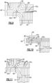
- Figure 9 illustrates an example of a modified architecture for the fiber-reinforced composite 65.
- the cavity fiber plies 84 rather than the cavity fiber plies 84 extending into the platform 66, at least a portion of the cavity fiber plies 84 have ends 84a that abut the arm 82a of the structure 82 in the platform 66.
- the cavity fiber plies 84 are relatively stiff, such an architecture avoids having to turn the cavity fiber plies 84 into the platform 66 and flange 80.
- Figure 10 illustrates another modified architecture of the fiber-reinforced composite 65.
- This architecture is the same as that of Figure 9 except that for the structure 82 the arm 82a is upstanding to form a portion of the flange 80 and the single leg 82c is in the plane of the platform 66.
- the architecture shown in the example in Figure 11 is the same as that of Figure 10 except that filler fiber plies 89 are interleaved with the cover plies 88 and arm 82a of the structure 82.
- Figure 12 illustrates an additional modified architecture of the fiber-reinforced composite 65.
- the inner-most one of the cavity fiber plies 84 turns into the platform 66 and the remaining cavity fiber plies 84 dead-end at the inner-most one of the cavity fiber plies 84.
- the inner-most one of the cavity fiber plies 84 extends in the platform 66 and then terminates at a cavity fiber ply terminal end 84b.
- the end 84b abuts a terminal end 88a of the cover ply 88 to form a butt joint.
- Figure 13 shows another example of the fiber-reinforced composite 65 that is similar to that of Figure 8 .
- several of the cavity fiber plies 84c terminate short of the platform 68, while the remaining cavity fiber plies 84 turn into the platform 68.
- the flanges 80 are of relatively simple geometry that can be readily formed with upstanding fiber plies of the structure 82 and additional fiber plies as necessary for reinforcement and sizing. Furthermore, the structure 82 permits at least a portion of the flange 80 to be integrated into the platform 66/68, thereby providing an anchoring for enhanced flange strength. Moreover, the flange 80 can be formed with any of a variety of different architectures in order to tailor the flange to the particular implementation and, if necessary, provide flanges of different architectures on the same airfoil fairing.
Landscapes
- Engineering & Computer Science (AREA)
- Chemical & Material Sciences (AREA)
- Mechanical Engineering (AREA)
- General Engineering & Computer Science (AREA)
- Ceramic Engineering (AREA)
- Textile Engineering (AREA)
- Materials Engineering (AREA)
- Organic Chemistry (AREA)
- Manufacturing & Machinery (AREA)
- Chemical Kinetics & Catalysis (AREA)
- Structural Engineering (AREA)
- Architecture (AREA)
- Metallurgy (AREA)
- Physics & Mathematics (AREA)
- Fluid Mechanics (AREA)
- Structures Of Non-Positive Displacement Pumps (AREA)
Claims (14)
- Leitschaufel-Bogensegment (60), umfassend:eine Flügelverkleidung (62), die eine Verkleidungsplattform (66, 68) und einen sich davon erstreckenden Flügelabschnitt (64) aufweist, wobei die Verkleidungsplattform (66, 68) eine Gaswegseite (66a, 68a) und eine Nicht-Gaswegseite (66b, 68b) definiert,wobei die Verkleidungsplattform (66, 68) einen Flansch (80) beinhaltet, der von der Nicht-Gaswegseite (66b, 68b) vorsteht,wobei die Flügelverkleidung (62) aus einem faserverstärkten Verbundwerkstoff (65) gebildet ist, der eine querlenkerförmige Faserschichtstruktur (82) beinhaltet, die einen ersten und einen zweiten Zweig (82a, 82b) aufweist, die zusammenlaufen und zu einem einzelnen Teilstück (82c) ineinander übergehen, wobei der ersten und der zweiten Zweig (82a, 82b) aus Faserlagen (84) gebildet sind, die aus einem Netz aus Fasersträngen (83) bestehen, wobei das einzelne Teilstück (82c) Faserstränge (83) aus jeder der Faserlagen (84) des ersten und zweiten Zweigs (82a, 82b) umfasst, undwobei der erste Zweig (82a), der zweite Zweig (82b) oder das einzelne Teilstück (82c) mindestens einen Abschnitt des Flansches (80) bilden,dadurch gekennzeichnet, dass:
die Faserstränge (83) des ersten Zweigs (82a) in dem einzelnen Teilstück (82c) mit den Fasersträngen (83) des zweiten Zweigs (82b) verwoben sind. - Leitschaufel-Bogensegment (60) nach Anspruch 1, wobei das einzelne Teilstück (82c) mindestens einen Abschnitt des Flansches (80) bildet.
- Leitschaufel-Bogensegment (60) nach Anspruch 2, wobei das einzelne Teilstück (82c) in einer Ebene des Flansches (80) aufrecht steht.
- Leitschaufel-Bogensegment (60) nach Anspruch 1, wobei der erste Zweig (82a) mindestens einen Abschnitt des Flansches (80) bildet und sich das einzelne Teilstück (82c) in der Verkleidungsplattform (66, 68) befindet.
- Leitschaufel-Bogensegment (60) nach Anspruch 4, wobei der Flügelabschnitt (64) einen inneren Hohlraum (70) beinhaltet, der faserverstärkte Verbundwerkstoff (65) Hohlraumfaserlagen (84) beinhaltet, die den inneren Hohlraum (70) so umgeben, dass sie einen vollständigen Umfangsrand davon definieren, und mindestens ein Abschnitt der Hohlraumlagen (84) Enden (84a) aufweist, die an das einzelne Teilstück (82c) in der Verkleidungsplattform (66, 68) anliegen.
- Leitschaufel-Bogensegment (60) nach einem der vorhergehenden Ansprüche, wobei der erste und der zweite Zweig (82a, 82b) in der Verkleidungsplattform (66, 68) ineinander übergehen.
- Leitschaufel-Bogensegment (60) nach einem der vorhergehenden Ansprüche, wobei der Flügelabschnitt (64) einen inneren Hohlraum (70) beinhaltet, der faserverstärkte Verbundwerkstoff (65) Hohlraumfaserlagen (84) beinhaltet, die den inneren Hohlraum (70) so umgeben, dass sie einen vollständigen Umfangsrand davon definieren, und sich mindestens ein Abschnitt der Hohlraumlagen (84) in die Verkleidungsplattform (66, 68) erstreckt und abzweigt, um einen Abschnitt des Flansches (80) zu bilden.
- Leitschaufel-Bogensegment (60) nach Anspruch 7, wobei sich mindestens eine der Hohlraumfaserlagen (84) in die Verkleidungsplattform (66, 68) erstreckt und den Flansch (80) umgeht.
- Leitschaufel-Bogensegment (60) nach Anspruch 7 oder 8, wobei der erste Zweig (82a) in der Verkleidungsplattform (66, 68) mit den Hohlraumfaserlagen (84) verschachtelt ist.
- Leitschaufel-Bogensegment (60) nach einem der vorhergehenden Ansprüche, wobei der faserverstärkte Verbundwerkstoff (65) mindestens eine umflochtene Faserlage (87) beinhaltet, die den Flügelabschnitt (64) umgibt und von dem Flügelabschnitt (64) in die Verkleidungsplattform (66, 68) abzweigt.
- Leitschaufel-Bogensegment (60) nach einem der vorhergehenden Ansprüche, wobei der faserverstärkte Verbundwerkstoff (65) ferner mindestens eine Decklage (88) beinhaltet, die einen Abschnitt des Flansches (80) bildet und von dem Flansch (80) in die Verkleidungsplattform (66, 68) abzweigt.
- Leitschaufel-Bogensegment (60) nach einem der vorhergehenden Ansprüche, wobei mindestens eine der Hohlraumfaserlagen (84) kurz vor der Verkleidungsplattform (66, 68) endet.
- Leitschaufel-Bogensegment (60) nach einem der vorhergehenden Ansprüche, wobei der Flügelabschnitt (64) einen inneren Hohlraum (70) beinhaltet und der faserverstärkte Verbundwerkstoff (65) mindestens eine Decklage (88) und Hohlraumfaserlagen (84) beinhaltet, die mindestens eine Decklage (88) einen Abschnitt des Flansches (80) bildet, von dem Flansch (80) in die Verkleidungsplattform (66, 68) abzweigt und an einem Abschlussende (88a) der Decklage endet, die Hohlraumfaserlagen (84) den inneren Hohlraum (70) so umgeben, dass sie einen vollständigen Umfangsrand davon definieren, und sich eine der Hohlraumlagen (84) in die Verkleidungsplattform (66, 68) erstreckt und an einem Abschlussende (84b) der Hohlraumfaserlage endet, das an das Abschlussende (88a) der Decklage anliegt.
- Gasturbinentriebwerk (20), umfassend:einen Verdichterbereich (24);eine Brennkammer (26) in Fluidverbindung mit dem Verdichterbereich (24); undeinen Turbinenbereich (28) in Fluidverbindung mit der Brennkammer (26), wobei der Turbinenbereich (28) Leitschaufel-Bogensegmente (60) aufweist, die um eine Mittelachse (A) des Gasturbinentriebwerks (20) angeordnet sind, wobei jedes der Leitschaufel-Bogensegmente (60) gemäß einem der vorhergehenden Ansprüche ausgebildet ist.
Applications Claiming Priority (1)
| Application Number | Priority Date | Filing Date | Title |
|---|---|---|---|
| US17/182,389 US11346228B1 (en) | 2021-02-23 | 2021-02-23 | Airfoil with flange formed of wishbone-shaped fiber layer structure |
Publications (2)
| Publication Number | Publication Date |
|---|---|
| EP4047185A1 EP4047185A1 (de) | 2022-08-24 |
| EP4047185B1 true EP4047185B1 (de) | 2024-08-14 |
Family
ID=80448348
Family Applications (1)
| Application Number | Title | Priority Date | Filing Date |
|---|---|---|---|
| EP22158268.7A Active EP4047185B1 (de) | 2021-02-23 | 2022-02-23 | Leitschaufel mit flansch aus einer querlenkerförmigen faserschichtstruktur |
Country Status (2)
| Country | Link |
|---|---|
| US (1) | US11346228B1 (de) |
| EP (1) | EP4047185B1 (de) |
Families Citing this family (17)
| Publication number | Priority date | Publication date | Assignee | Title |
|---|---|---|---|---|
| US11591920B2 (en) * | 2020-11-13 | 2023-02-28 | Raytheon Technologies Corporation | Vane arc segment with curved radial flange |
| US11530614B2 (en) * | 2021-02-19 | 2022-12-20 | Raytheon Technologies Corporation | Vane arc segment formed of fiber-reinforced composite |
| US11808176B2 (en) * | 2021-05-04 | 2023-11-07 | Rtx Corporation | CMC vane sealing arrangement |
| US11732589B1 (en) * | 2022-07-15 | 2023-08-22 | Raytheon Technologies Corporation | Airfoil vane multiplet with interleaved fiber plies |
| GB202210820D0 (en) | 2022-07-25 | 2022-09-07 | Rolls Royce Plc | Composite component, method of manufacturing a preform for the component |
| GB202210823D0 (en) | 2022-07-25 | 2022-09-07 | Rolls Royce Plc | Woven structure and method of manufacture |
| US11802487B1 (en) | 2022-08-15 | 2023-10-31 | Rtx Corporation | Gas turbine engine stator vane formed of ceramic matrix composites and having attachment flanges |
| US11913348B1 (en) * | 2022-10-12 | 2024-02-27 | Rtx Corporation | Gas turbine engine vane and spar combination with variable air flow path |
| US11873735B1 (en) * | 2022-11-10 | 2024-01-16 | General Electric Company | Composite component for a gas turbine engine |
| US11920495B1 (en) * | 2023-01-20 | 2024-03-05 | Rtx Corporation | Airfoil with thick wishbone fiber structure |
| US12110807B1 (en) * | 2023-03-14 | 2024-10-08 | Rtx Corporation | Altering structural response of two-piece hollow-vane assembly by changing the cover composition |
| US12392247B2 (en) * | 2023-06-02 | 2025-08-19 | Rtx Corporation | Airfoil with sandwich composite flange |
| US12215603B2 (en) * | 2023-06-23 | 2025-02-04 | Rtx Corporation | CMC airfoil with wishbone shaped fiber layup structure forming portion of platform and root |
| US12292193B2 (en) * | 2023-06-28 | 2025-05-06 | Rtx Corporation | Combustor liner with pattern of voids in CMC fiber ply for cooling channels |
| US12241385B2 (en) * | 2023-07-17 | 2025-03-04 | Rtx Corporation | Wishbone fiber layup structure for airfoil |
| US12326100B1 (en) * | 2024-01-31 | 2025-06-10 | Rtx Corporation | Gas turbine engine component fillets formed of CMC plies |
| FR3162474A1 (fr) * | 2024-05-27 | 2025-11-28 | Safran Aircraft Engines | Aube en materiau composite comprenant une structure fibreuse |
Family Cites Families (12)
| Publication number | Priority date | Publication date | Assignee | Title |
|---|---|---|---|---|
| DE10334342A1 (de) | 2003-07-29 | 2005-02-24 | Mtu Aero Engines Gmbh | Fasergelege und Verfahren zur Herstellung desselben |
| US9062562B2 (en) | 2008-11-28 | 2015-06-23 | Herakles | Composite material turbomachine engine blade or vane, compressor stator segment or turbine nozzle segment incorporating such vanes and method for manufacturing same |
| FR2983519B1 (fr) | 2011-12-01 | 2015-07-24 | Snecma Propulsion Solide | Aube de turbine a pale creuse en materiau composite, turbine ou compresseur ayant un distributeur ou redresseur forme de telles aubes et turbomachine les comprenant |
| US9308708B2 (en) * | 2012-03-23 | 2016-04-12 | General Electric Company | Process for producing ceramic composite components |
| US9664053B2 (en) | 2014-02-12 | 2017-05-30 | Teledyne Scientific & Imaging, Llc | Integral textile structure for 3-D CMC turbine airfoils |
| US10370986B2 (en) * | 2015-07-24 | 2019-08-06 | General Electric Company | Nozzle and nozzle assembly for gas turbine engine |
| FR3080322B1 (fr) * | 2018-04-20 | 2020-03-27 | Safran Aircraft Engines | Aube comprenant une structure en materiau composite et procede de fabrication associe |
| US11041394B2 (en) * | 2018-06-01 | 2021-06-22 | Rolls-Royce Corporation | CMC airfoil joint |
| US20190390555A1 (en) * | 2018-06-22 | 2019-12-26 | United Technologies Corporation | Composite airfoil with cleft in platform |
| US10724387B2 (en) * | 2018-11-08 | 2020-07-28 | Raytheon Technologies Corporation | Continuation of a shear tube through a vane platform for structural support |
| FR3091723B1 (fr) * | 2019-01-15 | 2021-04-02 | Safran Aircraft Engines | Aube ou Pale d'hélice composite pour aéronef intégrant une pièce de conformation |
| US11434177B2 (en) * | 2019-05-13 | 2022-09-06 | Rolls-Royce Plc | Ceramic matrix composite vane with hybrid construction |
-
2021
- 2021-02-23 US US17/182,389 patent/US11346228B1/en active Active
-
2022
- 2022-02-23 EP EP22158268.7A patent/EP4047185B1/de active Active
Also Published As
| Publication number | Publication date |
|---|---|
| EP4047185A1 (de) | 2022-08-24 |
| US11346228B1 (en) | 2022-05-31 |
Similar Documents
| Publication | Publication Date | Title |
|---|---|---|
| EP4047185B1 (de) | Leitschaufel mit flansch aus einer querlenkerförmigen faserschichtstruktur | |
| EP4006307B1 (de) | Schaufelbogensegment mit gekrümmtem radialflansch | |
| US11725527B2 (en) | Vane arc segment formed of fiber-reinforced composite | |
| US11732597B2 (en) | Double box composite seal assembly with insert for gas turbine engine | |
| EP4180633B1 (de) | Gasturbinenschaufel aus faserlagen mit ineinandergreifenden fingern am hinteren ende | |
| EP4283095B1 (de) | Cmc-laminatschaufel mit lagentropfen | |
| EP4030037B1 (de) | Schaufelprofil mit gabelbeinstruktur aus faserverbund | |
| US11359507B2 (en) | Double box composite seal assembly with fiber density arrangement for gas turbine engine | |
| EP4030036A1 (de) | Leitschaufelbogensegment-trägerplattform mit gekrümmtem radialem kanal | |
| EP4053379B1 (de) | Schaufelbogensegment mit holm und stiftverkleidung | |
| EP4494830A1 (de) | Gabelbein-faseraufbaustruktur für schaufelblatt | |
| EP4008703B1 (de) | Keramische komponente | |
| EP4015772B1 (de) | Gasturbinen schaufel mit holm welcher einen eingebettetem plenumdurchgang umfasst | |
| EP4067620B1 (de) | Schaufel mit radial beabstandeten rippen und verschachtelten lappen, und gasturbinentriebwerk | |
| US12000306B2 (en) | Vane arc segment with single-sided platforms | |
| EP4276278B1 (de) | Gasturbinenmotorartikel mit verzweigtem flansch | |
| US12215603B2 (en) | CMC airfoil with wishbone shaped fiber layup structure forming portion of platform and root |
Legal Events
| Date | Code | Title | Description |
|---|---|---|---|
| PUAI | Public reference made under article 153(3) epc to a published international application that has entered the european phase |
Free format text: ORIGINAL CODE: 0009012 |
|
| STAA | Information on the status of an ep patent application or granted ep patent |
Free format text: STATUS: THE APPLICATION HAS BEEN PUBLISHED |
|
| AK | Designated contracting states |
Kind code of ref document: A1 Designated state(s): AL AT BE BG CH CY CZ DE DK EE ES FI FR GB GR HR HU IE IS IT LI LT LU LV MC MK MT NL NO PL PT RO RS SE SI SK SM TR |
|
| STAA | Information on the status of an ep patent application or granted ep patent |
Free format text: STATUS: REQUEST FOR EXAMINATION WAS MADE |
|
| 17P | Request for examination filed |
Effective date: 20230223 |
|
| RBV | Designated contracting states (corrected) |
Designated state(s): AL AT BE BG CH CY CZ DE DK EE ES FI FR GB GR HR HU IE IS IT LI LT LU LV MC MK MT NL NO PL PT RO RS SE SI SK SM TR |
|
| RAP3 | Party data changed (applicant data changed or rights of an application transferred) |
Owner name: RTX CORPORATION |
|
| GRAP | Despatch of communication of intention to grant a patent |
Free format text: ORIGINAL CODE: EPIDOSNIGR1 |
|
| STAA | Information on the status of an ep patent application or granted ep patent |
Free format text: STATUS: GRANT OF PATENT IS INTENDED |
|
| INTG | Intention to grant announced |
Effective date: 20240304 |
|
| GRAS | Grant fee paid |
Free format text: ORIGINAL CODE: EPIDOSNIGR3 |
|
| GRAA | (expected) grant |
Free format text: ORIGINAL CODE: 0009210 |
|
| STAA | Information on the status of an ep patent application or granted ep patent |
Free format text: STATUS: THE PATENT HAS BEEN GRANTED |
|
| AK | Designated contracting states |
Kind code of ref document: B1 Designated state(s): AL AT BE BG CH CY CZ DE DK EE ES FI FR GB GR HR HU IE IS IT LI LT LU LV MC MK MT NL NO PL PT RO RS SE SI SK SM TR |
|
| REG | Reference to a national code |
Ref country code: GB Ref legal event code: FG4D |
|
| REG | Reference to a national code |
Ref country code: CH Ref legal event code: EP |
|
| REG | Reference to a national code |
Ref country code: DE Ref legal event code: R096 Ref document number: 602022005240 Country of ref document: DE |
|
| REG | Reference to a national code |
Ref country code: IE Ref legal event code: FG4D |
|
| REG | Reference to a national code |
Ref country code: LT Ref legal event code: MG9D |
|
| REG | Reference to a national code |
Ref country code: NL Ref legal event code: MP Effective date: 20240814 |
|
| PG25 | Lapsed in a contracting state [announced via postgrant information from national office to epo] |
Ref country code: NO Free format text: LAPSE BECAUSE OF FAILURE TO SUBMIT A TRANSLATION OF THE DESCRIPTION OR TO PAY THE FEE WITHIN THE PRESCRIBED TIME-LIMIT Effective date: 20241114 |
|
| REG | Reference to a national code |
Ref country code: AT Ref legal event code: MK05 Ref document number: 1713472 Country of ref document: AT Kind code of ref document: T Effective date: 20240814 |
|
| PG25 | Lapsed in a contracting state [announced via postgrant information from national office to epo] |
Ref country code: NL Free format text: LAPSE BECAUSE OF FAILURE TO SUBMIT A TRANSLATION OF THE DESCRIPTION OR TO PAY THE FEE WITHIN THE PRESCRIBED TIME-LIMIT Effective date: 20240814 Ref country code: PT Free format text: LAPSE BECAUSE OF FAILURE TO SUBMIT A TRANSLATION OF THE DESCRIPTION OR TO PAY THE FEE WITHIN THE PRESCRIBED TIME-LIMIT Effective date: 20241216 Ref country code: PL Free format text: LAPSE BECAUSE OF FAILURE TO SUBMIT A TRANSLATION OF THE DESCRIPTION OR TO PAY THE FEE WITHIN THE PRESCRIBED TIME-LIMIT Effective date: 20240814 Ref country code: GR Free format text: LAPSE BECAUSE OF FAILURE TO SUBMIT A TRANSLATION OF THE DESCRIPTION OR TO PAY THE FEE WITHIN THE PRESCRIBED TIME-LIMIT Effective date: 20241115 Ref country code: FI Free format text: LAPSE BECAUSE OF FAILURE TO SUBMIT A TRANSLATION OF THE DESCRIPTION OR TO PAY THE FEE WITHIN THE PRESCRIBED TIME-LIMIT Effective date: 20240814 |
|
| PG25 | Lapsed in a contracting state [announced via postgrant information from national office to epo] |
Ref country code: BG Free format text: LAPSE BECAUSE OF FAILURE TO SUBMIT A TRANSLATION OF THE DESCRIPTION OR TO PAY THE FEE WITHIN THE PRESCRIBED TIME-LIMIT Effective date: 20240814 |
|
| PG25 | Lapsed in a contracting state [announced via postgrant information from national office to epo] |
Ref country code: LV Free format text: LAPSE BECAUSE OF FAILURE TO SUBMIT A TRANSLATION OF THE DESCRIPTION OR TO PAY THE FEE WITHIN THE PRESCRIBED TIME-LIMIT Effective date: 20240814 |
|
| PG25 | Lapsed in a contracting state [announced via postgrant information from national office to epo] |
Ref country code: IS Free format text: LAPSE BECAUSE OF FAILURE TO SUBMIT A TRANSLATION OF THE DESCRIPTION OR TO PAY THE FEE WITHIN THE PRESCRIBED TIME-LIMIT Effective date: 20241214 Ref country code: AT Free format text: LAPSE BECAUSE OF FAILURE TO SUBMIT A TRANSLATION OF THE DESCRIPTION OR TO PAY THE FEE WITHIN THE PRESCRIBED TIME-LIMIT Effective date: 20240814 |
|
| PG25 | Lapsed in a contracting state [announced via postgrant information from national office to epo] |
Ref country code: HR Free format text: LAPSE BECAUSE OF FAILURE TO SUBMIT A TRANSLATION OF THE DESCRIPTION OR TO PAY THE FEE WITHIN THE PRESCRIBED TIME-LIMIT Effective date: 20240814 |
|
| PG25 | Lapsed in a contracting state [announced via postgrant information from national office to epo] |
Ref country code: RS Free format text: LAPSE BECAUSE OF FAILURE TO SUBMIT A TRANSLATION OF THE DESCRIPTION OR TO PAY THE FEE WITHIN THE PRESCRIBED TIME-LIMIT Effective date: 20241114 Ref country code: ES Free format text: LAPSE BECAUSE OF FAILURE TO SUBMIT A TRANSLATION OF THE DESCRIPTION OR TO PAY THE FEE WITHIN THE PRESCRIBED TIME-LIMIT Effective date: 20240814 |
|
| PG25 | Lapsed in a contracting state [announced via postgrant information from national office to epo] |
Ref country code: RS Free format text: LAPSE BECAUSE OF FAILURE TO SUBMIT A TRANSLATION OF THE DESCRIPTION OR TO PAY THE FEE WITHIN THE PRESCRIBED TIME-LIMIT Effective date: 20241114 Ref country code: PT Free format text: LAPSE BECAUSE OF FAILURE TO SUBMIT A TRANSLATION OF THE DESCRIPTION OR TO PAY THE FEE WITHIN THE PRESCRIBED TIME-LIMIT Effective date: 20241216 Ref country code: PL Free format text: LAPSE BECAUSE OF FAILURE TO SUBMIT A TRANSLATION OF THE DESCRIPTION OR TO PAY THE FEE WITHIN THE PRESCRIBED TIME-LIMIT Effective date: 20240814 Ref country code: NO Free format text: LAPSE BECAUSE OF FAILURE TO SUBMIT A TRANSLATION OF THE DESCRIPTION OR TO PAY THE FEE WITHIN THE PRESCRIBED TIME-LIMIT Effective date: 20241114 Ref country code: NL Free format text: LAPSE BECAUSE OF FAILURE TO SUBMIT A TRANSLATION OF THE DESCRIPTION OR TO PAY THE FEE WITHIN THE PRESCRIBED TIME-LIMIT Effective date: 20240814 Ref country code: LV Free format text: LAPSE BECAUSE OF FAILURE TO SUBMIT A TRANSLATION OF THE DESCRIPTION OR TO PAY THE FEE WITHIN THE PRESCRIBED TIME-LIMIT Effective date: 20240814 Ref country code: IS Free format text: LAPSE BECAUSE OF FAILURE TO SUBMIT A TRANSLATION OF THE DESCRIPTION OR TO PAY THE FEE WITHIN THE PRESCRIBED TIME-LIMIT Effective date: 20241214 Ref country code: HR Free format text: LAPSE BECAUSE OF FAILURE TO SUBMIT A TRANSLATION OF THE DESCRIPTION OR TO PAY THE FEE WITHIN THE PRESCRIBED TIME-LIMIT Effective date: 20240814 Ref country code: GR Free format text: LAPSE BECAUSE OF FAILURE TO SUBMIT A TRANSLATION OF THE DESCRIPTION OR TO PAY THE FEE WITHIN THE PRESCRIBED TIME-LIMIT Effective date: 20241115 Ref country code: FI Free format text: LAPSE BECAUSE OF FAILURE TO SUBMIT A TRANSLATION OF THE DESCRIPTION OR TO PAY THE FEE WITHIN THE PRESCRIBED TIME-LIMIT Effective date: 20240814 Ref country code: ES Free format text: LAPSE BECAUSE OF FAILURE TO SUBMIT A TRANSLATION OF THE DESCRIPTION OR TO PAY THE FEE WITHIN THE PRESCRIBED TIME-LIMIT Effective date: 20240814 Ref country code: BG Free format text: LAPSE BECAUSE OF FAILURE TO SUBMIT A TRANSLATION OF THE DESCRIPTION OR TO PAY THE FEE WITHIN THE PRESCRIBED TIME-LIMIT Effective date: 20240814 Ref country code: AT Free format text: LAPSE BECAUSE OF FAILURE TO SUBMIT A TRANSLATION OF THE DESCRIPTION OR TO PAY THE FEE WITHIN THE PRESCRIBED TIME-LIMIT Effective date: 20240814 |
|
| PGFP | Annual fee paid to national office [announced via postgrant information from national office to epo] |
Ref country code: DE Payment date: 20250122 Year of fee payment: 4 |
|
| PG25 | Lapsed in a contracting state [announced via postgrant information from national office to epo] |
Ref country code: DK Free format text: LAPSE BECAUSE OF FAILURE TO SUBMIT A TRANSLATION OF THE DESCRIPTION OR TO PAY THE FEE WITHIN THE PRESCRIBED TIME-LIMIT Effective date: 20240814 Ref country code: SM Free format text: LAPSE BECAUSE OF FAILURE TO SUBMIT A TRANSLATION OF THE DESCRIPTION OR TO PAY THE FEE WITHIN THE PRESCRIBED TIME-LIMIT Effective date: 20240814 Ref country code: RO Free format text: LAPSE BECAUSE OF FAILURE TO SUBMIT A TRANSLATION OF THE DESCRIPTION OR TO PAY THE FEE WITHIN THE PRESCRIBED TIME-LIMIT Effective date: 20240814 |
|
| PG25 | Lapsed in a contracting state [announced via postgrant information from national office to epo] |
Ref country code: EE Free format text: LAPSE BECAUSE OF FAILURE TO SUBMIT A TRANSLATION OF THE DESCRIPTION OR TO PAY THE FEE WITHIN THE PRESCRIBED TIME-LIMIT Effective date: 20240814 |
|
| PG25 | Lapsed in a contracting state [announced via postgrant information from national office to epo] |
Ref country code: CZ Free format text: LAPSE BECAUSE OF FAILURE TO SUBMIT A TRANSLATION OF THE DESCRIPTION OR TO PAY THE FEE WITHIN THE PRESCRIBED TIME-LIMIT Effective date: 20240814 |
|
| PGFP | Annual fee paid to national office [announced via postgrant information from national office to epo] |
Ref country code: FR Payment date: 20250121 Year of fee payment: 4 |
|
| PG25 | Lapsed in a contracting state [announced via postgrant information from national office to epo] |
Ref country code: SK Free format text: LAPSE BECAUSE OF FAILURE TO SUBMIT A TRANSLATION OF THE DESCRIPTION OR TO PAY THE FEE WITHIN THE PRESCRIBED TIME-LIMIT Effective date: 20240814 Ref country code: IT Free format text: LAPSE BECAUSE OF FAILURE TO SUBMIT A TRANSLATION OF THE DESCRIPTION OR TO PAY THE FEE WITHIN THE PRESCRIBED TIME-LIMIT Effective date: 20240814 |
|
| REG | Reference to a national code |
Ref country code: DE Ref legal event code: R097 Ref document number: 602022005240 Country of ref document: DE |
|
| PLBE | No opposition filed within time limit |
Free format text: ORIGINAL CODE: 0009261 |
|
| STAA | Information on the status of an ep patent application or granted ep patent |
Free format text: STATUS: NO OPPOSITION FILED WITHIN TIME LIMIT |
|
| 26N | No opposition filed |
Effective date: 20250515 |
|
| PG25 | Lapsed in a contracting state [announced via postgrant information from national office to epo] |
Ref country code: SE Free format text: LAPSE BECAUSE OF FAILURE TO SUBMIT A TRANSLATION OF THE DESCRIPTION OR TO PAY THE FEE WITHIN THE PRESCRIBED TIME-LIMIT Effective date: 20240814 |
|
| PG25 | Lapsed in a contracting state [announced via postgrant information from national office to epo] |
Ref country code: MC Free format text: LAPSE BECAUSE OF FAILURE TO SUBMIT A TRANSLATION OF THE DESCRIPTION OR TO PAY THE FEE WITHIN THE PRESCRIBED TIME-LIMIT Effective date: 20240814 |
|
| REG | Reference to a national code |
Ref country code: CH Ref legal event code: PL |
|
| PG25 | Lapsed in a contracting state [announced via postgrant information from national office to epo] |
Ref country code: LU Free format text: LAPSE BECAUSE OF NON-PAYMENT OF DUE FEES Effective date: 20250223 |
|
| PG25 | Lapsed in a contracting state [announced via postgrant information from national office to epo] |
Ref country code: CH Free format text: LAPSE BECAUSE OF NON-PAYMENT OF DUE FEES Effective date: 20250228 |
|
| REG | Reference to a national code |
Ref country code: BE Ref legal event code: MM Effective date: 20250228 |
|
| PG25 | Lapsed in a contracting state [announced via postgrant information from national office to epo] |
Ref country code: BE Free format text: LAPSE BECAUSE OF NON-PAYMENT OF DUE FEES Effective date: 20250228 |
|
| PG25 | Lapsed in a contracting state [announced via postgrant information from national office to epo] |
Ref country code: IE Free format text: LAPSE BECAUSE OF NON-PAYMENT OF DUE FEES Effective date: 20250223 |