EP4046948A1 - Guide and carriage for application with a device for the blocking of the wheel of a truck on a lane in front of a loading and unloading platform - Google Patents
Guide and carriage for application with a device for the blocking of the wheel of a truck on a lane in front of a loading and unloading platform Download PDFInfo
- Publication number
- EP4046948A1 EP4046948A1 EP22156248.1A EP22156248A EP4046948A1 EP 4046948 A1 EP4046948 A1 EP 4046948A1 EP 22156248 A EP22156248 A EP 22156248A EP 4046948 A1 EP4046948 A1 EP 4046948A1
- Authority
- EP
- European Patent Office
- Prior art keywords
- carriage
- guide
- housing part
- rolls
- guide housing
- Prior art date
- Legal status (The legal status is an assumption and is not a legal conclusion. Google has not performed a legal analysis and makes no representation as to the accuracy of the status listed.)
- Pending
Links
- 230000000903 blocking effect Effects 0.000 title claims abstract description 7
- 238000010276 construction Methods 0.000 claims description 3
- 239000000463 material Substances 0.000 claims description 3
- 230000006835 compression Effects 0.000 description 1
- 238000007906 compression Methods 0.000 description 1
- 230000007613 environmental effect Effects 0.000 description 1
- 239000002699 waste material Substances 0.000 description 1
Images




Classifications
-
- B—PERFORMING OPERATIONS; TRANSPORTING
- B65—CONVEYING; PACKING; STORING; HANDLING THIN OR FILAMENTARY MATERIAL
- B65G—TRANSPORT OR STORAGE DEVICES, e.g. CONVEYORS FOR LOADING OR TIPPING, SHOP CONVEYOR SYSTEMS OR PNEUMATIC TUBE CONVEYORS
- B65G69/00—Auxiliary measures taken, or devices used, in connection with loading or unloading
- B65G69/003—Restraining movement of a vehicle at a loading station using means not being part of the vehicle
- B65G69/005—Restraining movement of a vehicle at a loading station using means not being part of the vehicle the means engaging at least one wheel of the vehicle
-
- F—MECHANICAL ENGINEERING; LIGHTING; HEATING; WEAPONS; BLASTING
- F16—ENGINEERING ELEMENTS AND UNITS; GENERAL MEASURES FOR PRODUCING AND MAINTAINING EFFECTIVE FUNCTIONING OF MACHINES OR INSTALLATIONS; THERMAL INSULATION IN GENERAL
- F16C—SHAFTS; FLEXIBLE SHAFTS; ELEMENTS OR CRANKSHAFT MECHANISMS; ROTARY BODIES OTHER THAN GEARING ELEMENTS; BEARINGS
- F16C29/00—Bearings for parts moving only linearly
- F16C29/005—Guide rails or tracks for a linear bearing, i.e. adapted for movement of a carriage or bearing body there along
-
- F—MECHANICAL ENGINEERING; LIGHTING; HEATING; WEAPONS; BLASTING
- F16—ENGINEERING ELEMENTS AND UNITS; GENERAL MEASURES FOR PRODUCING AND MAINTAINING EFFECTIVE FUNCTIONING OF MACHINES OR INSTALLATIONS; THERMAL INSULATION IN GENERAL
- F16C—SHAFTS; FLEXIBLE SHAFTS; ELEMENTS OR CRANKSHAFT MECHANISMS; ROTARY BODIES OTHER THAN GEARING ELEMENTS; BEARINGS
- F16C29/00—Bearings for parts moving only linearly
- F16C29/02—Sliding-contact bearings
-
- F—MECHANICAL ENGINEERING; LIGHTING; HEATING; WEAPONS; BLASTING
- F16—ENGINEERING ELEMENTS AND UNITS; GENERAL MEASURES FOR PRODUCING AND MAINTAINING EFFECTIVE FUNCTIONING OF MACHINES OR INSTALLATIONS; THERMAL INSULATION IN GENERAL
- F16C—SHAFTS; FLEXIBLE SHAFTS; ELEMENTS OR CRANKSHAFT MECHANISMS; ROTARY BODIES OTHER THAN GEARING ELEMENTS; BEARINGS
- F16C2326/00—Articles relating to transporting
- F16C2326/58—Conveyor systems, e.g. rollers or bearings therefor
Definitions
- the present invention relates to guide extending from a road side to a façade side, and a carriage provided with a locking arm with rolls or such like, by means of which the carriage is movable along one or more lines provided on the guide, for application with a device for the blocking of the wheel of a truck on a lane in front of a loading and unloading platform.
- the European application EP-A- 3 028 966 describes a guide and carriage that is formed such that the guide on the top and sides more or less is enclosed by the housing of the carriage.
- the present invention aims to provide an improved guide and carriage.
- the guide and carriage for application with a device for the blocking of the wheel of a truck on a lane in front of a loading and unloading platform thereto is characterized, in that the carriage, as seen from the roadside towards the façade side, comprises a left carriage housing part and a right carriage housing part, and whereby the guide, as seen from the road side towards the façade side, comprises a left guide housing part and a right guide housing part, and whereby the left carriage housing part at least partly is taken up within the left guide housing part or is enclosed thereby and/or whereby the right carriage housing part at least partly is taken up within the right guide housing part or is enclosed thereby.
- the left carriage housing part has an outer side having a shape
- the left guide housing part has an inner side having a shape, that are adapted to each other, such, that the left carriage housing part is taken up more or less fitting or with some interspace within the left guide housing part or is thereby enclosed.
- the right carriage housing part has an outer side having a shape
- the right guide housing part has an inner side having a shape, that are adapted to each other, such that the right carriage housing part is taken up more or less fitting or with some interspace within the right guide housing part or is thereby enclosed.
- the left guide housing part is provided with a path or track and the left carriage housing part is provided with one or more rolls, and by means of which the carriage is movable over the guide, and/or whereby the right guide housing part is provided with a path or track and the right carriage housing part is provided with one or more rolls, and by means of which the carriage is movable over the guide.
- a track is formed on the upper side of a lower part of the left guide housing part and/or a track is formed on the upper side of a lower part of the right guide housing part, and over which the rolls move and by which the carriage is movable over the guide.
- a guide housing part or both the guide housing parts have the shape of a lying U-section, the legs of which are directed towards the middle of the carriage, while according to another characteristic, a carriage housing part or both the carriage housing parts have the shape substantially of a lying U-section, the legs of which are directed towards the middle of the carriage.
- FIG 1 a device 1 for the blocking of the wheel 2 of a truck 3 with a rear beam 38 on a lane 4 in front of a loading and unloading platform 5.
- two guides 6 extending from the road side 7 to the façade side 8.
- a carriage 10 that is provided with a locking arm 9.
- the carriage is provided with rolls 11.
- the carriage 10 comprises, as seen from the road side 7 towards the façade side 8, a left carriage housing part 12 and a right carriage housing part 13.
- the guide 6, as seen from the road side 7 towards the façade side 8 comprises a left guide housing part 14 and a right guide housing part 15.
- both the guide housing parts 14, 15 have the shape of a lying U-section 16, 17, whereby the legs 18, 19 of the left guide housing part 14 and the legs 20, 21 of the right guide housing part 15 are directed towards the middle 22 of the carriage.
- both the carriage housing parts 12, 13 also have the shape of a lying U-section 23, 24, whereby the legs 25, 26 of the left carriage housing part 12 and the legs 27, 28 of the right carriage housing part 13 are directed towards the middle 22 of the carriage.
- the distance between the legs 18, 19 of the left guide housing part 14 is larger than that between the legs 25, 26 of the left carriage housing part 12, and the distance between the legs 20, 21 of the right guide housing part 15 is larger than that between the legs 27, 28 of the right carriage housing part 13.
- the left carriage housing part 12 with the legs 25, 26 is substantially taken up within the legs 18, 19 of the left guide housing part 14 or is thereby enclosed.
- the right carriage housing part 13 with the legs 27, 28 is substantially taken up within the legs 20, 21 of the left guide housing part 15.
- the carriage housing parts and the guide housing parts self-evidently may also have another shape. Important is that the shapes of the parts are more or less the same, such that the carriage housing parts can be taken up more or less fitting, or with some interspace, within the guide housing parts.
- the carriage housing parts 12, 13 at the outer side 29 are provided with sliding strips in the shape of strips of material 30.
- a carriage housing part 12, 13 can rest against the inner side 31 of a guide housing part 14, 15 or can slide or glide there along, as will be explained hereafter.
- the lower legs 19, 21 of the guide housing parts 14, 15 are provided with a path or track 32, 33.
- the carriage 10 is provided with two axles 34, at both the outer ends of which the rolls 11 are provided.
- the rolls 11 make contact with the track 32, 33 through openings 35 that are provided in the lower legs 26, 28 of the carriage housing parts 12, 13. In this way the carriage 10 with the rolls 11 moves over the tracks 32, 33 along the guide 6.
- the axles 34 are mounted to the carriage 10 by means of a spring construction 36.
- the spring construction 36 is designed such, that this carries the self-weight of the carriage 10, at minimal compression.
- the axle 34 springs in, and the rolls 11 can move upwards through the openings 35 in the lower legs 26, 28, or the carriage downwards, see figure 5 and figure 6 .
- the carriage 10 can directly, without further loading or overloading of the rolls 11, be pushed downwards by the force exerted by the tire 2 of the truck 3 onto the locking arm 9 and onto the carriage 10.
- Under the pressure of the locking arm 9 the carriage housing parts 12, 13 can lean against the inner side 31 ( figure 5 ) of the guide housing parts 14, 15 without the rolls 11 being further loaded or overloaded.
- the carriage housing parts 12, 13 at the outer side 29 are provided with sliding strips 30 in the form of strips of material applied to among other the upper legs 25, 27, the lower legs 26, 28 and the backs 37. These sliding strips 30 can transfer all the forces of the carriage to the guide 6. By means of this the unlocking of the locking system under high pressure is guaranteed.
- the lower legs 19, 21 of the guide housing parts 14, 15 extend inclined downwards in the direction towards the middle 22 of the carriage. By this it is achieved that rainwater can run out of the guide to waste.
- the legs of the guide housing parts 14, 15 can be provided with openings through which dirt can be removed.
- the locking arm 9 has been mounted relatively low to the truck 10. As, because of this, the locking arm 9 contacts the wheel 2 of the truck at a lower point, the locking arm suffers a larger load by this wheel. With the guide and carriage according to the invention this load can be met optimally.
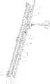
- FIG 2 and in figure 8 is shown the carriage 10 on the guide 6.
- the guide 6, at the side along which the truck 3 drives in and out (in the example of an embodiment shown that is, as seen from the roadside 7 towards the façade side 8, the left side), is designed as a low profile, as a result of which no conflict with the rear beam 38 of the truck 3 that is driving in and out occurs (see also figure 4 ).
- the carriage has been formed such, see figure 8 , that if the locking arm is in the not-locking position, there is a free space 39 or zone between the plane of the wheel guide profile 40, extending parallel to the lane, and the part of the truck 3 standing nearest the lane which protrudes above the guide 6. Also by this the chance of a conflict of the carriage with the rear beam 38 of the truck that is driving in and out is minimized.
Landscapes
- Engineering & Computer Science (AREA)
- General Engineering & Computer Science (AREA)
- Mechanical Engineering (AREA)
- Handcart (AREA)
Abstract
Description
- Guide and carriage for application with a device for the blocking of the wheel of a truck on a lane in front of a loading and unloading platform.
- The present invention relates to guide extending from a road side to a façade side, and a carriage provided with a locking arm with rolls or such like, by means of which the carriage is movable along one or more lines provided on the guide, for application with a device for the blocking of the wheel of a truck on a lane in front of a loading and unloading platform.
- Such a guide and carriage are known.
- The European application
EP-A- 3 028 966 describes a guide and carriage that is formed such that the guide on the top and sides more or less is enclosed by the housing of the carriage. - The American application
US 2011/0162916 A1 describes a guide formed by a support beam placed on legs. On the support beam a flat top plate is welded. By means of rolls the carriage rests on the flat top plate and with rolls underneath the top plate that lie against the support beam. Also with this guide and carriage the guide on the top and sides is more or less enclosed by the housing of the carriage. - The American application
US 2010/0170754 A describes a guide with two parallel U-sections the flanges of which are turned away from each other, and whereby the carriage via the guide rides on rolls that are taken up within the flanges of the U-sections. - The present invention aims to provide an improved guide and carriage.
- The guide and carriage for application with a device for the blocking of the wheel of a truck on a lane in front of a loading and unloading platform thereto is characterized, in that the carriage, as seen from the roadside towards the façade side, comprises a left carriage housing part and a right carriage housing part, and whereby the guide, as seen from the road side towards the façade side, comprises a left guide housing part and a right guide housing part, and whereby the left carriage housing part at least partly is taken up within the left guide housing part or is enclosed thereby and/or whereby the right carriage housing part at least partly is taken up within the right guide housing part or is enclosed thereby.
- According to a characteristic of the guide and carriage according to the invention, the left carriage housing part has an outer side having a shape, and the left guide housing part has an inner side having a shape, that are adapted to each other, such, that the left carriage housing part is taken up more or less fitting or with some interspace within the left guide housing part or is thereby enclosed.
- According to a further characteristic of the guide and carriage according to the invention the right carriage housing part has an outer side having a shape, and the right guide housing part has an inner side having a shape, that are adapted to each other, such that the right carriage housing part is taken up more or less fitting or with some interspace within the right guide housing part or is thereby enclosed.
- According to another characteristic of the guide and carriage according to the invention the left guide housing part is provided with a path or track and the left carriage housing part is provided with one or more rolls, and by means of which the carriage is movable over the guide, and/or whereby the right guide housing part is provided with a path or track and the right carriage housing part is provided with one or more rolls, and by means of which the carriage is movable over the guide.
- According to a further characteristic of the guide and carriage according to the invention a track is formed on the upper side of a lower part of the left guide housing part and/or a track is formed on the upper side of a lower part of the right guide housing part, and over which the rolls move and by which the carriage is movable over the guide.
- According to a further characteristic of the guide and carriage according to the invention, a guide housing part or both the guide housing parts have the shape of a lying U-section, the legs of which are directed towards the middle of the carriage, while according to another characteristic, a carriage housing part or both the carriage housing parts have the shape substantially of a lying U-section, the legs of which are directed towards the middle of the carriage.
- Further characteristics and particulars of the guide and carriage according to the invention will be explained with reference to the drawings of an example of an embodiment.
-
Figure 1 shows a perspective view of a loading and unloading platform with shown thereon two lanes with a guide and carriage according to the invention. -
Figure 2 shows a perspective view of an example of an embodiment of a guide and carriage according to the invention. -
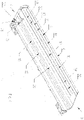
Figure 3 shows a perspective view of a carriage according to the invention. -
Figure 4 shows a perspective view of a part of a guide according to the invention. -
Figure 5 shows, as seen from the road side towards the façade side, a front view in cross section of a part of a guide with carriage according to the invention. -
Figure 6 shows a perspective bottom view of a carriage according to the invention. -
Figure 7 shows, as seen from the road side towards the façade side, a front view in cross section of a part of a carriage according to the invention. -
Figure 8 shows, as seen from the road side towards the façade side, a front view of the carriage on the guide. - In
figure 1 is shown a device 1 for the blocking of thewheel 2 of atruck 3 with arear beam 38 on a lane 4 in front of a loading andunloading platform 5. There are shown twoguides 6 extending from theroad side 7 to thefaçade side 8. On eachguide 6 there is shown acarriage 10 that is provided with alocking arm 9. As shown in thefigures 3 ,5 and6 the carriage is provided withrolls 11. - As can be seen in the
figures 3 ,5 and6 thecarriage 10 comprises, as seen from theroad side 7 towards thefaçade side 8, a leftcarriage housing part 12 and a rightcarriage housing part 13. As can be seen in thefigures 2 ,4 and5 theguide 6, as seen from theroad side 7 towards thefaçade side 8, comprises a leftguide housing part 14 and a rightguide housing part 15. In the example of an embodiment shown both theguide housing parts U-section legs guide housing part 14 and thelegs guide housing part 15 are directed towards the middle 22 of the carriage. - Further, in the example of an embodiment shown both the
carriage housing parts U-section legs carriage housing part 12 and thelegs carriage housing part 13 are directed towards the middle 22 of the carriage. - As can be seen the distance between the
legs guide housing part 14 is larger than that between thelegs carriage housing part 12, and the distance between thelegs guide housing part 15 is larger than that between thelegs carriage housing part 13. - As can be seen in the figures the left
carriage housing part 12 with thelegs legs guide housing part 14 or is thereby enclosed. In the same way the rightcarriage housing part 13 with thelegs legs guide housing part 15. - Instead of an U-section shape the carriage housing parts and the guide housing parts self-evidently may also have another shape. Important is that the shapes of the parts are more or less the same, such that the carriage housing parts can be taken up more or less fitting, or with some interspace, within the guide housing parts.
- As can be seen in the
figures 3 ,5 and6 thecarriage housing parts outer side 29 are provided with sliding strips in the shape of strips ofmaterial 30. By means of this acarriage housing part inner side 31 of aguide housing part - As can be seen in
figure 4 and5 , thelower legs guide housing parts track figures 6 and7 it can be seen that thecarriage 10 is provided with twoaxles 34, at both the outer ends of which therolls 11 are provided. As can be seen infigure 5 , therolls 11 make contact with thetrack openings 35 that are provided in thelower legs carriage housing parts carriage 10 with therolls 11 moves over thetracks guide 6. - As can further be seen in
figure 7 , theaxles 34 are mounted to thecarriage 10 by means of aspring construction 36. Thespring construction 36 is designed such, that this carries the self-weight of thecarriage 10, at minimal compression. When thelocking arm 9 is loaded by thetruck 3, and thereby thecarriage 10 is loaded, theaxle 34 springs in, and therolls 11 can move upwards through theopenings 35 in thelower legs figure 5 andfigure 6 . Thereby thecarriage 10 can directly, without further loading or overloading of therolls 11, be pushed downwards by the force exerted by thetire 2 of thetruck 3 onto the lockingarm 9 and onto thecarriage 10. Under the pressure of thelocking arm 9 thecarriage housing parts figure 5 ) of theguide housing parts rolls 11 being further loaded or overloaded. - In order to still be able, when unlocking the carriage under a high load, when the rolls have sprung in, to slide the carriage, the
carriage housing parts outer side 29 are provided with slidingstrips 30 in the form of strips of material applied to among other theupper legs lower legs backs 37. These slidingstrips 30 can transfer all the forces of the carriage to theguide 6. By means of this the unlocking of the locking system under high pressure is guaranteed. - As can be seen in
figure 5 thelower legs guide housing parts guide housing parts - Present safety and environmental regulations demand with regard to the bodywork and the rear beam of trucks that these are positioned at less height from the road surface. Like this for instance the
aerodynamic side cover 41, that covers also a part of the wheels, as shown infigure 1 . The guide and the carriage according to the invention are adapted to this. - The locking
arm 9 has been mounted relatively low to thetruck 10. As, because of this, the lockingarm 9 contacts thewheel 2 of the truck at a lower point, the locking arm suffers a larger load by this wheel. With the guide and carriage according to the invention this load can be met optimally. - In
figure 2 and infigure 8 is shown thecarriage 10 on theguide 6. Theguide 6, at the side along which thetruck 3 drives in and out (in the example of an embodiment shown that is, as seen from theroadside 7 towards thefaçade side 8, the left side), is designed as a low profile, as a result of which no conflict with therear beam 38 of thetruck 3 that is driving in and out occurs (see alsofigure 4 ). Further, the carriage has been formed such, seefigure 8 , that if the locking arm is in the not-locking position, there is afree space 39 or zone between the plane of thewheel guide profile 40, extending parallel to the lane, and the part of thetruck 3 standing nearest the lane which protrudes above theguide 6. Also by this the chance of a conflict of the carriage with therear beam 38 of the truck that is driving in and out is minimized.
Claims (16)
- Guide extending from a road side to a façade side, and a carriage provided with a locking arm with rolls or such like, by means of which the carriage is movable along one or more paths or tracks provided on the guide, for application with a device for the blocking of the wheel of a truck on a lane in front of a loading and unloading platform, characterized in that the carriage, as seen from the roadside towards the façade side, comprises a left carriage housing part and a right carriage housing part, and whereby the guide, as seen from the road side towards the façade side comprises a left guide housing part and a right guide housing part, and whereby the left carriage housing part at least partly is taken up within the left guide housing part or is enclosed thereby and/or whereby the right carriage housing part at least partly is taken up within the right guide housing part or is enclosed thereby.
- Guide and carriage according to claim 1, characterized in that the left carriage housing part has an outer side having a shape, and the left guide housing part has an inner side having a shape, that are adapted to each other, such the left carriage housing part is taken up more or less fitting or with some interspace within the left guide housing part or is thereby enclosed.
- Guide and carriage according to claim 1 or 2, characterized in that the right carriage housing part has an outer side having a shape, and the right guide housing part has an inner side having a shape, that are adapted to each other, such the right carriage housing part is taken up more or less fitting or with some interspace within the right guide housing part or is thereby enclosed.
- Guide and carriage according to one of the preceding claims, characterized in that the left guide housing part is provided with a track and the left carriage housing part is provided with one or more rolls, and by means of which the carriage is movable over the guide, and/or whereby the right guide housing part is provided with a track and the right carriage housing part is provided with one or more rolls, and by means of which the carriage is movable over the guide.
- Guide and carriage according to claim 4, characterized in that a track is formed on the upper side of a lower part of the left guide housing part and/or a track is formed on the upper side of a lower part of the right guide housing part.
- Guide and carriage according to claim 5, characterized in that the upper side of the lower part of one or that of both guide housing parts, as seen in the direction towards the middle of the carriage, has a downwards inclined path.
- Guide and carriage according to one of the preceding claims, characterized in that a guide housing part or both the guide housing parts have the shape substantially of a lying U-section, the legs of which are directed towards the middle of the carriage.
- Guide and carriage according to one of the preceding claims, characterized in that a carriage housing part or both the carriage housing parts have the shape substantially of a lying U-section, the legs of which are directed towards the middle of the carriage.
- Guide and carriage according to claim 8, characterized in that the distance between the legs of the left guide housing part is larger than that between the legs of the left carriage housing part.
- Guide and carriage according to claim 8 or 9, characterized in that the distance between the legs of the right guide housing part is larger than that between the legs of the right carriage housing part.
- Guide and carriage according to one of the claims 7 and following, characterized in that a track is formed on the upper positioned surface of the lower leg of a guide housing part or the guide housing parts.
- Guide and carriage according to claim 11, characterized in that the rolls are in contact with the track or the tracks through openings that are provided in the lower leg of the carriage housing part or the carriage housing parts.
- Guide and carriage according to claim 8, 9, 10 or 11, characterized in that the lower leg of a guide housing part or the guide housing has a path that is inclined downwards in the direction towards the middle of the carriage.
- Guide and carriage according to one of the preceding claims, characterized in that the rolls are provided to the carriage springy.
- Guide and carriage according to one of the preceding claims, characterized in that the carriage is provided with two or more axles, at both the outer ends of which the rolls are provided, whereby the axles are mounted to the carriage by means of a spring construction, such, that when the carriage is loaded, the axle with the rolls is movable upwards relative to the carriage against spring force.
- Guide and carriage according to one of the preceding claims, characterized in that a carriage housing part or the carriage housing parts at the outer side is or are provided with one or more strips of material, by means of which the carriage housing part can rest against the inner side of a guide housing part or there along can glide or slide.
Applications Claiming Priority (1)
| Application Number | Priority Date | Filing Date | Title |
|---|---|---|---|
| NL2027581A NL2027581B1 (en) | 2021-02-18 | 2021-02-18 | Guide and carriage for use with a device for locking the wheel of a lorry on a loading and unloading platform carriageway. |
Publications (1)
| Publication Number | Publication Date |
|---|---|
| EP4046948A1 true EP4046948A1 (en) | 2022-08-24 |
Family
ID=80447440
Family Applications (1)
| Application Number | Title | Priority Date | Filing Date |
|---|---|---|---|
| EP22156248.1A Pending EP4046948A1 (en) | 2021-02-18 | 2022-02-11 | Guide and carriage for application with a device for the blocking of the wheel of a truck on a lane in front of a loading and unloading platform |
Country Status (2)
| Country | Link |
|---|---|
| EP (1) | EP4046948A1 (en) |
| NL (1) | NL2027581B1 (en) |
Cited By (1)
| Publication number | Priority date | Publication date | Assignee | Title |
|---|---|---|---|---|
| EP4686679A1 (en) * | 2024-07-30 | 2026-02-04 | Burgos Quero, Juan | Chock device for vehicles and trailers in loading and unloading docks |
Citations (4)
| Publication number | Priority date | Publication date | Assignee | Title |
|---|---|---|---|---|
| US20100170754A1 (en) | 2008-02-05 | 2010-07-08 | Andrew Brooks | Manual wheel chocks with enhanced bracing upon deployment |
| US20110162916A1 (en) | 2009-12-01 | 2011-07-07 | 4Front Engineered Solutions, Inc. | Wheel chocks and associated methods and systems |
| EP3028966A1 (en) | 2014-12-05 | 2016-06-08 | Hörmann Alkmaar BV | Device for the manual blocking of the wheel of a truck on a lane in front of a facade with a loading and unloading platform |
| US20200262663A1 (en) * | 2019-02-15 | 2020-08-20 | Assa Abloy Entrance Systems Ab | Vehicle restraint |
-
2021
- 2021-02-18 NL NL2027581A patent/NL2027581B1/en active
-
2022
- 2022-02-11 EP EP22156248.1A patent/EP4046948A1/en active Pending
Patent Citations (4)
| Publication number | Priority date | Publication date | Assignee | Title |
|---|---|---|---|---|
| US20100170754A1 (en) | 2008-02-05 | 2010-07-08 | Andrew Brooks | Manual wheel chocks with enhanced bracing upon deployment |
| US20110162916A1 (en) | 2009-12-01 | 2011-07-07 | 4Front Engineered Solutions, Inc. | Wheel chocks and associated methods and systems |
| EP3028966A1 (en) | 2014-12-05 | 2016-06-08 | Hörmann Alkmaar BV | Device for the manual blocking of the wheel of a truck on a lane in front of a facade with a loading and unloading platform |
| US20200262663A1 (en) * | 2019-02-15 | 2020-08-20 | Assa Abloy Entrance Systems Ab | Vehicle restraint |
Cited By (1)
| Publication number | Priority date | Publication date | Assignee | Title |
|---|---|---|---|---|
| EP4686679A1 (en) * | 2024-07-30 | 2026-02-04 | Burgos Quero, Juan | Chock device for vehicles and trailers in loading and unloading docks |
Also Published As
| Publication number | Publication date |
|---|---|
| NL2027581A (en) | 2022-09-15 |
| NL2027581B1 (en) | 2022-09-15 |
Similar Documents
| Publication | Publication Date | Title |
|---|---|---|
| US20100243973A1 (en) | Scissor-type lifting platform | |
| US6109675A (en) | Hinged member for a rear impact guard | |
| KR100327807B1 (en) | Railway terminal for containers, and railway wagon | |
| CN1990302B (en) | Seat sliding apparatus for vehicle | |
| EP1445232B1 (en) | Vehicle suspension system | |
| US20260116662A1 (en) | Automated storage system comprising a shuttle for transporting storage aids | |
| US5690033A (en) | Deformable gangway between two loading platforms carried by successive chassis, notably pertaining to railrods | |
| CN1116171A (en) | Diagonal bewegliche gliederbruecke ALS teil eines uebergangs | |
| US5527138A (en) | Semi-trailer for automotive vehicle transportation | |
| US5048427A (en) | Railway truck assembly with side bearing height adjuster | |
| JP2873756B2 (en) | Heavy object transport trolley | |
| CA2470745A1 (en) | Multi-purpose universal sideframe for railway trucks | |
| NL2027581B1 (en) | Guide and carriage for use with a device for locking the wheel of a lorry on a loading and unloading platform carriageway. | |
| CA2284148C (en) | Double end derail | |
| KR200488511Y1 (en) | Cargo transportation with movable steps | |
| US8714894B2 (en) | Drive-over collapsible fender | |
| JP4391907B2 (en) | Vehicle crash overturn prevention device | |
| GB1566066A (en) | Road track vehicle | |
| US3690481A (en) | Apparatus to displace a snowmobile | |
| US8794159B2 (en) | Deformable assembly acting as an intercommunicating gangway between two consecutive bodies having wheeled bases | |
| KR102235077B1 (en) | Truck with bumper pivot module | |
| JP2742859B2 (en) | Under-vehicle bumper for large vehicles | |
| JP7227594B2 (en) | Carriage device for loading a car on a carrier | |
| US11623593B2 (en) | Deformation device for a motor vehicle and motor vehicle comprising a deformation device of this type | |
| AU2008100820A4 (en) | A vehicle loading dock fender assembly having a moveable fender |
Legal Events
| Date | Code | Title | Description |
|---|---|---|---|
| PUAI | Public reference made under article 153(3) epc to a published international application that has entered the european phase |
Free format text: ORIGINAL CODE: 0009012 |
|
| STAA | Information on the status of an ep patent application or granted ep patent |
Free format text: STATUS: THE APPLICATION HAS BEEN PUBLISHED |
|
| AK | Designated contracting states |
Kind code of ref document: A1 Designated state(s): AL AT BE BG CH CY CZ DE DK EE ES FI FR GB GR HR HU IE IS IT LI LT LU LV MC MK MT NL NO PL PT RO RS SE SI SK SM TR |
|
| STAA | Information on the status of an ep patent application or granted ep patent |
Free format text: STATUS: REQUEST FOR EXAMINATION WAS MADE |
|
| 17P | Request for examination filed |
Effective date: 20230222 |
|
| RBV | Designated contracting states (corrected) |
Designated state(s): AL AT BE BG CH CY CZ DE DK EE ES FI FR GB GR HR HU IE IS IT LI LT LU LV MC MK MT NL NO PL PT RO RS SE SI SK SM TR |
|
| STAA | Information on the status of an ep patent application or granted ep patent |
Free format text: STATUS: EXAMINATION IS IN PROGRESS |
|
| 17Q | First examination report despatched |
Effective date: 20241122 |