EP4046943A1 - Transport system, transport method, and non-transitory storage medium - Google Patents
Transport system, transport method, and non-transitory storage medium Download PDFInfo
- Publication number
- EP4046943A1 EP4046943A1 EP22153688.1A EP22153688A EP4046943A1 EP 4046943 A1 EP4046943 A1 EP 4046943A1 EP 22153688 A EP22153688 A EP 22153688A EP 4046943 A1 EP4046943 A1 EP 4046943A1
- Authority
- EP
- European Patent Office
- Prior art keywords
- shelving unit
- placing table
- item
- transport
- transport robot
- Prior art date
- Legal status (The legal status is an assumption and is not a legal conclusion. Google has not performed a legal analysis and makes no representation as to the accuracy of the status listed.)
- Withdrawn
Links
- 238000000034 method Methods 0.000 title claims description 9
- 230000007246 mechanism Effects 0.000 claims abstract description 26
- 239000000463 material Substances 0.000 claims description 4
- 230000006870 function Effects 0.000 claims description 2
- 230000032258 transport Effects 0.000 description 131
- 230000004048 modification Effects 0.000 description 30
- 238000012986 modification Methods 0.000 description 30
- 239000002184 metal Substances 0.000 description 3
- 239000000470 constituent Substances 0.000 description 2
- 238000010586 diagram Methods 0.000 description 2
- 239000003638 chemical reducing agent Substances 0.000 description 1
- 238000001514 detection method Methods 0.000 description 1
- 238000005192 partition Methods 0.000 description 1
- 230000004044 response Effects 0.000 description 1
- 238000005096 rolling process Methods 0.000 description 1
Images











Classifications
-
- B—PERFORMING OPERATIONS; TRANSPORTING
- B66—HOISTING; LIFTING; HAULING
- B66F—HOISTING, LIFTING, HAULING OR PUSHING, NOT OTHERWISE PROVIDED FOR, e.g. DEVICES WHICH APPLY A LIFTING OR PUSHING FORCE DIRECTLY TO THE SURFACE OF A LOAD
- B66F9/00—Devices for lifting or lowering bulky or heavy goods for loading or unloading purposes
- B66F9/06—Devices for lifting or lowering bulky or heavy goods for loading or unloading purposes movable, with their loads, on wheels or the like, e.g. fork-lift trucks
- B66F9/065—Devices for lifting or lowering bulky or heavy goods for loading or unloading purposes movable, with their loads, on wheels or the like, e.g. fork-lift trucks non-masted
-
- B—PERFORMING OPERATIONS; TRANSPORTING
- B65—CONVEYING; PACKING; STORING; HANDLING THIN OR FILAMENTARY MATERIAL
- B65G—TRANSPORT OR STORAGE DEVICES, e.g. CONVEYORS FOR LOADING OR TIPPING, SHOP CONVEYOR SYSTEMS OR PNEUMATIC TUBE CONVEYORS
- B65G1/00—Storing articles, individually or in orderly arrangement, in warehouses or magazines
- B65G1/02—Storage devices
-
- B—PERFORMING OPERATIONS; TRANSPORTING
- B65—CONVEYING; PACKING; STORING; HANDLING THIN OR FILAMENTARY MATERIAL
- B65G—TRANSPORT OR STORAGE DEVICES, e.g. CONVEYORS FOR LOADING OR TIPPING, SHOP CONVEYOR SYSTEMS OR PNEUMATIC TUBE CONVEYORS
- B65G1/00—Storing articles, individually or in orderly arrangement, in warehouses or magazines
- B65G1/02—Storage devices
- B65G1/04—Storage devices mechanical
- B65G1/0407—Storage devices mechanical using stacker cranes
- B65G1/0435—Storage devices mechanical using stacker cranes with pulling or pushing means on either stacking crane or stacking area
-
- B—PERFORMING OPERATIONS; TRANSPORTING
- B65—CONVEYING; PACKING; STORING; HANDLING THIN OR FILAMENTARY MATERIAL
- B65G—TRANSPORT OR STORAGE DEVICES, e.g. CONVEYORS FOR LOADING OR TIPPING, SHOP CONVEYOR SYSTEMS OR PNEUMATIC TUBE CONVEYORS
- B65G1/00—Storing articles, individually or in orderly arrangement, in warehouses or magazines
- B65G1/02—Storage devices
- B65G1/04—Storage devices mechanical
- B65G1/137—Storage devices mechanical with arrangements or automatic control means for selecting which articles are to be removed
- B65G1/1371—Storage devices mechanical with arrangements or automatic control means for selecting which articles are to be removed with data records
-
- B—PERFORMING OPERATIONS; TRANSPORTING
- B66—HOISTING; LIFTING; HAULING
- B66F—HOISTING, LIFTING, HAULING OR PUSHING, NOT OTHERWISE PROVIDED FOR, e.g. DEVICES WHICH APPLY A LIFTING OR PUSHING FORCE DIRECTLY TO THE SURFACE OF A LOAD
- B66F9/00—Devices for lifting or lowering bulky or heavy goods for loading or unloading purposes
- B66F9/06—Devices for lifting or lowering bulky or heavy goods for loading or unloading purposes movable, with their loads, on wheels or the like, e.g. fork-lift trucks
- B66F9/063—Automatically guided
-
- B—PERFORMING OPERATIONS; TRANSPORTING
- B66—HOISTING; LIFTING; HAULING
- B66F—HOISTING, LIFTING, HAULING OR PUSHING, NOT OTHERWISE PROVIDED FOR, e.g. DEVICES WHICH APPLY A LIFTING OR PUSHING FORCE DIRECTLY TO THE SURFACE OF A LOAD
- B66F9/00—Devices for lifting or lowering bulky or heavy goods for loading or unloading purposes
- B66F9/06—Devices for lifting or lowering bulky or heavy goods for loading or unloading purposes movable, with their loads, on wheels or the like, e.g. fork-lift trucks
- B66F9/075—Constructional features or details
- B66F9/07504—Accessories, e.g. for towing, charging, locking
-
- B—PERFORMING OPERATIONS; TRANSPORTING
- B66—HOISTING; LIFTING; HAULING
- B66F—HOISTING, LIFTING, HAULING OR PUSHING, NOT OTHERWISE PROVIDED FOR, e.g. DEVICES WHICH APPLY A LIFTING OR PUSHING FORCE DIRECTLY TO THE SURFACE OF A LOAD
- B66F9/00—Devices for lifting or lowering bulky or heavy goods for loading or unloading purposes
- B66F9/06—Devices for lifting or lowering bulky or heavy goods for loading or unloading purposes movable, with their loads, on wheels or the like, e.g. fork-lift trucks
- B66F9/075—Constructional features or details
- B66F9/0755—Position control; Position detectors
-
- B—PERFORMING OPERATIONS; TRANSPORTING
- B66—HOISTING; LIFTING; HAULING
- B66F—HOISTING, LIFTING, HAULING OR PUSHING, NOT OTHERWISE PROVIDED FOR, e.g. DEVICES WHICH APPLY A LIFTING OR PUSHING FORCE DIRECTLY TO THE SURFACE OF A LOAD
- B66F9/00—Devices for lifting or lowering bulky or heavy goods for loading or unloading purposes
- B66F9/06—Devices for lifting or lowering bulky or heavy goods for loading or unloading purposes movable, with their loads, on wheels or the like, e.g. fork-lift trucks
- B66F9/075—Constructional features or details
- B66F9/07572—Propulsion arrangements
-
- B—PERFORMING OPERATIONS; TRANSPORTING
- B66—HOISTING; LIFTING; HAULING
- B66F—HOISTING, LIFTING, HAULING OR PUSHING, NOT OTHERWISE PROVIDED FOR, e.g. DEVICES WHICH APPLY A LIFTING OR PUSHING FORCE DIRECTLY TO THE SURFACE OF A LOAD
- B66F9/00—Devices for lifting or lowering bulky or heavy goods for loading or unloading purposes
- B66F9/06—Devices for lifting or lowering bulky or heavy goods for loading or unloading purposes movable, with their loads, on wheels or the like, e.g. fork-lift trucks
- B66F9/075—Constructional features or details
- B66F9/07581—Remote controls
-
- B—PERFORMING OPERATIONS; TRANSPORTING
- B66—HOISTING; LIFTING; HAULING
- B66F—HOISTING, LIFTING, HAULING OR PUSHING, NOT OTHERWISE PROVIDED FOR, e.g. DEVICES WHICH APPLY A LIFTING OR PUSHING FORCE DIRECTLY TO THE SURFACE OF A LOAD
- B66F9/00—Devices for lifting or lowering bulky or heavy goods for loading or unloading purposes
- B66F9/06—Devices for lifting or lowering bulky or heavy goods for loading or unloading purposes movable, with their loads, on wheels or the like, e.g. fork-lift trucks
- B66F9/075—Constructional features or details
- B66F9/07586—Suspension or mounting of wheels on chassis
-
- B—PERFORMING OPERATIONS; TRANSPORTING
- B66—HOISTING; LIFTING; HAULING
- B66F—HOISTING, LIFTING, HAULING OR PUSHING, NOT OTHERWISE PROVIDED FOR, e.g. DEVICES WHICH APPLY A LIFTING OR PUSHING FORCE DIRECTLY TO THE SURFACE OF A LOAD
- B66F9/00—Devices for lifting or lowering bulky or heavy goods for loading or unloading purposes
- B66F9/06—Devices for lifting or lowering bulky or heavy goods for loading or unloading purposes movable, with their loads, on wheels or the like, e.g. fork-lift trucks
- B66F9/075—Constructional features or details
- B66F9/0759—Details of operating station, e.g. seats, levers, operator platforms, cabin suspension
-
- B—PERFORMING OPERATIONS; TRANSPORTING
- B66—HOISTING; LIFTING; HAULING
- B66F—HOISTING, LIFTING, HAULING OR PUSHING, NOT OTHERWISE PROVIDED FOR, e.g. DEVICES WHICH APPLY A LIFTING OR PUSHING FORCE DIRECTLY TO THE SURFACE OF A LOAD
- B66F9/00—Devices for lifting or lowering bulky or heavy goods for loading or unloading purposes
- B66F9/06—Devices for lifting or lowering bulky or heavy goods for loading or unloading purposes movable, with their loads, on wheels or the like, e.g. fork-lift trucks
- B66F9/075—Constructional features or details
- B66F9/12—Platforms; Forks; Other load supporting or gripping members
-
- B—PERFORMING OPERATIONS; TRANSPORTING
- B66—HOISTING; LIFTING; HAULING
- B66F—HOISTING, LIFTING, HAULING OR PUSHING, NOT OTHERWISE PROVIDED FOR, e.g. DEVICES WHICH APPLY A LIFTING OR PUSHING FORCE DIRECTLY TO THE SURFACE OF A LOAD
- B66F9/00—Devices for lifting or lowering bulky or heavy goods for loading or unloading purposes
- B66F9/06—Devices for lifting or lowering bulky or heavy goods for loading or unloading purposes movable, with their loads, on wheels or the like, e.g. fork-lift trucks
- B66F9/075—Constructional features or details
- B66F9/12—Platforms; Forks; Other load supporting or gripping members
- B66F9/19—Additional means for facilitating unloading
- B66F9/195—Additional means for facilitating unloading for pushing the load
-
- B—PERFORMING OPERATIONS; TRANSPORTING
- B66—HOISTING; LIFTING; HAULING
- B66F—HOISTING, LIFTING, HAULING OR PUSHING, NOT OTHERWISE PROVIDED FOR, e.g. DEVICES WHICH APPLY A LIFTING OR PUSHING FORCE DIRECTLY TO THE SURFACE OF A LOAD
- B66F9/00—Devices for lifting or lowering bulky or heavy goods for loading or unloading purposes
- B66F9/06—Devices for lifting or lowering bulky or heavy goods for loading or unloading purposes movable, with their loads, on wheels or the like, e.g. fork-lift trucks
- B66F9/075—Constructional features or details
- B66F9/20—Means for actuating or controlling masts, platforms, or forks
-
- B—PERFORMING OPERATIONS; TRANSPORTING
- B65—CONVEYING; PACKING; STORING; HANDLING THIN OR FILAMENTARY MATERIAL
- B65G—TRANSPORT OR STORAGE DEVICES, e.g. CONVEYORS FOR LOADING OR TIPPING, SHOP CONVEYOR SYSTEMS OR PNEUMATIC TUBE CONVEYORS
- B65G2201/00—Indexing codes relating to handling devices, e.g. conveyors, characterised by the type of product or load being conveyed or handled
- B65G2201/02—Articles
- B65G2201/0235—Containers
Definitions
- the present disclosure relates to a transport system, a transport method, and a non-transitory storage medium.
- Japanese Patent No. 6413899 discloses a transport system using a transport robot capable of transporting items.
- the transport robot described in Japanese Patent No. 6413899 can place items on a trolley and transport them.
- the transport robot When a transport robot picks up an item from a shelving unit or stores an item into the shelving unit, the transport robot may fall due to the moment.
- the present disclosure provides a transport system, a transport method, and a non-transitory storage medium that reduce the possibility of a transport robot falling when picking up an item from a shelving unit or storing an item into the shelving unit.
- a transport system includes a transport robot configured to transport an item picked up from a shelving unit or to be stored into the shelving unit.
- the transport robot includes a placing table on which the item is to be placed, and a lifting mechanism configured to lift and lower the placing table; and the placing table includes an engaging portion configured to engage with the shelving unit.
- a transport method is a method for transporting an item picked up from a shelving unit or to be stored into the shelving unit by a transport robot.
- the transport robot includes a placing table on which the item is to be placed, and a lifting mechanism configured to lift and lower the placing table.
- the transport method includes engaging the placing table with the shelving unit.
- a non-transitory storage medium stores instructions that are executable by a processor of a transport robot including a placing table on which an item picked up from a shelving unit or to be stored into the shelving unit is placed and configured to transport the item and that cause the processor to perform functions including causing a lifting mechanism included in the transport robot to lift and lower the placing table such that the placing table engages with the shelving unit.
- the present disclosure reduces the possibility of the transport robot falling when picking up an item from the shelving unit or storing an item into the shelving unit.
- FIG. 1 is a schematic view illustrating an overview of a transport system 1 according to an embodiment.
- the transport system 1 includes a shelving unit 11 and a transport robot 12.
- the transport system 1 is a system in which the transport robot 12 picks up an item from the shelving unit 11 to transport the item, or transports an item to the shelving unit 11 to store the item into the shelving unit 11.
- the shelving unit 11 stores items, not shown.
- the items may be, for example, returnable containers.
- the shelving unit 11 includes a top board 111, two side boards 112, a bottom board 113, a plurality of pairs of support members 114, and a plate-shaped member 115.
- the top board 111, the two side boards 112, and the bottom board 113 form a housing of the shelving unit 11.
- the pairs of support members 114 support the items stored in the shelving unit 11 (see FIG. 2 ).
- the plate-shaped member 115 engages with an engaging portion 1211 of a placing table 121 that will be described later.
- the plate-shaped member 115 extends in the vertical direction.
- the plate-shaped member 115 may be provided parallel to the front side of the shelving unit 11.
- the plate-shaped member 115 may be provided on both right and left sides of the shelving unit 11 or may be provided on one side of the shelving unit 11.
- the plate-shaped member 115 protrudes inward from the side board 112.
- the mechanism of engagement between the shelving unit 11 and the placing table 121 is not limited to the plate-shaped member 115 and a cutout (recess).
- the plate-shaped member 115 is therefore not an essential constituent component in the present embodiment.
- the side board 112 may have a recess and the placing table 121 may have a protrusion, and the recess may engage with the protrusion. Modifications will be described at the end of the description of the embodiment.
- the transport robot 12 includes the placing table 121, a moving unit 122, a lifting mechanism 123, and an arm 124.
- the placing table 121 is a table on which an item can be placed, and is also referred to as a top board.
- the transport robot 12 moves in the horizontal direction by the moving unit 122.
- the lifting mechanism 123 lifts and lowers the placing table 121.
- the arm 124 picks up an item from the shelving unit 11 and places it on the placing table 121.
- the arm 124 also stores an item placed on the placing table 121 into the shelving unit 11. The placement of an item may be performed by the shelving unit 11.
- the arm 124 is therefore not an essential constituent component in the embodiment.
- the arm 124 is also referred to as the first arm.
- the placing table 121 has the engaging portion 1211.
- the engaging portion 1211 is a cutout.
- the engaging portion 1211 engages with the plate-shaped member 115 of the shelving unit 11. In this case, with the placing table 121 being engaged with the shelving unit 11, horizontal movement of the placing table 121 is restricted, but vertical movement of the placing table 121 is not restricted.
- the mechanism of engagement between the placing table 121 and the shelving unit 11 is not limited to the cutout and the plate-shaped member 115, and modifications will be described later.
- the transport system 1 may include a server (not shown) that controls traveling of the transport robot 12, the transport robot 12 itself may generate a transport route and travel autonomously. Accordingly, a system in which processing is completed in the transport robot 12 that does not include the server can also be included in the transport system according to the embodiment.
- the transport robot 12 picks up an item from, for example, a piece of furniture 3 as shown in FIG. 2 .
- the piece of furniture 3 has three storage spaces and can be considered to include a shelving unit 11a, a shelving unit 11b, and a shelving unit 11c.
- a three-dimensional Cartesian coordinate system of xyz is shown for clarity of explanation.
- the z direction is the vertical direction.
- the shelving unit 11a includes a top board 111a, side boards 112a, 112b, a bottom board 113a, a plurality of pairs of support members 114, and plate-shaped members 115a, 115b.
- the transport robot 12 with the lifting mechanism in a collapsed state is shown by dashed lines.
- the top board 111a is parallel to the xy plane.
- the top board 111a may be included in a top board of the piece of furniture 3.
- the side boards 112a, 112b are parallel to the xz plane.
- the side board 112b is also referred to as a partition board of the piece of furniture 3.
- the bottom board 113a is parallel to the xy plane.
- the bottom board 113a may be included in a bottom board of the piece of furniture 3.
- the top board 111a, the side board 112a, the side board 112b, and the bottom board 113a form a housing of the shelving unit 11a.
- the top board 111a is located on the side in the positive direction of the z-axis.
- the bottom board 113a is located on the side in the negative direction of the z-axis.
- the side board 112a is located on the side in the negative direction of the y-axis.
- the side board 112b is located on the side in the positive direction of the y-axis.
- the side board 112b serves as both a side board of the shelving unit 11a on the side in the positive direction of the y-axis and a side board of the shelving unit 11b on the side in the negative direction of the y-axis.
- the bottom board 113a may be thin enough to allow the transport robot 12 to enter the shelving unit 11a.
- the shelving unit 11a need not necessarily have the bottom board 113a.
- the pairs of support members 114 extend in the depth direction (x-axis direction) and are located at regular intervals in the height direction (z-axis direction) on the inner surfaces of the side boards 112a, 112b.
- the support members 114 stand substantially perpendicularly from the inner surfaces of the side boards 112a, 112b.
- Each item 2 has protruding portions protruding outward in the lateral direction of the item 2. The item 2 can be picked up from and stored into the shelving unit 11a by sliding the protruding portions of the item 2 on the pair of support members 114 located adjacent to and facing each other.
- the plate-shaped members 115a, 115b are plate-shaped members extending in the vertical direction (z-axis direction) and may be parallel to the yz plane.
- the plate-shaped members 115a, 115b need only be able to engage with the cutouts of the placing table 121, and need not necessarily be parallel to the yz plane.
- the plate-shaped members 115a, 115b are simply referred to as the plate-shaped members 115 when they do not need to be identified.
- the plate-shaped members 115 may be provided on the front side of the shelving unit 11a.
- the plate-shaped members 115 may be provided on both the front and back sides of the shelving unit 11a.
- the item 2 can be picked up from and stored into the shelving unit 11a from both the front and back sides of the shelving unit 11a.
- the plate-shaped members 115a, 115b may stand substantially perpendicularly from the inner surfaces of the side boards 112a, 112b, respectively.
- One plate-shaped member may form both the plate-shaped member 115b of the shelving unit 11a and a plate-shaped member 115c of the shelving unit 11b.
- the transport robot 12 with the lifting mechanism in a collapsed state is shown by dashed lines.
- the width of clearance between the plate-shaped members 115 is greater than the width of the item 2. The plate-shaped members 115 therefore will not interfere with the item 2 when the item 2 is picked up from and stored into the shelving unit 11a.
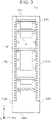
- the plate-shaped member 115 may have a plurality of holes 1151 arranged at different heights.
- the transport robot 12 can measure the current height of the placing table 121 by using a sensor mounted inward of the cutouts of the placing table 121.
- the transport robot 12 can measure the height of the placing table 121 by, for example, counting the number of detected holes 1151.
- the sensor has, for example, a light emitting unit and a light receiving unit that face each other, and can detect a hole when light from the light emitting unit is not blocked by the plate-shaped member 115.
- the transport robot 12 can thus move the placing table 121 to the height at which the transport robot 12 can pick up the item 2.
- the height of the placing table 121 may be controlled by a method other than the detection of the holes 1151.
- the transport robot 12 can also check whether the placing table 121 has been engaged with the plate-shaped member 115. This reduces the possibility of falling of the transport robot 12, and the transport robot 12 can be operated more safely.
- FIG. 4 is a perspective view showing the configuration of the transport robot 12.
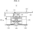
- FIG. 5 is a side view showing the configuration of the transport robot 12.
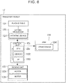
- FIG. 6 is a block diagram showing a functional configuration of the transport robot 12.
- the transport robot 12 includes the placing table 121, the moving unit 122, the lifting mechanism 123, and the arm 124.
- the transport robot 12 further includes a control unit 125 that controls the moving unit 122, the lifting mechanism 123, and the arm 124.
- the placing table 121 has a cutout as the engaging portion 1211.
- the engaging portion 1211 engages with the plate-shaped member 115 of the shelving unit 11.
- a sliding material or a roller may be provided in the engaging portion 1211 (inside the cutout). This allows the placing table 121 to slide smoothly while being engaged with the plate-shaped member 115.
- the engaging portion 1211 that is a cutout may be provided with a sensor for detecting the holes in the plate-shaped member 115. Since the engaging portion 1211 need only be a mechanism that engages with the shelving unit 11, the engaging portion 1211 is not limited to the cutout. Examples in which the engaging portion 1211 is other than the cutout (recess) will be described at the end of the description of the embodiment.
- the moving unit 122 includes: a moving unit body 1221; a pair of right and left drive wheels 1222 and a pair of front and rear driven wheels 1223 that are rotatably mounted on the moving unit body 1221; and a pair of motors 1224 that drives and rotates the drive wheels 1222.
- Each motor 1224 rotates a corresponding one of the drive wheels 1222 via a speed reducer etc.
- the motors 1224 can move the moving unit body 1221 to a desired position by rotating the drive wheels 1222 in response to a control signal from the control unit 125.
- the configuration of the moving unit 122 is by way of example only, and the moving unit 122 is not limited to this configuration.
- the moving unit 122 may have any number of drive wheels 1222 and any number of driven wheels 1223, and a known configuration can be applied as long as the moving unit body 1221 can be moved to a desired position.
- the lifting mechanism 123 lifts and lowers the placing table 121 in the vertical direction.
- the lifting mechanism 123 may be configured as a telescopic extendable mechanism that extends and contracts in the vertical direction.
- the arm 124 is attached to the placing table 121.
- a drive device 1241 is also attached to the arm 124. Specifically, the drive device 1241 is attached to a guide rail mechanism, not shown, inside the placing table 121, and an arm body can be moved in the horizontal direction.
- the drive device 1241 may further have a mechanism that rotates the arm body about the axis of the arm body.
- the transport robot 12 need not necessarily have means for storing an item into the shelving unit 11.
- the means for storing an item into the shelving unit 11 is not limited to the arm 124.
- control unit 125 controls the moving unit 122, the lifting mechanism 123, and the arm 124.
- the control unit 125 can control rotation of each drive wheel 1222 and move the moving unit body 1221 to a desired position by sending a control signal to each motor 1224 of the moving unit 122.
- the control unit 125 can control the height position of the placing table 121 by sending a control signal to a rotating device 1231 of the lifting mechanism 123.
- the control unit 125 can control the horizontal position of the arm body by sending a control signal to the drive device 1241 for the arm 124.
- the control unit 125 may control movement of the moving unit body 1221 by performing well-known control such as feedback control or robust control based on rotation information of the drive wheels 1222 detected by rotation sensors provided for the drive wheels 1222.
- the control unit 125 may control the moving unit 122, the lifting mechanism 123, and the arm 124 based on information such as distance information detected by a distance sensor such as camera or ultrasonic sensor mounted on the moving unit body 1221 and map information of a moving environment.
- the hardware for the control unit 125 is mainly configured by a microcomputer composed of: for example, a central processing unit (CPU) that performs control processing, arithmetic processing, etc.; a memory composed of a read-only memory (ROM) storing a control program, an arithmetic program, etc. that are executed by the CPU; and an interface unit (I/F) that receives and outputs signals from and to the outside.
- the CPU, the memory, and the interface unit are connected to each other via a data bus etc.
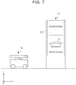
- FIG. 7 shows the state before the transport robot 12 picks up an item 2 from the shelving unit 11.
- the shelving unit 11 stores the item 2.
- the transport robot 12 advances toward the shelving unit 11.
- FIG. 7 shows an example in which the shelving unit 11 has the plate-shaped members 115 on its both front and back sides, the shelving unit 11 may have the plate-shaped member 115 only on its front side.
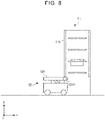
- the transport robot 12 then moves in the x direction. After the movement of the transport robot 12, the position in the x direction of the engaging portion 1211 substantially matches the position in the x direction of the plate-shaped member 115 as shown in FIG. 8 . That is, the transport robot 12 is able to engage with the plate-shaped member 115 by lifting the placing table 121.
- the transport robot 12 lifts the placing table 121.
- the engaging portion 1211 starts engaging with the plate-shaped member 115.
- a sliding material or a roller may be provided in the engaging portion 1211.
- the sliding material and the roller may be provided at the bottom of the cutout (the recessed part of the placing table 121) or may be provided on the opening side of the cutout.
- the sliding member and the roller may be provided on the plate-shaped member 115.
- the transport robot 12 lifts the placing table 121 to the height at which the transport robot 12 can pick up the item 2.
- the engaging portion 1211 and the plate-shaped member 115 are in an engaged state while the transport robot 12 is lifting the placing table 121.
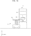
- the transport robot 12 drives the arm 124 that picks up the item 2 as shown in FIG. 10 .
- the transport robot 12 may drive an L-shaped hook in the x direction to catch and pull the item 2 by the hook.
- FIG. 11 is a plan view showing the transport robot 12 with the arm 124 being advanced.
- the arm 124 is an L-shaped hook.
- the engaging portion 1211 of the placing table 121 and the plate-shaped member 115 are in an engaged state.
- the arm 124 protrudes beyond the placing table 121.
- the transport robot 12 can catch the item 2 by the arm 124.
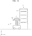
- FIG. 13 is a side view showing the item 2 placed on the placing table 121.
- FIG. 14 shows the transport robot 12 having lowered the placing table 121.
- the engaging portion 1211 of the placing table 121 and the plate-shaped member 115 of the shelving unit 11 are in a disengaged state.
- the transport robot 12 then travels with the item 2 placed on the placing table 121 and thus transports the item 2.
- the transport robot 12 can also store an item 2 into the shelving unit 11.
- the transport robot 12 engages the engaging portion 1211 with the plate-shaped member 115 of the shelving unit 11.
- the transport robot 12 then lifts the placing table 121 to the height at which the transport robot 12 can store the item 2 into the shelving unit 11.
- the transport robot 12 stores the item 2 into the shelving unit 11.
- the transport robot 12 may store the item 2 into the shelving unit 11 by catching the item 2 on the placing table 121 by the arm 124 and advancing the arm 124.
- the transport robot 12 then lowers the placing table 121, disengages the placing table 121 from the shelving unit 11, and moves from the shelving unit 11.
- the transport robot 12 may engage the placing table 121 with the surrounding environment in situations other than when picking up the item 2 from or storing the item 2 into the shelving unit 11, such as when moving between floors. In this case as well, the possibility of the transport robot 12 falling when the placing table 121 is lifted can be reduced.
- the transport robot according to the embodiment includes the placing table on which an item is placed and the plate-shaped member etc. of the shelving unit. With the placing table being engaged with the plate-shaped member etc. of the shelving unit, the transport robot places an item picked up from the shelving unit on the placing table or stores an item placed on the placing table into the shelving unit. Accordingly, the transport system according to the embodiment can reduce the possibility of the transport robot falling when picking up an item from the shelving unit or storing an item into the shelving unit.
- the transport robot according to the embodiment can reduce the possibility of the transport robot becoming unable to perform the operation of pulling an item out of the shelving unit and the operation of pushing an item into the shelving unit.
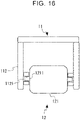
- FIG. 16 is a schematic view showing the placing table 121 of the transport robot 12 and the shelving unit 11 engaged with each other according to the first modification.
- the engaging portion 1211 is a protrusion protruding from the placing table 121.
- the side board 112 of the shelving unit 11 has a recess 1121 that engages with the engaging portion 1211 of the placing table 121.
- the transport system according to the first modification can also reduce the possibility of the transport robot falling when picking up an item from the shelving unit or storing an item into the shelving unit.
- FIG. 17 is a schematic view showing the placing table 121 of the transport robot 12 and the shelving unit 11 engaged with each other according to the second modification.
- the transport robot 12 advances a pair of arms (referred to as the second arms 126) from the placing table 121 toward the side boards 112. The tip ends of the second arms 126 thus engage with the side boards 112.
- the second arms 126 are advanced from and retracted into the placing table 121.
- the transport robot 12 may advance the second arms 126 from the placing table 121 after lifting the placing table 121 and before picking up or storing an item.
- the side board 112 of the shelving unit 11 may have the recess 1121 that engage with the second arm 126. That is, the second arm 126 may be the protrusion in the first modification and may be fitted in the recess 1121 of the shelving unit 11.
- the transport system according to the second modification can similarly reduce the possibility of the transport robot falling when picking up an item from the shelving unit or storing an item into the shelving unit.
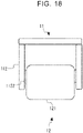
- FIG. 18 is a schematic view showing the placing table 121 and the shelving unit 11 engaged with each other according to the third modification.
- the shelving unit 11 has an engaging member 1122 formed on at least a part of the side board 112.
- the engaging member 1122 is a friction member such as high friction cushion.
- the engaging member 1122 may be rolling resistance of a roller etc.
- the side surface of the placing table 121 engages with the engaging member 1122.
- the transport robot 12 may lift the placing table 121 while rubbing the placing table 121 against the engaging member 1122.
- the transport system according to the third modification can similarly reduce the possibility of the transport robot falling when picking up an item from the shelving unit or storing an item into the shelving unit.
- FIG. 19 is a schematic view showing the placing table 121 and the shelving unit 11 engaged with each other according to the fourth modification.
- Magnets 1211a are embedded in both side surfaces of the placing table 121.
- the side boards 112 of the shelving unit 11 are made of metal.
- the placing table 121 thus magnetically engages with the shelving unit 11. Not the entire side board 112 need be made of metal, and a metal member may be disposed on a part of the side board 112.
- a magnet may be embedded in the side board 112.
- the transport robot 12 may switch the placing table 121 and the shelving unit 11 between an engaged state and a disengaged state by turning the magnetic force of the magnets 1211a on and off.
- the transport robot 12 may engage the placing table 121 with the shelving unit 11 when picking up the item 2 from or storing the item 2 into the shelving unit 11 after lifting the placing table 121.
- the transport system according to the fourth modification can also reduce the possibility of the transport robot falling when picking up an item from the shelving unit or storing an item into the shelving unit.
- FIG. 20 is a schematic view of the shelving unit 11 according to the fifth modification.
- a cover member 116 such as curtain is hung on the front side of the shelving unit 11 (side from which an item is picked up and stored).
- the side ends of the cover member 116 are engaged with the side boards of the shelving unit 11 by a zipper structure etc. There may be clearance under the cover member 116 through which the transport robot 12 can enter the shelving unit 11.
- the zipper structure is shown by dashed lines.
- the transport robot 12 engages the placing table 121 with the lower end of the cover member 116 and lifts the lower end of the cover member 116. Folds or lines that are formed when the cover member 116 is a curtain etc. are shown by long dashed short dashed lines.
- the placing table 121 has the engaging portion 1211 such as groove that engages with the cover member 116. As the lower end of the cover member 116 is moved upward, the side ends of the cover member 116 are disengaged from the side boards of the shelving unit 11 by the zipper structure accordingly.
- the mechanism of engagement between the cover member 116 and the side boards of the shelving unit 11 is not limited to the zipper structure.
- both sides of the cover member 116 may be engaged with the side boards of the shelving unit 11.
- the transport system according to the fifth modification can also reduce the possibility of the transport robot falling when picking up an item from the shelving unit or storing an item into the shelving unit.
Landscapes
- Engineering & Computer Science (AREA)
- Transportation (AREA)
- Structural Engineering (AREA)
- Mechanical Engineering (AREA)
- Civil Engineering (AREA)
- Life Sciences & Earth Sciences (AREA)
- Geology (AREA)
- Chemical & Material Sciences (AREA)
- Combustion & Propulsion (AREA)
- Warehouses Or Storage Devices (AREA)
- Manipulator (AREA)
Abstract
A transport system (1) includes a transport robot (12) configured to transport an item (2) picked up from a shelving unit (11) or to be stored into the shelving unit (11), wherein: the transport robot (12) includes a placing table (121) on which the item (2) is to be placed, and a lifting mechanism (123) configured to lift and lower the placing table (121); and the placing table (121) includes an engaging portion (1211) configured to engage with the shelving unit (11).
Description
- The present disclosure relates to a transport system, a transport method, and a non-transitory storage medium.
-
Japanese Patent No. 6413899 Japanese Patent No. 6413899 - When a transport robot picks up an item from a shelving unit or stores an item into the shelving unit, the transport robot may fall due to the moment.
- The present disclosure provides a transport system, a transport method, and a non-transitory storage medium that reduce the possibility of a transport robot falling when picking up an item from a shelving unit or storing an item into the shelving unit.
- A transport system according to a first aspect of the present disclosure includes a transport robot configured to transport an item picked up from a shelving unit or to be stored into the shelving unit. The transport robot includes a placing table on which the item is to be placed, and a lifting mechanism configured to lift and lower the placing table; and the placing table includes an engaging portion configured to engage with the shelving unit.
- A transport method according to a second aspect of the present disclosure is a method for transporting an item picked up from a shelving unit or to be stored into the shelving unit by a transport robot. The transport robot includes a placing table on which the item is to be placed, and a lifting mechanism configured to lift and lower the placing table. The transport method includes engaging the placing table with the shelving unit.
- A non-transitory storage medium according to a third aspect of the present disclosure stores instructions that are executable by a processor of a transport robot including a placing table on which an item picked up from a shelving unit or to be stored into the shelving unit is placed and configured to transport the item and that cause the processor to perform functions including causing a lifting mechanism included in the transport robot to lift and lower the placing table such that the placing table engages with the shelving unit.
- The present disclosure reduces the possibility of the transport robot falling when picking up an item from the shelving unit or storing an item into the shelving unit.
- Features, advantages, and technical and industrial significance of exemplary embodiments of the invention will be described below with reference to the accompanying drawings, in which like signs denote like elements, and wherein:
-
FIG. 1 is a schematic view showing an overview of a transport system according to an embodiment; -
FIG. 2 is a front view showing a configuration of a shelving unit according to the embodiment; -
FIG. 3 is a schematic view illustrating holes formed in the shelving unit according to the embodiment; -
FIG. 4 is a perspective view showing a configuration of a transport robot according to the embodiment; -
FIG. 5 is a side view showing the configuration of the transport robot according to the embodiment; -
FIG. 6 is a block diagram showing a functional configuration of the transport robot according to the embodiment; -
FIG. 7 is a side view showing the transport robot according to the embodiment before being coupled to the shelving unit; -
FIG. 8 is a side view showing the transport robot according to the embodiment having entered the lower part of the shelving unit; -
FIG. 9 is a side view showing the transport robot according to the embodiment having been coupled to the shelving unit; -
FIG. 10 is a side view illustrating an operation of picking up an item from the shelving unit by the transport robot according to the embodiment; -
FIG. 11 is a plan view illustrating the operation of picking up an item from the shelving unit by the transport robot according to the embodiment; -
FIG. 12 is a plan view illustrating the operation of picking up an item from the shelving unit by the transport robot according to the embodiment; -
FIG. 13 is a side view showing the transport robot according to the embodiment having picked up an item from the shelving unit; -
FIG. 14 is a side view showing the transport robot according to the embodiment having been disengaged from the shelving unit; -
FIG. 15 is a side view showing the transport robot according to the embodiment transporting an item; -
FIG. 16 is a schematic view showing the shelving unit and a placing table engaged with each other according to a first modification; -
FIG. 17 is a schematic view showing the shelving unit and the placing table engaged with each other according to a second modification; -
FIG. 18 is a schematic view showing the shelving unit and the placing table engaged with each other according to a third modification; -
FIG. 19 is a schematic view showing the shelving unit and the placing table engaged with each other according to a fourth modification; -
FIG. 20 is a schematic view of the shelving unit according to a fifth modification; and -
FIG. 21 is a schematic view showing the shelving unit and the placing table engaged with each other according to the fifth modification. - Hereinafter, the present invention will be described based on an embodiment of the invention. However, the invention according to the claims is not limited to the following embodiment. Not all of the configurations described in the embodiment are necessarily essential as means for solving the problem.
- Hereinafter, a transport system according to an embodiment will be described with reference to the drawings.
FIG. 1 is a schematic view illustrating an overview of atransport system 1 according to an embodiment. Thetransport system 1 includes ashelving unit 11 and atransport robot 12. Thetransport system 1 is a system in which thetransport robot 12 picks up an item from theshelving unit 11 to transport the item, or transports an item to theshelving unit 11 to store the item into theshelving unit 11. - The
shelving unit 11 stores items, not shown. The items may be, for example, returnable containers. Theshelving unit 11 includes atop board 111, twoside boards 112, abottom board 113, a plurality of pairs ofsupport members 114, and a plate-shaped member 115. Thetop board 111, the twoside boards 112, and thebottom board 113 form a housing of theshelving unit 11. The pairs ofsupport members 114 support the items stored in the shelving unit 11 (seeFIG. 2 ). - The plate-
shaped member 115 engages with anengaging portion 1211 of a placing table 121 that will be described later. The plate-shaped member 115 extends in the vertical direction. The plate-shaped member 115 may be provided parallel to the front side of theshelving unit 11. The plate-shaped member 115 may be provided on both right and left sides of theshelving unit 11 or may be provided on one side of theshelving unit 11. The plate-shaped member 115 protrudes inward from theside board 112. The mechanism of engagement between theshelving unit 11 and the placing table 121 is not limited to the plate-shaped member 115 and a cutout (recess). The plate-shaped member 115 is therefore not an essential constituent component in the present embodiment. For example, theside board 112 may have a recess and the placing table 121 may have a protrusion, and the recess may engage with the protrusion. Modifications will be described at the end of the description of the embodiment. - The
transport robot 12 includes the placing table 121, a movingunit 122, alifting mechanism 123, and anarm 124. The placing table 121 is a table on which an item can be placed, and is also referred to as a top board. Thetransport robot 12 moves in the horizontal direction by the movingunit 122. Thelifting mechanism 123 lifts and lowers the placing table 121. Thearm 124 picks up an item from theshelving unit 11 and places it on the placing table 121. Thearm 124 also stores an item placed on the placing table 121 into theshelving unit 11. The placement of an item may be performed by theshelving unit 11. Thearm 124 is therefore not an essential constituent component in the embodiment. Thearm 124 is also referred to as the first arm. - The placing table 121 has the engaging
portion 1211. The engagingportion 1211 is a cutout. The engagingportion 1211 engages with the plate-shapedmember 115 of theshelving unit 11. In this case, with the placing table 121 being engaged with theshelving unit 11, horizontal movement of the placing table 121 is restricted, but vertical movement of the placing table 121 is not restricted. As described above, the mechanism of engagement between the placing table 121 and theshelving unit 11 is not limited to the cutout and the plate-shapedmember 115, and modifications will be described later. - Although the
transport system 1 may include a server (not shown) that controls traveling of thetransport robot 12, thetransport robot 12 itself may generate a transport route and travel autonomously. Accordingly, a system in which processing is completed in thetransport robot 12 that does not include the server can also be included in the transport system according to the embodiment. - Next, a configuration example of the
shelving unit 11 will be described in detail with reference toFIG. 2 . Thetransport robot 12 picks up an item from, for example, a piece offurniture 3 as shown inFIG. 2 . The piece offurniture 3 has three storage spaces and can be considered to include ashelving unit 11a, ashelving unit 11b, and ashelving unit 11c. A three-dimensional Cartesian coordinate system of xyz is shown for clarity of explanation. The z direction is the vertical direction. - Since the
shelving units shelving unit 11a will be described. Theshelving unit 11a includes atop board 111a,side boards bottom board 113a, a plurality of pairs ofsupport members 114, and plate-shapedmembers transport robot 12 with the lifting mechanism in a collapsed state is shown by dashed lines. - The
top board 111a is parallel to the xy plane. Thetop board 111a may be included in a top board of the piece offurniture 3. Theside boards side board 112b is also referred to as a partition board of the piece offurniture 3. Thebottom board 113a is parallel to the xy plane. Thebottom board 113a may be included in a bottom board of the piece offurniture 3. Thetop board 111a, theside board 112a, theside board 112b, and thebottom board 113a form a housing of theshelving unit 11a. Thetop board 111a is located on the side in the positive direction of the z-axis. Thebottom board 113a is located on the side in the negative direction of the z-axis. Theside board 112a is located on the side in the negative direction of the y-axis. Theside board 112b is located on the side in the positive direction of the y-axis. Theside board 112b serves as both a side board of theshelving unit 11a on the side in the positive direction of the y-axis and a side board of theshelving unit 11b on the side in the negative direction of the y-axis. - The
bottom board 113a may be thin enough to allow thetransport robot 12 to enter theshelving unit 11a. Theshelving unit 11a need not necessarily have thebottom board 113a. - The pairs of
support members 114 extend in the depth direction (x-axis direction) and are located at regular intervals in the height direction (z-axis direction) on the inner surfaces of theside boards support members 114 stand substantially perpendicularly from the inner surfaces of theside boards item 2 has protruding portions protruding outward in the lateral direction of theitem 2. Theitem 2 can be picked up from and stored into theshelving unit 11a by sliding the protruding portions of theitem 2 on the pair ofsupport members 114 located adjacent to and facing each other. - The plate-shaped
members members members members 115 when they do not need to be identified. The plate-shapedmembers 115 may be provided on the front side of theshelving unit 11a. The plate-shapedmembers 115 may be provided on both the front and back sides of theshelving unit 11a. In this case, theitem 2 can be picked up from and stored into theshelving unit 11a from both the front and back sides of theshelving unit 11a. The plate-shapedmembers side boards member 115b of theshelving unit 11a and a plate-shapedmember 115c of theshelving unit 11b. - There is clearance between the
bottom board 113a or the ground and the lower ends of the plate-shapedmembers transport robot 12 to enter theshelving unit 11a. Thetransport robot 12 with the lifting mechanism in a collapsed state is shown by dashed lines. The width of clearance between the plate-shapedmembers 115 is greater than the width of theitem 2. The plate-shapedmembers 115 therefore will not interfere with theitem 2 when theitem 2 is picked up from and stored into theshelving unit 11a. - As shown in
FIG. 3 , the plate-shapedmember 115 may have a plurality ofholes 1151 arranged at different heights. In this case, thetransport robot 12 can measure the current height of the placing table 121 by using a sensor mounted inward of the cutouts of the placing table 121. Thetransport robot 12 can measure the height of the placing table 121 by, for example, counting the number of detectedholes 1151. The sensor has, for example, a light emitting unit and a light receiving unit that face each other, and can detect a hole when light from the light emitting unit is not blocked by the plate-shapedmember 115. Thetransport robot 12 can thus move the placing table 121 to the height at which thetransport robot 12 can pick up theitem 2. The height of the placing table 121 may be controlled by a method other than the detection of theholes 1151. - By detecting the
holes 1151 with the sensor, thetransport robot 12 can also check whether the placing table 121 has been engaged with the plate-shapedmember 115. This reduces the possibility of falling of thetransport robot 12, and thetransport robot 12 can be operated more safely. - Next, the
transport robot 12 will be described with reference toFIGS. 4 ,5 , and6 .FIG. 4 is a perspective view showing the configuration of thetransport robot 12.FIG. 5 is a side view showing the configuration of thetransport robot 12.FIG. 6 is a block diagram showing a functional configuration of thetransport robot 12. - The
transport robot 12 includes the placing table 121, the movingunit 122, thelifting mechanism 123, and thearm 124. Thetransport robot 12 further includes acontrol unit 125 that controls the movingunit 122, thelifting mechanism 123, and thearm 124. The placing table 121 has a cutout as the engagingportion 1211. The engagingportion 1211 engages with the plate-shapedmember 115 of theshelving unit 11. - A sliding material or a roller may be provided in the engaging portion 1211 (inside the cutout). This allows the placing table 121 to slide smoothly while being engaged with the plate-shaped
member 115. As described above, the engagingportion 1211 that is a cutout may be provided with a sensor for detecting the holes in the plate-shapedmember 115. Since the engagingportion 1211 need only be a mechanism that engages with theshelving unit 11, the engagingportion 1211 is not limited to the cutout. Examples in which the engagingportion 1211 is other than the cutout (recess) will be described at the end of the description of the embodiment. - The moving
unit 122 includes: a movingunit body 1221; a pair of right and leftdrive wheels 1222 and a pair of front and rear drivenwheels 1223 that are rotatably mounted on the movingunit body 1221; and a pair ofmotors 1224 that drives and rotates thedrive wheels 1222. Eachmotor 1224 rotates a corresponding one of thedrive wheels 1222 via a speed reducer etc. Themotors 1224 can move the movingunit body 1221 to a desired position by rotating thedrive wheels 1222 in response to a control signal from thecontrol unit 125. The configuration of the movingunit 122 is by way of example only, and the movingunit 122 is not limited to this configuration. For example, the movingunit 122 may have any number ofdrive wheels 1222 and any number of drivenwheels 1223, and a known configuration can be applied as long as the movingunit body 1221 can be moved to a desired position. - The
lifting mechanism 123 lifts and lowers the placing table 121 in the vertical direction. Thelifting mechanism 123 may be configured as a telescopic extendable mechanism that extends and contracts in the vertical direction. Thearm 124 is attached to the placing table 121. Adrive device 1241 is also attached to thearm 124. Specifically, thedrive device 1241 is attached to a guide rail mechanism, not shown, inside the placing table 121, and an arm body can be moved in the horizontal direction. Thedrive device 1241 may further have a mechanism that rotates the arm body about the axis of the arm body. As described above, thetransport robot 12 need not necessarily have means for storing an item into theshelving unit 11. The means for storing an item into theshelving unit 11 is not limited to thearm 124. - As described above, the
control unit 125 controls the movingunit 122, thelifting mechanism 123, and thearm 124. Thecontrol unit 125 can control rotation of eachdrive wheel 1222 and move the movingunit body 1221 to a desired position by sending a control signal to eachmotor 1224 of the movingunit 122. Thecontrol unit 125 can control the height position of the placing table 121 by sending a control signal to arotating device 1231 of thelifting mechanism 123. Thecontrol unit 125 can control the horizontal position of the arm body by sending a control signal to thedrive device 1241 for thearm 124. - The
control unit 125 may control movement of the movingunit body 1221 by performing well-known control such as feedback control or robust control based on rotation information of thedrive wheels 1222 detected by rotation sensors provided for thedrive wheels 1222. Thecontrol unit 125 may control the movingunit 122, thelifting mechanism 123, and thearm 124 based on information such as distance information detected by a distance sensor such as camera or ultrasonic sensor mounted on the movingunit body 1221 and map information of a moving environment. - The hardware for the
control unit 125 is mainly configured by a microcomputer composed of: for example, a central processing unit (CPU) that performs control processing, arithmetic processing, etc.; a memory composed of a read-only memory (ROM) storing a control program, an arithmetic program, etc. that are executed by the CPU; and an interface unit (I/F) that receives and outputs signals from and to the outside. The CPU, the memory, and the interface unit are connected to each other via a data bus etc. - Next, how the
transport robot 12 picks up anitem 2 from and stores anitem 2 into theshelving unit 11 will be described with reference toFIGS. 7 to 15 .FIG. 7 shows the state before thetransport robot 12 picks up anitem 2 from theshelving unit 11. Theshelving unit 11 stores theitem 2. Thetransport robot 12 advances toward theshelving unit 11. AlthoughFIG. 7 shows an example in which theshelving unit 11 has the plate-shapedmembers 115 on its both front and back sides, theshelving unit 11 may have the plate-shapedmember 115 only on its front side. - The
transport robot 12 then moves in the x direction. After the movement of thetransport robot 12, the position in the x direction of the engagingportion 1211 substantially matches the position in the x direction of the plate-shapedmember 115 as shown inFIG. 8 . That is, thetransport robot 12 is able to engage with the plate-shapedmember 115 by lifting the placing table 121. - Thereafter, the
transport robot 12 lifts the placing table 121. When the height of the placing table 121 reaches the lower end of the plate-shapedmember 115, the engagingportion 1211 starts engaging with the plate-shapedmember 115. As described above, a sliding material or a roller may be provided in the engagingportion 1211. The sliding material and the roller may be provided at the bottom of the cutout (the recessed part of the placing table 121) or may be provided on the opening side of the cutout. Alternatively, the sliding member and the roller may be provided on the plate-shapedmember 115. As shown inFIG. 9 , thetransport robot 12 lifts the placing table 121 to the height at which thetransport robot 12 can pick up theitem 2. The engagingportion 1211 and the plate-shapedmember 115 are in an engaged state while thetransport robot 12 is lifting the placing table 121. - Subsequently, the
transport robot 12 drives thearm 124 that picks up theitem 2 as shown inFIG. 10 . For example, thetransport robot 12 may drive an L-shaped hook in the x direction to catch and pull theitem 2 by the hook. -
FIG. 11 is a plan view showing thetransport robot 12 with thearm 124 being advanced. Thearm 124 is an L-shaped hook. At this time, the engagingportion 1211 of the placing table 121 and the plate-shapedmember 115 are in an engaged state. Thearm 124 protrudes beyond the placing table 121. By rotating thearm 124 around its axis, thetransport robot 12 can catch theitem 2 by thearm 124. - With the
item 2 caught by thearm 124, thetransport robot 12 retracts thearm 124 to place theitem 2 on the placing table 121 as shown inFIG. 12 . At this time, thearm 124 is housed in the placing table 121. As described above, since the width L1 of the clearance between the plate-shapedmembers 115 is greater than the width L2 of theitem 2, theitem 2 can be picked up using thearm 124.FIG. 13 is a side view showing theitem 2 placed on the placing table 121. - Thereafter, the
transport robot 12 lowers the placing table 121.FIG. 14 shows thetransport robot 12 having lowered the placing table 121. At this time, the engagingportion 1211 of the placing table 121 and the plate-shapedmember 115 of theshelving unit 11 are in a disengaged state. As shown inFIG. 15 , thetransport robot 12 then travels with theitem 2 placed on the placing table 121 and thus transports theitem 2. - Similarly, the
transport robot 12 can also store anitem 2 into theshelving unit 11. In this case, with theitem 2 placed on the placing table 121, thetransport robot 12 engages the engagingportion 1211 with the plate-shapedmember 115 of theshelving unit 11. Thetransport robot 12 then lifts the placing table 121 to the height at which thetransport robot 12 can store theitem 2 into theshelving unit 11. Thereafter, thetransport robot 12 stores theitem 2 into theshelving unit 11. For example, thetransport robot 12 may store theitem 2 into theshelving unit 11 by catching theitem 2 on the placing table 121 by thearm 124 and advancing thearm 124. Thetransport robot 12 then lowers the placing table 121, disengages the placing table 121 from theshelving unit 11, and moves from theshelving unit 11. Thetransport robot 12 may engage the placing table 121 with the surrounding environment in situations other than when picking up theitem 2 from or storing theitem 2 into theshelving unit 11, such as when moving between floors. In this case as well, the possibility of thetransport robot 12 falling when the placing table 121 is lifted can be reduced. - The transport robot according to the embodiment includes the placing table on which an item is placed and the plate-shaped member etc. of the shelving unit. With the placing table being engaged with the plate-shaped member etc. of the shelving unit, the transport robot places an item picked up from the shelving unit on the placing table or stores an item placed on the placing table into the shelving unit. Accordingly, the transport system according to the embodiment can reduce the possibility of the transport robot falling when picking up an item from the shelving unit or storing an item into the shelving unit.
- If the lifting mechanism is bent by the reaction force when the transport robot pulls an item out of the shelving unit or pushing an item into the shelving unit, the distance between the shelving unit and the placing table may increase. The transport robot according to the embodiment can reduce the possibility of the transport robot becoming unable to perform the operation of pulling an item out of the shelving unit and the operation of pushing an item into the shelving unit.
- In a transport system according to a first modification, the engaging portion of the placing table 121 is not a cutout but a protrusion.
FIG. 16 is a schematic view showing the placing table 121 of thetransport robot 12 and theshelving unit 11 engaged with each other according to the first modification. The engagingportion 1211 is a protrusion protruding from the placing table 121. Theside board 112 of theshelving unit 11 has arecess 1121 that engages with the engagingportion 1211 of the placing table 121. The transport system according to the first modification can also reduce the possibility of the transport robot falling when picking up an item from the shelving unit or storing an item into the shelving unit. - In a transport system according to a second modification, the transport robot engages the placing table with the shelving unit by advancing the arm from the placing table to the side boards.
FIG. 17 is a schematic view showing the placing table 121 of thetransport robot 12 and theshelving unit 11 engaged with each other according to the second modification. Thetransport robot 12 advances a pair of arms (referred to as the second arms 126) from the placing table 121 toward theside boards 112. The tip ends of thesecond arms 126 thus engage with theside boards 112. Thesecond arms 126 are advanced from and retracted into the placing table 121. In this case, thetransport robot 12 may advance thesecond arms 126 from the placing table 121 after lifting the placing table 121 and before picking up or storing an item. As in the first modification, theside board 112 of theshelving unit 11 may have therecess 1121 that engage with thesecond arm 126. That is, thesecond arm 126 may be the protrusion in the first modification and may be fitted in therecess 1121 of theshelving unit 11. The transport system according to the second modification can similarly reduce the possibility of the transport robot falling when picking up an item from the shelving unit or storing an item into the shelving unit. - In a transport system according to a third modification, the side surfaces of the placing table 121 engage with the
shelving unit 11 by an engaging member.FIG. 18 is a schematic view showing the placing table 121 and theshelving unit 11 engaged with each other according to the third modification. Theshelving unit 11 has an engagingmember 1122 formed on at least a part of theside board 112. For example, the engagingmember 1122 is a friction member such as high friction cushion. The engagingmember 1122 may be rolling resistance of a roller etc. The side surface of the placing table 121 engages with the engagingmember 1122. In this case, thetransport robot 12 may lift the placing table 121 while rubbing the placing table 121 against the engagingmember 1122. The transport system according to the third modification can similarly reduce the possibility of the transport robot falling when picking up an item from the shelving unit or storing an item into the shelving unit. - In a transport system according to a fourth modification, the side surfaces of the placing table magnetically engage with the
shelving unit 11.FIG. 19 is a schematic view showing the placing table 121 and theshelving unit 11 engaged with each other according to the fourth modification.Magnets 1211a are embedded in both side surfaces of the placing table 121. Theside boards 112 of theshelving unit 11 are made of metal. The placing table 121 thus magnetically engages with theshelving unit 11. Not theentire side board 112 need be made of metal, and a metal member may be disposed on a part of theside board 112. A magnet may be embedded in theside board 112. Thetransport robot 12 may switch the placing table 121 and theshelving unit 11 between an engaged state and a disengaged state by turning the magnetic force of themagnets 1211a on and off. In this case as well, thetransport robot 12 may engage the placing table 121 with theshelving unit 11 when picking up theitem 2 from or storing theitem 2 into theshelving unit 11 after lifting the placing table 121. The transport system according to the fourth modification can also reduce the possibility of the transport robot falling when picking up an item from the shelving unit or storing an item into the shelving unit. - In a transport system according to a fifth modification, a cover member such as curtain provided on the shelving unit engages with the upper surface of the placing table, and the placing table and the shelving unit thus engage with each other. The cover member may be a shutter.
FIG. 20 is a schematic view of theshelving unit 11 according to the fifth modification. Acover member 116 such as curtain is hung on the front side of the shelving unit 11 (side from which an item is picked up and stored). The side ends of thecover member 116 are engaged with the side boards of theshelving unit 11 by a zipper structure etc. There may be clearance under thecover member 116 through which thetransport robot 12 can enter theshelving unit 11. InFIG. 20 , the zipper structure is shown by dashed lines. - As shown in
FIG. 21 , thetransport robot 12 engages the placing table 121 with the lower end of thecover member 116 and lifts the lower end of thecover member 116. Folds or lines that are formed when thecover member 116 is a curtain etc. are shown by long dashed short dashed lines. The placing table 121 has the engagingportion 1211 such as groove that engages with thecover member 116. As the lower end of thecover member 116 is moved upward, the side ends of thecover member 116 are disengaged from the side boards of theshelving unit 11 by the zipper structure accordingly. - In this case, as shown in
FIG. 21 , horizontal movement of the placing table 121 is restricted due to the zipper structure. The mechanism of engagement between thecover member 116 and the side boards of theshelving unit 11 is not limited to the zipper structure. For example, like a sunshade shutter, both sides of thecover member 116 may be engaged with the side boards of theshelving unit 11. The transport system according to the fifth modification can also reduce the possibility of the transport robot falling when picking up an item from the shelving unit or storing an item into the shelving unit. - The present invention is not limited to the above embodiment and can be modified as appropriate without departing from the spirit and scope of the invention.
Claims (13)
- A transport system (1) comprising a transport robot (12) configured to transport an item (2) picked up from a shelving unit (11) or to be stored into the shelving unit (11), wherein:the transport robot (12) includesa placing table (121) on which the item (2) is to be placed, anda lifting mechanism (123) configured to lift and lower the placing table (121); andthe placing table (121) includes an engaging portion (1211) configured to engage with the shelving unit (11).
- The transport system (1) according to claim 1, wherein the engaging portion (1211) is configured to restrict horizontal movement of the placing table (121).
- The transport system (1) according to claim 1 or 2, wherein the transport robot (12) is further configured topick up the item (2) from the shelving unit (11) and place the item (2) on the placing table (121), andstore the item (2) placed on the placing table (121) into the shelving unit (11).
- The transport system (1) according to any one of claims 1 to 3, wherein:the shelving unit (11) includesa first protrusion protruding inward from a side board of the shelving unit (11), ora first recess formed in the side board of the shelving unit (11); andthe placing table (121) includesa second recess that engages with the first protrusion protruding inward from the side board of the shelving unit (11), ora second protrusion that engages with the first recess formed in the side board of the shelving unit (11).
- The transport system (1) according to claim 4, wherein:the shelving unit (11) includes a plate-shaped member extending in a vertical direction, the plate-shaped member being the first protrusion; andthe placing table (121) includes a cutout that engages with the plate-shaped member, the cutout being the second recess.
- The transport system (1) according to claim 5, wherein:a sliding material or a roller is provided in the cutout of the placing table (121); andthe placing table (121) is configured to slide while being engaged with the plate-shaped member.
- The transport system (1) according to claim 5 or 6, wherein:the plate-shaped member has a plurality of holes arranged at different heights; anda sensor configured to detect each of the holes in the plate-shaped member is located inward of the cutout.
- The transport system (1) according to any one of claims 1 to 3, wherein:the placing table (121) is provided with a second arm configured to be horizontally advanced from and retracted into the placing table (121); andthe second arm is configured in such a manner that a tip end of the second arm engages with a side board of the shelving unit (11).
- The transport system (1) according to any one of claims 1 to 3, wherein:an engaging member (1122) is located on at least a part of a side board of the shelving unit (11); anda side surface of the placing table (121) is configured to engage with the engaging member (1122).
- The transport system (1) according to any one of claims 1 to 3, wherein a side board of the shelving unit (11) and the placing table (121) are configured to engage with each other magnetically.
- The transport system (1) according to any one of claims 1 to 3, wherein:the shelving unit (11) includes a cover member (116) including a lower end configured to be moved upward, the cover member (116) being located on a front side of the shelving unit (11);a side end of the cover member (116) is configured to engage with a side board of the shelving unit (11); anda placing surface of the placing table (121) is configured to engage with the lower end of the cover member (116).
- A transport method for transporting an item (2) picked up from a shelving unit (11) or to be stored into the shelving unit (11) by a transport robot (12), the transport robot (12) including a placing table (121) on which the item (2) is to be placed, and a lifting mechanism (123) configured to lift and lower the placing table (121), the transport method comprising engaging the placing table (121) with the shelving unit (11).
- A non-transitory storage medium storing instructions that are executable by a processor of a transport robot (12) including a placing table on which an item (2) picked up from a shelving unit (11) or to be stored into the shelving unit (11) is placed and configured to transport the item (2) and that cause the processor to perform functions comprising causing a lifting mechanism (123) included in the transport robot (12) to lift and lower the placing table (121) such that the placing table (121) engages with the shelving unit (11).
Applications Claiming Priority (1)
| Application Number | Priority Date | Filing Date | Title |
|---|---|---|---|
| JP2021026115A JP7459819B2 (en) | 2021-02-22 | 2021-02-22 | Conveyance system and method |
Publications (1)
| Publication Number | Publication Date |
|---|---|
| EP4046943A1 true EP4046943A1 (en) | 2022-08-24 |
Family
ID=80121868
Family Applications (1)
| Application Number | Title | Priority Date | Filing Date |
|---|---|---|---|
| EP22153688.1A Withdrawn EP4046943A1 (en) | 2021-02-22 | 2022-01-27 | Transport system, transport method, and non-transitory storage medium |
Country Status (4)
| Country | Link |
|---|---|
| US (1) | US12264010B2 (en) |
| EP (1) | EP4046943A1 (en) |
| JP (1) | JP7459819B2 (en) |
| CN (1) | CN114955933B (en) |
Families Citing this family (12)
| Publication number | Priority date | Publication date | Assignee | Title |
|---|---|---|---|---|
| JP7444014B2 (en) | 2020-10-02 | 2024-03-06 | トヨタ自動車株式会社 | Transportation system and transportation method |
| JP7563219B2 (en) * | 2021-02-15 | 2024-10-08 | トヨタ自動車株式会社 | Conveying System |
| JP7571597B2 (en) | 2021-02-15 | 2024-10-23 | トヨタ自動車株式会社 | Conveying System |
| JP7502222B2 (en) * | 2021-03-16 | 2024-06-18 | トヨタホーム株式会社 | building |
| US12151922B2 (en) * | 2021-06-22 | 2024-11-26 | Symbotic Llc | Autonomous transport vehicle with synergistic vehicle dynamic response |
| US20230406639A1 (en) * | 2022-04-29 | 2023-12-21 | Kenton Brett | System and method for local tube transport |
| JP7609151B2 (en) * | 2022-10-17 | 2025-01-07 | トヨタ自動車株式会社 | TRANSPORTATION SYSTEM, TRANSPORTATION METHOD, AND PROGRAM |
| JP7643430B2 (en) * | 2022-10-18 | 2025-03-11 | トヨタ自動車株式会社 | Transport System |
| JP7800413B2 (en) * | 2022-12-22 | 2026-01-16 | トヨタ自動車株式会社 | Delivery mechanism |
| JP7754127B2 (en) * | 2023-04-18 | 2025-10-15 | トヨタ自動車株式会社 | Transport System |
| JP7750261B2 (en) * | 2023-04-18 | 2025-10-07 | トヨタ自動車株式会社 | Transport System |
| JP7816290B2 (en) * | 2023-05-31 | 2026-02-18 | トヨタ自動車株式会社 | Transport System |
Citations (4)
| Publication number | Priority date | Publication date | Assignee | Title |
|---|---|---|---|---|
| US3887097A (en) * | 1973-04-02 | 1975-06-03 | Inventio Ag | Apparatus for automatic loading and unloading of an elevator cabin |
| JPS5280978U (en) * | 1975-12-15 | 1977-06-16 | ||
| JPH0113899B2 (en) | 1978-11-28 | 1989-03-08 | Koei Chemical Co | |
| DE102015101948A1 (en) * | 2015-02-11 | 2016-08-11 | SSI Schäfer PEEM GmbH | System consisting of racking device and corresponding telescopic load handling device without width adjustment |
Family Cites Families (13)
| Publication number | Priority date | Publication date | Assignee | Title |
|---|---|---|---|---|
| JPH0885603A (en) * | 1994-09-16 | 1996-04-02 | Daifuku Co Ltd | Storage device |
| JP2925520B2 (en) * | 1997-08-12 | 1999-07-28 | 株式会社タイガーマシン製作所 | Dolly storage processing device in multi-stage storage |
| US7467024B2 (en) * | 2005-08-26 | 2008-12-16 | Flitsch Frederick A | Method and apparatus for an elevator system for a multilevel cleanspace fabricator |
| JP6137005B2 (en) * | 2014-03-19 | 2017-05-31 | トヨタ自動車株式会社 | Transfer robot and transfer method |
| JP6413899B2 (en) | 2015-04-02 | 2018-10-31 | トヨタ自動車株式会社 | Goods transfer robot |
| CN107915019A (en) * | 2016-10-09 | 2018-04-17 | 浙江国自机器人技术有限公司 | A kind of method of stock article management system, transfer robot and its Transport cargo rack |
| DE102016124876B4 (en) * | 2016-12-19 | 2025-10-16 | Concept Laser Gmbh | System for additive manufacturing of three-dimensional objects |
| JP2018126273A (en) * | 2017-02-07 | 2018-08-16 | ライフロボティクス株式会社 | Storage rack for robot picking and robot system using the same |
| DE102017112658A1 (en) * | 2017-06-08 | 2018-12-13 | Claus Henkel | logistics vehicle |
| CN209064819U (en) * | 2018-11-02 | 2019-07-05 | 杭州海康机器人技术有限公司 | Shelf and AGV vehicle |
| CN111137808B (en) * | 2018-11-02 | 2024-07-26 | 杭州海康机器人股份有限公司 | Carrier trolley |
| CN209905642U (en) * | 2019-05-15 | 2020-01-07 | 云南卓沛科技有限公司 | AGV trolley and storage system |
| CN111056205B (en) * | 2020-01-07 | 2024-11-22 | 衢州学院 | A storage transfer platform |
-
2021
- 2021-02-22 JP JP2021026115A patent/JP7459819B2/en active Active
-
2022
- 2022-01-18 CN CN202210053601.3A patent/CN114955933B/en active Active
- 2022-01-27 EP EP22153688.1A patent/EP4046943A1/en not_active Withdrawn
- 2022-02-03 US US17/591,901 patent/US12264010B2/en active Active
Patent Citations (4)
| Publication number | Priority date | Publication date | Assignee | Title |
|---|---|---|---|---|
| US3887097A (en) * | 1973-04-02 | 1975-06-03 | Inventio Ag | Apparatus for automatic loading and unloading of an elevator cabin |
| JPS5280978U (en) * | 1975-12-15 | 1977-06-16 | ||
| JPH0113899B2 (en) | 1978-11-28 | 1989-03-08 | Koei Chemical Co | |
| DE102015101948A1 (en) * | 2015-02-11 | 2016-08-11 | SSI Schäfer PEEM GmbH | System consisting of racking device and corresponding telescopic load handling device without width adjustment |
Also Published As
| Publication number | Publication date |
|---|---|
| US12264010B2 (en) | 2025-04-01 |
| US20220267091A1 (en) | 2022-08-25 |
| JP2022127887A (en) | 2022-09-01 |
| CN114955933A (en) | 2022-08-30 |
| JP7459819B2 (en) | 2024-04-02 |
| CN114955933B (en) | 2024-07-23 |
Similar Documents
| Publication | Publication Date | Title |
|---|---|---|
| EP4046943A1 (en) | Transport system, transport method, and non-transitory storage medium | |
| AU2024202265B2 (en) | Materials handling vehicle and goods storage and retrieval system comprising mobile storage carts, transporters, and materials handling vehicles | |
| CN111433139A (en) | Automatic guiding vehicle for warehouse | |
| US20180111757A1 (en) | Article Transport Facility | |
| JP2018090084A (en) | Connecting device, connected traveling device and autonomous traveling device | |
| KR20220143129A (en) | A system comprising a multi-level warehouse rack system comprising a tote delivery area, a material handling vehicle, a transporter, and methods of using the same | |
| JP5928709B2 (en) | Safe deposit system | |
| JP7524668B2 (en) | Automated Warehouse System | |
| JP7004248B2 (en) | Coupling device, connecting mobile device and autonomous mobile device | |
| WO2022161407A1 (en) | Container carrying system, robot, and container carrying method | |
| JP2020508224A (en) | Article transfer robot and control method thereof | |
| JP7609151B2 (en) | TRANSPORTATION SYSTEM, TRANSPORTATION METHOD, AND PROGRAM | |
| KR20250096838A (en) | Control method for pulling cargo from cargo shelf by cargo loading and unloading device | |
| CN220843994U (en) | Transfer robot | |
| JP6298315B2 (en) | Transport cart | |
| JP5190694B2 (en) | Learning device in article storage facility | |
| CN113734681B (en) | A positioning device, shelf and storage logistics system | |
| JP2015214381A (en) | Carriage | |
| CN222906545U (en) | Hook mechanism, pick-and-place device, robot and storage system | |
| JP6849767B1 (en) | Cargo handling system and control method | |
| JP2020040459A (en) | Coupling device, coupled travel device and autonomous travel device | |
| US20250033893A1 (en) | Article Transferrer | |
| KR102745317B1 (en) | The Method And System Of 2-Axis Automatic Loading And Unloading Using AMR, Including Transfer Robot And Control Server | |
| CN223878742U (en) | A warehousing system | |
| CN221252594U (en) | Pick-and-place device and transfer robot |
Legal Events
| Date | Code | Title | Description |
|---|---|---|---|
| PUAI | Public reference made under article 153(3) epc to a published international application that has entered the european phase |
Free format text: ORIGINAL CODE: 0009012 |
|
| STAA | Information on the status of an ep patent application or granted ep patent |
Free format text: STATUS: REQUEST FOR EXAMINATION WAS MADE |
|
| 17P | Request for examination filed |
Effective date: 20220213 |
|
| AK | Designated contracting states |
Kind code of ref document: A1 Designated state(s): AL AT BE BG CH CY CZ DE DK EE ES FI FR GB GR HR HU IE IS IT LI LT LU LV MC MK MT NL NO PL PT RO RS SE SI SK SM TR |
|
| STAA | Information on the status of an ep patent application or granted ep patent |
Free format text: STATUS: THE APPLICATION HAS BEEN WITHDRAWN |
|
| 18W | Application withdrawn |
Effective date: 20230714 |