EP4046844A2 - Réservoirs de carburant et véhicules de lancement réutilisables comportant ces réservoirs de carburant - Google Patents
Réservoirs de carburant et véhicules de lancement réutilisables comportant ces réservoirs de carburant Download PDFInfo
- Publication number
- EP4046844A2 EP4046844A2 EP22156645.8A EP22156645A EP4046844A2 EP 4046844 A2 EP4046844 A2 EP 4046844A2 EP 22156645 A EP22156645 A EP 22156645A EP 4046844 A2 EP4046844 A2 EP 4046844A2
- Authority
- EP
- European Patent Office
- Prior art keywords
- petal
- length
- containment
- partial
- full
- Prior art date
- Legal status (The legal status is an assumption and is not a legal conclusion. Google has not performed a legal analysis and makes no representation as to the accuracy of the status listed.)
- Granted
Links
Images

Classifications
-
- B—PERFORMING OPERATIONS; TRANSPORTING
- B60—VEHICLES IN GENERAL
- B60K—ARRANGEMENT OR MOUNTING OF PROPULSION UNITS OR OF TRANSMISSIONS IN VEHICLES; ARRANGEMENT OR MOUNTING OF PLURAL DIVERSE PRIME-MOVERS IN VEHICLES; AUXILIARY DRIVES FOR VEHICLES; INSTRUMENTATION OR DASHBOARDS FOR VEHICLES; ARRANGEMENTS IN CONNECTION WITH COOLING, AIR INTAKE, GAS EXHAUST OR FUEL SUPPLY OF PROPULSION UNITS IN VEHICLES
- B60K15/00—Arrangement in connection with fuel supply of combustion engines or other fuel consuming energy converters, e.g. fuel cells; Mounting or construction of fuel tanks
- B60K15/03—Fuel tanks
-
- B—PERFORMING OPERATIONS; TRANSPORTING
- B64—AIRCRAFT; AVIATION; COSMONAUTICS
- B64G—COSMONAUTICS; VEHICLES OR EQUIPMENT THEREFOR
- B64G1/00—Cosmonautic vehicles
- B64G1/22—Parts of, or equipment specially adapted for fitting in or to, cosmonautic vehicles
- B64G1/40—Arrangements or adaptations of propulsion systems
- B64G1/402—Propellant tanks; Feeding propellants
- B64G1/4021—Tank construction; Details thereof
-
- B—PERFORMING OPERATIONS; TRANSPORTING
- B64—AIRCRAFT; AVIATION; COSMONAUTICS
- B64D—EQUIPMENT FOR FITTING IN OR TO AIRCRAFT; FLIGHT SUITS; PARACHUTES; ARRANGEMENT OR MOUNTING OF POWER PLANTS OR PROPULSION TRANSMISSIONS IN AIRCRAFT
- B64D37/00—Arrangements in connection with fuel supply for power plant
- B64D37/02—Tanks
- B64D37/06—Constructional adaptations thereof
- B64D37/08—Internal partitioning
-
- B—PERFORMING OPERATIONS; TRANSPORTING
- B64—AIRCRAFT; AVIATION; COSMONAUTICS
- B64D—EQUIPMENT FOR FITTING IN OR TO AIRCRAFT; FLIGHT SUITS; PARACHUTES; ARRANGEMENT OR MOUNTING OF POWER PLANTS OR PROPULSION TRANSMISSIONS IN AIRCRAFT
- B64D37/00—Arrangements in connection with fuel supply for power plant
- B64D37/02—Tanks
- B64D37/14—Filling or emptying
- B64D37/20—Emptying systems
- B64D37/26—Jettisoning of fuel
-
- B—PERFORMING OPERATIONS; TRANSPORTING
- B64—AIRCRAFT; AVIATION; COSMONAUTICS
- B64G—COSMONAUTICS; VEHICLES OR EQUIPMENT THEREFOR
- B64G1/00—Cosmonautic vehicles
- B64G1/002—Launch systems
- B64G1/006—Reusable launch rockets or boosters
-
- B—PERFORMING OPERATIONS; TRANSPORTING
- B64—AIRCRAFT; AVIATION; COSMONAUTICS
- B64G—COSMONAUTICS; VEHICLES OR EQUIPMENT THEREFOR
- B64G1/00—Cosmonautic vehicles
- B64G1/14—Space shuttles
Definitions
- Reusable launch vehicles are designed to dump residual fuel to minimize the landing weight.
- the fuel is dumped through a dump tube, positioned around a sump.
- the residual fuel is forced away from the sump and also from the dump tube. This movement of the residual fuel complicates the fuel dumping process. As such, the residual fuel should be maintained proximate to the sump, even when the reusable launch vehicle decelerates.
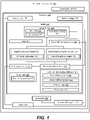
- a fuel tank comprising an interior wall, a sump, and a baffle that comprises a center fitting, a full-length containment petal, and a dump tube.
- the full-length containment petal comprises a full-length side edge, extending radially outward from the center fitting.
- the partial-length containment petal comprises a partial-length side edge, extending radially outward from the center fitting.
- the dump tube is connected to the sump.
- the full-length side edge of the full-length containment petal is longer than the partial-length side edge of the partial-length containment petal. All of the partial-length side edge of the partial-length containment petal is attached to a linear portion of the full-length side edge of the full-length containment petal.
- the baffle is used to control the fuel distribution inside the fuel tank. More specifically, the baffle is configured to enable the fuel to flow into the portion of the fuel tank between the baffle and the sump.
- the baffle comprises a partial-length containment petal, which is spaced away from the interior wall of the fuel tank, enabling the fuel to flow between the partial-length containment petal and the interior wall 105.
- the baffle prevents a rapid escape of the fuel from this portion of the fuel tank, when the fuel tank is subjected to acceleration (e.g., when the reusable launch vehicle containing this fuel tank decelerates during the landing). As such, the fuel remains in this portion of the fuel tank and can be dumped from the fuel tank through the dump tube.
- solid lines, if any, connecting various elements and/or components may represent mechanical, electrical, fluid, optical, electromagnetic and other couplings and/or combinations thereof.
- "coupled” means associated directly as well as indirectly.
- a member A may be directly associated with a member B, or may be indirectly associated therewith, e.g., via another member C. It will be understood that not all relationships among the various disclosed elements are necessarily represented. Accordingly, couplings other than those depicted in the block diagrams may also exist.
- Dashed lines, if any, connecting blocks designating the various elements and/or components represent couplings similar in function and purpose to those represented by solid lines; however, couplings represented by the dashed lines may either be selectively provided or may relate to alternative examples of the subject matter, disclosed herein.
- elements and/or components, if any, represented with dashed lines indicate alternative examples of the subject matter, disclosed herein.
- One or more elements shown in solid and/or dashed lines may be omitted from a particular example without departing from the scope of the subject matter, disclosed herein.
- Environmental elements, if any, are represented with dotted lines. Virtual (imaginary) elements may also be shown for clarity.
- FIG. 1 may be combined in various ways without the need to include other features described in FIG. 1 , other drawing figures, and/or the accompanying disclosure, even though such combination or combinations are not explicitly illustrated herein. Similarly, additional features not limited to the examples presented, may be combined with some or all of the features shown and described herein.
- the blocks may represent operations and/or portions thereof and lines connecting the various blocks do not imply any particular order or dependency of the operations or portions thereof. Blocks represented by dashed lines indicate alternative operations and/or portions thereof. Dashed lines, if any, connecting the various blocks represent alternative dependencies of the operations or portions thereof. It will be understood that not all dependencies among the various disclosed operations are necessarily represented.
- FIG. 7 and the accompanying disclosure describing the operations of the method(s) set forth herein should not be interpreted as necessarily determining a sequence in which the operations are to be performed. Rather, although one illustrative order is indicated, it is to be understood that the sequence of the operations may be modified when appropriate. Accordingly, certain operations may be performed in a different order or simultaneously. Additionally, those skilled in the art will appreciate that not all operations described need to be performed.
- first, second, etc. are used herein merely as labels and are not intended to impose ordinal, positional, or hierarchical requirements on the items to which these terms refer. Moreover, reference to, e.g., a “second” item does not require or preclude the existence of, e.g., a "first” or lower-numbered item, and/or, e.g., a "third" or higher-numbered item.
- a system, apparatus, structure, article, element, component, or hardware “configured to” perform a specified function is indeed capable of performing the specified function without any alteration, rather than merely having the potential to perform the specified function after further modification.
- the system, apparatus, structure, article, element, component, or hardware “configured to” perform a specified function is specifically selected, created, implemented, utilized, programmed, and/or designed for the purpose of performing the specified function.
- "configured to” denotes existing characteristics of a system, apparatus, structure, article, element, component, or hardware which enable the system, apparatus, structure, article, element, component, or hardware to perform the specified function without further modification.
- a system, apparatus, structure, article, element, component, or hardware described as being “configured to” perform a particular function may additionally or alternatively be described as being “adapted to” and/or as being “operative to” perform that function.
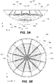
- fuel tank 100 comprises interior wall 105, sump 110, and baffle 120.
- Baffle 120 comprises center fitting 124 and full-length containment petal 132 that comprises full-length side edge 133, extending radially outward from center fitting 124.
- Baffle 120 addtionally comprises partial-length containment petal 134 that comprises partial-length side edge 135, extending radially outward from center fitting 124.
- Baffle 120 also comprises dump tube 118, connected to sump 110.
- Full-length side edge 133 of full-length containment petal 132 is longer than partial-length side edge 135 of partial-length containment petal 134. All of partial-length side edge 135 of partial-length containment petal 134 is attached to a linear portion of full-length side edge 133 of full-length containment petal 132.
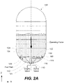
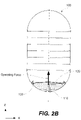
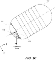
- Baffle 120 is used to control the fuel distribution inside fuel tank 100. More specifically, baffle 120 is configured to enable the fuel to flow into a portion of fuel tank 100 between baffle 120 and sump 110 as, for example, is schematically shown in FIG. 2A . Baffle 120 comprises partial-length containment petal 134, which is spaced away from interior wall 105, enabling the fuel to flow between partial-length containment petal 134 and interior wall 105. Furthermore, baffle 120 prevents a rapid escape of the fuel from this portion of fuel tank 100, e.g., when is subjected to acceleration (e.g., when the reusable launch vehicle decelerates during landing) as, for example, is schematically shown in FIG. 2B . As such, the fuel remains in this portion of fuel tank 100 and can be dumped from fuel tank 100 through dump tube 118 as, for example, is schematically shown in FIG. 2C .
- acceleration e.g., when the reusable launch vehicle decelerates during landing
- interior wall 105 of fuel tank 100 is formed from a composite material, which complicates the attachment of various components to interior wall 105.
- various conventional attachment techniques e.g., welding
- baffle 120 is supported by sump 110, instead of being supported by interior wall 105.
- Full-length containment petal 132 extends to interior wall 105 and, in some examples, forms a seal with interior wall 105.
- Full-length containment petals 132 block the fuel from passing between full-length containment petal 132 and interior wall 105.
- partial-length containment petal 134 is spaced away from interior wall 105 and enables the fuel to pass between partial-length containment petal 134 and interior wall 105.
- a larger portion of the interior cross-sectional area of fuel tank 100 is blocked by baffle 120 thereby ensuring the fuel containment in the portion of fuel tank 100 between baffle 120 and sump 110.
- This fuel containment enables dump tube 118 to remove the remaining fuel from fuel tank 100 at various operation conditions, e.g., when fuel tank 100 decelerates.
- baffle 120 Forming baffle 120 from center fitting 124 and multiple petals, such as full-length containment petal 132 and partial-length containment petal 134, enables the installation of baffle 120 through a small opening on one end of fuel tank 100. This opening is later sealed with sump 110. The opening is smaller than the inside diameter of the cylindrical portion of fuel tank 100. When installed inside fuel tank 100, baffle 120 has a larger diameter than this opening. Specifically, separate components of baffle 120, such as center fitting 124, full-length containment petal 132, and partial-length containment petal 134 are fed through the opening and then assembled inside fuel tank 100, collectively forming baffle 120. As such, interior wall 105 does not require additional joints and can be formed substantially monolithic.
- baffle 120 further comprises center-fitting support strut 141, connecting center fitting 124 to sump 110.
- Center-fitting support strut 141 attaches center fitting 124 to sump 110 and also supports center fitting 124, relative to sump 110.
- This sump-supporting feature eliminates the need for attaching baffle 120 to interior wall 105.
- baffle 120 is formed from a metal
- interior wall 105 is formed from a composite material.
- Metals and composite materials have different coefficients of thermal expansion (CTEs), which complicates the process of maintaining any direct connection over the wide temperature range.
- CTEs coefficients of thermal expansion
- many common joining techniques e.g., welding
- baffle 120 other components of baffle 120, e.g., full-length containment petal 132 and partial-length containment petal 134, are also attached to center fitting 124. As such, these other components are also indirectly supporting by center-fitting support strut 141 relative to sump 110.
- baffle 120 further comprises petal support strut 142, connecting at least one of full-length containment petal 132 or partial-length containment petal 134 to sump 110.
- Petal support strut 142 supports full-length containment petal 132 or partial-length containment petal 134 relative to sump 110.
- This sump-supporting feature eliminates the need for attaching baffle 120 to interior wall 105
- baffle 120 is formed from a metal
- interior wall 105 is formed from a composite material.
- Metals and composite materials have different coefficients of thermal expansion (CTEs), which complicates the process of maintaining any direct connection over the wide temperature range.
- CTEs coefficients of thermal expansion
- many common joining techniques e.g., welding
- full-length containment petal 132 or partial-length containment petal 134 is connected to petal support strut 142. In one or more examples, both full-length containment petal 132 and partial-length containment petal 134 are connected to petal support strut 142.
- petal support strut 142 is connected to at least one of full-length side edge 133 of full-length containment petal 132 or partial-length side edge 135 of partial-length containment petal 134.
- full-length side edge 133 of full-length containment petal 132 or partial-length side edge 135 of partial-length containment petal 134 enables supporting multiple petals with a single petal support strut.
- full-length side edge 133 of full-length containment petal 132 or partial-length side edge 135 of partial-length containment petal 134 can be also connected to the edge of an adjacent petal.
- petal support strut 142 can support two petals at the same time.
- petal support strut 142 is connected to full-length side edge 133 of full-length containment petal 132. In the same or other examples, petal support strut 142 is connected to partial-length side edge 135 of partial-length containment petal 134. For example, petal support strut 142 is connected to both full-length side edge 133 of full-length containment petal 132 and partial-length side edge 135 of partial-length containment petal 134. Alternatively, petal support strut 142 is connected to full-length side edge 133 of full-length containment petal 132 or partial-length side edge 135 of partial-length containment petal 134 but not both.
- baffle 120 further comprises petal side-edge stiffener 150, attached to at least one of full-length side edge 133 of full-length containment petal 132 or partial-length side edge 135 of partial-length containment petal 134.
- Petal support strut 142 is attached to petal side-edge stiffener 150.
- Petal side-edge stiffener 150 reinforces at least one of full-length side edge 133 of full-length containment petal 132 or partial-length side edge 135 of partial-length containment petal 134.
- full-length containment petal 132 and partial-length side edge 135 of partial-length containment petal 134 are formed as thin sheets to reduce the overall weight of fuel tank 100.
- Petal side-edge stiffener 150 extends out of the plane, providing some additional rigidity to the overall assembly formed by petal side-edge stiffener 150 and at least one of full-length containment petal 132 and partial-length containment petal 134.
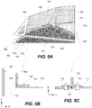
- petal side-edge stiffener 150 interconnects to two adjacent petals as, e.g., is shown in FIG. 3B .
- petal side-edge stiffener 150 interconnects full-length containment petal 132 and partial-length containment petal 134 as, e.g., is shown in FIGS. 5C .
- petal side-edge stiffener 150 interconnects two full-length containment petals.
- petal side-edge stiffener 150 interconnects two partial-length containment petals as, e.g., is shown in FIG. 5A .
- petal support strut 142 is connected to both full-length containment petal 132 and partial-length containment petal 134.
- petal support strut 142 When petal support strut 142 is connected to multiple petals, such as full-length containment petal 132 and partial-length containment petal 134, fewer petal support struts are needed in fuel tank 100. As such, fuel tank 100 has a lower overall weight, which is desirable for many applications. In some examples, petal support strut 142 is connected to two full-length containment petals. In other examples, petal support strut 142 is connected to two partial-length containment petals.
- petal support strut 142 is connected to both full-length side edge 133 of full-length containment petal 132 and partial-length side edge 135 of partial-length containment petal 134.
- edges of multiple petals such as full-length side edge 133 of full-length containment petal 132 and partial-length side edge 135 partial-length containment petal 134, enables using fewer petal support struts in fuel tank 100. As such, the overall weight of fuel tank 100 is reduced, which is desirable for many applications.
- full-length side edge 133 of full-length containment petal 132 and partial-length side edge 135 partial-length containment petal 134 are interconnected, in addition to being connected to petal support strut 142. This overall connection helps to strengthen the assembly.
- baffle 120 further comprises petal side-edge stiffener 150.
- Petal side-edge stiffener 150 attaches full-length side edge 133 of full-length containment petal 132 to partial-length side edge 135 of partial-length containment petal 134.
- Petal side-edge stiffener 150 is connected to petal support strut 142.
- Petal side-edge stiffener 150 reinforces full-length side edge 133 of full-length containment petal 132 and partial-length side edge 135 of partial-length containment petal 134. Furthermore, petal side-edge stiffener 150 reinforces full-length side edge 133 of full-length containment petal 132 and partial-length side edge 135 of partial-length containment petal 134 thereby reinforcing the overall structure of baffle 120 and the ability of baffle 120 to withstand forces from the fuel. For example, full-length containment petal 132 and partial-length side edge 135 of partial-length containment petal 134 are formed as thin sheets to reduce the overall weight of fuel tank 100.
- Petal side-edge stiffener 150 extends out of the plane, providing additional rigidity to the overall assembly of petal side-edge stiffener 150, full-length containment petal 132, and partial-length containment petal 134. Therefore, petal support strut 142 is connected to the reinforced petal edges.
- petal side-edge stiffener 150 extends along the entire length of partial-length side edge 135 of partial-length containment petal 134. In more specific examples, petal side-edge stiffener 150 extends along the entire length of full-length side edge 133 of full-length containment petal 132.
- baffle 120 further comprises petal side-edge stiffener 150, attached to center fitting 124 and to at least one of full-length side edge 133 of full-length containment petal 132 or partial-length side edge 135 of partial-length containment petal 134.
- Petal side-edge stiffener 150 reinforces at least one of full-length side edge 133 of full-length containment petal 132 or partial-length side edge 135 of partial-length containment petal 134.
- full-length containment petal 132 and partial-length side edge 135 of partial-length containment petal 134 are formed as thin sheets to reduce the overall weight of fuel tank 100.
- Petal side-edge stiffener 150 extends out of the plane, providing additional rigidity to the overall assembly of petal side-edge stiffener 150 at least one of full-length containment petal 132 and partial-length containment petal 134.
- petal side-edge stiffener 150 interconnects center fitting 124 and full-length containment petal 132 or partial-length containment petal 134 thereby ensuring the overall mechanical integrity of baffle 120. This attachment also provides support to center fitting 124.
- petal side-edge stiffener 150 interconnects to two adjacent petals as, e.g., is shown in FIG. 3B .
- petal side-edge stiffener 150 interconnects full-length containment petal 132 and partial-length containment petal 134 as, e.g., is shown in FIGS. 5C .
- petal side-edge stiffener 150 interconnects two full-length containment petals.
- petal side-edge stiffener 150 interconnects two partial-length containment petals as, e.g., is shown in FIG. 5A .
- baffle 120 further comprises petal side-edge stiffener 150, attached to center fitting 124 and to both full-length side edge 133 of full-length containment petal 132 and partial-length side edge 135 of partial-length containment petal 134.
- Petal side-edge stiffener 150 reinforces both full-length side edge 133 of full-length containment petal 132 and partial-length side edge 135 of partial-length containment petal 134.
- full-length containment petal 132 and partial-length side edge 135 of partial-length containment petal 134 are formed as thin sheets to reduce the overall weight of fuel tank 100.
- Petal side-edge stiffener 150 extends out of the plane, providing additional rigidity of the overall assembly of petal side-edge stiffener 150 at least one of full-length containment petal 132 and partial-length containment petal 134.
- petal side-edge stiffener 150 interconnects center fitting 124 and full-length containment petal 132 and partial-length containment petal 134 thereby ensuring the overall mechanical integrity of baffle 120. This attachment also provides support to center fitting 124.
- petal side-edge stiffener 150 extends along the entire length of partial-length side edge 135 of partial-length containment petal 134. In more specific examples, petal side-edge stiffener 150 extends along the entire length of full-length side edge 133 of full-length containment petal 132.
- example 11 of the subject matter, disclosed herein.
- full-length containment petal 132 is sealed against interior wall 105.
- Partial-length containment petal 134 is spaced away from interior wall 105, forming gap 129 between partial-length containment petal 134 and interior wall 105.
- full-length containment petal 132 against interior wall 105 ensures that the fuel does not flow between full-length containment petal 132 and interior wall 105 and that the fuel is contained in a portion of fuel tank 100 between baffle 120 and sump 110.
- This fuel containment ensures that the fuel can be dumped even when fuel tank 100 decelerates, e.g., as shown in FIGS. 2B and 2C .
- gap 129 enables the fuel to flow into this portion of fuel tank 100 as, e.g., is shown in FIG. 2A .
- the surface area ratio of full-length containment petal 132 and partial-length containment petal 134 define the containment properties of baffle 120.
- fuel tank 100 further comprises flexible seal 137 that seals full-length containment petal 132 against interior wall 105.
- Flexible seal 137 ensures that the fuel cannot flow between full-length containment petal 132 against interior wall 105.
- full-length containment petal 132 and interior wall 105 are formed from different materials and have different CTEs. Flexible seal 137 ensures that that the space between full-length containment petal 132 and interior wall 105 remains sealed over a wide range of temperatures.
- flexible seal 137 is formed from a flexible material, such as a polymer.
- dump tube 118 comprises dump-tube opening 119.
- Gap 129 and dump-tube opening 119 are located on opposite sides of center fitting 124.
- Dump-tube opening 119 is used to collect the fuel from fuel tank 100. The fuel collection is particularly challenging when fuel tank 100 is near empty as, e.g., is shown in FIG. 2C .
- baffle 120 contains the remaining fuel in the portion of fuel tank 100 between baffle 120 and sump 110.
- dump-tube opening 119 allows the fuel into this portion of fuel tank 100.
- fuel tank 100 is tilted such that the remaining fuel is kept away from dump-tube opening 119, such that the fuel does not escape from this portion of fuel tank 100 through dump-tube opening 119.
- dump-tube opening 119 faces interior wall 105 to ensure better fuel collection when fuel tank 100 is tilted toward this portion of interior wall 105.
- fuel tank 100 further comprises slosh baffle 180, attached to baffle 120 such that full-length containment petal 132 and partial-length containment petal 134 are located between slosh baffle 180 and sump 110.
- Slosh baffle 180 dampens the fuel movement in fuel tank 100, e.g., along interior wall 105. For example, when fuel tank 100 is partially filled, any accelerations of fuel tank 100 causes the fuel slosh. This fuel slosh, if not mitigated, can adversely affect the overall system, e.g, orientation. Furthermore, attaching slosh baffle 180 to baffle 120 eliminated the need to form connections to interior wall 105 of fuel tank 100, which can be challenging.
- slosh baffle 180 is attached to baffle 120 along the perimeter of interior wall 105. In other words, slosh baffle 180 forms a ring within fuel tank 100, proximate to interior wall 105.
- fuel tank 100 further comprises slosh-baffle support 182 that attaches slosh baffle 180 to at least one of full-length containment petal 132 or partial-length containment petal 134.
- Slosh baffle 180 dampens the fuel movement in fuel tank 100, e.g., along interior wall 105. As such, slosh baffle 180 needs to be well support within fuel tank 100. Attaching slosh baffle 180 to baffle 120 eliminated the need to form connections to interior wall 105 of fuel tank 100, which can be challenging. Baffle 120 connects slosh baffle 180 to sump 110 of fuel tank 100.
- slosh baffle 180 comprises multiple petals. Slosh-baffle support 182 is used to interconnect two adjacent petals of slosh baffle 180. Slosh-baffle support 182 can also interconnect these two adjacent petals.
- baffle 120 further comprises petal side-edge stiffener 150, attached to at least one of full-length side edge 133 of full-length containment petal 132 or partial-length side edge 135 of partial-length containment petal 134. Slosh-baffle support 182 is attached to petal side-edge stiffener 150.
- Petal side-edge stiffener 150 reinforces at least one of full-length side edge 133 of full-length containment petal 132 or partial-length side edge 135 of partial-length containment petal 134.
- full-length containment petal 132 and partial-length side edge 135 of partial-length containment petal 134 are formed as thin sheets to reduce the overall weight of fuel tank 100.
- Petal side-edge stiffener 150 extends out of the plane providing additional rigidity to the overall assembly. Slosh-baffle support 182 is connected to this reinforced assembly.
- slosh-baffle support 182 is supported by multiple components at the same time, e.g., petal side-edge stiffener 150 and at least one of full-length side edge 133 of full-length containment petal 132 or partial-length side edge 135 of partial-length containment petal 134.
- slosh-baffle support 182 and petal side-edge stiffener 150 can be riveted together. It should be noted that this attachment is performed inside fuel tank 100.
- fuel tank 100 further comprises slosh-baffle support 182 that attaches slosh baffle 180 to both full-length containment petal 132 and partial-length containment petal 134.
- slosh-baffle support 182 attaches slosh baffle 180 to both full-length containment petal 132 and partial-length containment petal 134, slosh-baffle support 182 i supported by both full-length containment petal 132 and partial-length containment petal 134.
- slosh-baffle support 182 and each of full-length containment petal 132 and partial-length containment petal 134 are contemplated.
- slosh-baffle support 182 and each full-length containment petal 132 and partial-length containment petal 134 can be riveted together. It should be noted that this attachment is performed inside fuel tank 100.
- baffle 120 further comprises petal side-edge stiffener 150, attached to both full-length side edge 133 of full-length containment petal 132 and partial-length side edge 135 of partial-length containment petal 134. Slosh-baffle support 182 is attached to petal side-edge stiffener 150.
- petal side-edge stiffener 150 reinforces both full-length side edge 133 of full-length containment petal 132 and partial-length side edge 135 of partial-length containment petal 134. Furthermore, in these examples, petal side-edge stiffener 150 interconnects full-length side edge 133 of full-length containment petal 132 and partial-length side edge 135 of partial-length containment petal 134. Therefore, attaching slosh-baffle support 182 to petal side-edge stiffener 150 effectively connects slosh-baffle support 182 to full-length containment petal 132 and partial-length containment petal 134.
- slosh-baffle support 182 and petal side-edge stiffener 150 can be riveted together. It should be noted that this attachment is performed inside fuel tank 100.
- example 19 of the subject matter, disclosed herein.
- an angle from 60° to 80° is formed between slosh baffle 180 and full-length containment petal 132.
- the angle between slosh baffle 180 and full-length containment petal 132 is selected to redirect the fuel inside fuel tank 100 and to mitigate undesirable slosh conditions. Furthermore, this angle controls the forces, applied by the fuel (e.g., during acceleration of fuel tank 100). For example, when the fuel travels along interior wall 105, slosh baffle 180 can redirect the fuel toward interior wall 105, thereby reducing the impact of the fuel on baffle 120.
- full-length containment petal 132 is controlled by the attachnment structures, such as slosh-baffle support 182. It should be noted that full-length containment petal 132 is not necessarily perpendicular to interior wall 105.
- example 20 of the subject matter, disclosed herein. According to example 20, which encompasses any one of examples 14 to 19, above an angle from 60° to 80° is formed between slosh baffle 180 and partial-length containment petal 134.
- the angle between slosh baffle 180 and partial-length containment petal 134 is selected to redirect the fuel inside fuel tank 100 and to mitigate undesirable slosh conditions. Furthermore, this angle controls the forces, applied by the fuel (e.g., during acceleration of fuel tank 100). For example, when the fuel travels along interior wall 105, slosh baffle 180 can redirect the fuel toward interior wall 105 thereby reducing the impact of the fuel on baffle 120.
- slosh baffle 180 and partial-length containment petal 134 are controlled by the attachment structures, such as slosh-baffle support 182. It should be noted that full-length containment petal 132 is not necessarily perpendicular to interior wall 105.
- center fitting 124 comprises first side 126, facing away from sump 110, and second side 127, facing toward sump 110.
- Each of full-length containment petal 132 and partial-length containment petal 134 forms an angle from 5° to 15° with first side 126 of center fitting 124.
- the angle of 5° to 15° between each of full-length containment petal 132 and partial-length containment petal 134 and first side 126 of center fitting 124 helps to manage the gas flow inside fuel tank 100. Specifically, as the fuel is being removed from fuel tank 100, an increasing volume inside fuel tank 100 is occupied by the gas (e.g., backfilled into fuel tank 100). Some gas can enter a portion of fuel tank 100 between baffle 120 and sump 110. The angle of between each of full-length containment petal 132 and partial-length containment petal 134 and first side 126 of center fitting 124 ensures that this gas stays close to center fitting 124 and, for example, away from dump tube 118 at least during certain orientations of fuel tank 100.
- the angle between first side 126 of center fitting 124 and each of full-length containment petal 132 and partial-length containment petal 134 is set by the design of center fitting 124 and each of full-length containment petal 132 and partial-length containment petal 134,
- center fitting 124 comprises a side edge, extending between first side 126 and second side 127 and to which each of full-length containment petal 132 and partial-length containment petal 134 is attached.
- center fitting 124 comprises ventilation opening 125 that extends from first side 126 to second side 127 of center fitting 124.
- Ventilation opening 125 helps to manage the gas flow inside fuel tank 100. Specifically, as the fuel is being removed from fuel tank 100, an increasing volume inside fuel tank 100 is occupied by the gas (e.g., backfilled into fuel tank 100). Some gas can enter a portion of fuel tank 100 between baffle 120 and sump 110 and stays close to center fitting 124. Ventilation opening 125 in center fitting 124 enables this gas to escape through center fitting 124.
- the size of ventilation opening 125 is selected such that the gascan to escape through center fitting 124, while the fuel is contained by center fitting 124. If any amount of the fuel passes through center fitting 124, this amount is insignificant.
- fuel tank 100 further comprises petal peripheral-edge stiffener 160, attached to partial-length containment petal 134 such that petal peripheral-edge stiffener 160 partially overlaps partial-length side edge 135 of partial-length containment petal 134 at one end of partial-length side edge 135.
- Partial-length containment petal 134 does not extend or connected to interior wall 105. Instead, a wall-facing edge of partial-length containment petal 134 is spaced apart from interior wall 105. Petal peripheral-edge stiffener 160 is attached to partial-length containment petal 134 at this wall-facing edge to provide additional rigidity to the edge. As such, when the fule passes through space between partial-length containment petal 134 is spaced apart from interior wall 105, this edge is not deformed.
- petal peripheral-edge stiffener 160 extend between two partial-length side edges of partial-length containment petal 134. In other words, petal peripheral-edge stiffener 160 spans the entire length of the wall-facing edge of partial-length containment petal 134. Furthermore, in some examples, petal peripheral-edge stiffener 160, is attached to other components, such as one or two petal side-edge stiffeners.
- example 24 of the subject matter, disclosed herein.
- petal peripheral-edge stiffener 160 is spaced away from interior wall 105 so that gap 129 is provided between petal peripheral-edge stiffener 160 and interior wall 105.
- Gap 129 enables the fuel to enter a portion of fuel tank 100 between baffle 120 and sump 110.
- Petal peripheral-edge stiffener 160 supports the edge of partial-length containment petal 134, which faces interior wall 105. As such, partial-length containment petal 134 is more capable of resisting forces from the fuel when fuel tank 100 moves or, more specifically, accelerates.
- petal peripheral-edge stiffener 160 extend between two partial-length side edges of partial-length containment petal 134. In other words, petal peripheral-edge stiffener 160 spans the entire length of the wall-facing edge of partial-length containment petal 134. Furthermore, in some examples, petal peripheral-edge stiffener 160, is attached to other components, such as one or two petal side-edge stiffeners.
- petal peripheral-edge stiffener 160 comprises first stiffener portion 161 and second stiffener portion 162.
- First stiffener portion 161 is directly connected to partial-length containment petal 134.
- Second stiffener portion 162 extends from first stiffener portion 161 and is perpendicular to partial-length containment petal 134.
- Second stiffener portion 162 being perpendicular to partial-length containment petal 134, provides the out-of-plane rigidity to partial-length containment petal 134 or, more specifically, to the edge of partial-length containment petal 134 along which petal peripheral-edge stiffener 160 is attached to partial-length containment petal 134.
- fuel tank 100 moves or, more specifically, accelerates in a direction that is roughly perpendicular to partial-length containment petal 134. This acceleration of fuel tank 100 creates forces from the fuel, which act (in the opposite direction) onto internal components of fuel tank 100, including partial-length containment petal 134.
- petal peripheral-edge stiffener 160 extend between two partial-length side edges of partial-length containment petal 134. In other words, petal peripheral-edge stiffener 160 spans the entire length of the wall-facing edge of partial-length containment petal 134. Furthermore, in some examples, petal peripheral-edge stiffener 160, is attached to other components, such as one or two petal side-edge stiffeners.
- first stiffener portion 161 and second stiffener portion 162 of petal peripheral-edge stiffener 160 define stiffener edge 163.
- Petal peripheral-edge stiffener 160 further comprises drain holes 169, located along stiffener edge 163.
- some residual fuel is trapped over partial-length containment petal 134 without being able to drain into a portion of fuel tank 100 between baffle 120 and sump 110. More specifically, second stiffener portion 162, which extends perpendicular to partial-length containment petal 134 prevents this residual fuel from reaching gap 129, which is on the other side of petal peripheral-edge stiffener 160. Drain holes 169 enable the fuel to travel through petal peripheral-edge stiffener 160 and into gap 129.
- drain holes 169 are evenly distributed along the length of petal peripheral-edge stiffener 160.
- the size of drain holes 169 is sufficient for the fuel to go through drain holes 169 without compromising the structural integrity of petal peripheral-edge stiffener 160.
- reusable launch vehicle 107 comprises fuel tank 100 and propulsion unit 108, fluidically coupled to fuel tank 100.
- Baffle 120 of fuel tank 100 controls the fuel distribution inside fuel tank 100 during various operations of reusable launch vehicle 107. More specifically, baffle 120 is configured to enable the fuel to flow into a portion of fuel tank 100 between baffle 120 and sump 110 as, for example, is schematically shown in FIG. 2A . Furthermore, baffle 120 prevents a rapid escape of the fuel from this portion of fuel tank 100, e.g., when is subjected to acceleration (e.g., when the reusable launch vehicle decelerates during landing) as, for example, is schematically shown in FIG. 2B . As such, the fuel remains in this portion of fuel tank 100 and can be dumped from fuel tank 100 through dump tube 118 as, for example, is schematically shown in FIG. 2C .
- interior wall 105 of fuel tank 100 is formed from a composite material, which complicates the attachment of various components to interior wall 105.
- various conventional attachment techniques e.g., welding
- baffle 120 is supported by sump 110, instead of being supported by interior wall 105.
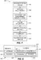
- method 900 may include specification and design (block 904) of aircraft 902 and material procurement (shown as block 906).
- component and subassembly manufacturing shown as block 908
- system integration shown as block 910
- aircraft 902 may go through certification and delivery (shown as block 912) to be placed in service (shown as block 914).
- routine maintenance and service shown as block 916). Routine maintenance and service may include modification, reconfiguration, refurbishment, etc. of one or more systems of aircraft 902.
- a system integrator may include, without limitation, any number of aircraft manufacturers and major-system subcontractors
- a third party may include, without limitation, any number of vendors, subcontractors, and suppliers
- an operator may be an airline, leasing company, military entity, service organization, and so on.
- aircraft 902 produced by method 900 may include airframe 918 with a plurality of high-level systems 920 and interior 922.
- high-level systems 920 include one or more of propulsion system 924, electrical system 926, hydraulic system 928, and environmental system 930. Any number of other systems may be included.
- propulsion system 924 one or more of propulsion system 924, electrical system 926, hydraulic system 928, and environmental system 930. Any number of other systems may be included.
- propulsion system 924 include one or more of propulsion system 924, electrical system 926, hydraulic system 928, and environmental system 930. Any number of other systems may be included.
- an aerospace example is shown, the principles disclosed herein may be applied to other industries, such as the automotive industry. Accordingly, in addition to aircraft 902, the principles disclosed herein may apply to other vehicles, e.g., land vehicles, marine vehicles, space vehicles, etc.
- Apparatus(es) and method(s) shown or described herein may be employed during any one or more of the stages of method 900.
- components or subassemblies corresponding to component and subassembly manufacturing (block 908) may be fabricated or manufactured in a manner similar to components or subassemblies produced while aircraft 902 is in service (block 914).
- one or more examples of the apparatus(es), method(s), or combination thereof may be utilized during production stages, illustrated by block 908 and block 910, for example, by substantially expediting assembly of or reducing the cost of aircraft 902.
- one or more examples of the apparatus or method realizations, or a combination thereof may be utilized, for example and without limitation, while aircraft 902 is in service (block 914) and/or during maintenance and service (block 916).
Landscapes
- Engineering & Computer Science (AREA)
- Aviation & Aerospace Engineering (AREA)
- Remote Sensing (AREA)
- Chemical & Material Sciences (AREA)
- Combustion & Propulsion (AREA)
- Life Sciences & Earth Sciences (AREA)
- Sustainable Development (AREA)
- Sustainable Energy (AREA)
- Transportation (AREA)
- Mechanical Engineering (AREA)
- Cooling, Air Intake And Gas Exhaust, And Fuel Tank Arrangements In Propulsion Units (AREA)
Applications Claiming Priority (2)
| Application Number | Priority Date | Filing Date | Title |
|---|---|---|---|
| US202163150320P | 2021-02-17 | 2021-02-17 | |
| US17/405,505 US11939086B2 (en) | 2021-02-17 | 2021-08-18 | Fuel tanks and reusable launch vehicles comprising these fuel tanks |
Publications (3)
| Publication Number | Publication Date |
|---|---|
| EP4046844A2 true EP4046844A2 (fr) | 2022-08-24 |
| EP4046844A3 EP4046844A3 (fr) | 2022-10-26 |
| EP4046844B1 EP4046844B1 (fr) | 2025-01-08 |
Family
ID=80683019
Family Applications (1)
| Application Number | Title | Priority Date | Filing Date |
|---|---|---|---|
| EP22156645.8A Active EP4046844B1 (fr) | 2021-02-17 | 2022-02-14 | Réservoirs de carburant et véhicules de lancement réutilisables comportant ces réservoirs de carburant |
Country Status (3)
| Country | Link |
|---|---|
| US (1) | US11939086B2 (fr) |
| EP (1) | EP4046844B1 (fr) |
| JP (1) | JP2022125995A (fr) |
Families Citing this family (2)
| Publication number | Priority date | Publication date | Assignee | Title |
|---|---|---|---|---|
| US12214911B2 (en) * | 2021-08-03 | 2025-02-04 | The Boeing Compnay | Load coupling attachment systems and methods |
| US20260021909A1 (en) * | 2024-07-19 | 2026-01-22 | Steamjet Space Systems, Ltd. | Spacecraft propellant tank and its application method |
Family Cites Families (19)
| Publication number | Priority date | Publication date | Assignee | Title |
|---|---|---|---|---|
| US4715399A (en) | 1984-10-29 | 1987-12-29 | Jaekle Jr Don E | Liquid-propellant management system for rockets and space vehicles |
| US4733531A (en) * | 1986-03-14 | 1988-03-29 | Lockheed Missiles & Space Company, Inc. | Liquid-propellant management system with capillary pumping vanes |
| US4768541A (en) * | 1986-11-03 | 1988-09-06 | Martin Marietta Corporation | Means of expelling parallel tanks to low residuals |
| US4901762A (en) * | 1988-10-03 | 1990-02-20 | Lockheed Missiles & Space Company, Inc. | Liquid-propellant management apparatus |
| JPH03224896A (ja) | 1990-01-30 | 1991-10-03 | Mitsubishi Heavy Ind Ltd | 液体ロケットの推進薬投棄装置 |
| US5279323A (en) | 1991-12-19 | 1994-01-18 | Lockheed Missiles & Space Company, Inc. | Liquid management apparatus for spacecraft |
| US5518140A (en) * | 1994-11-07 | 1996-05-21 | Cryenco, Inc. | Liquified gas storage tank overfill protection system and method |
| JP3646998B2 (ja) * | 1995-07-05 | 2005-05-11 | 株式会社アイ・エイチ・アイ・エアロスペース | 表面張力型推薬タンク |
| US6220287B1 (en) * | 2000-02-03 | 2001-04-24 | The Boeing Company | Baffle for suppressing slosh in a tank and a tank for incorporating same |
| US6591867B2 (en) | 2001-09-21 | 2003-07-15 | The Boeing Company | Variable-gravity anti-vortex and vapor-ingestion-suppression device |
| US6571624B1 (en) | 2001-12-03 | 2003-06-03 | The Boeing Company | Low gravity liquid level sensor rake |
| ITRM20050347A1 (it) * | 2005-06-30 | 2007-01-01 | Finmeccanica Spa | Liner plastico integrato per serbatoi di propellente per piattaforme e sistemi di trasporto spaziali. |
| DE102008017266B3 (de) * | 2008-04-04 | 2009-09-03 | WEW Westerwälder Eisenwerk GmbH | Schwallwand und Schwallwandanordnung für einen Behälter, insbesondere Tankcontainer |
| US9970389B2 (en) * | 2014-03-06 | 2018-05-15 | The Boeing Company | Antivortex device and method of assembling thereof |
| CN103950557B (zh) * | 2014-04-29 | 2016-05-04 | 北京控制工程研究所 | 一种用于空间飞行器中推进剂贮箱的蓄液器 |
| US20170122170A1 (en) * | 2015-10-30 | 2017-05-04 | Caterpillar Inc. | Filter System and Filtration Method for Fluid Reservoirs |
| US10065751B2 (en) * | 2016-04-05 | 2018-09-04 | Orbital Atk, Inc. | Liquid storage tanks and systems and propulsion systems for space vehicles and related methods |
| PT3318791T (pt) * | 2016-11-07 | 2021-03-02 | Ac Inox Gmbh | Tanque de carga de múltiplos lóbulos |
| US11384669B2 (en) * | 2019-07-12 | 2022-07-12 | Caterpillar Inc. | Integrated base filter for a DEF manifold |
-
2021
- 2021-08-18 US US17/405,505 patent/US11939086B2/en active Active
-
2022
- 2022-02-14 EP EP22156645.8A patent/EP4046844B1/fr active Active
- 2022-02-16 JP JP2022022173A patent/JP2022125995A/ja active Pending
Also Published As
| Publication number | Publication date |
|---|---|
| EP4046844A3 (fr) | 2022-10-26 |
| JP2022125995A (ja) | 2022-08-29 |
| US20220258874A1 (en) | 2022-08-18 |
| US11939086B2 (en) | 2024-03-26 |
| EP4046844B1 (fr) | 2025-01-08 |
Similar Documents
| Publication | Publication Date | Title |
|---|---|---|
| EP4046844A2 (fr) | Réservoirs de carburant et véhicules de lancement réutilisables comportant ces réservoirs de carburant | |
| AU2017204875B2 (en) | Wing and method of manufacturing | |
| US9096324B2 (en) | Joint assembly to form a sealed flow conduit | |
| JP2023175939A (ja) | 航空宇宙ビークルのための前縁システム及び方法 | |
| EP3705394B1 (fr) | Enceinte d'unité de puissance auxiliaire et son procédé de fabrication | |
| US8800917B2 (en) | Aircraft engine pylon AFT aerodynamic fairing | |
| BR102018006195B1 (pt) | Sistema para contenção de pá de ventoinha | |
| Dorsey et al. | Metallic thermal protection system requirements, environments, and integrated concepts | |
| US11414205B2 (en) | Fuel containment system | |
| EP4124564B1 (fr) | Ensembles raidisseurs en profilé chapeau pour un aéronef et leurs procédés de fabrication | |
| EP4545419A1 (fr) | Réservoir de stockage d'hydrogène pour aéronef à hydrogène | |
| Daniel et al. | Advanced composite technology in reusable launch vehicle (RLV) | |
| US20250383051A1 (en) | Cryogenic Tank Support System | |
| Saraçyakupoğlu | Manufacturing and Maintenance Operations for Bladder-Type Aircraft Fuel Tanks | |
| Tsuyuki et al. | The Hardware Challenges for the Mars Exploration Rover Heat Rejection System | |
| Lange et al. | Status of Flap Development for Future Re-Entry Vehicles (Pre-X) | |
| JP2023129337A (ja) | 輸送体パネルアセンブリ及びパネルアセンブリの方法 | |
| Katzberg et al. | Aerobrake assembly with minimum Space Station accommodation | |
| Bernstein et al. | Effect on Structures of Rapidly Changing Environmental Conditions-Launch to Orbit to Entry | |
| Kester et al. | Design of the EXPERT Re-entry Vehicle Metallic Thermal Protection System | |
| van den Abeelen | Staying Cool: The Thermal Protection System | |
| HAUSER, III et al. | Optimization of Boeing IUS ASE design using sensitivity analysis | |
| Brooks | Structural Material Requirements for Manned Space Vehicles |
Legal Events
| Date | Code | Title | Description |
|---|---|---|---|
| PUAI | Public reference made under article 153(3) epc to a published international application that has entered the european phase |
Free format text: ORIGINAL CODE: 0009012 |
|
| STAA | Information on the status of an ep patent application or granted ep patent |
Free format text: STATUS: THE APPLICATION HAS BEEN PUBLISHED |
|
| AK | Designated contracting states |
Kind code of ref document: A2 Designated state(s): AL AT BE BG CH CY CZ DE DK EE ES FI FR GB GR HR HU IE IS IT LI LT LU LV MC MK MT NL NO PL PT RO RS SE SI SK SM TR |
|
| PUAL | Search report despatched |
Free format text: ORIGINAL CODE: 0009013 |
|
| AK | Designated contracting states |
Kind code of ref document: A3 Designated state(s): AL AT BE BG CH CY CZ DE DK EE ES FI FR GB GR HR HU IE IS IT LI LT LU LV MC MK MT NL NO PL PT RO RS SE SI SK SM TR |
|
| RIC1 | Information provided on ipc code assigned before grant |
Ipc: B60K 15/03 20060101AFI20220922BHEP |
|
| RAP3 | Party data changed (applicant data changed or rights of an application transferred) |
Owner name: THE BOEING COMPANY |
|
| STAA | Information on the status of an ep patent application or granted ep patent |
Free format text: STATUS: REQUEST FOR EXAMINATION WAS MADE |
|
| 17P | Request for examination filed |
Effective date: 20230417 |
|
| RBV | Designated contracting states (corrected) |
Designated state(s): AL AT BE BG CH CY CZ DE DK EE ES FI FR GB GR HR HU IE IS IT LI LT LU LV MC MK MT NL NO PL PT RO RS SE SI SK SM TR |
|
| GRAP | Despatch of communication of intention to grant a patent |
Free format text: ORIGINAL CODE: EPIDOSNIGR1 |
|
| STAA | Information on the status of an ep patent application or granted ep patent |
Free format text: STATUS: GRANT OF PATENT IS INTENDED |
|
| INTG | Intention to grant announced |
Effective date: 20240806 |
|
| GRAS | Grant fee paid |
Free format text: ORIGINAL CODE: EPIDOSNIGR3 |
|
| GRAA | (expected) grant |
Free format text: ORIGINAL CODE: 0009210 |
|
| STAA | Information on the status of an ep patent application or granted ep patent |
Free format text: STATUS: THE PATENT HAS BEEN GRANTED |
|
| P01 | Opt-out of the competence of the unified patent court (upc) registered |
Free format text: CASE NUMBER: APP_60601/2024 Effective date: 20241111 |
|
| AK | Designated contracting states |
Kind code of ref document: B1 Designated state(s): AL AT BE BG CH CY CZ DE DK EE ES FI FR GB GR HR HU IE IS IT LI LT LU LV MC MK MT NL NO PL PT RO RS SE SI SK SM TR |
|
| REG | Reference to a national code |
Ref country code: GB Ref legal event code: FG4D |
|
| REG | Reference to a national code |
Ref country code: CH Ref legal event code: EP |
|
| REG | Reference to a national code |
Ref country code: DE Ref legal event code: R096 Ref document number: 602022009452 Country of ref document: DE |
|
| REG | Reference to a national code |
Ref country code: IE Ref legal event code: FG4D |
|
| PGFP | Annual fee paid to national office [announced via postgrant information from national office to epo] |
Ref country code: AT Payment date: 20250417 Year of fee payment: 4 |
|
| REG | Reference to a national code |
Ref country code: LT Ref legal event code: MG9D |
|
| REG | Reference to a national code |
Ref country code: NL Ref legal event code: MP Effective date: 20250108 |
|
| REG | Reference to a national code |
Ref country code: AT Ref legal event code: MK05 Ref document number: 1758118 Country of ref document: AT Kind code of ref document: T Effective date: 20250108 |
|
| PG25 | Lapsed in a contracting state [announced via postgrant information from national office to epo] |
Ref country code: NL Free format text: LAPSE BECAUSE OF FAILURE TO SUBMIT A TRANSLATION OF THE DESCRIPTION OR TO PAY THE FEE WITHIN THE PRESCRIBED TIME-LIMIT Effective date: 20250108 |
|
| PG25 | Lapsed in a contracting state [announced via postgrant information from national office to epo] |
Ref country code: RS Free format text: LAPSE BECAUSE OF FAILURE TO SUBMIT A TRANSLATION OF THE DESCRIPTION OR TO PAY THE FEE WITHIN THE PRESCRIBED TIME-LIMIT Effective date: 20250408 |
|
| PG25 | Lapsed in a contracting state [announced via postgrant information from national office to epo] |
Ref country code: PL Free format text: LAPSE BECAUSE OF FAILURE TO SUBMIT A TRANSLATION OF THE DESCRIPTION OR TO PAY THE FEE WITHIN THE PRESCRIBED TIME-LIMIT Effective date: 20250108 |
|
| PG25 | Lapsed in a contracting state [announced via postgrant information from national office to epo] |
Ref country code: ES Free format text: LAPSE BECAUSE OF FAILURE TO SUBMIT A TRANSLATION OF THE DESCRIPTION OR TO PAY THE FEE WITHIN THE PRESCRIBED TIME-LIMIT Effective date: 20250108 |
|
| PG25 | Lapsed in a contracting state [announced via postgrant information from national office to epo] |
Ref country code: NO Free format text: LAPSE BECAUSE OF FAILURE TO SUBMIT A TRANSLATION OF THE DESCRIPTION OR TO PAY THE FEE WITHIN THE PRESCRIBED TIME-LIMIT Effective date: 20250408 Ref country code: IS Free format text: LAPSE BECAUSE OF FAILURE TO SUBMIT A TRANSLATION OF THE DESCRIPTION OR TO PAY THE FEE WITHIN THE PRESCRIBED TIME-LIMIT Effective date: 20250508 |
|
| PG25 | Lapsed in a contracting state [announced via postgrant information from national office to epo] |
Ref country code: HR Free format text: LAPSE BECAUSE OF FAILURE TO SUBMIT A TRANSLATION OF THE DESCRIPTION OR TO PAY THE FEE WITHIN THE PRESCRIBED TIME-LIMIT Effective date: 20250108 |
|
| PG25 | Lapsed in a contracting state [announced via postgrant information from national office to epo] |
Ref country code: PT Free format text: LAPSE BECAUSE OF FAILURE TO SUBMIT A TRANSLATION OF THE DESCRIPTION OR TO PAY THE FEE WITHIN THE PRESCRIBED TIME-LIMIT Effective date: 20250508 Ref country code: LV Free format text: LAPSE BECAUSE OF FAILURE TO SUBMIT A TRANSLATION OF THE DESCRIPTION OR TO PAY THE FEE WITHIN THE PRESCRIBED TIME-LIMIT Effective date: 20250108 |
|
| PG25 | Lapsed in a contracting state [announced via postgrant information from national office to epo] |
Ref country code: GR Free format text: LAPSE BECAUSE OF FAILURE TO SUBMIT A TRANSLATION OF THE DESCRIPTION OR TO PAY THE FEE WITHIN THE PRESCRIBED TIME-LIMIT Effective date: 20250409 Ref country code: BG Free format text: LAPSE BECAUSE OF FAILURE TO SUBMIT A TRANSLATION OF THE DESCRIPTION OR TO PAY THE FEE WITHIN THE PRESCRIBED TIME-LIMIT Effective date: 20250108 |
|
| PG25 | Lapsed in a contracting state [announced via postgrant information from national office to epo] |
Ref country code: AT Free format text: LAPSE BECAUSE OF FAILURE TO SUBMIT A TRANSLATION OF THE DESCRIPTION OR TO PAY THE FEE WITHIN THE PRESCRIBED TIME-LIMIT Effective date: 20250108 |
|
| PG25 | Lapsed in a contracting state [announced via postgrant information from national office to epo] |
Ref country code: SE Free format text: LAPSE BECAUSE OF FAILURE TO SUBMIT A TRANSLATION OF THE DESCRIPTION OR TO PAY THE FEE WITHIN THE PRESCRIBED TIME-LIMIT Effective date: 20250108 |
|
| REG | Reference to a national code |
Ref country code: CH Ref legal event code: PL |
|
| PG25 | Lapsed in a contracting state [announced via postgrant information from national office to epo] |
Ref country code: SM Free format text: LAPSE BECAUSE OF FAILURE TO SUBMIT A TRANSLATION OF THE DESCRIPTION OR TO PAY THE FEE WITHIN THE PRESCRIBED TIME-LIMIT Effective date: 20250108 |
|
| REG | Reference to a national code |
Ref country code: DE Ref legal event code: R097 Ref document number: 602022009452 Country of ref document: DE |
|
| PG25 | Lapsed in a contracting state [announced via postgrant information from national office to epo] |
Ref country code: DK Free format text: LAPSE BECAUSE OF FAILURE TO SUBMIT A TRANSLATION OF THE DESCRIPTION OR TO PAY THE FEE WITHIN THE PRESCRIBED TIME-LIMIT Effective date: 20250108 |
|
| PG25 | Lapsed in a contracting state [announced via postgrant information from national office to epo] |
Ref country code: MC Free format text: LAPSE BECAUSE OF FAILURE TO SUBMIT A TRANSLATION OF THE DESCRIPTION OR TO PAY THE FEE WITHIN THE PRESCRIBED TIME-LIMIT Effective date: 20250108 |
|
| PG25 | Lapsed in a contracting state [announced via postgrant information from national office to epo] |
Ref country code: LU Free format text: LAPSE BECAUSE OF NON-PAYMENT OF DUE FEES Effective date: 20250214 |
|
| PG25 | Lapsed in a contracting state [announced via postgrant information from national office to epo] |
Ref country code: CH Free format text: LAPSE BECAUSE OF NON-PAYMENT OF DUE FEES Effective date: 20250228 |
|
| PG25 | Lapsed in a contracting state [announced via postgrant information from national office to epo] |
Ref country code: CZ Free format text: LAPSE BECAUSE OF FAILURE TO SUBMIT A TRANSLATION OF THE DESCRIPTION OR TO PAY THE FEE WITHIN THE PRESCRIBED TIME-LIMIT Effective date: 20250108 Ref country code: EE Free format text: LAPSE BECAUSE OF FAILURE TO SUBMIT A TRANSLATION OF THE DESCRIPTION OR TO PAY THE FEE WITHIN THE PRESCRIBED TIME-LIMIT Effective date: 20250108 |
|
| PG25 | Lapsed in a contracting state [announced via postgrant information from national office to epo] |
Ref country code: RO Free format text: LAPSE BECAUSE OF FAILURE TO SUBMIT A TRANSLATION OF THE DESCRIPTION OR TO PAY THE FEE WITHIN THE PRESCRIBED TIME-LIMIT Effective date: 20250108 |
|
| PG25 | Lapsed in a contracting state [announced via postgrant information from national office to epo] |
Ref country code: SK Free format text: LAPSE BECAUSE OF FAILURE TO SUBMIT A TRANSLATION OF THE DESCRIPTION OR TO PAY THE FEE WITHIN THE PRESCRIBED TIME-LIMIT Effective date: 20250108 |
|
| PLBE | No opposition filed within time limit |
Free format text: ORIGINAL CODE: 0009261 |
|
| STAA | Information on the status of an ep patent application or granted ep patent |
Free format text: STATUS: NO OPPOSITION FILED WITHIN TIME LIMIT |
|
| REG | Reference to a national code |
Ref country code: BE Ref legal event code: MM Effective date: 20250228 |
|
| 26N | No opposition filed |
Effective date: 20251009 |
|
| PG25 | Lapsed in a contracting state [announced via postgrant information from national office to epo] |
Ref country code: BE Free format text: LAPSE BECAUSE OF NON-PAYMENT OF DUE FEES Effective date: 20250228 |
|
| PG25 | Lapsed in a contracting state [announced via postgrant information from national office to epo] |
Ref country code: IE Free format text: LAPSE BECAUSE OF NON-PAYMENT OF DUE FEES Effective date: 20250214 |
|
| PG25 | Lapsed in a contracting state [announced via postgrant information from national office to epo] |
Ref country code: IT Free format text: LAPSE BECAUSE OF FAILURE TO SUBMIT A TRANSLATION OF THE DESCRIPTION OR TO PAY THE FEE WITHIN THE PRESCRIBED TIME-LIMIT Effective date: 20250108 |
|
| PGFP | Annual fee paid to national office [announced via postgrant information from national office to epo] |
Ref country code: GB Payment date: 20260227 Year of fee payment: 5 |
|
| PGFP | Annual fee paid to national office [announced via postgrant information from national office to epo] |
Ref country code: DE Payment date: 20260227 Year of fee payment: 5 |
|
| PGFP | Annual fee paid to national office [announced via postgrant information from national office to epo] |
Ref country code: FR Payment date: 20260225 Year of fee payment: 5 |