EP4046743A1 - Wire rod for welding rods and method for manufacturing same - Google Patents
Wire rod for welding rods and method for manufacturing same Download PDFInfo
- Publication number
- EP4046743A1 EP4046743A1 EP20877049.5A EP20877049A EP4046743A1 EP 4046743 A1 EP4046743 A1 EP 4046743A1 EP 20877049 A EP20877049 A EP 20877049A EP 4046743 A1 EP4046743 A1 EP 4046743A1
- Authority
- EP
- European Patent Office
- Prior art keywords
- wire rod
- less
- welding
- welding rods
- room temperature
- Prior art date
- Legal status (The legal status is an assumption and is not a legal conclusion. Google has not performed a legal analysis and makes no representation as to the accuracy of the status listed.)
- Pending
Links
Images

Classifications
-
- B—PERFORMING OPERATIONS; TRANSPORTING
- B23—MACHINE TOOLS; METAL-WORKING NOT OTHERWISE PROVIDED FOR
- B23K—SOLDERING OR UNSOLDERING; WELDING; CLADDING OR PLATING BY SOLDERING OR WELDING; CUTTING BY APPLYING HEAT LOCALLY, e.g. FLAME CUTTING; WORKING BY LASER BEAM
- B23K35/00—Rods, electrodes, materials, or media, for use in soldering, welding, or cutting
- B23K35/02—Rods, electrodes, materials, or media, for use in soldering, welding, or cutting characterised by mechanical features, e.g. shape
- B23K35/0255—Rods, electrodes, materials, or media, for use in soldering, welding, or cutting characterised by mechanical features, e.g. shape for use in welding
- B23K35/0261—Rods, electrodes or wires
-
- B—PERFORMING OPERATIONS; TRANSPORTING
- B21—MECHANICAL METAL-WORKING WITHOUT ESSENTIALLY REMOVING MATERIAL; PUNCHING METAL
- B21B—ROLLING OF METAL
- B21B1/00—Metal-rolling methods or mills for making semi-finished products of solid or profiled cross-section; Sequence of operations in milling trains; Layout of rolling-mill plant, e.g. grouping of stands; Succession of passes or of sectional pass alternations
- B21B1/16—Metal-rolling methods or mills for making semi-finished products of solid or profiled cross-section; Sequence of operations in milling trains; Layout of rolling-mill plant, e.g. grouping of stands; Succession of passes or of sectional pass alternations for rolling wire rods, bars, merchant bars, rounds wire or material of like small cross-section
-
- B—PERFORMING OPERATIONS; TRANSPORTING
- B23—MACHINE TOOLS; METAL-WORKING NOT OTHERWISE PROVIDED FOR
- B23K—SOLDERING OR UNSOLDERING; WELDING; CLADDING OR PLATING BY SOLDERING OR WELDING; CUTTING BY APPLYING HEAT LOCALLY, e.g. FLAME CUTTING; WORKING BY LASER BEAM
- B23K35/00—Rods, electrodes, materials, or media, for use in soldering, welding, or cutting
- B23K35/22—Rods, electrodes, materials, or media, for use in soldering, welding, or cutting characterised by the composition or nature of the material
- B23K35/24—Selection of soldering or welding materials proper
- B23K35/30—Selection of soldering or welding materials proper with the principal constituent melting at less than 1550°C
- B23K35/3053—Fe as the principal constituent
-
- B—PERFORMING OPERATIONS; TRANSPORTING
- B23—MACHINE TOOLS; METAL-WORKING NOT OTHERWISE PROVIDED FOR
- B23K—SOLDERING OR UNSOLDERING; WELDING; CLADDING OR PLATING BY SOLDERING OR WELDING; CUTTING BY APPLYING HEAT LOCALLY, e.g. FLAME CUTTING; WORKING BY LASER BEAM
- B23K35/00—Rods, electrodes, materials, or media, for use in soldering, welding, or cutting
- B23K35/22—Rods, electrodes, materials, or media, for use in soldering, welding, or cutting characterised by the composition or nature of the material
- B23K35/24—Selection of soldering or welding materials proper
- B23K35/30—Selection of soldering or welding materials proper with the principal constituent melting at less than 1550°C
- B23K35/3053—Fe as the principal constituent
- B23K35/3066—Fe as the principal constituent with Ni as next major constituent
-
- B—PERFORMING OPERATIONS; TRANSPORTING
- B23—MACHINE TOOLS; METAL-WORKING NOT OTHERWISE PROVIDED FOR
- B23K—SOLDERING OR UNSOLDERING; WELDING; CLADDING OR PLATING BY SOLDERING OR WELDING; CUTTING BY APPLYING HEAT LOCALLY, e.g. FLAME CUTTING; WORKING BY LASER BEAM
- B23K35/00—Rods, electrodes, materials, or media, for use in soldering, welding, or cutting
- B23K35/22—Rods, electrodes, materials, or media, for use in soldering, welding, or cutting characterised by the composition or nature of the material
- B23K35/24—Selection of soldering or welding materials proper
- B23K35/30—Selection of soldering or welding materials proper with the principal constituent melting at less than 1550°C
- B23K35/3053—Fe as the principal constituent
- B23K35/3073—Fe as the principal constituent with Mn as next major constituent
-
- B—PERFORMING OPERATIONS; TRANSPORTING
- B23—MACHINE TOOLS; METAL-WORKING NOT OTHERWISE PROVIDED FOR
- B23K—SOLDERING OR UNSOLDERING; WELDING; CLADDING OR PLATING BY SOLDERING OR WELDING; CUTTING BY APPLYING HEAT LOCALLY, e.g. FLAME CUTTING; WORKING BY LASER BEAM
- B23K35/00—Rods, electrodes, materials, or media, for use in soldering, welding, or cutting
- B23K35/40—Making wire or rods for soldering or welding
-
- C—CHEMISTRY; METALLURGY
- C21—METALLURGY OF IRON
- C21D—MODIFYING THE PHYSICAL STRUCTURE OF FERROUS METALS; GENERAL DEVICES FOR HEAT TREATMENT OF FERROUS OR NON-FERROUS METALS OR ALLOYS; MAKING METAL MALLEABLE, e.g. BY DECARBURISATION OR TEMPERING
- C21D6/00—Heat treatment of ferrous alloys
- C21D6/005—Heat treatment of ferrous alloys containing Mn
-
- C—CHEMISTRY; METALLURGY
- C21—METALLURGY OF IRON
- C21D—MODIFYING THE PHYSICAL STRUCTURE OF FERROUS METALS; GENERAL DEVICES FOR HEAT TREATMENT OF FERROUS OR NON-FERROUS METALS OR ALLOYS; MAKING METAL MALLEABLE, e.g. BY DECARBURISATION OR TEMPERING
- C21D8/00—Modifying the physical properties of ferrous metals or ferrous alloys by deformation combined with, or followed by, heat treatment
- C21D8/06—Modifying the physical properties of ferrous metals or ferrous alloys by deformation combined with, or followed by, heat treatment during manufacturing of rods or wires
-
- C—CHEMISTRY; METALLURGY
- C21—METALLURGY OF IRON
- C21D—MODIFYING THE PHYSICAL STRUCTURE OF FERROUS METALS; GENERAL DEVICES FOR HEAT TREATMENT OF FERROUS OR NON-FERROUS METALS OR ALLOYS; MAKING METAL MALLEABLE, e.g. BY DECARBURISATION OR TEMPERING
- C21D9/00—Heat treatment, e.g. annealing, hardening, quenching or tempering, adapted for particular articles; Furnaces therefor
- C21D9/0075—Heat treatment, e.g. annealing, hardening, quenching or tempering, adapted for particular articles; Furnaces therefor for rods of limited length
-
- C—CHEMISTRY; METALLURGY
- C21—METALLURGY OF IRON
- C21D—MODIFYING THE PHYSICAL STRUCTURE OF FERROUS METALS; GENERAL DEVICES FOR HEAT TREATMENT OF FERROUS OR NON-FERROUS METALS OR ALLOYS; MAKING METAL MALLEABLE, e.g. BY DECARBURISATION OR TEMPERING
- C21D9/00—Heat treatment, e.g. annealing, hardening, quenching or tempering, adapted for particular articles; Furnaces therefor
- C21D9/52—Heat treatment, e.g. annealing, hardening, quenching or tempering, adapted for particular articles; Furnaces therefor for wires; for strips ; for rods of unlimited length
- C21D9/525—Heat treatment, e.g. annealing, hardening, quenching or tempering, adapted for particular articles; Furnaces therefor for wires; for strips ; for rods of unlimited length for wire, for rods
-
- C—CHEMISTRY; METALLURGY
- C22—METALLURGY; FERROUS OR NON-FERROUS ALLOYS; TREATMENT OF ALLOYS OR NON-FERROUS METALS
- C22C—ALLOYS
- C22C38/00—Ferrous alloys, e.g. steel alloys
- C22C38/001—Ferrous alloys, e.g. steel alloys containing N
-
- C—CHEMISTRY; METALLURGY
- C22—METALLURGY; FERROUS OR NON-FERROUS ALLOYS; TREATMENT OF ALLOYS OR NON-FERROUS METALS
- C22C—ALLOYS
- C22C38/00—Ferrous alloys, e.g. steel alloys
- C22C38/02—Ferrous alloys, e.g. steel alloys containing silicon
-
- C—CHEMISTRY; METALLURGY
- C22—METALLURGY; FERROUS OR NON-FERROUS ALLOYS; TREATMENT OF ALLOYS OR NON-FERROUS METALS
- C22C—ALLOYS
- C22C38/00—Ferrous alloys, e.g. steel alloys
- C22C38/04—Ferrous alloys, e.g. steel alloys containing manganese
-
- C—CHEMISTRY; METALLURGY
- C22—METALLURGY; FERROUS OR NON-FERROUS ALLOYS; TREATMENT OF ALLOYS OR NON-FERROUS METALS
- C22C—ALLOYS
- C22C38/00—Ferrous alloys, e.g. steel alloys
- C22C38/12—Ferrous alloys, e.g. steel alloys containing tungsten, tantalum, molybdenum, vanadium, or niobium
-
- C—CHEMISTRY; METALLURGY
- C22—METALLURGY; FERROUS OR NON-FERROUS ALLOYS; TREATMENT OF ALLOYS OR NON-FERROUS METALS
- C22C—ALLOYS
- C22C38/00—Ferrous alloys, e.g. steel alloys
- C22C38/18—Ferrous alloys, e.g. steel alloys containing chromium
- C22C38/22—Ferrous alloys, e.g. steel alloys containing chromium with molybdenum or tungsten
-
- C—CHEMISTRY; METALLURGY
- C22—METALLURGY; FERROUS OR NON-FERROUS ALLOYS; TREATMENT OF ALLOYS OR NON-FERROUS METALS
- C22C—ALLOYS
- C22C38/00—Ferrous alloys, e.g. steel alloys
- C22C38/18—Ferrous alloys, e.g. steel alloys containing chromium
- C22C38/38—Ferrous alloys, e.g. steel alloys containing chromium with more than 1.5% by weight of manganese
-
- C—CHEMISTRY; METALLURGY
- C22—METALLURGY; FERROUS OR NON-FERROUS ALLOYS; TREATMENT OF ALLOYS OR NON-FERROUS METALS
- C22C—ALLOYS
- C22C38/00—Ferrous alloys, e.g. steel alloys
- C22C38/18—Ferrous alloys, e.g. steel alloys containing chromium
- C22C38/40—Ferrous alloys, e.g. steel alloys containing chromium with nickel
- C22C38/44—Ferrous alloys, e.g. steel alloys containing chromium with nickel with molybdenum or tungsten
-
- C—CHEMISTRY; METALLURGY
- C22—METALLURGY; FERROUS OR NON-FERROUS ALLOYS; TREATMENT OF ALLOYS OR NON-FERROUS METALS
- C22C—ALLOYS
- C22C38/00—Ferrous alloys, e.g. steel alloys
- C22C38/18—Ferrous alloys, e.g. steel alloys containing chromium
- C22C38/40—Ferrous alloys, e.g. steel alloys containing chromium with nickel
- C22C38/46—Ferrous alloys, e.g. steel alloys containing chromium with nickel with vanadium
-
- C—CHEMISTRY; METALLURGY
- C22—METALLURGY; FERROUS OR NON-FERROUS ALLOYS; TREATMENT OF ALLOYS OR NON-FERROUS METALS
- C22C—ALLOYS
- C22C38/00—Ferrous alloys, e.g. steel alloys
- C22C38/18—Ferrous alloys, e.g. steel alloys containing chromium
- C22C38/40—Ferrous alloys, e.g. steel alloys containing chromium with nickel
- C22C38/58—Ferrous alloys, e.g. steel alloys containing chromium with nickel with more than 1.5% by weight of manganese
-
- C—CHEMISTRY; METALLURGY
- C21—METALLURGY OF IRON
- C21D—MODIFYING THE PHYSICAL STRUCTURE OF FERROUS METALS; GENERAL DEVICES FOR HEAT TREATMENT OF FERROUS OR NON-FERROUS METALS OR ALLOYS; MAKING METAL MALLEABLE, e.g. BY DECARBURISATION OR TEMPERING
- C21D2211/00—Microstructure comprising significant phases
- C21D2211/001—Austenite
Definitions
- the present disclosure relates to a wire rod appropriate for a material for welding rods, and particularly, to a wire rod for welding rods having excellent strength at room temperature and excellent rod drawing properties and a method for manufacturing the same.
- welding rods mainly use a wire rod as a material thereof, and the wire rod is manufactured by hot rolling and then rod drawing at room temperature.
- the wire rod is drawn to a specific diameter and is produced as a material for submerged arc welding, shielded metal arc welding, gas metal arc welding, gas tungsten arc welding, and the like and applied.
- a weld zone which is formed by performing welding of a base material by the welding method using the wire rod for welding rods is required to have high impact toughness, strength at room temperature, and the like, for the reason such as stability of a structure.
- a wire rod including 50 wt% or more of nickel (Ni) with a total of more than 30 wt% of chromium (Cr) and molybdenum (Mo) for improving strength has been applied.
- Ni nickel
- Cr chromium
- Mo molybdenum
- An aspect of the present disclosure is to provide a material for welding materials, in particular, a wire rod appropriate for a material for welding rods, which has excellent rod drawing properties, high tensile strength at room temperature of a weld zone after welding, and excellent cryogenic impact toughness.
- An object of the present disclosure is not limited to the above description.
- the object of the present disclosure will be understood from the entire content of the present specification, and a person skilled in the art to which the present disclosure pertains will understand an additional object of the present disclosure without difficulty.
- a wire rod for welding rods includes, by weight: 0.05 to 0.8% of carbon (C), 18 to 31% of manganese (Mn), 0.05 to 0.7% of silicon (Si), 0.15% or less of nitrogen (N), 0.02% or less of phosphorus (P), and 0.01% or less of sulfur (S), with a balance of Fe and unavoidable impurities, wherein the following Relation 1 is satisfied: Mn + 1.6 Ni + 15 C + N ⁇ 24 wherein each element refers to a content by weight of the element.
- a method for manufacturing a wire rod for welding rods includes: preparing a steel workpiece or an ingot satisfying the alloy composition described above and Relation 1; heat treating the steel workpiece or the ingot in a temperature range of 800 to 1250°C to manufacture a billet; and subjecting the billet to wire rod rolling in a temperature range of 800 to 1250°C to manufacture a wire rod.
- a wire rod having the physical properties required as a material for welding rods may be provided at low cost.
- the present disclosure may provide a wire rod which has excellent strength at room temperature and excellent cryogenic impact toughness of a weld zone after welding and has excellent rod drawing properties of a tensile strength of 850 MPa or less at room temperature and an elongation of 30% or more, though the use of expensive elements which have been mainly used for manufacturing a conventional wire rod for welding rods are greatly decreased.
- the wire rod of the present disclosure may be favorably applied as a wire rod for welding rods.
- the present inventors confirmed a limitation of conventional materials used as a welding rod, and intensively studied in order to develop a material which allows the physical property values required for a weld zone to be secured at low cost and has excellent rod drawing properties.
- the wire rod for welding rods is manufactured by rod drawing at room temperature of a wire rod obtained by hot rolling, it requires to have excellent processability at room temperature, and for this, the present disclosure has a technical significance in optimizing a component system by properly using elements stable at room temperature.
- processability at room temperature depends on austenite stability of an alloy element and a processing type at the time of rod drawing, and the present disclosure is characterized in that carbon (C), nickel (Ni), manganese (Mn), nitrogen (N), and the like as appropriate elements therefor are controlled to appropriate contents, while a content relationship among them is suggested.
- the wire rod for welding rods may include, by weight: 0.05 to 0.8% of carbon (C), 18 to 31% of manganese (Mn), 0.05 to 0.7% of silicon (Si), 0.15% or less of nitrogen (N), 0.02% or less of phosphorus (P), and 0.01% or less of sulfur (S).
- the content of each element is by weight and the ratio of the structure is by area.
- Carbon (C) is an austenite forming element, and is favorable for improving impact toughness of a weld zone in a cryogenic environment and improving strength at room temperature.
- C may be included at 0.05 to 0.8%, and more favorably at 0.78% or less.
- Manganese (Mn) is an element forming austenite, which is similar to C, and is an element favorable for improving impact toughness at cryogenic temperature.
- Mn may be included at 18 to 31%.
- Si is an element added for improving flowability of welding materials at the time of welding, and is favorable to a deoxidation effect.
- Si may be included at 0.05% or more.
- an eutectic compound is excessively precipitated and crack resistance is deteriorated.
- Si may be included at 0.05 to 0.7%.
- N is an austenite forming element which is similar to C, and is effective in improving impact toughness of a weld zone in a cryogenic environment and improve strength at room temperature.
- N may be further added in terms of further promoting the effect of strength improvement by C.
- N When the content of N is more than 0.15%, occurrences of cracks at a high temperature and pores are promoted during welding, and thus, considering the fact, N may be included at 0.15% or less. However, 0% may be fine.
- Phosphorus (P) and sulfur (S) easily produce a low-melting point compound by addition in a small amount to lower the melting point of a material, thereby increasing cracking susceptibility at a high temperature. Thus, it is preferred that the contents of P and S are greatly decreased as much as possible.
- each content may be inevitably added during the manufacturing process, and when each content is 0.02% or less and 0.01% or less, the physical properties of the wire rod are not influenced, and thus, each content may be limited as such.
- the wire rod of the present disclosure may further include elements favorable for forming the structure and securing the physical properties, in addition to the alloy composition described above.
- the wire rod of the present disclosure may further include one or more of nickel (Ni), chromium (Cr), molybdenum (Mo), and vanadium (V), as described later.
- Ni nickel
- Cr chromium
- Mo molybdenum
- V vanadium
- Nickel (Ni) is an austenite forming element, and may be added for forming the structure of the wire rod completely into an austenite structure to secure cryogenic toughness.
- Ni When the content of Ni is more than 8%, strength at room temperature is lowered, which is thus not preferred. Therefore, Ni may be included at 8% or less.
- Ni may not be included.
- Chromium (Cr) is a ferrite forming element, and promotes production of ferrite to serve to expand an austenite area ( FIG. 1 ) .
- the higher content of Cr is favorable for improving strength at room temperature, but when Cr is added more than a specific content, Cr tends to be bonded to C to produce a carbide to cause cryogenic impact toughness to be lowered.
- Cr when Cr is added, Cr may be included up to 3.5% for improving strength at room temperature and austenite stability.
- Molybdenum (Mo) has a better effect of improving strength at room temperature than Cr, and has a lower bonding strength to C than Cr, and thus, when added, the cryogenic impact toughness is less lowered than Cr.
- Mo is an expensive element, and when added at a specific amount or more, manufacturing costs are greatly increased, and deterioration of cryogenic impact toughness may be caused.
- Mo when Mo is added, considering the manufacturing costs and strength improvement, Mo may be included up to 3.5%.
- Vanadium (V) has a better effect of improving strength at room temperature than Cr and Mo.
- the price of V is 10 times or more higher than the price of Cr and 4 times or more higher than the price of Mo, and thus, V has a limitation in obtaining a low cost material.
- V when V is added, considering the manufacturing costs, V may be included up to 0.3%.
- the remaining component of the present disclosure is iron (Fe) .
- Fe iron
- the component since in the common manufacturing process, unintended impurities may be inevitably incorporated from raw materials or the surrounding environment, the component may not be excluded. Since these impurities are known to those skilled in the common manufacturing process, the entire contents thereof are not particularly mentioned in the present specification.
- the wire rod of the present disclosure having the alloy composition described above satisfies the following component relation within the content range.
- austenite stability of a steel is calculated by a Schaeffler diagram, as values of a Ni equivalent and a Cr equivalent.
- the equations for the Ni equivalent and the Cr equivalent are known as [Ni + 0.5Mn + 30(C+N)] and [Cr + 2.5Si + 1.8Mo].
- the wire rod of the present disclosure is completely different from the conventional material including large amounts of Ni, Cr, and the like and is formed of a novel component composition, the relationship among the alloy elements was intended to be redefined.
- the present disclosure defines [Relation 1] and [Relation 2] described above and provides a wire rod satisfying the same, thereby providing a wire rod for welding rods which has a somewhat low tensile strength at room temperature in the state of a wire rod to have excellent rod drawing properties, has a target level or more of tensile strength at room temperature after welding, and may form a weld zone having physical properties required in a cryogenic environment.
- the structure of a wire rod manufactured by satisfying the value of [Relation 1] in the alloy component system suggested in the present disclosure may be formed into stable austenite, whereby a strength of 850 MPa or less and an elongation of 30% or more are illustrated, and thus, rod drawing properties are excellent and austenite may be stably secured even in a weld zone after welding. That is, in the present disclosure, a wire rod in which both the structure of the wire rod and the structure of the weld joint after welding using the wire rod have the austenite structure may be provided.
- the present disclosure may obtain an effect of securing a cryogenic (-197°C) impact toughness of a weld zone formed at the time of welding of 27 J or more, therefrom.
- the present disclosure satisfies [Relation 2] within the limited contents in using Ni, Cr, Mo, and V for sufficiently improving the strength at room temperature of the wire rod, thereby securing strength at room temperature while structurally maintaining an austenite phase after welding.
- the present disclosure satisfies the alloy component system and Relations 1 and 2 as suggested, whereby the microstructure of the weld zone after welding is formed of an austenite single phase structure to have excellent cryogenic toughness and provide a wire rod having excellent room temperature strength properties.
- the wire rod of the present disclosure has an austenite structure at room temperature to show a tensile strength of 850 MPa or less and an elongation of 30% or more, which correspond to the mechanical properties allowing rod drawing processing for being manufactured into a welding rod, and thus, the wire rod is favorable to processing at room temperature.
- a steel workpiece or an ingot satisfying the alloy composition and the component relation (Relations 1 and 2) described above is prepared, and then is heat treated in a temperature range of 800 to 1250°C, thereby manufacturing a billet.
- the heat-treated billet may be subjected to wire rod rolling to obtain a wire rod.
- the wire rod rolling is carried out as hot rolling and may be carried out in a temperature range of 800 to 1250°C.
- a load is increased during the rolling and deformation resistance may be increased, but when the temperature is higher than 1250°C, crystal grains may be excessively coarsened to reduce toughness.
- the cooling may depend on the conditions applied in the manufacturing process of a common wire rod, it is not particularly limited in the present disclosure, and those skilled in the art may easily carry out it.
- the cooling may be performed as water cooling, at a cooling rate of 5°C/s or more.
- a final wire rod manufactured by the alloy composition and the manufacturing conditions suggested in the present disclosure has an austenite phase having high stability as a microstructure, thereby having strength at room temperature and elongation to allow rod drawing, and thus, is favorable to rod drawing processing. Furthermore, the wire rod may have a characteristic of forming a weld zone having excellent cryogenic impact toughness and tensile properties at room temperature at the time of welding.
- the welding is not specifically limited, but may be any one of submerged arc welding (SAW), shielded metal arc welding (SMAW), gas tungsten arc welding (GTAW), and gas metal arc welding (GMAW).
- SAW submerged arc welding
- SMAW shielded metal arc welding
- GTAW gas tungsten arc welding
- GMAW gas metal arc welding
- An ingot having the alloy composition illustrated in the following Table 1 was prepared, and then heated at 1250°C to manufacture a billet. Immediately after the heating, the billet was hot rolled to a diameter of 5.5mm at 800 to 1250°C, and then water cooled at a cooling rate of 5°C/s or more to manufacture a wire rod having a diameter of 5.5mm.
- a tensile specimen was manufactured according to the standard of JIS No. 5, yield strength (TS) and tensile strength (TS) were measured at a rate of 40 mm/min at room temperature (about 25 to 30°C) with a tensile testing machine (Zwick/Roell), and the results are illustrated in Table 2.
- each wire rod was subjected to rod drawing to a diameter of 4 mm.
- a process of heat treatment at 800 to 1250°C was performed, and if necessary, the rod drawing was performed under a reducing atmosphere environment containing hydrogen.
- a high-manganese steel (a material to be welded, 0.4% of C - 24% of Mn - 0.3% of Si - a balance of Fe and unavoidable impurities, % by weight) was subjected to submerged arc welding at a heat input of 3.0 kJ/mm and the physical properties of deposited metal (weld metal) were evaluated.
- a tensile specimen was collected in a rod shape along the center in a direction of a welding line, and then yield strength (YS) and tensile strength (TS) were measured at room temperature (about 25 to 30°C) at a rate of 40 mm/min with a tensile testing machine (Zwick/Roell).
- the impact properties of the deposited metal were measured by collecting a standard specimen (KS B0809V notch specimen) in the center of the deposited metal perpendicular to the welding line, and then using a Charpy impact tester at -196°C.
- Inventive Example 4 having a relatively low Mn content but a high C content as compared with other inventive examples exhibited a somewhat low impact toughness of a weld zone of 30 J, but was confirmed to exceed the required physical properties. This is predicted to be due to the fact that when the content of manganese (Mn) in the wire rod is low due to the characteristic of carbon (C) of being solid solubilized in manganese (Mn), carbon is not entirely solid solubilized and is partly present as a carbide.
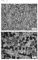
- FIG. 2 is photographs of a microstructure of a weld zone formed after welding using the wire rod corresponding to Inventive Example 7 and Comparative Example 1, and it is confirmed that in Comparative Example 1 (bottom), an austenite phase and a martensite phase were formed in a mixture, but in Inventive Example 7 (top), an austenite single phase structure was formed. Black dot shapes illustrated in FIG. 2 are oxides produced during welding.
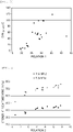
- FIG. 3 is a graph showing a relationship between [Relation 1] suggested in the present disclosure and the cryogenic impact toughness of the weld zone.
- FIG. 4 is a graph of a relationship between [Relation 2] suggested in the present disclosure and the strength at room temperature of the weld zone.
Landscapes
- Chemical & Material Sciences (AREA)
- Engineering & Computer Science (AREA)
- Mechanical Engineering (AREA)
- Organic Chemistry (AREA)
- Materials Engineering (AREA)
- Metallurgy (AREA)
- Thermal Sciences (AREA)
- Crystallography & Structural Chemistry (AREA)
- Physics & Mathematics (AREA)
- Manufacturing & Machinery (AREA)
- Arc Welding In General (AREA)
- Heat Treatment Of Steel (AREA)
- Nonmetallic Welding Materials (AREA)
Abstract
Description
- The present disclosure relates to a wire rod appropriate for a material for welding rods, and particularly, to a wire rod for welding rods having excellent strength at room temperature and excellent rod drawing properties and a method for manufacturing the same.
- Usually, welding rods mainly use a wire rod as a material thereof, and the wire rod is manufactured by hot rolling and then rod drawing at room temperature. Here, the wire rod is drawn to a specific diameter and is produced as a material for submerged arc welding, shielded metal arc welding, gas metal arc welding, gas tungsten arc welding, and the like and applied.
- A weld zone which is formed by performing welding of a base material by the welding method using the wire rod for welding rods is required to have high impact toughness, strength at room temperature, and the like, for the reason such as stability of a structure.
- As an example, it is necessary for materials for a cryogenic (base material) use to satisfy a strength at room temperature of 400 MPa and a tensile strength of 660 MPa, while satisfying a guaranteed impact toughness value of a weld zone at the time of welding of about 27 J at -196°C. These are standard values of a material which is currently widely used, and when the standard values are satisfied, materials at a higher temperature such as -100°C or -80°C may be applied.
- As a conventional material for welding materials, a wire rod including 50 wt% or more of nickel (Ni) with a total of more than 30 wt% of chromium (Cr) and molybdenum (Mo) for improving strength has been applied. As a representative example, provided are inconel and hastelloy materials.
- These materials are currently widely used in a cryogenic environment, but since inconel and hastelloy are expensive products to which expensive alloy elements such as Ni, Cr, and Mo are applied in large amounts, an increase in construction costs in the industrial field may result.
- Thus, development of a material for welding materials satisfying the physical property values of a base material weld zone, has excellent rod drawing properties at room temperature, and is economically favorable is demanded.
-
- (Patent Document 1)
Korean Patent Laid-Open Publication No. 10-2015-0039225 - (Patent Document 2)
Korean Patent Laid-Open Publication No. 10-2013-0052523 - An aspect of the present disclosure is to provide a material for welding materials, in particular, a wire rod appropriate for a material for welding rods, which has excellent rod drawing properties, high tensile strength at room temperature of a weld zone after welding, and excellent cryogenic impact toughness.
- An object of the present disclosure is not limited to the above description. The object of the present disclosure will be understood from the entire content of the present specification, and a person skilled in the art to which the present disclosure pertains will understand an additional object of the present disclosure without difficulty.
- According to an aspect of the present disclosure, a wire rod for welding rods includes, by weight: 0.05 to 0.8% of carbon (C), 18 to 31% of manganese (Mn), 0.05 to 0.7% of silicon (Si), 0.15% or less of nitrogen (N), 0.02% or less of phosphorus (P), and 0.01% or less of sulfur (S), with a balance of Fe and unavoidable impurities, wherein the following
Relation 1 is satisfied:

wherein each element refers to a content by weight of the element. - According to another aspect of the present disclosure, a method for manufacturing a wire rod for welding rods includes: preparing a steel workpiece or an ingot satisfying the alloy composition described above and
Relation 1; heat treating the steel workpiece or the ingot in a temperature range of 800 to 1250°C to manufacture a billet; and subjecting the billet to wire rod rolling in a temperature range of 800 to 1250°C to manufacture a wire rod. - As set forth above, according to an exemplary embodiment in the present disclosure, a wire rod having the physical properties required as a material for welding rods may be provided at low cost.
- In particular, the present disclosure may provide a wire rod which has excellent strength at room temperature and excellent cryogenic impact toughness of a weld zone after welding and has excellent rod drawing properties of a tensile strength of 850 MPa or less at room temperature and an elongation of 30% or more, though the use of expensive elements which have been mainly used for manufacturing a conventional wire rod for welding rods are greatly decreased. Thus, the wire rod of the present disclosure may be favorably applied as a wire rod for welding rods.
-
-
FIG. 1 illustrates a Schaeffler diagram (source: published in 1948(A.L. Schaeffler, Iron Age 162, 72 (1948)). -
FIG. 2 is photographs of a microstructure in a weld zone of the comparative examples and the inventive examples according to an exemplary embodiment in the present disclosure. -
FIG. 3 shows a relationship between [Relation 1] and cryogenic impact toughness of a weld zone, according to an exemplary embodiment in the present disclosure, as a graph. -
FIG. 4 shows a relationship between [Relation 2] and toughness at room temperature of a weld zone, according to an exemplary embodiment in the present disclosure, as a graph. - The present inventors confirmed a limitation of conventional materials used as a welding rod, and intensively studied in order to develop a material which allows the physical property values required for a weld zone to be secured at low cost and has excellent rod drawing properties.
- As a result, it was confirmed that low cost elements were used instead of high cost elements which have been used for manufacturing a conventional material for welding rods, thereby providing a wire rod which may form a weld zone having equivalent or better physical properties as compared with a conventional material while greatly lowering manufacturing costs, and thus, the present disclosure has been completed.
- In particular, since the wire rod for welding rods is manufactured by rod drawing at room temperature of a wire rod obtained by hot rolling, it requires to have excellent processability at room temperature, and for this, the present disclosure has a technical significance in optimizing a component system by properly using elements stable at room temperature.
- Specifically, it was confirmed that processability at room temperature depends on austenite stability of an alloy element and a processing type at the time of rod drawing, and the present disclosure is characterized in that carbon (C), nickel (Ni), manganese (Mn), nitrogen (N), and the like as appropriate elements therefor are controlled to appropriate contents, while a content relationship among them is suggested.
- Hereinafter, the present disclosure will be described in detail.
- The wire rod for welding rods according to an aspect of the present disclosure may include, by weight: 0.05 to 0.8% of carbon (C), 18 to 31% of manganese (Mn), 0.05 to 0.7% of silicon (Si), 0.15% or less of nitrogen (N), 0.02% or less of phosphorus (P), and 0.01% or less of sulfur (S).
- Hereinafter, the reason that the alloy composition of the wire rod for welding rods provided in the present disclosure is limited as described above will be described in detail.
- Meanwhile, unless otherwise particularly stated in the present disclosure, the content of each element is by weight and the ratio of the structure is by area.
- Carbon (C): 0.05 to 0.8%
- Carbon (C) is an austenite forming element, and is favorable for improving impact toughness of a weld zone in a cryogenic environment and improving strength at room temperature.
- When the content of C is less than 0.05%, it is difficult to secure the targeted strength at room temperature, but when the content is more than 0.8%, occurrences of cracks at high temperature, welding fumes, and spatter are promoted during welding.
- Therefore, C may be included at 0.05 to 0.8%, and more favorably at 0.78% or less.
- Manganese (Mn): 18 to 31%
- Manganese (Mn) is an element forming austenite, which is similar to C, and is an element favorable for improving impact toughness at cryogenic temperature.
- When the content of Mn is less than 18%, impact toughness is deteriorated by stress organic transformation at cryogenic temperature, but when the content is more than 31%, strength is lowered and a large amount of fumes is caused.
- Therefore, Mn may be included at 18 to 31%.
- Silicon (Si): 0.05 to 0.7%
- Silicon (Si) is an element added for improving flowability of welding materials at the time of welding, and is favorable to a deoxidation effect. In order to sufficiently obtain the effect described above, Si may be included at 0.05% or more. However, when the content is more than 0.7%, an eutectic compound is excessively precipitated and crack resistance is deteriorated.
- Therefore, Si may be included at 0.05 to 0.7%.
- Nitrogen (N): 0.15% or less
- Nitrogen (N) is an austenite forming element which is similar to C, and is effective in improving impact toughness of a weld zone in a cryogenic environment and improve strength at room temperature. Thus, in the present disclosure, N may be further added in terms of further promoting the effect of strength improvement by C.
- When the content of N is more than 0.15%, occurrences of cracks at a high temperature and pores are promoted during welding, and thus, considering the fact, N may be included at 0.15% or less. However, 0% may be fine.
- Phosphorus (P) : 0.02% or less and sulfur (S) : 0.01% or less
- Phosphorus (P) and sulfur (S) easily produce a low-melting point compound by addition in a small amount to lower the melting point of a material, thereby increasing cracking susceptibility at a high temperature. Thus, it is preferred that the contents of P and S are greatly decreased as much as possible.
- P and S may be inevitably added during the manufacturing process, and when each content is 0.02% or less and 0.01% or less, the physical properties of the wire rod are not influenced, and thus, each content may be limited as such.
- The wire rod of the present disclosure may further include elements favorable for forming the structure and securing the physical properties, in addition to the alloy composition described above.
- Specifically, the wire rod of the present disclosure may further include one or more of nickel (Ni), chromium (Cr), molybdenum (Mo), and vanadium (V), as described later. However, even in the case in which these elements are not included, it will not be difficult to form the structure and secure the physical properties in the present disclosure.
- Nickel (Ni): 8% or less
- Nickel (Ni) is an austenite forming element, and may be added for forming the structure of the wire rod completely into an austenite structure to secure cryogenic toughness.
- When the content of Ni is more than 8%, strength at room temperature is lowered, which is thus not preferred. Therefore, Ni may be included at 8% or less.
- Meanwhile, in the present disclosure, in the case in which the structure of the wire rod is completely formed into austenite by sufficiently including C, Mn, N, and the like described above, Ni may not be included.
- Chromium (Cr): 3.5% or less
- Chromium (Cr) is a ferrite forming element, and promotes production of ferrite to serve to expand an austenite area (
FIG. 1 ) . Thus, the higher content of Cr is favorable for improving strength at room temperature, but when Cr is added more than a specific content, Cr tends to be bonded to C to produce a carbide to cause cryogenic impact toughness to be lowered. - Thus, when Cr is added, Cr may be included up to 3.5% for improving strength at room temperature and austenite stability.
- Molybdenum (Mo): 3.5% or less
- Molybdenum (Mo) has a better effect of improving strength at room temperature than Cr, and has a lower bonding strength to C than Cr, and thus, when added, the cryogenic impact toughness is less lowered than Cr. However, Mo is an expensive element, and when added at a specific amount or more, manufacturing costs are greatly increased, and deterioration of cryogenic impact toughness may be caused.
- Therefore, when Mo is added, considering the manufacturing costs and strength improvement, Mo may be included up to 3.5%.
- Vanadium (V): 3.5% or less
- Vanadium (V) has a better effect of improving strength at room temperature than Cr and Mo. However, since the price of V is 10 times or more higher than the price of Cr and 4 times or more higher than the price of Mo, and thus, V has a limitation in obtaining a low cost material.
- Thus, when V is added, considering the manufacturing costs, V may be included up to 0.3%.
- The remaining component of the present disclosure is iron (Fe) . However, since in the common manufacturing process, unintended impurities may be inevitably incorporated from raw materials or the surrounding environment, the component may not be excluded. Since these impurities are known to those skilled in the common manufacturing process, the entire contents thereof are not particularly mentioned in the present specification.
- It is preferred that the wire rod of the present disclosure having the alloy composition described above satisfies the following component relation within the content range.
- First, in the present disclosure, the relationship among the elements favorable to austenite formation is suggested as the following [Relation 1], and the value of 24 or more is preferred.
- Second, in the present disclosure, while the austenite structure is illustrated, the relationship among the elements which may have strength at or above a targeted level is suggested as the following [Relation 2], and the value of 0 or more is preferred.


wherein each element refers to a content by weight of the element. - In general, the austenite stability of a steel is calculated by a Schaeffler diagram, as values of a Ni equivalent and a Cr equivalent. The equations for the Ni equivalent and the Cr equivalent are known as [Ni + 0.5Mn + 30(C+N)] and [Cr + 2.5Si + 1.8Mo].
- However, since the wire rod of the present disclosure is completely different from the conventional material including large amounts of Ni, Cr, and the like and is formed of a novel component composition, the relationship among the alloy elements was intended to be redefined.
- Thus, the present disclosure defines [Relation 1] and [Relation 2] described above and provides a wire rod satisfying the same, thereby providing a wire rod for welding rods which has a somewhat low tensile strength at room temperature in the state of a wire rod to have excellent rod drawing properties, has a target level or more of tensile strength at room temperature after welding, and may form a weld zone having physical properties required in a cryogenic environment.
- In particular, the structure of a wire rod manufactured by satisfying the value of [Relation 1] in the alloy component system suggested in the present disclosure may be formed into stable austenite, whereby a strength of 850 MPa or less and an elongation of 30% or more are illustrated, and thus, rod drawing properties are excellent and austenite may be stably secured even in a weld zone after welding. That is, in the present disclosure, a wire rod in which both the structure of the wire rod and the structure of the weld joint after welding using the wire rod have the austenite structure may be provided.
- The present disclosure may obtain an effect of securing a cryogenic (-197°C) impact toughness of a weld zone formed at the time of welding of 27 J or more, therefrom.
- Furthermore, the present disclosure satisfies [Relation 2] within the limited contents in using Ni, Cr, Mo, and V for sufficiently improving the strength at room temperature of the wire rod, thereby securing strength at room temperature while structurally maintaining an austenite phase after welding.
- That is to say, the present disclosure satisfies the alloy component system and
Relations - Moreover, the wire rod of the present disclosure has an austenite structure at room temperature to show a tensile strength of 850 MPa or less and an elongation of 30% or more, which correspond to the mechanical properties allowing rod drawing processing for being manufactured into a welding rod, and thus, the wire rod is favorable to processing at room temperature.
- Hereinafter, a method for manufacturing a wire rod for welding rods according to another aspect of the present disclosure will be described in detail.
- First, a steel workpiece or an ingot satisfying the alloy composition and the component relation (
Relations 1 and 2) described above is prepared, and then is heat treated in a temperature range of 800 to 1250°C, thereby manufacturing a billet. - When the temperature is lower than 800°C in the heat treatment, hot deformation resistance is increased to cause a decrease in productivity, but when the temperature is higher than 1250°C, crystal grains may become coarsened to reduce toughness.
- The heat-treated billet may be subjected to wire rod rolling to obtain a wire rod.
- Here, the wire rod rolling is carried out as hot rolling and may be carried out in a temperature range of 800 to 1250°C. When the temperature is lower than 800°C in the hot rolling, a load is increased during the rolling and deformation resistance may be increased, but when the temperature is higher than 1250°C, crystal grains may be excessively coarsened to reduce toughness.
- As described above, hot rolling and then cooling to room temperature are performed, thereby obtaining a wire rod having targeted microstructure and mechanical properties.
- Here, since the cooling may depend on the conditions applied in the manufacturing process of a common wire rod, it is not particularly limited in the present disclosure, and those skilled in the art may easily carry out it. However, as an example, the cooling may be performed as water cooling, at a cooling rate of 5°C/s or more.
- A final wire rod manufactured by the alloy composition and the manufacturing conditions suggested in the present disclosure has an austenite phase having high stability as a microstructure, thereby having strength at room temperature and elongation to allow rod drawing, and thus, is favorable to rod drawing processing. Furthermore, the wire rod may have a characteristic of forming a weld zone having excellent cryogenic impact toughness and tensile properties at room temperature at the time of welding.
- Here, the welding is not specifically limited, but may be any one of submerged arc welding (SAW), shielded metal arc welding (SMAW), gas tungsten arc welding (GTAW), and gas metal arc welding (GMAW).
- Hereinafter, the present disclosure will be specifically described through the following Examples. However, it should be noted that the following Examples are only for describing the present disclosure in detail by illustration, and are not intended to limit the right scope of the present disclosure. The reason is that the right scope of the present disclosure is determined by the matters described in the claims and reasonably inferred therefrom.
- An ingot having the alloy composition illustrated in the following Table 1 was prepared, and then heated at 1250°C to manufacture a billet. Immediately after the heating, the billet was hot rolled to a diameter of 5.5mm at 800 to 1250°C, and then water cooled at a cooling rate of 5°C/s or more to manufacture a wire rod having a diameter of 5.5mm.
- In order to confirm the tensile properties of the wire rod manufactured as described above, a tensile specimen was manufactured according to the standard of JIS No. 5, yield strength (TS) and tensile strength (TS) were measured at a rate of 40 mm/min at room temperature (about 25 to 30°C) with a tensile testing machine (Zwick/Roell), and the results are illustrated in Table 2.
- In addition, a microstructure for the same specimen as the tensile specimen was measured, and the type of phase was confirmed by measurement with an image analyzer (Olympus).
- Thereafter, each wire rod was subjected to rod drawing to a diameter of 4 mm. At this time, a process of heat treatment at 800 to 1250°C was performed, and if necessary, the rod drawing was performed under a reducing atmosphere environment containing hydrogen.
- While the wire rod which has been subjected to rod drawing was used as a welding rod, a high-manganese steel (a material to be welded, 0.4% of C - 24% of Mn - 0.3% of Si - a balance of Fe and unavoidable impurities, % by weight) was subjected to submerged arc welding at a heat input of 3.0 kJ/mm and the physical properties of deposited metal (weld metal) were evaluated.
- As the strength properties of the deposited metal, a tensile specimen was collected in a rod shape along the center in a direction of a welding line, and then yield strength (YS) and tensile strength (TS) were measured at room temperature (about 25 to 30°C) at a rate of 40 mm/min with a tensile testing machine (Zwick/Roell).
- In addition, a microstructure for the same specimen as the tensile specimen was measured, and the type of phase was confirmed by measurement with an image analyzer (Olympus).
- Then, the impact properties of the deposited metal were measured by collecting a standard specimen (KS B0809V notch specimen) in the center of the deposited metal perpendicular to the welding line, and then using a Charpy impact tester at -196°C.
- Each measurement result is illustrated in the following Table 2.
[Table 1] Classificat ion Alloy composition (wt%) [Relation] C Mn Si N P S Ni Cr Mo V 1 2 Comparative Example 1 0.26 15.10 0.14 0 0.0127 0.0050 0.34 1.29 0.52 0 19.54 4.01 Comparative Example 2 0.25 15.20 0.15 0 0.0120 0.0051 0.33 2.07 0 0 19.48 4.03 Comparative Example 3 0.25 15.90 0.14 0 0.0110 0.0047 1.22 0.48 0 0 21.60 1.43 Comparative Example 4 0.26 14.90 0.12 0 0.0128 0.0044 1.06 1.38 0.47 0 20.50 3.95 Comparative Example 5 0.25 16.30 0.16 0 0.0118 0.0048 1. 98 0.62 0 0 23.22 1.48 Comparative Example 6 0.10 15.75 0.56 0 0.0070 0.0110 3.70 1.21 0.03 0 23.17 0.71 Comparative Example 7 0.25 15.70 0.20 0 0.0118 0.0064 1.99 0.59 0 0 22.63 1.50 Comparative Example 8 0.09 16.37 0.37 0 0.0040 0.0140 2.99 1.28 0.04 0 22.50 0.78 Comparative Example 9 0.20 20.90 0.21 0 0.0120 0.0080 3.98 0 0 0 30.27 -0.73 Comparative Example 10 0.20 21.10 0.22 0 0.0110 0.0090 3.01 0 0 0 28.92 -0.59 Comparative Example 11 0.09 21.46 0.29 0 0.0030 0.0130 3.31 0.57 0.03 0 28.10 -0.86 Comparative Example 12 0.01 32.32 0.26 0 0.0120 0.0100 0 0 0 0 32.47 -3.13 Inventive Example 1 0.56 20.82 0.05 0 0 0 0 0 0 0 29.22 3.52 Inventive Example 2 0.13 18.93 0.66 0 0.0090 0.0090 2.85 0.98 0.65 0 25.44 1.72 Inventive Example 3 0.19 21.70 0.43 0 0.0100 0.0060 3.17 1.30 0.53 0 29.62 2.23 Inventive Example 4 0.78 18.72 0.50 0 0.0145 0.0021 7.68 1.63 0.01 0 42.71 7.16 Inventive Example 5 0.19 20.20 0.47 0 0.0090 0.0045 3.23 1.07 0.54 0 28.22 2.05 Inventive Example 6 0.36 21.50 0.45 0 0.0170 0.0040 0.02 2.95 0.64 0 26.93 7.15 Inventive Example 7 0.05 22.22 0.29 0 0.0089 0.0060 2.09 2.06 1.01 0.22 26.31 3.38 Inventive Example 8 0.37 22.06 0.29 0 0.0025 0.0070 2.07 3.05 1.00 0 30.92 7.74 Inventive Example 9 0.10 23.75 0.30 0 0.0025 0.0080 2.08 2.06 1.02 0 28.58 3.42 Inventive Example 10 0.15 24.77 0.29 0.05 0.0082 0.0090 2.04 1. 98 1.02 0.20 31.03 4.51 Inventive Example 11 0.15 24.00 0.29 0.10 0.0085 0.0090 2.05 3.01 1.00 0 31.03 6.30 Inventive Example 12 0.25 24.22 0.30 0 0.0024 0.0090 2.06 3.06 1.02 0.16 31.27 6.62 Inventive Example 13 0.31 30.93 0.34 0 0.0170 0.0060 0 0 3.01 0 35.58 6.03 Inventive Example 14 0.22 19.90 0.20 0 0.0110 0.0090 2.89 1.40 0.70 0 27.82 3.25 [Table 2] Classifi cation Wire rod and weld zone microstruct ure Wire rod Weld zone Yield strength (MPa) Tensile strength (MPa) Impact toughness (J) Yield strength (MPa) Tensile strength (MPa) Comparative Example 1 α'+γ 172 611 5 183 579 Comparative Example 2 α'+γ 168 468 8 183 452 Comparative Example 3 α'+γ 192 630 8 196 579 Comparative Example 4 α'+γ 191 635 9 206 579 Comparative Example 5 α'+γ 233 670 13 257 625 Comparative Example 6 α'+γ 359 646 16 395 613 Comparative Example 7 α'+γ 242 713 17 260 651 Comparative Example 8 α'+γ 365 566 24 384 566 Comparative Example 9 γ 330 673 44 352 653 Comparative Example 10 γ 339 687 39 366 648 Comparative Example 11 γ 357 642 53 372 607 Comparative Example 12 γ 325 541 57 331 517 Inventive Example 1 γ 409 697 38 420 682 Inventive Example 2 γ 389 720 60 412 680 Inventive Example 3 γ 403 743 52 432 702 Inventive Example 4 γ 404 766 30 433 742 Inventive Example 5 γ 404 718 57 423 702 Inventive Example 6 γ 428 784 57 437 715 Inventive Example 7 γ 432 722 90 432 713 Inventive Example 8 γ 434 827 98 463 762 Inventive Example 9 γ 414 785 98 425 715 Inventive Example 10 γ 437 771 97 452 715 Inventive Example 11 γ 404 798 97 442 732 Inventive Example 12 γ 435 753 97 449 745 Inventive Example 13 γ 407 764 118 435 715 Inventive Example 14 γ 427 689 53 432 683 - (In Table 2, α' refers to alpha prime martensite and γ refers to an austenite phase.)
- As illustrated in Tables 1 and 2, in Inventive Examples 1 to 14 satisfying [Relation 1] and [Relation 2] in the alloy component system suggested in the present disclosure, it was confirmed that not only the wire rod but also the weld zone structure after welding were all formed as an austenite single phase structure, and a strength favorable to rod drawing (a tensile strength of 850 MPa or less) was illustrated. In addition, though not described, the wire rod of the present disclosure (Inventive Examples 1 to 14) all had an elongation of 30% or more.
- Besides, when the wire rod was drawn and then was used as a welding rod to perform welding, it was confirmed that a weld zone having excellent cryogenic impact toughness and excellent strength at room temperature may be obtained.
- However, Inventive Example 4 having a relatively low Mn content but a high C content as compared with other inventive examples exhibited a somewhat low impact toughness of a weld zone of 30 J, but was confirmed to exceed the required physical properties. This is predicted to be due to the fact that when the content of manganese (Mn) in the wire rod is low due to the characteristic of carbon (C) of being solid solubilized in manganese (Mn), carbon is not entirely solid solubilized and is partly present as a carbide.
- However, in Comparative Examples 1 to 8 in which the content of manganese (Mn) was less than 18% and the value of [Relation 1] was less than 24, it was confirmed that a martensite phase was structurally partly formed though the value of [Relation 2] was 0 or more. Thus, a weld zone having the cryogenic impact toughness at the time of welding of less than 27 J and the strength at room temperature not satisfying the target was formed. This exhibited the results in which in the tensile test at room temperature, the martensite structure was first broken to deteriorate strength.
- Meanwhile, in Comparative Examples 9 to 12 including 18% or more of manganese (Mn), an austenite single phase structure was structurally formed, thereby obtaining a weld zone having a cryogenic impact toughness of 27 J or more. However, these all exhibited the value of [Relation 2] suggested in the present disclosure of less than 0, which means that the strength at room temperature in the weld zone was inferior.
-
FIG. 2 is photographs of a microstructure of a weld zone formed after welding using the wire rod corresponding to Inventive Example 7 and Comparative Example 1, and it is confirmed that in Comparative Example 1 (bottom), an austenite phase and a martensite phase were formed in a mixture, but in Inventive Example 7 (top), an austenite single phase structure was formed. Black dot shapes illustrated inFIG. 2 are oxides produced during welding. -
FIG. 3 is a graph showing a relationship between [Relation 1] suggested in the present disclosure and the cryogenic impact toughness of the weld zone. - As illustrated in
FIG. 3 , it was found that in the alloy component system limited in the present disclosure, only when the value of [Relation 1] is 25 or more, a weld zone having the cryogenic impact toughness at -196°C of 27 J or more may be obtained. -
FIG. 4 is a graph of a relationship between [Relation 2] suggested in the present disclosure and the strength at room temperature of the weld zone. - As illustrated in
FIG. 4 , it was found that in the alloy component system limited in the present disclosure, only when the value of [Relation 2] is 0 or more, a weld zone having a yield strength of 400 MPa or more and a tensile strength of 660 MPa or more may be obtained. - This shows that in order to appropriately apply the alloy component system limited in the present disclosure, that is, the wire rod including specific amounts of carbon, manganese, and the like as a welding rod, [Relation 1], and furthermore [Relation 2] according to the present disclosure should be satisfied.
- Also, high-priced elements which have been mainly used for manufacturing a conventional wire rod for welding rods are greatly reduced, thereby providing the wire rod having the required physical properties as the material for welding rods at low costs.
Claims (9)
- A wire rod for welding rods comprising, by weight: 0.05 to 0.8% of carbon (C), 18 to 31% of manganese (Mn), 0.05 to 0.7% of silicon (Si), 0.15% or less of nitrogen (N), 0.02% or less of phosphorus (P), and 0.01% or less of sulfur (S), with a balance of Fe and unavoidable impurities,
wherein the following Relation 1 is satisfied:
- The wire rod for welding rods of claim 1, further comprising: one or more selected from the group consisting of 8% or less of nickel (Ni), 3.5% or less of chromium (Cr), 3.5% or less of molybdenum (Mo), and 0.3% or less of vanadium (V), wherein the following Relation 2 is satisfied:

- The wire rod for welding rods of claim 1, wherein the wire rod includes an austenite single phase structure as a microstructure.
- The wire rod for welding rods of claim 1, wherein the wire rod has a tensile strength at room temperature of 850 MPa or less.
- The wire rod for welding rods of claim 1, wherein when welding is performed using the wire rod, a weld zone having a yield strength at room temperature of 400 MPa or more and a tensile strength at room temperature of 660 MPa or more is formed.
- The wire rod for welding rods of claim 1, wherein when welding is performed using the wire rod, a weld zone having a Charpy impact toughness at -196°C of 27 J or more is formed.
- The wire rod for welding rods of claim 5 or 6, wherein the welding is any one of submerged arc welding (SAW), shielded metal arc welding (SMAW), gas tungsten arc welding (GTAW), and gas metal arc welding (GMAW).
- A method for manufacturing a wire rod for welding rods, the method comprising:
preparing a steel workpiece or an ingot which includes, by weight: 0.05 to 0.8% of carbon (C), 18 to 31% of manganese (Mn), 0.05 to 0.7% of silicon (Si), 0.15% or less of nitrogen (N), 0.02% or less of phosphorus (P), and 0.01% or less of sulfur (S), with a balance of Fe and unavoidable impurities and satisfies the following Relation 1:heat treating the steel workpiece or the ingot in a temperature range of 800 to 1250°C to manufacture a billet, andsubjecting the billet to wire rod rolling in a temperature range of 800 to 1250°C to manufacture a wire rod: wherein each element refers to a content by weight of the element.
 - The method for manufacturing a wire rod for welding rods of claim 8, wherein the steel workpiece or the ingot further includes one or more selected from the group consisting of 8% or less of nickel (Ni), 3.5% or less of chromium (Cr), 3.5% or less of molybdenum (Mo), and 0.3% or less of vanadium (V), and satisfies the following Relation 2:

Applications Claiming Priority (2)
| Application Number | Priority Date | Filing Date | Title |
|---|---|---|---|
| KR1020190128586A KR102321317B1 (en) | 2019-10-16 | 2019-10-16 | Wire rod for welding rod nd method for manufacturing thereof |
| PCT/KR2020/013581 WO2021075777A1 (en) | 2019-10-16 | 2020-10-06 | Wire rod for welding rods and method for manufacturing same |
Publications (2)
| Publication Number | Publication Date |
|---|---|
| EP4046743A1 true EP4046743A1 (en) | 2022-08-24 |
| EP4046743A4 EP4046743A4 (en) | 2023-04-19 |
Family
ID=75537894
Family Applications (1)
| Application Number | Title | Priority Date | Filing Date |
|---|---|---|---|
| EP20877049.5A Pending EP4046743A4 (en) | 2019-10-16 | 2020-10-06 | WIRE ROD FOR WELDING RODS AND METHOD OF MAKING IT |
Country Status (7)
| Country | Link |
|---|---|
| US (1) | US12447563B2 (en) |
| EP (1) | EP4046743A4 (en) |
| JP (1) | JP7478821B2 (en) |
| KR (1) | KR102321317B1 (en) |
| CN (1) | CN114555283A (en) |
| CA (1) | CA3152469A1 (en) |
| WO (1) | WO2021075777A1 (en) |
Families Citing this family (1)
| Publication number | Priority date | Publication date | Assignee | Title |
|---|---|---|---|---|
| WO2023032932A1 (en) * | 2021-08-31 | 2023-03-09 | Jfeスチール株式会社 | Submerged arc welding method |
Family Cites Families (25)
| Publication number | Priority date | Publication date | Assignee | Title |
|---|---|---|---|---|
| US4256516A (en) | 1978-12-26 | 1981-03-17 | Nippon Kokan Kabushiki Kaisha | Method of manufacturing non-magnetic Fe-Mn steels having low thermal expansion coefficients and high yield points |
| JPS5659597A (en) | 1979-10-19 | 1981-05-23 | Daido Steel Co Ltd | Filler metal for high-manganese, nonmagnetic steel |
| JP3175551B2 (en) | 1995-09-19 | 2001-06-11 | 住友金属工業株式会社 | Manufacturing method of non-magnetic welded wire mesh |
| KR100238014B1 (en) | 1995-12-26 | 2000-01-15 | 이구택 | Manufacturing method of welding rod wire |
| JP2004195542A (en) | 2002-12-20 | 2004-07-15 | Jfe Steel Kk | Steel wire for gas shielded arc welding |
| KR100910494B1 (en) | 2007-12-26 | 2009-07-31 | 주식회사 포스코 | Manufacturing method of welding rod wire |
| KR101060785B1 (en) * | 2008-12-03 | 2011-08-30 | 주식회사 포스코 | Wire rod for 600MPa special welding rod which can omit heat treatment and its manufacturing method |
| EP2656964A4 (en) | 2010-12-22 | 2016-05-25 | Kobe Steel Ltd | Welding solid wire and welding metal |
| CN102649202B (en) * | 2011-02-23 | 2015-06-17 | 宝山钢铁股份有限公司 | Stainless steel welding wire |
| KR101304657B1 (en) | 2011-06-30 | 2013-09-05 | 주식회사 포스코 | Weld metal joint having excellent low temperature toughness |
| JP5469648B2 (en) | 2011-11-10 | 2014-04-16 | 株式会社神戸製鋼所 | Welding materials for cryogenic steel |
| CA2890476C (en) | 2012-11-22 | 2017-03-21 | Posco | Welded joint of extremely low-temperature steel, and welding materials for preparing same |
| KR20150066372A (en) * | 2013-12-06 | 2015-06-16 | 주식회사 포스코 | Material for submerged arc welding and gas metal arc welding having excellent impact resistance and abrasion resistance properties |
| CN105813799B (en) * | 2013-12-06 | 2019-06-07 | Posco公司 | High-strength welded joint with excellent low temperature impact toughness and flux-cored wire for arc welding therefor |
| KR101536471B1 (en) | 2013-12-24 | 2015-07-13 | 주식회사 포스코 | Ultra-high strength steel sheet for welding structure with superior haz toughness for high heat input welding and method for manufacturing the same |
| CN104607819B (en) | 2014-11-27 | 2017-10-31 | 宝山钢铁股份有限公司 | A kind of gas protecting welding wire and its manufacture method |
| KR101657825B1 (en) * | 2014-12-24 | 2016-09-20 | 주식회사 포스코 | Tungsten inert gas welding material for high manganese steel |
| EP3037205B1 (en) | 2014-12-25 | 2018-06-27 | Kabushiki Kaisha Kobe Seiko Sho (Kobe Steel, Ltd.) | Wire for gas shield arc welding |
| KR101568642B1 (en) | 2015-09-07 | 2015-11-12 | 주식회사 포스코 | Material for submerged arc welding and gas metal arc welding having excellent impact resistance and abrasion resistance properties |
| CA3022940C (en) * | 2016-05-02 | 2024-06-04 | Exxonmobil Research And Engineering Company | Field dissimilar metal welding technology for enhanced wear resistant high manganese steel |
| WO2017192619A1 (en) * | 2016-05-02 | 2017-11-09 | Exxonmobil Research And Engineering Company | Field girth welding technology for high manganese steel slurry pipelines |
| KR101879068B1 (en) | 2016-12-13 | 2018-07-16 | 주식회사 포스코 | High strength wire rod having excellent impact toughness and method for manufacturing the same |
| KR20180074860A (en) | 2016-12-23 | 2018-07-04 | 주식회사 포스코 | Welded joint with excellent ultra-low temperature toughness and strength |
| KR20190050926A (en) | 2017-12-26 | 2019-05-14 | 주식회사 포스코 | Method for manufacturing slurry pipe using high manganese steel |
| KR20210143296A (en) | 2019-03-29 | 2021-11-26 | 제이에프이 스틸 가부시키가이샤 | filler metal for TIG welding |
-
2019
- 2019-10-16 KR KR1020190128586A patent/KR102321317B1/en active Active
-
2020
- 2020-10-06 CA CA3152469A patent/CA3152469A1/en active Pending
- 2020-10-06 US US17/765,777 patent/US12447563B2/en active Active
- 2020-10-06 EP EP20877049.5A patent/EP4046743A4/en active Pending
- 2020-10-06 JP JP2022522588A patent/JP7478821B2/en active Active
- 2020-10-06 WO PCT/KR2020/013581 patent/WO2021075777A1/en not_active Ceased
- 2020-10-06 CN CN202080071743.1A patent/CN114555283A/en active Pending
Also Published As
| Publication number | Publication date |
|---|---|
| CA3152469A1 (en) | 2021-04-22 |
| KR20210045165A (en) | 2021-04-26 |
| CN114555283A (en) | 2022-05-27 |
| US12447563B2 (en) | 2025-10-21 |
| JP2022552353A (en) | 2022-12-15 |
| US20220371131A1 (en) | 2022-11-24 |
| JP7478821B2 (en) | 2024-05-07 |
| WO2021075777A1 (en) | 2021-04-22 |
| KR102321317B1 (en) | 2021-11-02 |
| EP4046743A4 (en) | 2023-04-19 |
Similar Documents
| Publication | Publication Date | Title |
|---|---|---|
| EP2980231B1 (en) | Method for manufacturing pearlite rail | |
| JP5157606B2 (en) | TIG welding method of high strength steel using flux cored wire | |
| EP2180074B1 (en) | High-strength low-alloy steel excellent in the resistance to high-pressure hydrogen environment embrittlement and process for manufacturing the steel | |
| US11505841B2 (en) | High-strength steel product and method of manufacturing the same | |
| JP5942916B2 (en) | Thick-walled steel plate with excellent low-temperature toughness at the center of plate thickness after PWHT and method for producing the same | |
| EP2573200A1 (en) | Automotive underbody part having excellent low cycle fatigue properties, and process for production thereof | |
| KR102237487B1 (en) | Wire rod for welding rod and method for manufacturing thereof | |
| EP3392362B1 (en) | Wear resistant steel material excellent in toughness and internal quality, and method for manufacturing same | |
| JP2006225718A (en) | DEPOSITED METAL FOR HIGH STRENGTH Cr-Mo STEEL HAVING EXCELLENT LOW TEMPERATURE TOUGHNESS AND SR CRACK RESISTANCE | |
| EP4541502A1 (en) | Low-nickel high-manganese austenite wear-resistant steel welding wire rod and welding wire | |
| CN113840933B (en) | Thick steel plate and method for producing same | |
| KR101674768B1 (en) | Manufacturing method of continuous casting roll with excellent high temperature anti-abrasion | |
| US12447563B2 (en) | Wire rod for welding rods and method for manufacturing same | |
| KR102112172B1 (en) | Cold-rolled steel sheet for flux cored wire and manufacturing the same | |
| KR102134310B1 (en) | Cold-rolled steel sheet for flux cored wire and manufacturing the same | |
| KR101911898B1 (en) | WELDED JOINT OF HIGH Mn STEEL WITH EXCELLENT HOT CRACKING RESISTANCE | |
| EP3699314A1 (en) | Utility ferritic stainless steel having excellent hot workability, and manufacturing method therefor | |
| RU2380452C2 (en) | Steel with increased welding capabilities for submarines hull | |
| JP5458923B2 (en) | Welded joint with excellent brittle fracture resistance | |
| CN114850627A (en) | Flux-cored wire, weld metal, gas-shielded arc welding method, and method for manufacturing welded joint | |
| JP2024005022A (en) | thick steel plate | |
| JP2022065798A (en) | Seamless steel pipe | |
| EP4454800A1 (en) | Welded steel pipe for slurry transporting and manufacturing method for same | |
| KR101443445B1 (en) | Non-heated type high strength hot-rolled steel sheet and method of manufacturing the same | |
| JP4267521B2 (en) | High-strength liquid phase diffusion bonding joint with excellent weld toughness, high-strength steel for liquid phase diffusion bonding, and liquid phase diffusion bonding method |
Legal Events
| Date | Code | Title | Description |
|---|---|---|---|
| STAA | Information on the status of an ep patent application or granted ep patent |
Free format text: STATUS: THE INTERNATIONAL PUBLICATION HAS BEEN MADE |
|
| PUAI | Public reference made under article 153(3) epc to a published international application that has entered the european phase |
Free format text: ORIGINAL CODE: 0009012 |
|
| STAA | Information on the status of an ep patent application or granted ep patent |
Free format text: STATUS: REQUEST FOR EXAMINATION WAS MADE |
|
| 17P | Request for examination filed |
Effective date: 20220506 |
|
| AK | Designated contracting states |
Kind code of ref document: A1 Designated state(s): AL AT BE BG CH CY CZ DE DK EE ES FI FR GB GR HR HU IE IS IT LI LT LU LV MC MK MT NL NO PL PT RO RS SE SI SK SM TR |
|
| DAV | Request for validation of the european patent (deleted) | ||
| DAX | Request for extension of the european patent (deleted) | ||
| A4 | Supplementary search report drawn up and despatched |
Effective date: 20230316 |
|
| RIC1 | Information provided on ipc code assigned before grant |
Ipc: C21D 9/00 20060101ALI20230310BHEP Ipc: C21D 6/00 20060101ALI20230310BHEP Ipc: C21D 8/06 20060101ALI20230310BHEP Ipc: C22C 38/00 20060101ALI20230310BHEP Ipc: C22C 38/22 20060101ALI20230310BHEP Ipc: C22C 38/12 20060101ALI20230310BHEP Ipc: C22C 38/46 20060101ALI20230310BHEP Ipc: C22C 38/38 20060101ALI20230310BHEP Ipc: C22C 38/44 20060101ALI20230310BHEP Ipc: C22C 38/58 20060101ALI20230310BHEP Ipc: C22C 38/02 20060101ALI20230310BHEP Ipc: C22C 38/04 20060101ALI20230310BHEP Ipc: B23K 35/40 20060101ALI20230310BHEP Ipc: B23K 35/02 20060101ALI20230310BHEP Ipc: B23K 35/30 20060101AFI20230310BHEP |