EP4046690A1 - Second stage regulator for emergency breathing systems - Google Patents
Second stage regulator for emergency breathing systems Download PDFInfo
- Publication number
- EP4046690A1 EP4046690A1 EP22157322.3A EP22157322A EP4046690A1 EP 4046690 A1 EP4046690 A1 EP 4046690A1 EP 22157322 A EP22157322 A EP 22157322A EP 4046690 A1 EP4046690 A1 EP 4046690A1
- Authority
- EP
- European Patent Office
- Prior art keywords
- stage regulator
- nosepiece
- housing
- coupled
- regulator
- Prior art date
- Legal status (The legal status is an assumption and is not a legal conclusion. Google has not performed a legal analysis and makes no representation as to the accuracy of the status listed.)
- Pending
Links
Images


Classifications
-
- A—HUMAN NECESSITIES
- A62—LIFE-SAVING; FIRE-FIGHTING
- A62B—DEVICES, APPARATUS OR METHODS FOR LIFE-SAVING
- A62B7/00—Respiratory apparatus
- A62B7/14—Respiratory apparatus for high-altitude aircraft
-
- A—HUMAN NECESSITIES
- A62—LIFE-SAVING; FIRE-FIGHTING
- A62B—DEVICES, APPARATUS OR METHODS FOR LIFE-SAVING
- A62B9/00—Component parts for respiratory or breathing apparatus
- A62B9/02—Valves
- A62B9/022—Breathing demand regulators
-
- A—HUMAN NECESSITIES
- A62—LIFE-SAVING; FIRE-FIGHTING
- A62B—DEVICES, APPARATUS OR METHODS FOR LIFE-SAVING
- A62B9/00—Component parts for respiratory or breathing apparatus
- A62B9/02—Valves
- A62B9/022—Breathing demand regulators
- A62B9/025—Breathing demand regulators with tilting opening action
-
- A—HUMAN NECESSITIES
- A62—LIFE-SAVING; FIRE-FIGHTING
- A62B—DEVICES, APPARATUS OR METHODS FOR LIFE-SAVING
- A62B9/00—Component parts for respiratory or breathing apparatus
- A62B9/04—Couplings; Supporting frames
-
- A—HUMAN NECESSITIES
- A62—LIFE-SAVING; FIRE-FIGHTING
- A62B—DEVICES, APPARATUS OR METHODS FOR LIFE-SAVING
- A62B9/00—Component parts for respiratory or breathing apparatus
- A62B9/06—Mouthpieces; Nose-clips
-
- B—PERFORMING OPERATIONS; TRANSPORTING
- B63—SHIPS OR OTHER WATERBORNE VESSELS; RELATED EQUIPMENT
- B63C—LAUNCHING, HAULING-OUT, OR DRY-DOCKING OF VESSELS; LIFE-SAVING IN WATER; EQUIPMENT FOR DWELLING OR WORKING UNDER WATER; MEANS FOR SALVAGING OR SEARCHING FOR UNDERWATER OBJECTS
- B63C11/00—Equipment for dwelling or working underwater; Means for searching for underwater objects
- B63C11/02—Divers' equipment
- B63C11/18—Air supply
- B63C11/186—Mouthpieces
-
- B—PERFORMING OPERATIONS; TRANSPORTING
- B63—SHIPS OR OTHER WATERBORNE VESSELS; RELATED EQUIPMENT
- B63C—LAUNCHING, HAULING-OUT, OR DRY-DOCKING OF VESSELS; LIFE-SAVING IN WATER; EQUIPMENT FOR DWELLING OR WORKING UNDER WATER; MEANS FOR SALVAGING OR SEARCHING FOR UNDERWATER OBJECTS
- B63C11/00—Equipment for dwelling or working underwater; Means for searching for underwater objects
- B63C11/02—Divers' equipment
- B63C11/18—Air supply
- B63C11/22—Air supply carried by diver
- B63C11/2227—Second-stage regulators
Definitions
- the present invention is generally related to breathing systems and more specifically emergency breathing systems.
- a second stage regulator includes a housing, a first nosepiece coupled to a first lever, a second nosepiece coupled to a second lever, a first spring located in the housing and coupled to the first nosepiece and the first lever, a second spring located in the housing and coupled to the second nosepiece and the second lever, a mouthpiece, and a coupler coupled to the housing, wherein the first spring and the second spring bias the first nosepiece and the second nosepiece towards each other.
- the first nosepiece and the second nosepiece may include a removable nose pad.
- the coupler may include a threaded coupler.
- the coupler may include a swivel coupler.
- the coupler may be coupled to a hose.
- the coupler may be coupled to an air tank and a user may inhale a breathing mix stored in the air tank via a pathway formed the housing and the mouthpiece.
- the housing may further include at least one exhaust port allowing exhaled air to leave the second stage regulator.
- the housing may further include a check valve preventing exhaled air from entering a pathway allowing a user to inhale a breathing mix.
- the pathway may include a poppet chamber having a poppet.
- the exhaust port may be located in an exhaust cover coupled to the housing.
- the first nosepiece and the first lever may rotate about a circumference of the housing when an actuation force is applied to the first lever.
- the first nosepiece and the first lever may be formed in a unitary component.
- the housing may include a front cover coupled to the housing.
- the front cover may engage with a portion of the first nosepiece, the first lever, the second nosepiece, and the second lever to maintain the first nosepiece, the first lever, the second nosepiece, and the second lever in engagement with the housing.
- the first spring may be located in a first spring seat formed in the housing and the second spring is located in a second spring seat in the housing.
- an emergency breathing system including an air tank and a second stage regulator coupled to the air tank, the second stage regulator including a housing, a first nosepiece coupled to a first lever, a second nosepiece coupled to a second lever, a first spring located in the housing and coupled to the first nosepiece and the first lever, and a second spring located in the housing and coupled to the second nosepiece and the second lever, where the first spring and the second spring bias the first nosepiece and the second nosepiece towards each other.
- the emergency breathing system may further include a first stage regulator coupled to the air tank, wherein the second stage regulator is coupled to the first stage regulator.
- the emergency breathing system may further include a hose coupled to the first stage regulator, wherein the hose is coupled to the second stage regulator.
- the air tank may be formed from a material selected from the group consisting of aluminum and a composite.
- the air tank may store a breathing mix and has a working pressure of approximately 3000 PSI to 4500 PSI.
- the air tank may include a first threaded coupler, the first stage regulator includes a second threaded coupler, the hose includes a first swivel coupler, and the second stage regulator includes a second swivel coupler, the air tank is coupled to the first stage regulator by the first threaded coupler and the second threaded coupler, and the hose is coupled to the second stage regulator via the first swivel coupler and the second swivel coupler.
- EBS Emergency Breathing Systems
- a re-breather or compressed air unit allow for users to breath while underwater.
- EBS are particularly useful in aircraft applications, allowing aircraft occupants to breathe underwater in the event of a crash into a body of water. This allows the occupants additional time to escape the aircraft, and the deployment of EBS can significantly reduce the number of deaths in survivable crashes in bodies of water.
- Emergency breathing systems in accordance with the invention can include a second stage regulator with integrated nosepieces.
- the nosepieces hold the user's nose closed to facilitate the use of the EBS while underwater.
- the nosepieces can be integrated into the body of the second stage regulator to improve reliability and ensure easy, single-handed operability in the event of a crash.
- the second stage regulator can include one or more integrated exhaust covers.
- the integrated exhaust covers reduce the effort required to exhale while using the EBS. This reduced breathing effort can aid in usability and survivability when the user is breathing hard, such as due to stress during an underwater crash.
- Second stage regulators can include integrated exhaust covers and/or nosepieces located on the left and right sides of the regulator body.
- the integrated exhaust covers can be formed into the body of the second stage regulator and/or in a back plate of the second stage regulator.
- the integrated exhaust covers can include one or more exhaust vents allowing exhaled air to be released from the second stage regulator when a user exhales.
- the integrated exhaust covers further protect any internal mechanisms, such as exhaust values, from becoming entangled or clogged by debris.
- the nosepieces can engage with and cover the body of the second stage regulator.
- the nosepieces extend from a front end of the regulator body to a rear end of the regulator body.
- the nosepieces extend from a rear end of a front cover ring attached to the front of the regulator body to a front end of a back plate attached to the rear of the regulator body.
- the nosepieces are located on the left and right sides of the second stage regulator and generally extend from the top side of the regulator body to the lower end of the exhaust vents.
- Each of the nosepieces can have a nose clip located at the top end of the nosepiece and a lever located at the lower end of the nosepiece.
- the levers of the nosepieces are located on the lower left and right sides of the body near a coupler located at the bottom of the second stage regulator, allowing for one-handed operation of the nosepieces.
- the nosepieces can have a generally solid body that protects the internal components of the second stage regulator.
- the nosepieces cover any internal springs or spring housings that engage with the nosepieces as described in more detail herein.
- the nosepieces form a housing cover for the regulator body, protecting the internal mechanisms and springs from the external environment. For example, particularly in underwater environments, a variety of debris can interfere with the operation of the nosepieces, such as by becoming entangled with springs that hold the nosepieces in a closed position. By covering these internal elements, the performance and reliability of the second stage regulator is improved.
- the nosepieces include an exhaust opening, formed near the levers, which allow air to flow freely from the integrated exhaust covers while the second stage regulator is in use.
- FIGS. 1A-B are line drawings of exemplary second stage regulators for emergency breathing systems.
- FIG 1A shows a second stage regulator 100 with a threaded coupler 112.
- the threaded coupler 112 has screw threads that can be used to join the second stage regulator to an air tank, hose, or any other device.
- the threaded coupler 112 can have straight threads, taper threads, and/or any other configuration of threads as appropriate to a particular application of the invention.
- the threaded coupler 112 can be formed from steel, brass, PTFE, PVC, nylon, bronze, iron, and/or any other material as appropriate.
- Second stage regulator 100 further includes integrated exhaust covers 116 and nosepieces 114.
- the nosepieces 114 include levers located near the threaded coupler 112, allowing for one-handed operation of second stage regulator 100.
- Nosepieces 114 form a housing cover for the body of the second stage regulator 100.
- Nosepieces 114 have an opening formed near the levers and positioned relative to the exhaust covers 116, allowing for the free flow of exhaled air during operation of the second stage regulator 100.
- FIG. 1B shows a second stage regulator 150 with a swivel fitting 162.
- swivel fitting 162 allow for a hose (or anything coupled to the swivel fitting) to swivel with respect to the fitting.
- swivel fitting 162 includes a perforated hollow bolt and cylindrical union allowing for fluid transfer from a hose or air tank through the second stage regulator 150.
- Second stage regulator 150 further includes integrated exhaust covers 166 and nosepieces 164.
- the nosepieces 164 include levers located near the swivel coupler 162, allowing for one-handed operation of second stage regulator 150.
- Nosepieces 164 form a housing cover for the body of the second stage regulator 150.
- Nosepieces 164 have an opening formed near the levers and positioned relative to the exhaust covers 166, allowing for the free flow of exhaled air during operation of the second stage regulator 150.
- second stage regulators are shown and described with respect to FIGS. 1A-B , any of a variety of other second stage regulators, including those that use couplers other than those illustrated, can be used in accordance with the invention.
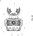
- FIGS. 2A-C are perspective drawings of exemplary second stage regulators.
- FIG. 2A shows a front view of a second stage regulator 200
- FIG. 2B shows a rear view of the second stage regulator 200
- FIG. 2C shows an underside view of the second stage regulator 200.
- Second stage regulator 200 includes a housing 210 having nosepieces 212 and levers 214 coupled to the housing 210.
- Levers 214 when depressed, rotate about the circumference of the housing 210 and cause nosepieces 212 to open so that a user can insert their nose between the nosepieces 212.
- Mouthpiece 218 can be placed in the user's mouth, thereby allowing the user to inhale a breathing mix via opening 220.
- a spring returns the levers 214 to their original position, thereby causing nosepieces 212 to close.
- Second stage regulator 200 further includes a coupler 216, such as a threaded coupler and/or a swivel fitting as described herein. Exhaust vents 222 allow exhaled air to be released from the second stage regulator 200 when a user exhales.
- a lever 214 and its corresponding nosepiece 212 are a unitary component. In several examples, a lever 214 and its corresponding nosepiece 212 are coupled via a linkage or other coupling element.
- the exhaust vents 222 can be formed into the housing 210 and/or formed into a separate component that couples with the housing 210.
- the mouthpiece 218 can be formed into the housing 210 and/or be separate component that couples with the housing 210
- any of a variety of other components can be included in a second stage regulator in accordance with the invention.
- FIG. 3A-C are line drawings illustrating cross-sections of exemplary second stage regulators.
- FIG. 3A shows a cross-section of a second stage regulator 300 with the front of the second stage regulator on the left hand side of the drawing and the mouthpiece on the right hand side of the drawing, the top of the nosepiece on the top of the drawing, and a coupler on the bottom of the drawing.
- FIG. 3B shows a second cross-section of the second stage regulator 300 with the left hand side of the second stage regulator on the left hand side of the drawing and the right hand side of the second stage regulator 300 on the right hand side of the drawing.
- Second stage regulator 300 includes a housing 301, a nose clip 340, exhaust vents 305, a back plate 306, a mouthpiece 342, a purge cover 308, a lever 333, a diaphragm assembly 310, a front cover 311, exhaust valves 312, an inlet chamber 314, a valve housing 315, a coupler 316 having threads 317, a poppet chamber 323 levers 321, and/or one or more springs 330.
- a user When in use, a user actuates levers 321 to rotate nosepieces 340 into an open position. With the nosepieces 340 in an open position, the user can place the mouthpiece 342 in their mouth and release the levers 321.
- the springs 330 coupled to the nosepieces 340 and/or levers 321, push the nosepieces 340 and/or levers 321 into the closed position, clamping the user's nose closed with the nosepieces 340.
- the springs 330 are contained within spring housings formed on the housing 301.
- the nosepieces 340 and levers 321 can rotate about the circumference of the housing 301.
- the front cover 311 engages with a tab or groove on the nosepieces 340 and/or levers 321 to hold the nosepieces 340 and/or levers 321 in engagement with the housing 301.
- a nosepiece and its corresponding lever can be formed as a unitary piece and/or be separate pieces coupled (e.g. via one or more linkages) as appropriate to the requirements of specific applications of the invention.
- the second stage regulator 300 includes a unitary left nosepiece and lever coupled to the left hand side of the second stage regulator 300 and a unitary right nosepiece and lever coupled to the right hand side of the second stage regulator 300.
- the coupler 316 is removably engaged with the housing 301.
- the orifice seat 328 is adjustably engaged with the coupler 316 and sealed with O-ring 326.
- a valve housing 315 is installed in the inlet chamber 314.
- the valve housing 315 can have a poppet chamber 323 having a poppet spring 329, a poppet 332, a poppet seat 324, and an adjustment tube 331.
- the poppet seat 324 engages with orifice seat 328 in order to control the flow of air through a pathway formed by coupler 316, the poppet chamber 323, inlet chamber 314, and mouthpiece 342.
- the poppet spring 329 biases the poppet 332 into a closed position.
- the rate e.g.
- the spring 329 can be determined based on the target pressure for a breathing mix to be inhaled via the second stage regulator 300.
- the rate of the spring 329 can be adjusted with the adjustment tube 331.
- the lever 333 engages the valve housing 315 and the poppet 332, such that movement of the lever 333 moves the poppet 332. In this way, the spring 329 is compressed when a gas mix is being inhaled through the pathway, thereby moving the poppet 332 up to disengage with the orifice seat 328 and allowing the flow of air.
- the poppet spring 329 forces the poppet 332 back into the closed position, preventing the flow of air.
- the poppet 332 moves up allowing air flow in the poppet chamber 323 , exhaust valves 312 are closed, and air can flow through the pathway to be inhaled by the user.
- One or more exhaust vents 305 can be formed in a back cover 306.
- the back plate 306 can be coupled to the housing 301. Any fastener and/or direct connection between the back plate and the 306 can be used in accordance with the requirements of specific applications of examples of the invention.
- the pressure of the exhaled gas moves the diaphragm assembly 310 allowing the lever 333 to move the poppet 332 to the closed position, preventing the exhaled gas from flowing through poppet chamber 323.
- airflow in the poppet chamber 323 is closed, exhaust valves 312 are opened, and the exhaled gas can pass through a pathway formed by the mouthpiece 342, the inlet chamber 314, and the exhaust vents 305 to exit the second stage regulator 300.
- the purge cover 308 can be located within front cover 311 and accessed via an opening in the front cover 311. The purge cover 308 can be actuated to flush these contaminants from the second stage regulator 300.
- the purge cover 308 engages with diaphragm assembly 310, which engages with lever 333. When actuating the purge cover 308, the lever 333 is depressed, moving the poppet 332 up, thereby allowing the pressurized breathing mix to flow through the poppet chamber 323 and allowing any air and/or contaminants to be ejected from the interior of the second stage regulator 300.
- purging the second stage regulator 300 requires the user to exhale while the purge cover 308 is depressed.
- depressing the purge cover 308 causes air flow in the poppet chamber 323, causing pressurized breathing mix to enter the balancing chamber 314 and flow out of the front cover 311 of the second stage regulator 300.
- second stage regulators can include a variety of couplers. These couplers can be removably attached to the second stage regulator.
- FIG. 3C shows a cross-section of a second stage regulator 350 having a swivel coupler 367.
- the swivel coupler 367 includes a swivel coupling 365, swivel retainer 368, O-ring 364, O-ring 369, and swivel housing 366.
- the swivel housing 366 can be rotated relative to the second stage regulator 350, thereby allowing objects coupled to the swivel coupling 365, such as a hose or an air tank, to rotate with respect to the second stage regulator 350.
- second stage regulators Although a variety of second stage regulators are shown and described with respect to FIGS. 3A-C , any of a variety of other second stage regulators can be used in accordance with examples of the invention.
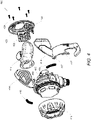
- FIG. 4 is an illustration of the components of an exemplary second stage regulator.
- Second stage regulator 400 includes a regulator body 410 that accepts a front cover 412.
- Regulator body 410 includes spring housings 415 that accept springs 416.
- Springs 416 further couple to posts, grooves, and/or slots in the nosepiece components 414 such that, when nosepiece components 414 are coupled to the regulator body 410, the nosepiece components 414 can be moved between an open position and a closed position by the springs 416. In the open position, a user's nose can be located between the nose pads of nosepiece components 414, while in the closed position the tension created by the springs 416 cause the nose pads coupled to nosepiece components 414 to hold the user's nose closed.
- the regulator body further includes a coupler capable of accepting a mouthpiece 418, which allows the user to breathe through the second stage regulator.
- the regulator body 410 is also shaped to accept a rear cover 420 having integrated exhaust vents 422.
- the rear cover 420 can fit over the mouthpiece 418 secure the mouthpiece 418 to the regulator body 410.
- the rear cover 420 can be secured to the regulator body 410 via screws 424, although any attachment elements, such as clips, pins, threads, and the like can be used as appropriate.
- the nosepiece components 414 can be coupled to the regulator body via the front cover 412 and/or rear cover 420.
- the front cover 412 and/or rear cover 420 when coupled to the regulator body 410, define one or more grooves in which one or more portions (e.g. tabs 417) of the nosepiece components 414 engage and allow the nosepiece components 414 to move around the regulator body 410.
- the regulator body 410 defines the grooves in which the nosepiece components 414 can move and those where the nosepiece components 414 define a groove which accepts a tab extending from the regulator body 410, front cover 412 and/or rear cover 420, can be used as appropriate to the requirements of specific applications of examples of the invention.
- second stage regulators Although a variety of components of second stage regulators are shown and described with respect to FIG. 4 , any of a variety of other second stage regulators can be used in accordance with examples of the invention.
- FIG. 5A-C are illustrations of the components of a second stage regulator in accordance with examples of the invention.
- FIG. 5A shows the components of a first construction of a second stage regulator 500.
- the second stage regulator 500 includes a regulator body 501, exhaust valves 502, a back plate 503, a diaphragm 504, a purge cover 505, front cover ring 506, a left nose clip 507, a right nose clip 508, screws 509, O-ring 510, valve housing 511, O-ring 512, adjustment tube 525, lever 513, poppet spring 514, coupler 515, poppet 516, poppet seat 517, washer 518, nose clip springs 519, orifice seat 520, O-ring 521, and mouthpiece 522.
- Second stage regulator 500 is assembled as follows.
- the front portion of regulator body 501 includes threads allowing front cover ring 506 to be screwed onto regulator body 501.
- Diaphragm 510 is placed in regulator body 501.
- Purge cover 505 is placed on top of diaphragm 510 and front cover ring 506 is screwed onto regulator body 501.
- Mouthpiece 522 can be placed on an opening on the rear side of the regulator body 501.
- Exhaust valves 502 can be coupled to exhaust ports on the left and right hand sides of the regulator body 501.
- Back plate 503 can be placed over the rear of regulator body 501, covering the exhaust valves 502 and securing the mouthpiece 522 to the regulator body 501.
- Back plate 503 can be secured to the regulator body 501 using any of a variety of fasteners or clips, such as screws 509. Nose clip springs 519 can be places in spring housings located on the left and right hand sides of the regulator body 501.
- Left nose clip 507 can be coupled to the left hand side of the regulator body 501 and right nose clip 508 can be coupled to the right hand side of the regulator body 501.
- the left nose clip 507 and the right nose clip 508 can couple directly to the regulator body 501 and/or be secured to the regulator body 501 by front cover ring 506 and/or back plate 503.
- valve housing 511 can be installed (e.g. by screwing, press fit, or any other attachment) and sealed using O-ring 510.
- Orifice seat 520 and O-ring 521 can be assembled in coupler 515.
- a poppet assembly can be inserted into valve housing 511.
- the poppet assembly includes adjustment tube 525, a poppet spring 514, a poppet 516 placed within poppet spring 514, a washer 518 placed on the top end of poppet 516, a poppet seat 517 placed on the lower end of poppet 516, and lever 513 inserted in valve housing 511 holding the poppet 516.
- Coupler 515 can be screwed, press fit, or otherwise coupled to valve housing 511 and sealed using O-ring 512.
- the coupler 515 can have a variety of attachment components, such as threads, to attach hoses or any other external devices to the second stage regulator 500.
- the spring 514 can engage with the adjustment tube 525 and adjusting adjustment tube 525 can modify the rate, compression, and/or force of spring 514.
- FIG. 5B shows the components of a second construction of a second stage regulator 530.
- Second stage regulator 530 includes housing 531, exhaust valve 532, back plate 533, diaphragm 534, purge cover 535, front cover ring 536, left nose clip 537, right nose clip 538, screws 539, O-ring 540, valve housing 541, O-ring 542, lever 543, poppet spring 544, coupler 545, poppet 546, poppet seat 547, washer 548, nose clip springs 549, orifice seat 550, O-ring 551, mouthpiece 552, and adjustment tube 553.
- Second stage regulator 530 is assembled as follows.
- the front portion of regulator body 531 includes threads allowing front cover ring 536 to be screwed onto regulator body 531.
- Diaphragm 534 is placed in housing 531.
- Purge cover 535 is placed on top of diaphragm 534 and front cover ring 536 is screwed onto regulator body 531.
- Mouthpiece 552 can be placed on an opening on the rear side of the regulator body 531.
- Exhaust valves 532 can be coupled to exhaust ports on the left and right hand sides of the regulator body 531.
- Back plate 533 can be placed over the rear of regulator body 531, covering the exhaust valves 532 and securing the mouthpiece 552 to the regulator body 531.
- Back plate 533 can be secured to the regulator body 531 using any of a variety of fasteners or clips, such as screws 539.
- Nose clip springs 549 can be places in spring housings located on the left and right hand sides of the regulator body 531.
- Left nose clip 537 can be coupled to the left hand side of the regulator body 531 and right nose clip 538 can be coupled to the right hand side of the regulator body 538.
- the left nose clip 537 and the right nose clip 538 can couple directly to the regulator body 531 and/or be secured to the regulator body 531 by front cover ring 536 and/or back plate 533.
- valve housing 541 can be installed (e.g. by screwing, press fit, or any other attachment) and sealed using O-ring 540.
- Orifice seat 550 and O-ring 551 can be assembled in swivel coupler 545.
- a poppet assembly can be inserted into valve housing 541.
- the poppet assembly includes an adjustment tube 553, a poppet spring 544 engaging with the adjustment tube 553, a poppet 546 placed within poppet spring 544, a washer 548 placed between the poppet 546 and the poppet spring 544, a poppet seat 547 placed on the lower end of poppet 546, a lever 543 inserted in valve housing 541 holding poppet 546, and swivel coupler 545 screwed (or otherwise coupled) to the valve housing 541 and sealed using O-ring 542.
- Orifice seat 550 is threaded within swivel coupler 545 and sealed by O-ring 551.
- the poppet spring 544 can be adjusting the adjustment tube 553 as described herein.
- the swivel coupler 545 includes a swivel coupling 551, swivel retainer 556, O-ring 553, O-ring 555.
- the swivel coupling 551 can be rotated relative to the second stage regulator 350, thereby allowing objects coupled to the swivel coupling 551, such as a hose or an air tank, to rotate with respect to the second stage regulator 530.
- FIG. 5C shows the components of a second construction of a second stage regulator 570.
- the second stage regulator 570 includes a regulator body 571, exhaust valves 572, a back plate 573, a diaphragm 574, a purge cover 575, front cover ring 576, a housing cover 590, screws 577, O-ring 578, valve housing 579, O-ring 580, adjustment tube 589, lever 581, poppet spring 582, coupler 583, poppet 584, poppet seat 585, washer 586, orifice seat 587, washer 588, and mouthpiece 589.
- Second stage regulator 570 is assembled as follows.
- the front portion of regulator body 571 includes threads allowing front cover ring 576 to be screwed onto regulator body 571.
- Diaphragm 574 is placed in regulator body 571.
- Purge cover 575 is placed on top of diaphragm 574 and front cover ring 576 is screwed onto regulator body 576.
- Mouthpiece 589 can be placed on an opening on the rear side of the regulator body 571.
- Exhaust valves 572 can be coupled to exhaust ports on the left and right hand sides of the regulator body 571.
- Back plate 573 can be placed over the rear of regulator body 571, covering the exhaust valves 572 and securing the mouthpiece 589 to the regulator body 571.
- Back plate 573 can be secured to the regulator body 571 using any of a variety of fasteners or clips, such as screws 577.
- Housing cover 590 can be placed on top of regulator body 571, covering spring housings formed in the regulator body 571.
- the housing cover 590 can couple directly to the regulator body 571 and/or be secured to the regulator body 571 by front cover ring 576 and/or back plate 573.
- the housing cover 590 can be installed on the regulator body 571 in place of any nosepieces and/or levers.
- the housing cover 590 can include tabs and/or grooves with engage with corresponding grooves/tabs in the back plate 573, purge cover 575, and/or front cover ring 576 of the second stage regulator 570.
- the housing cover 590 can be used to protect particular elements of the second stage regulator 570 and/or added as a styling piece in accordance with the requirements of specific applications of the invention.
- valve housing 579 can be installed (e.g. by screwing, press fit, or any other attachment) and sealed using O-ring 578.
- a poppet assembly can be inserted into valve housing 579.
- the poppet assembly includes an adjustment tube 589, a poppet spring 582 placed around adjustment tube 589, a poppet 584 placed within poppet spring 582, a washer 586 placed on the top end of poppet 584, a poppet seat 585 placed on the lower end of poppet 584.
- the poppet assembly can be held within the valve housing 579 by lever 581.
- Coupler 583 can be screwed, press fit, or otherwise coupled to valve housing 579 and sealed using O-ring 580.
- Orifice seat 587 and O-ring 588 can be assembled in coupler 583. Adjusting adjustment tube 589 can modify the rate, compression, and/or force of spring 582 as described herein.
- second stage regulators are shown and described with respect to FIGS. 5A-C , any of a variety of other second stage regulators including those with more or fewer components or components arranged in a different matter, can be used in accordance with the invention.
- a variety of second stage regulators in accordance with the invention have nosepieces designed to hold a user's nose closed during operation, thereby improving the user's ability to breath a breathing mix via the second stage regulator.
- the nosepieces can include replaceable nose pads. In this way, new and/or clean nose pads can be inserted by a user prior to use.
- the nose pads are shaped to be press fit into holes in the nosepieces.
- the nose pads are shaped to be slid over the ends of the nosepieces. It should be noted that non-replaceable nosepieces, such as those nose pads over molded onto the nosepieces, can also be used.
- the mouthpiece of the second stage regulator can also be replaceable by the user.
- the nose pads and/or mouthpieces used in the second stage regulators can be formed out of any of a variety of materials or a combination of materials, such as silicone, rubber, foam, ethylene-vinyl acetate, vinyl, thermopolymers, and the like.
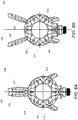
- FIGS. 6A-B are line drawings of nosepieces of an exemplary second stage regulator.
- FIG. 6A shows a second stage regulator 610 with nosepieces 612 in a closed position. In the closed position, the nosepieces 612 are held together via spring tension such that an object located between the nosepieces 612 is squeezed.
- Levers 614 are spaced away from a vertical centerline 602 of the second stage regulator 610. The levers 614 can be pushed toward the coupler located at the bottom of the second stage regulator 610 to rotate the nosepieces 612 around the second stage regulator 610 and away from each other into an open position.
- the levers 614 are placed below a horizontal centerline 604 of the second stage regulator 600. By placing the levers 614 below the horizontal centerline 604, the levers 614 can be easily accessed for one-handed operation.
- FIG. 6B shows a second stage regulator 660 with nosepieces 662 in an open position.
- levers 664 are located close to the coupler located at the bottom of the second stage regulator 660, which causes the nosepieces 662 be spaced apart from each other.
- the spring tension causes the levers 664 to rotate around the body of the second stage regulator 660 and the nosepieces 662 to move towards each other into the closed position.
- the levers 664 are located to the left and right sides of vertical centerline 652 and below horizontal centerline 654. The motion of the levers 664 can be constrained, respectively, to the lower left and lower right quadrants formed by the vertical centerline 652 and horizontal centerline 654.
- second stage regulators Although a variety of second stage regulators are shown and described with respect to FIGS. 6A-B , any of a variety of other second stage regulators can be used in accordance with the invention.
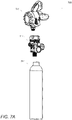
- FIGS. 7A-B are illustrations of exemplary emergency breathing systems.
- FIG. 7A shows the elements of an emergency breathing system, including second stage regulator 710, first stage regulator 712, and air tank 714.
- the second stage regulator 710 can be coupled to the first stage regulator 712, which in turn is coupled to the air tank 714. Any couplers are described herein can be used, and different couplers can be used on different elements.
- the air tank 714 stores air (e.g. a breathing mix) that can be used by a user to breath underwater.
- the breathing mix stored in the air tank 714 is typically stored at a working pressure, such as between approximately 3000 and 4500 PSI.
- the first stage regulator 712 can be used to control the flow of and regulate the pressure of the breathing mix coming from the air tank 714.
- the first stage regulator 712 can both turn on and off the flow of the breathing mix along with stepping down the air pressure to a level appropriate for a user to breathe while underwater, such as 140 PSI.
- the first stage regulator 712 is an unbalanced piston regulator and the second stage regulator 710 is a balanced regulator.
- one or more of the second stage regulator 710, first stage regulator 712, and air tank 714 have a pressure gauge indicating the pressure of the breathing mix stored in the air tank 714.
- the air tank 714 is constructed from steel, aluminum, composite, and/or any other material as appropriate to the requirements of specific applications of examples of the invention.
- FIG. 7B shows an exemplary emergency breathing system 750.
- the emergency breathing system 750 can be pre-assembled and/or assembled by a user in the event of a crash.
- the mouthpiece of the second stage regulator 760 can be placed in the mouth of the user while the user depresses the levers to open the nose clips.
- the user can release the levers to secure the nosepieces against the user's nose, thereby closing the user's nose.
- the user can then inhale through their mouth to breathe the breathing mix stored in the air tank 764.
- the user can exhale through their mouth to exhaust their breath through the exhaust ports of the second stage regulator 760.
- the user can also eject spit or other water via the purge valve of the second stage regulator 760.
- the second stage regulator 760 can be coupled to the first stage regulator 762 via a hose 766. This arrangement allows the air tank 764 and first stage regulator 762 assembly to be located securely on a person, such as on a life vest while the second stage regulator 760 is located in the user's mouth.
- the first stage regulator 762 can include a threaded coupler and screw directly onto the air tank 764.
- the hose 766 can include a coupler on each end, with a first end coupling to the first stage regulator 762 and the second end coupling to the second stage regulator 760.
- the second stage regulator 760 and the second end of the hose 766 each have a swivel coupler, thereby allowing the hose 766 to rotate with respect to the second stage regulator 760.
- the first stage regulator 762 and the first end of the hose 766 each have a swivel coupler, thereby allowing the hose 766 to rotate with respect to the first stage regulator 762.
- the second stage regulator 760 and the second end of the hose 766 each have a threaded coupler and the hose 766 is screwed onto the second stage regulator 760.
- the first stage regulator 762 and the first end of the hose 766 each have a threaded coupler and the hose 766 is screwed onto the first stage regulator 762. In this way, couplers can be mixed and matched across the various components of the emergency breathing system 750.
- a second stage regulator comprising a housing; a first nosepiece coupled to a first lever; a second nosepiece coupled to a second lever; a first spring located in the housing and coupled to the first nosepiece and the first lever; a second spring located in the housing and coupled to the second nosepiece and the second lever; a mouthpiece; and a coupler coupled to the housing; wherein the first spring and the second spring bias the first nosepiece and the second nosepiece towards each other.
- Clause 2 the second stage regulator of clause 1, wherein the first nosepiece and the second nosepiece comprise a removable nose pad.
- Clause 3 the second stage regulator of any of the clauses 1 - 2, wherein the coupler comprises a threaded coupler.
- Clause 4 the second stage regulator of any of the clauses 1 - 3, wherein the coupler comprises a swivel coupler.
- Clause 5 the second stage regulator of any of the clauses 1 - 4, wherein the coupler is coupled to a hose.
- Clause 6 the second stage regulator of any of the clauses 1 - 5, wherein the coupler is coupled to an air tank and a user can inhale a breathing mix stored in the air tank via a pathway formed the housing and the mouthpiece.
- Clause 7 the second stage regulator of any of the clauses 1 - 6, wherein the housing further comprises at least one exhaust port allowing exhaled air to leave the second stage regulator.
- Clause 8 the second stage regulator of clause 7, wherein the housing further comprises a check valve preventing exhaled air from entering a pathway allowing a user to inhale a breathing mix.
- Clause 9 the second stage regulator of clause 8, wherein the pathway comprises a poppet chamber having a poppet.
- Clause 10 the second stage regulator of clause 7, wherein the exhaust port is located in an exhaust cover coupled to the housing.
- Clause 11 the second stage regulator of any of the clauses 1 - 10, wherein the first nosepiece and the first lever rotate about a circumference of the housing when an actuation force is applied to the first lever.
- Clause 12 the second stage regulator of any of the clauses 1 - 11, wherein the first nosepiece and the first lever are formed in a unitary component.
- Clause 13 the second stage regulator of any of the clauses 1 - 12, wherein the housing comprises a front cover coupled to the housing, the front cover engages with a portion of the first nosepiece, the first lever, the second nosepiece, and the second lever to maintain the first nosepiece, the first lever, the second nosepiece, and the second lever in engagement with the housing.
- Clause 14 the second stage regulator of any of the clauses 1 - 13, wherein the first spring is located in a first spring seat formed in the housing and the second spring is located in a second spring seat in the housing.
- an emergency breathing system comprising: an air tank and a second stage regulator coupled to the air tank, the second stage regulator comprising a housing, a first nosepiece coupled to a first lever, a second nosepiece coupled to a second lever, a first spring located in the housing and coupled to the first nosepiece and the first lever, and a second spring located in the housing and coupled to the second nosepiece and the second lever, where the first spring and the second spring bias the first nosepiece and the second nosepiece towards each other.
- Clause 16 the emergency breathing system of clause 15, further comprising a first stage regulator coupled to the air tank, wherein the second stage regulator is coupled to the first stage regulator.
- Clause 17 the emergency breathing system of clause 16, further comprising a hose coupled to the first stage regulator, wherein the hose is coupled to the second stage regulator.
- Clause 18 the emergency breathing system of clause 17, wherein the air tank comprises a first threaded coupler, the first stage regulator comprises a second threaded coupler, the hose comprises a first swivel coupler, and the second stage regulator comprises a second swivel coupler; the air tank is coupled to the first stage regulator by the first threaded coupler and the second threaded coupler; and the hose is coupled to the second stage regulator via the first swivel coupler and the second swivel coupler.
- Clause 19 the emergency breathing system of any of the clauses 15 - 18, wherein the air tank is formed from a material selected from the group consisting of aluminum and a composite.
- Clause 20 the emergency breathing system of any of the clauses 15 - 19, wherein the air tank stores a breathing mix and has a working pressure of approximately 3000 PSI to 4500 PSI.
- Clause 21 an emergency breathing system comprising a second stage regulator according to any of the clauses 1 - 14 and an air tank coupled to the second stage regulator.
Abstract
Description
- This application claims priority to
U.S. Patent Application No. 17/665,268, entitled "Second Stage Regulator for Emergency Breathing Systems" and filed February 4, 2022 U.S. Provisional Patent Application No. 63/151,090, entitled "Second Stage Regulator for Emergency Breathing Systems" and filed February 19, 2021 - The present invention is generally related to breathing systems and more specifically emergency breathing systems.
- When an aircraft crashes into a body of water, it typically inverts and sinks. In survivable crashes, a large percentage of occupants of the aircraft often perish due to an inability to escape the aircraft while underwater.
- Systems and methods for emergency breathing systems in accordance with the invention are disclosed. According to a first aspect, there is provided a second stage regulator includes a housing, a first nosepiece coupled to a first lever, a second nosepiece coupled to a second lever, a first spring located in the housing and coupled to the first nosepiece and the first lever, a second spring located in the housing and coupled to the second nosepiece and the second lever, a mouthpiece, and a coupler coupled to the housing, wherein the first spring and the second spring bias the first nosepiece and the second nosepiece towards each other.
- The first nosepiece and the second nosepiece may include a removable nose pad.
- The coupler may include a threaded coupler.
- The coupler may include a swivel coupler.
- The coupler may be coupled to a hose.
- The coupler may be coupled to an air tank and a user may inhale a breathing mix stored in the air tank via a pathway formed the housing and the mouthpiece.
- The housing may further include at least one exhaust port allowing exhaled air to leave the second stage regulator.
- The housing may further include a check valve preventing exhaled air from entering a pathway allowing a user to inhale a breathing mix.
- The pathway may include a poppet chamber having a poppet.
- The exhaust port may be located in an exhaust cover coupled to the housing.
- The first nosepiece and the first lever may rotate about a circumference of the housing when an actuation force is applied to the first lever.
- The first nosepiece and the first lever may be formed in a unitary component.
- The housing may include a front cover coupled to the housing.
- The front cover may engage with a portion of the first nosepiece, the first lever, the second nosepiece, and the second lever to maintain the first nosepiece, the first lever, the second nosepiece, and the second lever in engagement with the housing.
- The first spring may be located in a first spring seat formed in the housing and the second spring is located in a second spring seat in the housing.
- According to a second aspect, there is provided an emergency breathing system including an air tank and a second stage regulator coupled to the air tank, the second stage regulator including a housing, a first nosepiece coupled to a first lever, a second nosepiece coupled to a second lever, a first spring located in the housing and coupled to the first nosepiece and the first lever, and a second spring located in the housing and coupled to the second nosepiece and the second lever, where the first spring and the second spring bias the first nosepiece and the second nosepiece towards each other.
- The emergency breathing system may further include a first stage regulator coupled to the air tank, wherein the second stage regulator is coupled to the first stage regulator.
- The emergency breathing system may further include a hose coupled to the first stage regulator, wherein the hose is coupled to the second stage regulator.
- The air tank may be formed from a material selected from the group consisting of aluminum and a composite.
- The air tank may store a breathing mix and has a working pressure of approximately 3000 PSI to 4500 PSI.
- The air tank may include a first threaded coupler, the first stage regulator includes a second threaded coupler, the hose includes a first swivel coupler, and the second stage regulator includes a second swivel coupler, the air tank is coupled to the first stage regulator by the first threaded coupler and the second threaded coupler, and the hose is coupled to the second stage regulator via the first swivel coupler and the second swivel coupler.
- The skilled person will appreciate that, except where mutually exclusive, a feature described in relation to any one of the above aspects may be applied mutatis mutandis to any other aspect. Furthermore, except where mutually exclusive, any feature described herein may be applied to any aspect and/or combined with any other feature described herein.
- Other objects, advantages and novel features, and further scope of applicability of the present invention will be set forth in part in the detailed description to follow, and in part will become apparent to those skilled in the art upon examination of the following, or may be learned by practice of the invention. The objects and advantages of the invention may be realized and attained by means of the instrumentalities and combinations particularly pointed out in the claims.
- The description will be more fully understood with reference to the following figures, which are presented as examples of the invention and should not be construed as a complete recitation of the scope of the invention, wherein:
-
FIGS. 1A-B are line drawings of second stage regulators for exemplary emergency breathing systems; -
FIGS. 2A-C are perspective drawings of exemplary second stage regulators; -
FIG. 3A-C are line drawings illustrating a cross section of exemplary second stage regulators; -
FIG. 4 is an illustration of the components of an exemplary second stage regulator; -
FIG. 5A-C are illustrations of the components of an exemplary second stage regulator; -
FIGS. 6A-B are line drawings of nosepieces of an exemplary second stage regulator in; and -
FIGS. 7A-B are illustrations of exemplary emergency breathing systems. - Turning now to the drawings, exemplary systems and methods for emergency breathing systems are disclosed. Emergency Breathing Systems (EBS), whether a re-breather or compressed air unit, allow for users to breath while underwater. EBS are particularly useful in aircraft applications, allowing aircraft occupants to breathe underwater in the event of a crash into a body of water. This allows the occupants additional time to escape the aircraft, and the deployment of EBS can significantly reduce the number of deaths in survivable crashes in bodies of water.
- Emergency breathing systems in accordance with the invention can include a second stage regulator with integrated nosepieces. The nosepieces hold the user's nose closed to facilitate the use of the EBS while underwater. The nosepieces can be integrated into the body of the second stage regulator to improve reliability and ensure easy, single-handed operability in the event of a crash. Additionally, the second stage regulator can include one or more integrated exhaust covers. The integrated exhaust covers reduce the effort required to exhale while using the EBS. This reduced breathing effort can aid in usability and survivability when the user is breathing hard, such as due to stress during an underwater crash.
- A variety of exemplary emergency breathing systems and second stage regulators are described in more detail below.
- Second stage regulators can include integrated exhaust covers and/or nosepieces located on the left and right sides of the regulator body. The integrated exhaust covers can be formed into the body of the second stage regulator and/or in a back plate of the second stage regulator. The integrated exhaust covers can include one or more exhaust vents allowing exhaled air to be released from the second stage regulator when a user exhales. The integrated exhaust covers further protect any internal mechanisms, such as exhaust values, from becoming entangled or clogged by debris.
- The nosepieces can engage with and cover the body of the second stage regulator. In a variety of examples, the nosepieces extend from a front end of the regulator body to a rear end of the regulator body. In several examples, the nosepieces extend from a rear end of a front cover ring attached to the front of the regulator body to a front end of a back plate attached to the rear of the regulator body. The nosepieces are located on the left and right sides of the second stage regulator and generally extend from the top side of the regulator body to the lower end of the exhaust vents. Each of the nosepieces can have a nose clip located at the top end of the nosepiece and a lever located at the lower end of the nosepiece. In particular, the levers of the nosepieces are located on the lower left and right sides of the body near a coupler located at the bottom of the second stage regulator, allowing for one-handed operation of the nosepieces. The nosepieces can have a generally solid body that protects the internal components of the second stage regulator. In particular, the nosepieces cover any internal springs or spring housings that engage with the nosepieces as described in more detail herein. In this way, the nosepieces form a housing cover for the regulator body, protecting the internal mechanisms and springs from the external environment. For example, particularly in underwater environments, a variety of debris can interfere with the operation of the nosepieces, such as by becoming entangled with springs that hold the nosepieces in a closed position. By covering these internal elements, the performance and reliability of the second stage regulator is improved. In many examples, the nosepieces include an exhaust opening, formed near the levers, which allow air to flow freely from the integrated exhaust covers while the second stage regulator is in use.
-
FIGS. 1A-B are line drawings of exemplary second stage regulators for emergency breathing systems.FIG 1A shows asecond stage regulator 100 with a threadedcoupler 112. In many examples, the threadedcoupler 112 has screw threads that can be used to join the second stage regulator to an air tank, hose, or any other device. The threadedcoupler 112 can have straight threads, taper threads, and/or any other configuration of threads as appropriate to a particular application of the invention. The threadedcoupler 112 can be formed from steel, brass, PTFE, PVC, nylon, bronze, iron, and/or any other material as appropriate.Second stage regulator 100 further includes integrated exhaust covers 116 andnosepieces 114. Thenosepieces 114 include levers located near the threadedcoupler 112, allowing for one-handed operation ofsecond stage regulator 100.Nosepieces 114 form a housing cover for the body of thesecond stage regulator 100.Nosepieces 114 have an opening formed near the levers and positioned relative to the exhaust covers 116, allowing for the free flow of exhaled air during operation of thesecond stage regulator 100. -
FIG. 1B shows asecond stage regulator 150 with aswivel fitting 162. In several examples, swivel fitting 162 allow for a hose (or anything coupled to the swivel fitting) to swivel with respect to the fitting. In many examples, swivel fitting 162 includes a perforated hollow bolt and cylindrical union allowing for fluid transfer from a hose or air tank through thesecond stage regulator 150.Second stage regulator 150 further includes integrated exhaust covers 166 andnosepieces 164. Thenosepieces 164 include levers located near theswivel coupler 162, allowing for one-handed operation ofsecond stage regulator 150.Nosepieces 164 form a housing cover for the body of thesecond stage regulator 150.Nosepieces 164 have an opening formed near the levers and positioned relative to the exhaust covers 166, allowing for the free flow of exhaled air during operation of thesecond stage regulator 150. - Although a variety of second stage regulators are shown and described with respect to
FIGS. 1A-B , any of a variety of other second stage regulators, including those that use couplers other than those illustrated, can be used in accordance with the invention. -
FIGS. 2A-C are perspective drawings of exemplary second stage regulators.FIG. 2A shows a front view of asecond stage regulator 200,FIG. 2B shows a rear view of thesecond stage regulator 200, andFIG. 2C shows an underside view of thesecond stage regulator 200. -
Second stage regulator 200 includes ahousing 210 havingnosepieces 212 andlevers 214 coupled to thehousing 210.Levers 214, when depressed, rotate about the circumference of thehousing 210 and causenosepieces 212 to open so that a user can insert their nose between thenosepieces 212.Mouthpiece 218 can be placed in the user's mouth, thereby allowing the user to inhale a breathing mix viaopening 220. When thelevers 214 are released, a spring returns thelevers 214 to their original position, thereby causingnosepieces 212 to close.Second stage regulator 200 further includes acoupler 216, such as a threaded coupler and/or a swivel fitting as described herein. Exhaust vents 222 allow exhaled air to be released from thesecond stage regulator 200 when a user exhales. - In a variety of examples, a
lever 214 and itscorresponding nosepiece 212 are a unitary component. In several examples, alever 214 and itscorresponding nosepiece 212 are coupled via a linkage or other coupling element. The exhaust vents 222 can be formed into thehousing 210 and/or formed into a separate component that couples with thehousing 210. Themouthpiece 218 can be formed into thehousing 210 and/or be separate component that couples with thehousing 210 - Although a variety of components for second stage regulators are shown and described with respect to
FIGS. 2A-C , any of a variety of other components can be included in a second stage regulator in accordance with the invention. -
FIG. 3A-C are line drawings illustrating cross-sections of exemplary second stage regulators.FIG. 3A shows a cross-section of asecond stage regulator 300 with the front of the second stage regulator on the left hand side of the drawing and the mouthpiece on the right hand side of the drawing, the top of the nosepiece on the top of the drawing, and a coupler on the bottom of the drawing.FIG. 3B shows a second cross-section of thesecond stage regulator 300 with the left hand side of the second stage regulator on the left hand side of the drawing and the right hand side of thesecond stage regulator 300 on the right hand side of the drawing.Second stage regulator 300 includes ahousing 301, anose clip 340, exhaust vents 305, aback plate 306, amouthpiece 342, apurge cover 308, alever 333, adiaphragm assembly 310, afront cover 311,exhaust valves 312, aninlet chamber 314, avalve housing 315, acoupler 316 havingthreads 317, apoppet chamber 323levers 321, and/or one or more springs 330. - When in use, a user actuates
levers 321 to rotatenosepieces 340 into an open position. With thenosepieces 340 in an open position, the user can place themouthpiece 342 in their mouth and release thelevers 321. Thesprings 330, coupled to thenosepieces 340 and/orlevers 321, push thenosepieces 340 and/orlevers 321 into the closed position, clamping the user's nose closed with thenosepieces 340. In many examples, thesprings 330 are contained within spring housings formed on thehousing 301. Thenosepieces 340 andlevers 321 can rotate about the circumference of thehousing 301. In a number of examples, thefront cover 311 engages with a tab or groove on thenosepieces 340 and/orlevers 321 to hold thenosepieces 340 and/orlevers 321 in engagement with thehousing 301. A nosepiece and its corresponding lever can be formed as a unitary piece and/or be separate pieces coupled (e.g. via one or more linkages) as appropriate to the requirements of specific applications of the invention. In many examples, thesecond stage regulator 300 includes a unitary left nosepiece and lever coupled to the left hand side of thesecond stage regulator 300 and a unitary right nosepiece and lever coupled to the right hand side of thesecond stage regulator 300. - In a variety of examples, the
coupler 316 is removably engaged with thehousing 301. Theorifice seat 328 is adjustably engaged with thecoupler 316 and sealed with O-ring 326. In many examples, avalve housing 315 is installed in theinlet chamber 314. Thevalve housing 315 can have apoppet chamber 323 having apoppet spring 329, apoppet 332, apoppet seat 324, and anadjustment tube 331. Thepoppet seat 324 engages withorifice seat 328 in order to control the flow of air through a pathway formed bycoupler 316, thepoppet chamber 323,inlet chamber 314, andmouthpiece 342. Thepoppet spring 329 biases thepoppet 332 into a closed position. The rate (e.g. force) of thespring 329 can be determined based on the target pressure for a breathing mix to be inhaled via thesecond stage regulator 300. The rate of thespring 329 can be adjusted with theadjustment tube 331. Thelever 333 engages thevalve housing 315 and thepoppet 332, such that movement of thelever 333 moves thepoppet 332. In this way, thespring 329 is compressed when a gas mix is being inhaled through the pathway, thereby moving thepoppet 332 up to disengage with theorifice seat 328 and allowing the flow of air. When not inhaling, thepoppet spring 329 forces thepoppet 332 back into the closed position, preventing the flow of air. When a pressurized gas is provided atcoupler 316 and/or when a user inhales, thepoppet 332 moves up allowing air flow in thepoppet chamber 323 ,exhaust valves 312 are closed, and air can flow through the pathway to be inhaled by the user. - One or
more exhaust vents 305 can be formed in aback cover 306. Theback plate 306 can be coupled to thehousing 301. Any fastener and/or direct connection between the back plate and the 306 can be used in accordance with the requirements of specific applications of examples of the invention. When the user exhales, the pressure of the exhaled gas moves thediaphragm assembly 310 allowing thelever 333 to move thepoppet 332 to the closed position, preventing the exhaled gas from flowing throughpoppet chamber 323. When the user exhales, airflow in thepoppet chamber 323 is closed,exhaust valves 312 are opened, and the exhaled gas can pass through a pathway formed by themouthpiece 342, theinlet chamber 314, and the exhaust vents 305 to exit thesecond stage regulator 300. - When a user breathes using the
second stage regulator 300, water, spit, and other contaminants can build up inside thesecond stage regulator 300. Thepurge cover 308 can be located withinfront cover 311 and accessed via an opening in thefront cover 311. Thepurge cover 308 can be actuated to flush these contaminants from thesecond stage regulator 300. Thepurge cover 308 engages withdiaphragm assembly 310, which engages withlever 333. When actuating thepurge cover 308, thelever 333 is depressed, moving thepoppet 332 up, thereby allowing the pressurized breathing mix to flow through thepoppet chamber 323 and allowing any air and/or contaminants to be ejected from the interior of thesecond stage regulator 300. In many examples, purging thesecond stage regulator 300 requires the user to exhale while thepurge cover 308 is depressed. In a variety of examples, depressing thepurge cover 308 causes air flow in thepoppet chamber 323, causing pressurized breathing mix to enter thebalancing chamber 314 and flow out of thefront cover 311 of thesecond stage regulator 300. - As described herein, second stage regulators can include a variety of couplers. These couplers can be removably attached to the second stage regulator.
FIG. 3C shows a cross-section of asecond stage regulator 350 having aswivel coupler 367. Theswivel coupler 367 includes aswivel coupling 365,swivel retainer 368, O-ring 364, O-ring 369, and swivelhousing 366. In a variety of examples, theswivel housing 366 can be rotated relative to thesecond stage regulator 350, thereby allowing objects coupled to theswivel coupling 365, such as a hose or an air tank, to rotate with respect to thesecond stage regulator 350. - Although a variety of second stage regulators are shown and described with respect to
FIGS. 3A-C , any of a variety of other second stage regulators can be used in accordance with examples of the invention. -
FIG. 4 is an illustration of the components of an exemplary second stage regulator.Second stage regulator 400 includes aregulator body 410 that accepts afront cover 412.Regulator body 410 includesspring housings 415 that accept springs 416.Springs 416 further couple to posts, grooves, and/or slots in thenosepiece components 414 such that, whennosepiece components 414 are coupled to theregulator body 410, thenosepiece components 414 can be moved between an open position and a closed position by thesprings 416. In the open position, a user's nose can be located between the nose pads ofnosepiece components 414, while in the closed position the tension created by thesprings 416 cause the nose pads coupled tonosepiece components 414 to hold the user's nose closed. The regulator body further includes a coupler capable of accepting amouthpiece 418, which allows the user to breathe through the second stage regulator. Theregulator body 410 is also shaped to accept arear cover 420 having integrated exhaust vents 422. In many examples, therear cover 420 can fit over themouthpiece 418 secure themouthpiece 418 to theregulator body 410. Therear cover 420 can be secured to theregulator body 410 viascrews 424, although any attachment elements, such as clips, pins, threads, and the like can be used as appropriate. - The
nosepiece components 414 can be coupled to the regulator body via thefront cover 412 and/orrear cover 420. In a variety of examples, thefront cover 412 and/orrear cover 420, when coupled to theregulator body 410, define one or more grooves in which one or more portions (e.g. tabs 417) of thenosepiece components 414 engage and allow thenosepiece components 414 to move around theregulator body 410. However, it should be noted that other arrangements, such as those where theregulator body 410 defines the grooves in which thenosepiece components 414 can move and those where thenosepiece components 414 define a groove which accepts a tab extending from theregulator body 410,front cover 412 and/orrear cover 420, can be used as appropriate to the requirements of specific applications of examples of the invention. - Although a variety of components of second stage regulators are shown and described with respect to
FIG. 4 , any of a variety of other second stage regulators can be used in accordance with examples of the invention. -
FIG. 5A-C are illustrations of the components of a second stage regulator in accordance with examples of the invention.FIG. 5A shows the components of a first construction of asecond stage regulator 500. Thesecond stage regulator 500 includes aregulator body 501,exhaust valves 502, aback plate 503, adiaphragm 504, apurge cover 505,front cover ring 506, aleft nose clip 507, aright nose clip 508,screws 509, O-ring 510,valve housing 511, O-ring 512,adjustment tube 525,lever 513,poppet spring 514,coupler 515,poppet 516,poppet seat 517,washer 518, nose clip springs 519,orifice seat 520, O-ring 521, andmouthpiece 522.Second stage regulator 500 is assembled as follows. The front portion ofregulator body 501 includes threads allowingfront cover ring 506 to be screwed ontoregulator body 501.Diaphragm 510 is placed inregulator body 501.Purge cover 505 is placed on top ofdiaphragm 510 andfront cover ring 506 is screwed ontoregulator body 501.Mouthpiece 522 can be placed on an opening on the rear side of theregulator body 501.Exhaust valves 502 can be coupled to exhaust ports on the left and right hand sides of theregulator body 501.Back plate 503 can be placed over the rear ofregulator body 501, covering theexhaust valves 502 and securing themouthpiece 522 to theregulator body 501.Back plate 503 can be secured to theregulator body 501 using any of a variety of fasteners or clips, such as screws 509. Nose clip springs 519 can be places in spring housings located on the left and right hand sides of theregulator body 501.Left nose clip 507 can be coupled to the left hand side of theregulator body 501 andright nose clip 508 can be coupled to the right hand side of theregulator body 501. Theleft nose clip 507 and theright nose clip 508 can couple directly to theregulator body 501 and/or be secured to theregulator body 501 byfront cover ring 506 and/orback plate 503. On the bottom of theregulator body 501,valve housing 511 can be installed (e.g. by screwing, press fit, or any other attachment) and sealed using O-ring 510.Orifice seat 520 and O-ring 521 can be assembled incoupler 515. A poppet assembly can be inserted intovalve housing 511. The poppet assembly includesadjustment tube 525, apoppet spring 514, apoppet 516 placed withinpoppet spring 514, awasher 518 placed on the top end ofpoppet 516, apoppet seat 517 placed on the lower end ofpoppet 516, and lever 513 inserted invalve housing 511 holding thepoppet 516.Coupler 515 can be screwed, press fit, or otherwise coupled tovalve housing 511 and sealed using O-ring 512. Thecoupler 515 can have a variety of attachment components, such as threads, to attach hoses or any other external devices to thesecond stage regulator 500. Thespring 514 can engage with theadjustment tube 525 and adjustingadjustment tube 525 can modify the rate, compression, and/or force ofspring 514. -
FIG. 5B shows the components of a second construction of asecond stage regulator 530.Second stage regulator 530 includeshousing 531,exhaust valve 532, backplate 533,diaphragm 534,purge cover 535,front cover ring 536,left nose clip 537,right nose clip 538,screws 539, O-ring 540,valve housing 541, O-ring 542,lever 543,poppet spring 544,coupler 545,poppet 546,poppet seat 547,washer 548, nose clip springs 549,orifice seat 550, O-ring 551,mouthpiece 552, andadjustment tube 553.Second stage regulator 530 is assembled as follows. The front portion ofregulator body 531 includes threads allowingfront cover ring 536 to be screwed ontoregulator body 531.Diaphragm 534 is placed inhousing 531.Purge cover 535 is placed on top ofdiaphragm 534 andfront cover ring 536 is screwed ontoregulator body 531.Mouthpiece 552 can be placed on an opening on the rear side of theregulator body 531.Exhaust valves 532 can be coupled to exhaust ports on the left and right hand sides of theregulator body 531.Back plate 533 can be placed over the rear ofregulator body 531, covering theexhaust valves 532 and securing themouthpiece 552 to theregulator body 531.Back plate 533 can be secured to theregulator body 531 using any of a variety of fasteners or clips, such as screws 539. Nose clip springs 549 can be places in spring housings located on the left and right hand sides of theregulator body 531.Left nose clip 537 can be coupled to the left hand side of theregulator body 531 andright nose clip 538 can be coupled to the right hand side of theregulator body 538. Theleft nose clip 537 and theright nose clip 538 can couple directly to theregulator body 531 and/or be secured to theregulator body 531 byfront cover ring 536 and/orback plate 533. On the bottom of theregulator body 531,valve housing 541 can be installed (e.g. by screwing, press fit, or any other attachment) and sealed using O-ring 540.Orifice seat 550 and O-ring 551 can be assembled inswivel coupler 545. A poppet assembly can be inserted intovalve housing 541. The poppet assembly includes anadjustment tube 553, apoppet spring 544 engaging with theadjustment tube 553, apoppet 546 placed withinpoppet spring 544, awasher 548 placed between thepoppet 546 and thepoppet spring 544, apoppet seat 547 placed on the lower end ofpoppet 546, alever 543 inserted invalve housing 541 holdingpoppet 546, andswivel coupler 545 screwed (or otherwise coupled) to thevalve housing 541 and sealed using O-ring 542.Orifice seat 550 is threaded withinswivel coupler 545 and sealed by O-ring 551. Thepoppet spring 544 can be adjusting theadjustment tube 553 as described herein. Theswivel coupler 545 includes aswivel coupling 551,swivel retainer 556, O-ring 553, O-ring 555. In a variety of examples, theswivel coupling 551 can be rotated relative to thesecond stage regulator 350, thereby allowing objects coupled to theswivel coupling 551, such as a hose or an air tank, to rotate with respect to thesecond stage regulator 530. -
FIG. 5C shows the components of a second construction of asecond stage regulator 570. Thesecond stage regulator 570 includes aregulator body 571,exhaust valves 572, aback plate 573, adiaphragm 574, apurge cover 575,front cover ring 576, ahousing cover 590,screws 577, O-ring 578,valve housing 579, O-ring 580,adjustment tube 589,lever 581,poppet spring 582,coupler 583,poppet 584,poppet seat 585,washer 586,orifice seat 587,washer 588, andmouthpiece 589.Second stage regulator 570 is assembled as follows. The front portion ofregulator body 571 includes threads allowingfront cover ring 576 to be screwed ontoregulator body 571.Diaphragm 574 is placed inregulator body 571.Purge cover 575 is placed on top ofdiaphragm 574 andfront cover ring 576 is screwed ontoregulator body 576.Mouthpiece 589 can be placed on an opening on the rear side of theregulator body 571.Exhaust valves 572 can be coupled to exhaust ports on the left and right hand sides of theregulator body 571.Back plate 573 can be placed over the rear ofregulator body 571, covering theexhaust valves 572 and securing themouthpiece 589 to theregulator body 571.Back plate 573 can be secured to theregulator body 571 using any of a variety of fasteners or clips, such as screws 577.Housing cover 590 can be placed on top ofregulator body 571, covering spring housings formed in theregulator body 571. Thehousing cover 590 can couple directly to theregulator body 571 and/or be secured to theregulator body 571 byfront cover ring 576 and/orback plate 573. In several examples, thehousing cover 590 can be installed on theregulator body 571 in place of any nosepieces and/or levers. Thehousing cover 590 can include tabs and/or grooves with engage with corresponding grooves/tabs in theback plate 573,purge cover 575, and/orfront cover ring 576 of thesecond stage regulator 570. Thehousing cover 590 can be used to protect particular elements of thesecond stage regulator 570 and/or added as a styling piece in accordance with the requirements of specific applications of the invention. - On the bottom of the
regulator body 571,valve housing 579 can be installed (e.g. by screwing, press fit, or any other attachment) and sealed using O-ring 578. A poppet assembly can be inserted intovalve housing 579. The poppet assembly includes anadjustment tube 589, apoppet spring 582 placed aroundadjustment tube 589, apoppet 584 placed withinpoppet spring 582, awasher 586 placed on the top end ofpoppet 584, apoppet seat 585 placed on the lower end ofpoppet 584. Once assembled, the poppet assembly can be held within thevalve housing 579 bylever 581.Coupler 583 can be screwed, press fit, or otherwise coupled tovalve housing 579 and sealed using O-ring 580.Orifice seat 587 and O-ring 588 can be assembled incoupler 583. Adjustingadjustment tube 589 can modify the rate, compression, and/or force ofspring 582 as described herein. - Although a variety of second stage regulators are shown and described with respect to
FIGS. 5A-C , any of a variety of other second stage regulators including those with more or fewer components or components arranged in a different matter, can be used in accordance with the invention. - A variety of second stage regulators in accordance with the invention have nosepieces designed to hold a user's nose closed during operation, thereby improving the user's ability to breath a breathing mix via the second stage regulator. The nosepieces can include replaceable nose pads. In this way, new and/or clean nose pads can be inserted by a user prior to use. In many examples, the nose pads are shaped to be press fit into holes in the nosepieces. In a variety of examples, the nose pads are shaped to be slid over the ends of the nosepieces. It should be noted that non-replaceable nosepieces, such as those nose pads over molded onto the nosepieces, can also be used. Similarly, the mouthpiece of the second stage regulator can also be replaceable by the user. The nose pads and/or mouthpieces used in the second stage regulators can be formed out of any of a variety of materials or a combination of materials, such as silicone, rubber, foam, ethylene-vinyl acetate, vinyl, thermopolymers, and the like.
-
FIGS. 6A-B are line drawings of nosepieces of an exemplary second stage regulator.FIG. 6A shows asecond stage regulator 610 withnosepieces 612 in a closed position. In the closed position, thenosepieces 612 are held together via spring tension such that an object located between thenosepieces 612 is squeezed.Levers 614 are spaced away from avertical centerline 602 of thesecond stage regulator 610. Thelevers 614 can be pushed toward the coupler located at the bottom of thesecond stage regulator 610 to rotate thenosepieces 612 around thesecond stage regulator 610 and away from each other into an open position. In a variety of examples, thelevers 614 are placed below ahorizontal centerline 604 of thesecond stage regulator 600. By placing thelevers 614 below thehorizontal centerline 604, thelevers 614 can be easily accessed for one-handed operation. -
FIG. 6B shows asecond stage regulator 660 withnosepieces 662 in an open position. Here, levers 664 are located close to the coupler located at the bottom of thesecond stage regulator 660, which causes thenosepieces 662 be spaced apart from each other. When released, the spring tension causes thelevers 664 to rotate around the body of thesecond stage regulator 660 and thenosepieces 662 to move towards each other into the closed position. In several examples, thelevers 664 are located to the left and right sides ofvertical centerline 652 and belowhorizontal centerline 654. The motion of thelevers 664 can be constrained, respectively, to the lower left and lower right quadrants formed by thevertical centerline 652 andhorizontal centerline 654. - Although a variety of second stage regulators are shown and described with respect to
FIGS. 6A-B , any of a variety of other second stage regulators can be used in accordance with the invention. -
FIGS. 7A-B are illustrations of exemplary emergency breathing systems.FIG. 7A shows the elements of an emergency breathing system, includingsecond stage regulator 710,first stage regulator 712, andair tank 714. Thesecond stage regulator 710 can be coupled to thefirst stage regulator 712, which in turn is coupled to theair tank 714. Any couplers are described herein can be used, and different couplers can be used on different elements. Theair tank 714 stores air (e.g. a breathing mix) that can be used by a user to breath underwater. The breathing mix stored in theair tank 714 is typically stored at a working pressure, such as between approximately 3000 and 4500 PSI. Thefirst stage regulator 712 can be used to control the flow of and regulate the pressure of the breathing mix coming from theair tank 714. In this way, thefirst stage regulator 712 can both turn on and off the flow of the breathing mix along with stepping down the air pressure to a level appropriate for a user to breathe while underwater, such as 140 PSI. However, it should be noted that any pressures can be used as appropriate to the requirements of specific applications of the invention. In several examples, thefirst stage regulator 712 is an unbalanced piston regulator and thesecond stage regulator 710 is a balanced regulator. In a variety of examples, one or more of thesecond stage regulator 710,first stage regulator 712, andair tank 714 have a pressure gauge indicating the pressure of the breathing mix stored in theair tank 714. In a number of examples, theair tank 714 is constructed from steel, aluminum, composite, and/or any other material as appropriate to the requirements of specific applications of examples of the invention. -
FIG. 7B shows an exemplaryemergency breathing system 750. Theemergency breathing system 750 can be pre-assembled and/or assembled by a user in the event of a crash. Once assembled, the mouthpiece of thesecond stage regulator 760 can be placed in the mouth of the user while the user depresses the levers to open the nose clips. Once the mouthpiece is inserted, the user can release the levers to secure the nosepieces against the user's nose, thereby closing the user's nose. The user can then inhale through their mouth to breathe the breathing mix stored in theair tank 764. The user can exhale through their mouth to exhaust their breath through the exhaust ports of thesecond stage regulator 760. The user can also eject spit or other water via the purge valve of thesecond stage regulator 760. In this way, the water and/or exhaled breath from the user does not flow into thefirst stage regulator 762 orair tank 764. Thesecond stage regulator 760 can be coupled to thefirst stage regulator 762 via ahose 766. This arrangement allows theair tank 764 andfirst stage regulator 762 assembly to be located securely on a person, such as on a life vest while thesecond stage regulator 760 is located in the user's mouth. - As described herein, a variety of couplers can be used to couple the components of an emergency breathing system. For example, the
first stage regulator 762 can include a threaded coupler and screw directly onto theair tank 764. Thehose 766 can include a coupler on each end, with a first end coupling to thefirst stage regulator 762 and the second end coupling to thesecond stage regulator 760. In a variety of examples, thesecond stage regulator 760 and the second end of thehose 766 each have a swivel coupler, thereby allowing thehose 766 to rotate with respect to thesecond stage regulator 760. In many examples, thefirst stage regulator 762 and the first end of thehose 766 each have a swivel coupler, thereby allowing thehose 766 to rotate with respect to thefirst stage regulator 762. In a number of examples, thesecond stage regulator 760 and the second end of thehose 766 each have a threaded coupler and thehose 766 is screwed onto thesecond stage regulator 760. In several examples, thefirst stage regulator 762 and the first end of thehose 766 each have a threaded coupler and thehose 766 is screwed onto thefirst stage regulator 762. In this way, couplers can be mixed and matched across the various components of theemergency breathing system 750. - Hereinafter, various characteristics will be highlighted in a set of numbered clauses or paragraphs. These characteristics are not to be interpreted as being limiting on the invention or inventive concept, but are provided merely as a highlighting of some characteristics as described herein, without suggesting a particular order of importance or relevancy of such characteristics.
- Clause 1: a second stage regulator, comprising a housing; a first nosepiece coupled to a first lever; a second nosepiece coupled to a second lever; a first spring located in the housing and coupled to the first nosepiece and the first lever; a second spring located in the housing and coupled to the second nosepiece and the second lever; a mouthpiece; and a coupler coupled to the housing; wherein the first spring and the second spring bias the first nosepiece and the second nosepiece towards each other.
- Clause 2: the second stage regulator of clause 1, wherein the first nosepiece and the second nosepiece comprise a removable nose pad.
- Clause 3: the second stage regulator of any of the clauses 1 - 2, wherein the coupler comprises a threaded coupler.
- Clause 4: the second stage regulator of any of the clauses 1 - 3, wherein the coupler comprises a swivel coupler.
- Clause 5: the second stage regulator of any of the clauses 1 - 4, wherein the coupler is coupled to a hose.
- Clause 6: the second stage regulator of any of the clauses 1 - 5, wherein the coupler is coupled to an air tank and a user can inhale a breathing mix stored in the air tank via a pathway formed the housing and the mouthpiece.
- Clause 7: the second stage regulator of any of the clauses 1 - 6, wherein the housing further comprises at least one exhaust port allowing exhaled air to leave the second stage regulator.
- Clause 8: the second stage regulator of clause 7, wherein the housing further comprises a check valve preventing exhaled air from entering a pathway allowing a user to inhale a breathing mix.
- Clause 9: the second stage regulator of clause 8, wherein the pathway comprises a poppet chamber having a poppet.
- Clause 10: the second stage regulator of clause 7, wherein the exhaust port is located in an exhaust cover coupled to the housing.
- Clause 11: the second stage regulator of any of the clauses 1 - 10, wherein the first nosepiece and the first lever rotate about a circumference of the housing when an actuation force is applied to the first lever.
- Clause 12: the second stage regulator of any of the clauses 1 - 11, wherein the first nosepiece and the first lever are formed in a unitary component.
- Clause 13: the second stage regulator of any of the clauses 1 - 12, wherein the housing comprises a front cover coupled to the housing, the front cover engages with a portion of the first nosepiece, the first lever, the second nosepiece, and the second lever to maintain the first nosepiece, the first lever, the second nosepiece, and the second lever in engagement with the housing.
- Clause 14: the second stage regulator of any of the clauses 1 - 13, wherein the first spring is located in a first spring seat formed in the housing and the second spring is located in a second spring seat in the housing.
- Clause 15: an emergency breathing system, comprising: an air tank and a second stage regulator coupled to the air tank, the second stage regulator comprising a housing, a first nosepiece coupled to a first lever, a second nosepiece coupled to a second lever, a first spring located in the housing and coupled to the first nosepiece and the first lever, and a second spring located in the housing and coupled to the second nosepiece and the second lever, where the first spring and the second spring bias the first nosepiece and the second nosepiece towards each other.
- Clause 16: the emergency breathing system of clause 15, further comprising a first stage regulator coupled to the air tank, wherein the second stage regulator is coupled to the first stage regulator.
- Clause 17: the emergency breathing system of clause 16, further comprising a hose coupled to the first stage regulator, wherein the hose is coupled to the second stage regulator.
- Clause 18: the emergency breathing system of clause 17, wherein the air tank comprises a first threaded coupler, the first stage regulator comprises a second threaded coupler, the hose comprises a first swivel coupler, and the second stage regulator comprises a second swivel coupler; the air tank is coupled to the first stage regulator by the first threaded coupler and the second threaded coupler; and the hose is coupled to the second stage regulator via the first swivel coupler and the second swivel coupler.
- Clause 19: the emergency breathing system of any of the clauses 15 - 18, wherein the air tank is formed from a material selected from the group consisting of aluminum and a composite.
- Clause 20: the emergency breathing system of any of the clauses 15 - 19, wherein the air tank stores a breathing mix and has a working pressure of approximately 3000 PSI to 4500 PSI.
- Clause 21: an emergency breathing system comprising a second stage regulator according to any of the clauses 1 - 14 and an air tank coupled to the second stage regulator.
- Although the present invention has been described in certain specific aspects, many additional modifications and variations would be apparent to those skilled in the art. In particular, any of the various processes described above can be performed in alternative sequences and/or in parallel (on the same or on different computing devices) in order to achieve similar results in a manner that is more appropriate to the requirements of a specific application. It is therefore to be understood that the present invention can be practiced otherwise than specifically described without departing from the scope and spirit of the present invention. Thus, the examples described should be considered in all respects as illustrative and not restrictive. It will be evident to the annotator skilled in the art to freely combine several or all of the examples discussed here as deemed suitable for a specific application of the invention. Throughout this disclosure, terms like "advantageous", "exemplary" or "preferred" indicate elements or dimensions which are particularly suitable (but not essential) to the invention, and may be modified wherever deemed suitable by the skilled annotator, except where expressly required. Accordingly, the scope of the invention should be determined not by the illustrated examples, but by the appended claims and their equivalents.
Claims (15)
- A second stage regulator, comprising:a housing;a first nosepiece coupled to a first lever;a second nosepiece coupled to a second lever;a first spring located in the housing and coupled to the first nosepiece and the first lever;a second spring located in the housing and coupled to the second nosepiece and the second lever;a mouthpiece; anda coupler coupled to the housing;wherein the first spring and the second spring bias the first nosepiece and the second nosepiece towards each other.
- The second stage regulator of claim 1, wherein the first nosepiece and the second nosepiece comprise a removable nose pad.
- The second stage regulator of any of the claims 1 - 2, wherein the coupler comprises a threaded coupler.
- The second stage regulator of any of the claims 1 - 3, wherein the coupler comprises a banjo coupler.
- The second stage regulator of any of the claims 1 - 4, wherein the coupler is coupled to a hose.
- The second stage regulator of any of the claims 1 - 5, wherein the coupler is coupled to an air tank and a user can inhale a breathing mix stored in the air tank via a pathway formed the housing and the mouthpiece.
- The second stage regulator of any of the claims 1 - 6, wherein the housing further comprises at least one exhaust port allowing exhaled air to leave the second stage regulator.
- The second stage regulator of claim 7, wherein the housing further comprises a check valve preventing exhaled air from entering a pathway allowing a user to inhale a breathing mix.
- The second stage regulator of claim 8, wherein the pathway comprises a poppet chamber having a poppet.
- The second stage regulator of claim 7, wherein the exhaust port is located in an exhaust cover coupled to the housing.
- The second stage regulator of any of the claims 1 - 10, wherein the first nosepiece and the first lever rotate about a circumference of the housing when an actuation force is applied to the first lever.
- The second stage regulator of any of the claims 1 - 11, wherein the first nosepiece and the first lever are formed in a unitary component.
- The second stage regulator of any of the claims 1 - 12, wherein the housing comprises a front cover coupled to the housing , the front cover engages with a portion of the first nosepiece, the first lever, the second nosepiece , and the second lever to maintain the first nosepiece, the first lever, the second nosepiece , and the second lever in engagement with the housing.
- The second stage regulator of any of the claims 1 - 13, wherein the first spring is located in a first spring seat formed in the housing and the second spring is located in a second spring seat in the housing.
- An emergency breathing system, comprising:a second stage regulator according to any of claims 1 - 14; andan air tank coupled to the second stage regulator.
Applications Claiming Priority (2)
| Application Number | Priority Date | Filing Date | Title |
|---|---|---|---|
| US202163151090P | 2021-02-19 | 2021-02-19 | |
| US17/665,268 US20220266067A1 (en) | 2021-02-19 | 2022-02-04 | Second stage regulator for emergency breathing systems |
Publications (1)
| Publication Number | Publication Date |
|---|---|
| EP4046690A1 true EP4046690A1 (en) | 2022-08-24 |
Family
ID=80682814
Family Applications (1)
| Application Number | Title | Priority Date | Filing Date |
|---|---|---|---|
| EP22157322.3A Pending EP4046690A1 (en) | 2021-02-19 | 2022-02-17 | Second stage regulator for emergency breathing systems |
Country Status (2)
| Country | Link |
|---|---|
| US (1) | US20220266067A1 (en) |
| EP (1) | EP4046690A1 (en) |
Citations (3)
| Publication number | Priority date | Publication date | Assignee | Title |
|---|---|---|---|---|
| US5186165A (en) * | 1991-06-05 | 1993-02-16 | Brookdale International Systems Inc. | Filtering canister with deployable hood and mouthpiece |
| GB2291807A (en) * | 1994-07-28 | 1996-02-07 | Multifabs Survival Ltd | Breathing device with mouthpiece and nose clip |
| EP1134159A1 (en) * | 2000-03-15 | 2001-09-19 | SCUBAPRO EUROPE S.r.l. | Diving mask with compensation means |
-
2022
- 2022-02-04 US US17/665,268 patent/US20220266067A1/en active Pending
- 2022-02-17 EP EP22157322.3A patent/EP4046690A1/en active Pending
Patent Citations (3)
| Publication number | Priority date | Publication date | Assignee | Title |
|---|---|---|---|---|
| US5186165A (en) * | 1991-06-05 | 1993-02-16 | Brookdale International Systems Inc. | Filtering canister with deployable hood and mouthpiece |
| GB2291807A (en) * | 1994-07-28 | 1996-02-07 | Multifabs Survival Ltd | Breathing device with mouthpiece and nose clip |
| EP1134159A1 (en) * | 2000-03-15 | 2001-09-19 | SCUBAPRO EUROPE S.r.l. | Diving mask with compensation means |
Also Published As
| Publication number | Publication date |
|---|---|
| US20220266067A1 (en) | 2022-08-25 |
Similar Documents
| Publication | Publication Date | Title |
|---|---|---|
| JP4864976B2 (en) | Improvement of respirator and adjuster for airplane | |
| US4219017A (en) | Pilot regulator | |
| US4996982A (en) | Emergency breathing apparatus with holster released regulator valve | |
| US8196581B2 (en) | Mouthpiece supply valve | |
| US8955514B2 (en) | Facepiece with open port | |
| US20030000529A1 (en) | Pressure regulator | |
| EP0885631A3 (en) | Valve for breathing apparatus | |
| JPH0557157B2 (en) | ||
| SE502129C2 (en) | Valve device and respirator including such valve device | |
| US4297998A (en) | Pilot controlled regulator second stage | |
| EP4046690A1 (en) | Second stage regulator for emergency breathing systems | |
| EP0901400A1 (en) | Improved breathing regulator apparatus having automatic flow control | |
| EP1575675B1 (en) | Breathing apparatus | |
| US4503852A (en) | Pilot controlled regulator second stage | |
| US4971050A (en) | Open circuit emergency breathing apparatus and pressure demand valve therefor | |
| US4494537A (en) | Breathing apparatus for supplying fluid to a user on demand | |
| US3866622A (en) | Open circuit breathing apparatus | |
| US3179118A (en) | Underwater breathing apparatus | |
| US20080178883A1 (en) | Gas reclaim regulating valve assembly | |
| US8739791B2 (en) | Pressure regulator valve for breathing apparatus | |
| KR100214158B1 (en) | Positive pressure air breathing apparatus | |
| EP0092544A1 (en) | Pilot controlled regulator second stage | |
| US20230081989A1 (en) | Oxygen control system with improved pressure regulator | |
| JPH0247964Y2 (en) | ||
| RU2177812C1 (en) | Breathing apparatus |
Legal Events
| Date | Code | Title | Description |
|---|---|---|---|
| PUAI | Public reference made under article 153(3) epc to a published international application that has entered the european phase |
Free format text: ORIGINAL CODE: 0009012 |
|
| STAA | Information on the status of an ep patent application or granted ep patent |
Free format text: STATUS: THE APPLICATION HAS BEEN PUBLISHED |
|
| AK | Designated contracting states |
Kind code of ref document: A1 Designated state(s): AL AT BE BG CH CY CZ DE DK EE ES FI FR GB GR HR HU IE IS IT LI LT LU LV MC MK MT NL NO PL PT RO RS SE SI SK SM TR |
|
| STAA | Information on the status of an ep patent application or granted ep patent |
Free format text: STATUS: REQUEST FOR EXAMINATION WAS MADE |
|
| 17P | Request for examination filed |
Effective date: 20230210 |
|
| RBV | Designated contracting states (corrected) |
Designated state(s): AL AT BE BG CH CY CZ DE DK EE ES FI FR GB GR HR HU IE IS IT LI LT LU LV MC MK MT NL NO PL PT RO RS SE SI SK SM TR |