EP4046400B1 - Vorrichtung und verfahren zum absichtsbasierten geofencing für einsatzfahrzeuge - Google Patents
Vorrichtung und verfahren zum absichtsbasierten geofencing für einsatzfahrzeuge Download PDFInfo
- Publication number
- EP4046400B1 EP4046400B1 EP19797529.5A EP19797529A EP4046400B1 EP 4046400 B1 EP4046400 B1 EP 4046400B1 EP 19797529 A EP19797529 A EP 19797529A EP 4046400 B1 EP4046400 B1 EP 4046400B1
- Authority
- EP
- European Patent Office
- Prior art keywords
- emergency
- geofence
- processor
- working mode
- mode
- Prior art date
- Legal status (The legal status is an assumption and is not a legal conclusion. Google has not performed a legal analysis and makes no representation as to the accuracy of the status listed.)
- Active
Links
Images


Classifications
-
- H—ELECTRICITY
- H04—ELECTRIC COMMUNICATION TECHNIQUE
- H04W—WIRELESS COMMUNICATION NETWORKS
- H04W4/00—Services specially adapted for wireless communication networks; Facilities therefor
- H04W4/02—Services making use of location information
- H04W4/021—Services related to particular areas, e.g. point of interest [POI] services, venue services or geofences
- H04W4/022—Services related to particular areas, e.g. point of interest [POI] services, venue services or geofences with dynamic range variability
-
- G—PHYSICS
- G06—COMPUTING OR CALCULATING; COUNTING
- G06N—COMPUTING ARRANGEMENTS BASED ON SPECIFIC COMPUTATIONAL MODELS
- G06N20/00—Machine learning
-
- G—PHYSICS
- G06—COMPUTING OR CALCULATING; COUNTING
- G06N—COMPUTING ARRANGEMENTS BASED ON SPECIFIC COMPUTATIONAL MODELS
- G06N3/00—Computing arrangements based on biological models
- G06N3/02—Neural networks
-
- G—PHYSICS
- G06—COMPUTING OR CALCULATING; COUNTING
- G06N—COMPUTING ARRANGEMENTS BASED ON SPECIFIC COMPUTATIONAL MODELS
- G06N3/00—Computing arrangements based on biological models
- G06N3/02—Neural networks
- G06N3/08—Learning methods
-
- G—PHYSICS
- G08—SIGNALLING
- G08G—TRAFFIC CONTROL SYSTEMS
- G08G1/00—Traffic control systems for road vehicles
- G08G1/07—Controlling traffic signals
- G08G1/087—Override of traffic control, e.g. by signal transmitted by an emergency vehicle
-
- G—PHYSICS
- G08—SIGNALLING
- G08G—TRAFFIC CONTROL SYSTEMS
- G08G1/00—Traffic control systems for road vehicles
- G08G1/09—Arrangements for giving variable traffic instructions
- G08G1/0962—Arrangements for giving variable traffic instructions having an indicator mounted inside the vehicle, e.g. giving voice messages
- G08G1/0965—Arrangements for giving variable traffic instructions having an indicator mounted inside the vehicle, e.g. giving voice messages responding to signals from another vehicle, e.g. emergency vehicle
-
- G—PHYSICS
- G08—SIGNALLING
- G08G—TRAFFIC CONTROL SYSTEMS
- G08G1/00—Traffic control systems for road vehicles
- G08G1/16—Anti-collision systems
- G08G1/166—Anti-collision systems for active traffic, e.g. moving vehicles, pedestrians, bikes
-
- G—PHYSICS
- G08—SIGNALLING
- G08G—TRAFFIC CONTROL SYSTEMS
- G08G1/00—Traffic control systems for road vehicles
- G08G1/20—Monitoring the location of vehicles belonging to a group, e.g. fleet of vehicles, countable or determined number of vehicles
- G08G1/207—Monitoring the location of vehicles belonging to a group, e.g. fleet of vehicles, countable or determined number of vehicles with respect to certain areas, e.g. forbidden or allowed areas with possible alerting when inside or outside boundaries
-
- H—ELECTRICITY
- H04—ELECTRIC COMMUNICATION TECHNIQUE
- H04W—WIRELESS COMMUNICATION NETWORKS
- H04W4/00—Services specially adapted for wireless communication networks; Facilities therefor
- H04W4/30—Services specially adapted for particular environments, situations or purposes
- H04W4/40—Services specially adapted for particular environments, situations or purposes for vehicles, e.g. vehicle-to-pedestrians [V2P]
- H04W4/46—Services specially adapted for particular environments, situations or purposes for vehicles, e.g. vehicle-to-pedestrians [V2P] for vehicle-to-vehicle communication [V2V]
-
- H—ELECTRICITY
- H04—ELECTRIC COMMUNICATION TECHNIQUE
- H04W—WIRELESS COMMUNICATION NETWORKS
- H04W4/00—Services specially adapted for wireless communication networks; Facilities therefor
- H04W4/90—Services for handling of emergency or hazardous situations, e.g. earthquake and tsunami warning systems [ETWS]
Definitions
- US 2019/228654 (A1 ) relates to a system and method of utilizing a low-power, wide-area communication technology.
- aspects of the present disclosure are a system, method and storage medium for providing an emergency vehicle alert to other vehicles by dynamically configuring a size or shape of a geofence for the emergency vehicle according to an intent of the emergency vehicle operator.
- EV emergency vehicle
- EV includes, but are not limited: a police vehicle, an ambulance, a fire truck, etc.
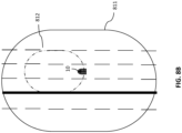
- FIG. 1 depicts an example environment where an EV alert management network is operated according to an exemplary embodiment of the present disclosure.
- an EV 10 communicates with a remote management server 20 through a communication network 15.
- the EV 10 may transmit EV-related data 11, a working mode selection signal 14 and/or the like to the remote management server 20.
- the remote management server 20 may communicate with each of other vehicles 30a to 30d which travel on roads nearby the EV 10 with a geofence.
- the EV 10 may directly communicate with the vehicles 30a to 30d by transmitting a geofence.
- a remote management server may generate a geofence based on EV-related data which are transmitted from the EV 10 and a size or shape of the geofence for an EV is varied based on a velocity of an EV.
- the remote management server 20 may generate a geofence (e.g., 84) based on the EV-related data transmitted from the EV 10 and transmit the geofence 84 to the vehicles 30a to 30d.
- the EV-related data 11 include a location of the vehicle, a velocity of the vehicle, and an ID of the EV 10.
- the EV 10 may generate a geofence (e.g., 81) based on the EV-related data and transmit the geofence to the other vehicles 30a to 30d.
- a geofence e.g., 81
- the present disclosure will primarily describe embodiments where the geofence is generated and transmitted by the remote management server 20 only for the sake of description. However, exemplary embodiments of the present disclosure are not limited thereto. Substantially the same or similar description given for the embodiments where the geofence is generated and transmitted by the remote management server 20 will be applied to the embodiments where the geofence is generated and transmitted by the EV 10. Duplicate thereof will be omitted for the sake of simplicity.
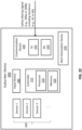
- FIG. 2A depicts a block diagram of an emergency subscriber device 100 according to an exemplary embodiment of the present disclosure.
- FIG. 2B depicts a block diagram of a remote management server 20 according to an exemplary embodiment of the present disclosure.
- FIG. 2C depicts a block diagram of a subscriber device 300 receiving an EV alert from the remote management server 20 according to an exemplary embodiment of the present disclosure.
- the emergency subscriber device 100 can be installed as a part of the EV 10, a wearable or portable device attached to the EV 10, or in the vicinity thereof.
- the subscriber device 300 can be installed as a part of each vehicle 30a to 30d, attached to the vehicle, or in the vicinity thereof.
- the geofence e.g., 84
- the remote management server 20 In this section will be described the embodiments where the geofence (e.g., 84) is generated and transmitted by the remote management server 20.
- the emergency subscriber device 100 includes a controller 115, a communication device 130, an input device 140, an output device 150, and one or more sensor devices 160.
- the controller 115 includes a processor 110 and a memory 120.
- the remote management server 20 includes a controller 215, a communication device 230, an input device 240, and an output device 250.
- the controller 215 includes a processor 210 and a memory 220.
- the remote management server 20 may reside on a network infrastructure or on a third-party service provider, such as a cloud storage and computing system. Further, referring to FIG.
- the subscriber device 300 includes a controller 315, a communication device 330, an input device 340, and an alert-generation device 370.
- the controller 315 includes a processor 310 and a memory 320.
- Each vehicle 30a to 30d may be a vehicle registered for services that provide emergency vehicle alerts, so that at least one of the above components thereof is designed to have features to receive the emergency vehicle alerts.
- the emergency subscriber device 100 generates EV-related data 11 and/or a working mode selection signal 14 and transmit the EV-related data 11 and/or the working mode selection signal 14 to the remote management server 20.
- the EV-related data 11 includes a type of the EV, a location of the EV, a velocity of the EV, or the like.
- the working mode selection signal 14 includes a working mode of the EV 10 which is selected (or determined). More details of the working mode selection signal 14 will be described with reference to FIGS. 4A and 4B .
- the remote management server 20 receives the EV-related data 11 and/or the working mode selection signal 14 using a receiver 234 of the communication device 230 transmitted over the communication network 15 and store the EV-related data 11 and/or the working mode selection signal 14 into the memory 220.
- the communication device 230 includes a transmitter 232 and the receiver 234.
- the communication device 230 may be implemented to support at least one of the above-mentioned communication techniques such as RFID, CDMA, GSM, wideband CDMA, CDMA2000 ® , TDMA, LTE, wireless LAN, Bluetooth ® , or the like.
- the input device 240 can be, but is not limited to: a keyboard, a touch screen, an audio input system, a voice recognition system, or the like.
- the output device 250 can be, but is not limited to: a screen, a speaker, a light, a siren, a visual system, an audio system, or the like.
- the remote management server 20 can perform one or more safety actions to provide an alert of the EV 10 to other vehicles 30a to 30d traveling on roads nearby the EV 10.
- the safety actions may include: determining a geofence based on the EV-related data 11, generating a safety warning signal (e.g., 500a of FIG. 3A or 500b of FIG. 3B ) based on the determined geofence; and transmitting the safety warning signal to the other vehicles 30a to 30d nearby the EV 10, more details of which will be described later.
- the safety warning signal 500a generated by the processor 210 of the remote management server 20 and transmitted to the subscriber device 300 of each vehicle 30a to 30d.
- the safety warning signal 500a includes, but is not limited to: an EV ID 510 and geofence information 520 related to the EV ID 510.
- the geofence information 520 can be any information used for identifying directly or indirectly features (e.g., size or shape) of the geofence for the EV 10.
- the geofence information 520 may be understood as a geofence, and thus, the geofence (e.g., 81, 84) is a part of the safety warning signal (e.g., 500a or 500b).
- the certain condition may include that a current location of each vehicle 30a to 30d is matched to a geofence defined by the geofence information.
- the geofence information 520 is directly provided as a set of location coordinates corresponding to a boundary of the determined geofence.
- the geofence information 520 is indirectly provided as an indication (e.g., geofence function G(x)) that can be used by the subscriber device 300 to retrieve the geofence from the geofence information 520, more details of which will be described with reference to FIG. 2C .
- a current location of the EV 10 may be provided in the safety warning signal 500a and/or safety warning signal 500b, so that the subscriber device 300 can combine the EV current location to generate a more exact geofence defined around the EV 10, and/or the subscriber device 300 tracks of the EV 10's movement based on the EV current location and displays on a visual system thereof.
- the indication can be an index identifying a specific geofence, and information regarding relationships between the indices and their respective mapping geofences can be prestored in the memory 320 of the subscriber device 300, so that the subscriber device 300 can read out an appropriate geofence based on the index.
- the safety warning signal 500a or 500b is transmitted to the subscriber device 300 of each vehicle 30a to 30d, and the processor 310 of the subscriber device 300 processes the geofence information 520 in the safety warning signal 500a or 500b to display the geofence through a display of the alert-generation device 370 of the subscriber device 300.
- the sensor devices 160 collects the EV-related data 11.
- the sensor data can be collected using sensor devices 160 including, but are not limited to: an accelerometer, a global positioning system (GPS) receiver, a velocity sensor, a motion sensor, infrared light sensors, radar, laser radar, cameras, a gyroscope, or the like.
- the collected EV-related data 11 may be stored in the memory 120 or other storage (not shown).
- the memory 120 includes program instructions executable by the processor 110 to perform functions or operations of the emergency subscriber device 100 described in the present disclosure.
- the processor 110 reads the stored data which have been collected from the sensor devices 160 and processes to generate messages that will be transmitted to the remote management server 20 through the transmitter 132 of the communication device 130.
- the communication device 130 may be implemented to support at least one of the above-mentioned communication techniques.
- the input device 140 can be, but is not limited to: a keyboard, a touch screen, an audio input system, a voice recognition system, or the like.
- the output device 150 can be, but is not limited to: a screen, a speaker, a light, a siren, a visual system, an audio system, or the like.
- the communication device 330 includes a transmitter 332 and a receiver 334 which are implemented to support at least one of the above-mentioned communication techniques being capable of communicating with the communication device 230 of the remote management server 20 and/or the communication device 130 of the EV 10.
- the safety warning signal 500a or 500b received through the receiver 334 may be stored in the memory 320.
- the processor 310 may retrieve a geofence for the EV 10 based on the safety warning signal 500a or 500b.
- the processor 310 of the subscriber device 300 determines whether a current location of the corresponding vehicle is matched to the geofence of the EV 10 based on the set of location coordinates in the geofence information 520. For example, if the current location of each vehicle 30a to 30d is within the boundary defined by the set of location coordinates, the processor 310 determines a match between the vehicle current location and the geofence; otherwise, it determines a mismatch therebetween.
- the processor 310 further retrieves the geofence based on the geofence information 520 (e.g., based on the geofence function G(x)), and then determines whether the vehicle current location is located within the geofence or not. If a match is found between the current location and the geofence, the processor 310 controls the alert-generation device 370 to perform one or more alert actions; otherwise (e.g., if no match is found therebetween) the processor 310 discards the safety warning signal 500a or 500b and performs no further action for providing the EV alert.
- the processor 310 determines whether the vehicle current location is located within the geofence or not. If a match is found between the current location and the geofence, the processor 310 controls the alert-generation device 370 to perform one or more alert actions; otherwise (e.g., if no match is found therebetween) the processor 310 discards the safety warning signal 500a or 500b and performs no further action for providing the EV alert.
- the alert-generation device 370 is configured to perform alert actions under control of the processor 310.
- the alert-generation device 370 can be, but is not limited to: a screen, a speaker, a light, a siren, a visual system, an audio system, or the like.
- the input device 340 can be, but is not limited to: a keyboard, a touch screen, an audio input system, a voice recognition system, or the like.
- the current location can be collected using the sensor devices 360 such as a positioning device, as shown in FIG. 2C .
- the alert actions include generating a visual and/or audible warning signal for a driver to recognize an EV alert for next safety actions such as yielding for the EV to let the EV safely pass.
- the alert actions are preprogrammed and stored in the memory 320 of the subscriber device 300, and when a match is found between the current location and the geofence, the processor 310 reads the alert actions from the memory 320 to control the alert-generation device 370 to perform the alert actions.
- the alert actions are transferred from the remote management server 20 to the subscriber device 300 of each vehicle 30a to 30d through the alert action information field 520 in the safety warning signal 500b, as depicted in FIG. 3B .
- the processor 310 controls the alert-generation device 370 to perform the alert actions, as instructed in the alert action information field 540.
- the geofence can dynamically be adjusted in size or shape according to a working mode of the EV 10.
- the processor 210 of the remote management server 20 dynamically changes the shape or size of the geofence based on the working mode of the EV 10.
- the working mode of the EV 10 can be selected (or determined) at the EV 10 or the remote management server 20. In case the working mode is selected at the EV 10, the selected working mode is provided in the working mode selection signal 14 and transmitted to the remote management server 20 over the communication network 15.
- the working mode includes a normal mode and one or more emergency modes.
- a normal mode it may be understood that the EV 10 does not perform any mission associated with the emergency situation; in this case, no geofence may be generated, or a geofence of a minimum size (e.g., G N (x)) may be generated.
- G N (x) a geofence of a minimum size
- the EV 10 performs emergency actions(s) (with an intent) associated with the emergency situation.
- a geofence having a larger size than the geofence G N (x) is generated and transmitted, so that the EV 10 can travel more safely.
- the emergency modes may have different degrees of emergencies one from another, and different sizes or shapes of geofences may be generated and transmitted for the respectively emergency modes having different degrees of emergencies. For example, as the working mode is changed from an emergency mode having the lowest degree of emergency to an emergency mode having the highest degree of emergency, the size of a corresponding geofence to be generated and transmitted is increased accordingly, or vice versa.
- the working mode of the EV 10 can be selected (or determined) in a manual manner by a user selection input through an input device 140 of the emergency subscriber device 100, which will be described with reference to FIG. 4A .
- information on the emergency situation may be collected by one or more network devices (not shown) and shared with the remote management server 20 and the EV 10 through the communication network 15. If the EV 10 receives the information on the emergency situation, it may transmit the same to the emergency subscriber device 100 of the EV 10. Examples of the information on the emergency situation, but are not limited: a location or time where the emergency situation has occurred, a content (e.g., car accident, fire, natural disaster, robbery, etc.) of the emergency situation, the number of deaths or injuries, or the like.
- a content e.g., car accident, fire, natural disaster, robbery, etc.
- FIG. 4A depicts a flow chart of a method for selecting a working mode of an EV and varying a size or shape of a geofence based on the selected working mode according to an exemplary embodiment of the present disclosure.
- the working mode selection of the EV 10 is made in a manual manner by a user selection input through the input device 140 of the emergency subscriber device 100.
- the emergency subscriber device 100 e.g., processor 110
- the emergency subscriber device 100 may display an operator of the EV (e.g., driver) the information of the emergency situation using the output device 150 (e.g., display screen) (S420) and allow the EV operator to select (or input) one of emergency modes through the input device 140.
- the emergency subscriber device 100 receives a user selection input for the working mode of the EV 10 (S430).
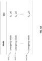
- selection menu for the working mode is depicted in FIG. 5 .
- the selection menu may include a specific button, or the like which allows the user to select a working mode in which he wants to operate the EV 10.
- the selection menu may include, but are not limited: a normal mode 1410_0, one or more emergency modes 1410_1 to 1410_M and/or one or more intents 1420_1 to 1420_N.
- M and N are integers each equal to or more than one.
- the emergency subscriber device 100 Upon selecting one of the menu by a user (e.g., an operator of the EV 10), the emergency subscriber device 100 (e.g., processor 110) generates a working mode selection signal 14 that indicates the working mode corresponding to the selected menu (S440) and transmits the working mode selection signal 14 to the remote management server 20 using the transmitter 132 (S450).
- the remote management server 20 e.g., processor 210) varies a size or shape of a geofence for the EV 10 based on the working mode provided in the working mode selection signal 14, when it determines the geofence (S460).
- the working mode selection signal 14 indicating that the EV 10 is in the normal mode is transmitted to the remote management server 20, and the processor 210 of the remote management server 20 determines a geofence (e.g., G N (x)), generates a safety warning signal based on the geofence G N (x), and transmits the safety warning signal to the other vehicles 30a to 30d nearby the EV 10.
- a geofence e.g., G N (x)
- G N (x) e.g., G N (x)
- the safety warning signal e.g., G N (x)
- the selection menu of the input device 140 of FIG. 2A might not include the normal mode, so it may be conceivable that the normal mode is set as a default mode if none of the emergency modes 1410_1 to 1410_M and intents 1420_1 to 1420_N is selected.
- the operator of the EV may determine a degree of emergency for an emergency situation based on the information of the emergency situation displayed on the output device 150 and select an emergency mode (among the emergency modes 1410_1 to 1410_M) corresponding to the determined degree of emergency.
- the working mode selection signal 14 indicating that the EV 10 is in the particular emergency mode is transmitted to the remote management server 20, and the processor 210 of the remote management server 20 determines a geofence corresponding to the particular emergency mode, generates a safety warning signal based on the geofence, and transmits the safety warning signal to the other vehicles 30a to 30d nearby the EV 10.
- FIG. 6A depicts an example mapping relationship among multiple emergency modes, and geofence functions according to an exemplary embodiment of the present disclosure.
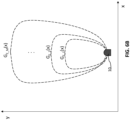
- FIG. 6B depicts example geofence functions of FIG. 6A according to an exemplary embodiment of the present disclosure.
- the emergency modes 1410_1 to 1410_M have different degrees of emergencies one from another which are respectively mapped to different geofence functions G E _1(x) to G E_M (x).
- G E _1(x) the geofence functions
- G E_M the geofence functions
- the degree of emergency increases, and thus, the size of corresponding geofence is increased from the geofence G E_1 (x) to G E_M (x).
- FIG. 6B Although it is illustrated in FIG. 6B that shapes of the geofences are similar to one to another, exemplary embodiments of the present disclosure are not limited thereto. For example, the shapes thereof can be varied if necessary.
- the EV operator may directly determine and select a particular intent from among the intents 1420_1 to 1420_N based on the information of the emergency situation displayed on the output device 150.
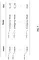
- FIG. 7 depicts an example mapping relationship among intents, emergency modes, and geofence functions according to an exemplary embodiment of the present disclosure.
- a certain intent e.g., 1420_1 is associated with one (e.g., 1410_1) of the emergency modes 1410_1 to 1410_M, so that upon selecting such intent (e.g., 1420_1), the working mode selection signal 14 indicating that the EV 10 is in the emergency mode (e.g., 1410_1) is transmitted to the remote management server 20, and the processor 210 of the remote management server 20 determines a geofence corresponding to the emergency mode (e.g., 1410_1), generates a safety warning signal based on the geofence, and transmits the safety warning signal to the other vehicles 30a to 30d nearby the EV 10.
- the emergency mode e.g., 1410_1
- another intent is not associated with any of the emergency modes 1410_1 to 1410_M.
- the working mode selection signal 14 indicating that the EV 10 is in an emergency mode e.g., 1410_K
- the processor 210 of the remote management server 20 determines a geofence (e.g., G K (x) corresponding to the emergency mode (e.g., 1410_K)
- the processor 210 of the remote management server 20 determines a geofence (e.g., G K (x) corresponding to the emergency mode (e.g., 1410_K)
- the emergency mode e.g., 1410_K
- the emergency mode 1410_K might not be among the emergency modes 1410_1 to 1410_M, for example, no degree of emergency might be assigned to the emergency mode 1410_K unlike the emergency modes 1410_1 to 1410_M, and a corresponding geofence G K (x) might have a different size or shape from each of the geofences G E_1 (x) to G E_M (x).
- the selection menu includes both the emergency modes 1410_1 to 1410_M and the intents 1420_1 to 1420_N
- exemplary embodiments of the present disclosure are not limited thereto.
- the system allows only one group of the emergency modes 1410_1 to 1410_M and the intents 1420_1 to 1420_N to be used for the working mode selection of the EV 10, so that either of the emergency modes 1410_1 to 1410_M and the intents 1420_1 to 1420_N might not be shown or provided in the selection menu of FIG. 5 .
- the working mode of the EV 10 can be selected (or determined) in an automatic manner by the emergency subscriber device 100 of the EV 10, which will be described with reference to FIG. 4B .
- FIG. 4B depicts a flow chart of a method for selecting a working mode of an EV and varying a size or shape of a geofence based on the selected working mode according to an exemplary embodiment of the present disclosure.
- the working mode selection of the EV 10 is made in an automatic manner by the emergency subscriber device 100 (e.g., the processor 110) based on the information on the emergency situation.
- the processor 110 receives the information on the emergency situation from the remote management server 20 or other control systems which receive various information regarding emergency situations.
- the processor 110 determines a working mode based on the information of the emergency situation (S520), generates a working mode selection signal 14 indicating the determined working mode (S530), and transmits the working mode selection signal 14 to the remote management server 20 using the transmitter 132 (S540).
- the remote management server 20 e.g., processor 210) varies a size or shape of a geofence for the EV 10 based on the working mode provided in the working mode selection signal 14, when it determines the geofence.
- the memory 120 stores information on a mapping relationship (not shown) between the information of the emergency situation and a desired working mode in which the EV 10 is expected to work.
- the processor 110 uses the mapping relationship to determine the working mode based on the information of the emergency situation.
- the processor 110 and the memory 120 may be implemented using a machine learning system (e.g., artificial intelligence platform) (not shown) which allows for selecting (or determining) a working mode of the EV 10 based on the information on the emergency situation.
- the machine learning system can be embodied based on at least one machine learning algorithm of an artificial neural network (ANN), recurrent neural network (RNN) including long short-term memory (LSTM) (i.e., a LSTM network), a support vector machine, a decision tree, a deep learning, a sparse network of winnows (SNoW), a K-nearest neighbor, a Naive Bayes, or the like, or any combination thereof.
- ANN artificial neural network
- RNN recurrent neural network
- LSTM long short-term memory
- SNoW sparse network of winnows
- K-nearest neighbor e.g., K-nearest neighbor
- Naive Bayes e.g., Naive Bayes,
- a police officer is stopped on the side of the road and places our control system in a state that is signaling motorists to the left of the vehicle, a officer initiated geofence is created. Further, the system can increase the degree of geo fence when the driver side door is opened and the driver seat sensor is signaling vacant. The geo fence severity therefore is signal the physical obstacle of the parked EV AND that an Officer is outside the vehicle and presumably in the road or on the roadside.
- examples of the intents 1420_1 to 1420_N may include, but are not limited: chasing or pursuing of criminal(s), emergency responding to the scene, safety actions for other stopping vehicles, pulling over vehicles, or the like if the EV 10 is a police car; emergency responding to the scene, transferring patients toward a hospital, or the like if the EV 10 is an ambulance; emergency responding to the scene, extinguishing fire, rescuing people or the like if the EV 10 is a fire truck or a rescue vehicle; roadside removal or assistance of a disabled vehicle in the case of a tow truck or motorist aid vehicle.
- FIG. 8A depicts example classifications of the intents depending on a moving status of the EV according to an exemplary embodiment of the present application.
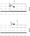
- FIGS. 8B to 8E depict example geofences for the EV depending on the intents thereof according to an exemplary embodiment of the present application.
- the geofence 811 can be extended to cover as broad an area as possible which allows for providing an alert to as many vehicles or people as possible, so that the other vehicles can stay away from the scene.
- the geofence 811 may be broadened up to the opposing lanes.
- the geofence 812 can be generated to cover a front direction of the EV 10 rather than a rear direction thereof and the size of the geofence 812 can be smaller than that of the geofence 811.
- safety warning signals generated by the processor 110 of the emergency subscriber device 100 and transmitted to the subscriber device 300 are substantially the same as or similar to the safety warning signals 500a or 500b described with reference to FIGS. 3A and 3B .
- the memory 120 includes program instructions executable by the processor 110 to perform functions or operations of the emergency subscriber device 100 described in the present disclosure.
- the processor 110 reads the stored data which have been collected from the sensor devices 160 and processes to generate messages that will be transmitted to the subscriber device 300 through the transmitter 132 of the communication device 130.
- FIG. 9A depicts a flow chart of a method for selecting a working mode of an EV and varying a size or shape of a geofence based on the selected working mode according to an exemplary embodiment of the present disclosure.
- the emergency subscriber device 100 receives a user selection input for the working mode of the EV 10 (S830).
- the EV 10 e.g., processor 110
- the EV 10 varies a size or shape of a geofence for the EV 10 based on the selected working mode, when it determines the geofence (S840).
- FIG. 10 is a block diagram of a computing system 4000 according to an exemplary embodiment of the present disclosure.
- the computing system 4000 may include a processor 4010, I/O devices 4020, a memory system 4030, a display device 4040, and/or a network adaptor 4050.
- the computing system 4000 may include a program module for performing: the functions or operations described hereinabove with respect to at least one of the emergency subscriber device 100, the remote management server 20 and the subscriber device 300; and the methods described with reference to FIGS. 2A-2C , 3A-3B , 4A-4B , 5 , 8A-8E and 9A-9B .
- the program module may include routines, programs, objects, components, logic, data structures, or the like, for performing particular tasks or implement particular abstract data types.
- the computing system 4000 may include a variety of computing system readable media. Such media may be any available media that is accessible by the computer system (e.g., 4000), and it may include both volatile and non-volatile media, removable and non-removable media.
- the memory system (e.g., 4030) can include computer system readable media in the form of volatile memory, such as RAM and/or cache memory or others.
- the computer system (e.g., 4000) may further include other removable/non-removable, volatile/non-volatile computer system storage media.
- Exemplary embodiments of the present disclosure may include a system, a method, and/or a non-transitory computer readable storage medium.
- the non-transitory computer readable storage medium e.g., the memory system 4030
- a non-exhaustive list of more specific examples of the computer readable storage medium includes the following: a portable computer diskette, a hard disk, a random access memory (RAM), a read-only memory (ROM), an erasable programmable read-only memory (EEPROM or Flash memory), a static random access memory (SRAM), a portable compact disc read-only memory (CD-ROM), a digital versatile disk (DVD), a memory stick, a floppy disk, or the like, a mechanically encoded device such as punch-cards or raised structures in a groove having instructions recorded thereon, and any suitable combination of the foregoing.
- RAM random access memory
- ROM read-only memory
- EEPROM or Flash memory erasable programmable read-only memory
- SRAM static random access memory
- CD-ROM compact disc read-only memory
- DVD digital versatile disk
- memory stick a floppy disk, or the like
- a mechanically encoded device such as punch-cards or raised structures in a groove having instructions recorded thereon
- a computer readable storage medium is not to be construed as being transitory signals per se, such as radio waves or other freely propagating electromagnetic waves, electromagnetic waves propagating through a waveguide or other transmission media (e.g., light pulses passing through a fiber-optic cable), or electrical signals transmitted through a wire.
- Computer readable program instructions described herein can be downloaded to the computing system 4000 from the computer readable storage medium or to an external computer or external storage device via a network.
- the network may include copper transmission cables, optical transmission fibers, wireless transmission, routers, firewalls, switches, gateway computers and/or edge servers.
- a network adapter card (e.g., 4050) or network interface in each computing/processing device receives computer readable program instructions from the network and forwards the computer readable program instructions for storage in a computer readable storage medium within the computing system.
- Computer readable program instructions for carrying out operations of the present disclosure may be assembler instructions, instruction-set-architecture (ISA) instructions, machine instructions, machine dependent instructions, microcode, firmware instructions, state-setting data, or either source code or object code written in any combination of one or more programming languages, including an object oriented programming language such as Smalltalk, C++ or the like, and conventional procedural programming languages, such as the "C" programming language or similar programming languages.
- the computer readable program instructions may execute entirely on the user's computer, partly on the user's computer, as a stand-alone software package, partly on the user's computer and partly on a remote computer or entirely on the remote computer or server.
- the remote computer may be connected to the computing system (e.g., 4000) through any type of network, including a LAN or a WAN, or the connection may be made to an external computer (for example, through the Internet using an Internet Service Provider).
- electronic circuitry including, for example, programmable logic circuitry, field-programmable gate arrays (FPGA), or programmable logic arrays (PLA) may execute the computer readable program instructions by utilizing state information of the computer readable program instructions to personalize the electronic circuitry, in order to perform aspects of the present disclosure.
- These computer readable program instructions may be provided to a processor of a general-purpose computer, special purpose computer, or other programmable data processing apparatus to produce a machine, such that the instructions, which execute via the processor of the computer or other programmable data processing apparatus, create means for implementing the functions/acts specified in the flowchart and/or block diagram block or blocks.
- These computer readable program instructions may also be stored in a computer readable storage medium that can direct a computer, a programmable data processing apparatus, and/or other devices to function in a particular manner, such that the computer readable storage medium having instructions stored therein comprises an article of manufacture including instructions which implement aspects of the function/act specified in the flowchart and/or block diagram block or blocks.
- the computer readable program instructions may also be loaded onto a computer, other programmable data processing apparatus, or other device to cause a series of operational steps to be performed on the computer, other programmable apparatus or other device to produce a computer implemented process, such that the instructions which execute on the computer, other programmable apparatus, or other device implement the functions/acts specified in the flowchart and/or block diagram block or blocks.
- each block in the flowchart or block diagrams may represent a module, segment, or portion of instructions, which comprises one or more executable instructions for implementing the specified logical function(s).
- the functions noted in the block may occur out of the order noted in the figures.
- two blocks shown in succession may, in fact, be executed substantially concurrently, or the blocks may sometimes be executed in the reverse order, depending upon the functionality involved.
Landscapes
- Engineering & Computer Science (AREA)
- Physics & Mathematics (AREA)
- General Physics & Mathematics (AREA)
- Theoretical Computer Science (AREA)
- Signal Processing (AREA)
- Computer Networks & Wireless Communication (AREA)
- Software Systems (AREA)
- Emergency Management (AREA)
- Artificial Intelligence (AREA)
- General Engineering & Computer Science (AREA)
- Computing Systems (AREA)
- Mathematical Physics (AREA)
- Evolutionary Computation (AREA)
- Health & Medical Sciences (AREA)
- Data Mining & Analysis (AREA)
- Business, Economics & Management (AREA)
- Biophysics (AREA)
- Computational Linguistics (AREA)
- General Health & Medical Sciences (AREA)
- Molecular Biology (AREA)
- Biomedical Technology (AREA)
- Life Sciences & Earth Sciences (AREA)
- Computer Vision & Pattern Recognition (AREA)
- Medical Informatics (AREA)
- Environmental & Geological Engineering (AREA)
- Public Health (AREA)
- Alarm Systems (AREA)
- Traffic Control Systems (AREA)
- Catching Or Destruction (AREA)
- Pretreatment Of Seeds And Plants (AREA)
Claims (23)
- System zum Vorsehen eines Notfallfahrzeug-, EV-,Warnsignals, das aufweist:mehrere Sensoren (160), die ausgestaltet sind, EV-bezogene Daten zu sammeln, einschließlich Daten, die sich auf wenigstens einen Betriebsstatus und einen Belegtstatus eines Notfallfahrzeugs (10) beziehen;einen Prozessor (110), der konfiguriert ist, einen Geofence für das Notfallfahrzeug (10) zu erzeugen, und konfiguriert ist, eine Form oder Größe des erzeugten Geofence in Abhängigkeit von einem Arbeitsmodus des Notfallfahrzeugs (10) zu variieren,eine bestimmte Absicht, die mit dem Notfallfahrzeug (10) und den auf das Notfallfahrzeug-bezogenen Daten verknüpft ist; undeinen Sender (132), der konfiguriert ist, den erzeugten Geofence zu übertragen.wobei der Arbeitsmodus einen Nicht-Notfallmodus und wenigstens einen Notfallmodus aufweist, und wobei die Absicht basierend auf einem Bewegungsstatus des Notfallfahrzeugs (10) bestimmt wird.
- System nach Anspruch 1, das weiterhin ein anderes Fahrzeug (30a, 30b, 30c, 30d) aufweist,wobei der andere Prozessor (310), der mit dem anderen Fahrzeug (30a, 30b, 30c, 30d) verknüpft ist, dazu konfiguriert ist,den Geofence zu empfangen;eine Position des anderen Fahrzeugs (30a, 30b, 30c, 30d) bezüglich des Geofence zu bestimmen; undeine oder mehrere Warnaktionen basierend auf der bestimmten Position des anderen Fahrzeugs (30a, 30b, 30c, 30d) bezüglich des empfangenen Geofence durchzuführen.
- System nach Anspruch 1, wobei der Prozessor (110) weiterhin konfiguriert ist, den Arbeitsmodus des Notfallfahrzeugs (10) basierend auf einer Auswahleingabe durch einen Bediener oder Programmanweisungen, die in einem Speicher (120) gespeichert sind und durch einen Prozessor (110) ausführbar sind, zu bestimmen, und
wobei die Programmanweisungen bei Ausführung durch den Prozessor (110) den Arbeitsmodus basierend auf Informationen zu einer Notfallsituation, die über ein Kommunikationsnetzwerk (15) empfangen wurden, bestimmen. - System nach Anspruch 1, das weiterhin eine Eingabeschnittstelle aufweist, die konfiguriert ist:die Auswahleingabe entsprechend einem von dem Nicht-Notfallmodus und den Notfallmodi zu empfangen; unddie Auswahleingabe an den Prozessor (110) zu übertragen.
- System nach Anspruch 1, wobei der Prozessor (110) weiterhin konfiguriert ist, die Größe des Geofence zu erhöhen, wenn der Arbeitsmodus vom Nicht-Notfallmodus in einen der Notfallmodi geändert wird.
- System nach Anspruch 1, wobei der Prozessor (110) weiterhin konfiguriert ist, die Größe oder Form des Geofence zu erhöhen, wenn der Arbeitsmodus zwischen den Notfallmodi geändert wird.
- System nach Anspruch 1, wobei der Prozessor (110) weiter konfiguriert ist, die Größe des Geofence zu erhöhen, wenn sich der Arbeitsmodus von einem der Notfallmodi, die einen ersten Notfallgrad haben, in einen anderen der Notfallmodi ändert, die einen zweiten Notfallgrad haben, der höher als der erste Notfallgrad ist.
- System nach Anspruch 4, wobei die Eingabeschnittstelle ein oder mehrere Auswahlmenüs aufweist, die mit den Notfallmodi verknüpft sind.
- System nach Anspruch 3, wobei der Prozessor (110) und der Speicher (120), der Programmanweisungen speichert, unter Verwendung eines Maschinenlernsystems zum Bestimmen des Arbeitsmodus des Notfallfahrzeugs (10) implementiert werden.
- System nach Anspruch 1, wobei der Prozessor (110) und der Sender (132) sich in der Nähe des Notfallfahrzeugs (10) befinden oder darin enthalten sind.
- System nach Anspruch 1, wobei der Prozessor (110) und der Sender (132) sich in der Nähe des Notfallfahrzeugs (10) befinden oder in einem Managementserver enthalten sind, der sich entfernt vom Notfallfahrzeug (10) befindet.
- Verfahren zum Vorsehen eines Notfallfahrzeug-, EV-,Warnsignals, das aufweist:Sammeln mit mehreren Sensoren (160) von EV-bezogenen Daten, einschließlich Daten, die sich auf wenigstens einen Betriebsstatus und einen Belegtstatus eines Notfallfahrzeugs (10) beziehen;Bestimmen einer Absicht, die mit dem Notfallfahrzeug (10) verknüpft ist, basierend auf einem Bewegungsstatus des Notfallfahrzeugs (10);Erzeugen durch einen Prozessor (110) eines Geofence und Variieren einer Form oder Größe des erzeugten Geofence in Abhängigkeit von einem Arbeitsmodus des Notfallfahrzeugs (10), der bestimmten Absicht und den Notfallfahrzeug-bezogenen Daten; undÜbertragen durch einen Sender (132) des generierten Geofence,wobei der Arbeitsmodus einen Nicht-Notfallmodus und wenigstens einen Notfallmodus aufweist.
- Verfahren nach Anspruch 12, das weiterhin aufweist:Empfangen des Geofence durch einen mit dem anderen Fahrzeug (30a, 30b, 30c, 30d) verknüpften anderen Prozessor (310);Bestimmen durch den anderen Prozessor (310) einer Position des anderen Fahrzeugs (30a, 30b, 30c, 30d) bezüglich des empfangenen Geofence; undDurchführen durch den anderen Prozessor (310) von einer oder mehreren Warnaktionen basierend auf der bestimmten Position des anderen Fahrzeugs (30a, 30b, 30c, 30d) bezüglich des empfangenen Geofence.
- Verfahren nach Anspruch 12, das weiterhin aufweist:Bestimmen des Arbeitsmodus des Notfallfahrzeugs (10) basierend auf einer Auswahleingabe durch einen Bediener oder Programmanweisungen, die in einem Speicher (120) gespeichert sind und durch einen Prozessor (110) ausführbar sind,wobei die Programmanweisungen bei Ausführung durch den Prozessor (110) den Arbeitsmodus basierend auf Informationen zu einer Notfallsituation, die über ein Kommunikationsnetzwerk (15) empfangen wurden, bestimmen.
- Verfahren nach Anspruch 12, das weiterhin aufweist:Empfangen der Auswahleingabe, die einem von dem Nicht-Notfallmodus und den Notfallmodi entspricht, unter Verwendung einer Eingabeschnittstelle; undÜbertragen der Auswahleingabe an den Prozessor (110).
- Verfahren nach Anspruch 12, das weiterhin aufweist:
Erhöhen durch den Prozessor (110) der Größe des Geofence, wenn der Arbeitsmodus vom Nicht-Notfallmodus in einen der Notfallmodi geändert wird. - Verfahren nach Anspruch 12, das weiterhin aufweist:
Variieren durch den Prozessor (110) der Größe oder Form des Geofence, wenn der Arbeitsmodus zwischen den Notfallmodi geändert wird. - Verfahren nach Anspruch 12, das weiterhin aufweist:
Erhöhen durch den Prozessor (110) der Größe des Geofence, wenn sich der Arbeitsmodus von einem der Notfallmodi, die einen ersten Notfallgrad haben, in einen anderen der Notfallmodi ändert, die einen zweiten Notfallgrad haben, der höher als der erste Notfallgrad ist. - Computer-lesbares Speichermedium, das Computer-lesbare Programmanweisungen hat, wobei die Computer-lesbaren Programmanweisungen von wenigstens einem Prozessor (110) zum Durchführen eines Verfahrens zum Bereitstellen eines Notfallfahrzeugs (10) gelesen und ausgeführt werden, das aufweist:Empfangen über mehrere Sensoren (160) von EV-bezogenen Daten, die Daten aufweisen, die sich auf wenigstens einen Betriebsstatus und einen Belegtstatus eines Notfallfahrzeugs (10) beziehen;Erzeugen eines Geofence und Variieren einer Form oder Größe des erzeugten Geofence in Abhängigkeit von einem Arbeitsmodus des Notfallfahrzeugs (10), einer mit dem Notfallfahrzeug (10) verknüpften bestimmten Absicht und den Notfallfahrzeug-bezogenen Daten; undÜbertragen des erzeugten Geofence;wobei der Arbeitsmodus einen Nicht-Notfallmodus und wenigstens einen Notfallmodus aufweist, und wobei die Absicht basierend auf einem Bewegungsstatus des Notfallfahrzeugs (10) bestimmt wird.
- Speichermedium nach Anspruch 19, wobei das Verfahren weiterhin aufweist:Empfangen der Auswahleingabe entsprechend einem von dem Nicht-Notfallmodus und der Notfallmodi unter Verwendung einer Eingabeschnittstelle; undÜbertragen der Auswahleingabe an den wenigstens einen Prozessor (110).
- Speichermedium nach Anspruch 19, wobei das Verfahren weiterhin aufweist:
Erhöhen der Größe des Geofence, wenn der Arbeitsmodus vom Nicht-Notfallmodus in einen der Notfallmodi geändert wird. - Speichermedium nach Anspruch 19, wobei das Verfahren weiterhin aufweist:
Variieren der Größe oder Form des Geofence, wenn der Arbeitsmodus zwischen den Notfallmodi geändert wird. - Speichermedium nach Anspruch 19, wobei das Verfahren weiterhin aufweist:
Erhöhen der Größe des Geofence, wenn sich der Arbeitsmodus von einem der Notfallmodi, die einen ersten Notfallgrad haben, in einen anderen von den Notfallmodi ändert, die einen zweiten Notfallgrad haben, der höher als der erste Notfallgrad ist.
Priority Applications (1)
| Application Number | Priority Date | Filing Date | Title |
|---|---|---|---|
| EP25152083.9A EP4531445A3 (de) | 2019-10-15 | 2019-10-15 | System und verfahren für absichtsbasiertes geofencing für ein notfahrzeug |
Applications Claiming Priority (1)
| Application Number | Priority Date | Filing Date | Title |
|---|---|---|---|
| PCT/US2019/056340 WO2021076112A1 (en) | 2019-10-15 | 2019-10-15 | System and method for intent-based geofencing for emergency vehicle |
Related Child Applications (2)
| Application Number | Title | Priority Date | Filing Date |
|---|---|---|---|
| EP25152083.9A Division-Into EP4531445A3 (de) | 2019-10-15 | 2019-10-15 | System und verfahren für absichtsbasiertes geofencing für ein notfahrzeug |
| EP25152083.9A Division EP4531445A3 (de) | 2019-10-15 | 2019-10-15 | System und verfahren für absichtsbasiertes geofencing für ein notfahrzeug |
Publications (2)
| Publication Number | Publication Date |
|---|---|
| EP4046400A1 EP4046400A1 (de) | 2022-08-24 |
| EP4046400B1 true EP4046400B1 (de) | 2025-03-05 |
Family
ID=68425372
Family Applications (2)
| Application Number | Title | Priority Date | Filing Date |
|---|---|---|---|
| EP25152083.9A Pending EP4531445A3 (de) | 2019-10-15 | 2019-10-15 | System und verfahren für absichtsbasiertes geofencing für ein notfahrzeug |
| EP19797529.5A Active EP4046400B1 (de) | 2019-10-15 | 2019-10-15 | Vorrichtung und verfahren zum absichtsbasierten geofencing für einsatzfahrzeuge |
Family Applications Before (1)
| Application Number | Title | Priority Date | Filing Date |
|---|---|---|---|
| EP25152083.9A Pending EP4531445A3 (de) | 2019-10-15 | 2019-10-15 | System und verfahren für absichtsbasiertes geofencing für ein notfahrzeug |
Country Status (4)
| Country | Link |
|---|---|
| EP (2) | EP4531445A3 (de) |
| ES (1) | ES3028256T3 (de) |
| PL (1) | PL4046400T3 (de) |
| WO (1) | WO2021076112A1 (de) |
Families Citing this family (1)
| Publication number | Priority date | Publication date | Assignee | Title |
|---|---|---|---|---|
| CN114401487A (zh) * | 2022-01-27 | 2022-04-26 | 深圳市中云慧通科技有限公司 | 一种应急场景下人员定位、通信确定方法及存储介质 |
Family Cites Families (4)
| Publication number | Priority date | Publication date | Assignee | Title |
|---|---|---|---|---|
| US10127813B2 (en) * | 2015-01-20 | 2018-11-13 | Invent F&W, Llc | Systems and methods for alerting drivers of approaching emergency vehicles |
| US9833891B2 (en) | 2015-02-23 | 2017-12-05 | James Patterson | Anti-torqueing dynamic arresting mechanism |
| US9688288B1 (en) * | 2016-03-08 | 2017-06-27 | VOLKSWAGEN AG et al. | Geofencing for auto drive route planning |
| WO2019144090A1 (en) * | 2018-01-22 | 2019-07-25 | RPMAnetworks Holding | System and method of two-way wireless communication for connected car vehicle |
-
2019
- 2019-10-15 EP EP25152083.9A patent/EP4531445A3/de active Pending
- 2019-10-15 WO PCT/US2019/056340 patent/WO2021076112A1/en not_active Ceased
- 2019-10-15 EP EP19797529.5A patent/EP4046400B1/de active Active
- 2019-10-15 ES ES19797529T patent/ES3028256T3/es active Active
- 2019-10-15 PL PL19797529.5T patent/PL4046400T3/pl unknown
Also Published As
| Publication number | Publication date |
|---|---|
| EP4531445A3 (de) | 2025-04-30 |
| WO2021076112A1 (en) | 2021-04-22 |
| EP4046400A1 (de) | 2022-08-24 |
| ES3028256T3 (en) | 2025-06-18 |
| PL4046400T3 (pl) | 2025-08-11 |
| EP4531445A2 (de) | 2025-04-02 |
Similar Documents
| Publication | Publication Date | Title |
|---|---|---|
| US12574703B2 (en) | System and method for intent-based geofencing for emergency vehicle | |
| US9463875B2 (en) | Unmanned aerial vehicle for hazard detection | |
| US11265675B2 (en) | System and method for managing emergency vehicle alert geofence | |
| US20250088823A1 (en) | System and method for velocity-based geofencing for emergency vehicle | |
| US11900804B2 (en) | System and method for map-based geofencing for emergency vehicle | |
| US12160808B2 (en) | System and method for operating stealth mode of emergency vehicle | |
| EP4046400B1 (de) | Vorrichtung und verfahren zum absichtsbasierten geofencing für einsatzfahrzeuge | |
| EP3935613B1 (de) | Systeme und verfahren für kartenbasiertes geofencing | |
| EP3909032B1 (de) | System und verfahren für geschwindigkeitsbasiertes geofencing für ein rettungsfallfahrzeug | |
| US20190236945A1 (en) | Vehicle Alarm System, Alarm Device and Alarm Method Thereof | |
| WO2020185205A1 (en) | Systems and method for clearing a geofence | |
| EP3939223B1 (de) | Verfahren und system zur stealth-modusbetrieb eines einsatzfahrzeug |
Legal Events
| Date | Code | Title | Description |
|---|---|---|---|
| STAA | Information on the status of an ep patent application or granted ep patent |
Free format text: STATUS: UNKNOWN |
|
| STAA | Information on the status of an ep patent application or granted ep patent |
Free format text: STATUS: THE INTERNATIONAL PUBLICATION HAS BEEN MADE |
|
| PUAI | Public reference made under article 153(3) epc to a published international application that has entered the european phase |
Free format text: ORIGINAL CODE: 0009012 |
|
| STAA | Information on the status of an ep patent application or granted ep patent |
Free format text: STATUS: REQUEST FOR EXAMINATION WAS MADE |
|
| 17P | Request for examination filed |
Effective date: 20220411 |
|
| AK | Designated contracting states |
Kind code of ref document: A1 Designated state(s): AL AT BE BG CH CY CZ DE DK EE ES FI FR GB GR HR HU IE IS IT LI LT LU LV MC MK MT NL NO PL PT RO RS SE SI SK SM TR |
|
| DAV | Request for validation of the european patent (deleted) | ||
| DAX | Request for extension of the european patent (deleted) | ||
| P01 | Opt-out of the competence of the unified patent court (upc) registered |
Effective date: 20230524 |
|
| GRAP | Despatch of communication of intention to grant a patent |
Free format text: ORIGINAL CODE: EPIDOSNIGR1 |
|
| STAA | Information on the status of an ep patent application or granted ep patent |
Free format text: STATUS: GRANT OF PATENT IS INTENDED |
|
| INTG | Intention to grant announced |
Effective date: 20241127 |
|
| GRAS | Grant fee paid |
Free format text: ORIGINAL CODE: EPIDOSNIGR3 |
|
| GRAA | (expected) grant |
Free format text: ORIGINAL CODE: 0009210 |
|
| STAA | Information on the status of an ep patent application or granted ep patent |
Free format text: STATUS: THE PATENT HAS BEEN GRANTED |
|
| AK | Designated contracting states |
Kind code of ref document: B1 Designated state(s): AL AT BE BG CH CY CZ DE DK EE ES FI FR GB GR HR HU IE IS IT LI LT LU LV MC MK MT NL NO PL PT RO RS SE SI SK SM TR |
|
| REG | Reference to a national code |
Ref country code: GB Ref legal event code: FG4D |
|
| REG | Reference to a national code |
Ref country code: CH Ref legal event code: EP |
|
| REG | Reference to a national code |
Ref country code: IE Ref legal event code: FG4D |
|
| REG | Reference to a national code |
Ref country code: DE Ref legal event code: R096 Ref document number: 602019066929 Country of ref document: DE |
|
| REG | Reference to a national code |
Ref country code: NL Ref legal event code: FP |
|
| REG | Reference to a national code |
Ref country code: ES Ref legal event code: FG2A Ref document number: 3028256 Country of ref document: ES Kind code of ref document: T3 Effective date: 20250618 |
|
| PG25 | Lapsed in a contracting state [announced via postgrant information from national office to epo] |
Ref country code: RS Free format text: LAPSE BECAUSE OF FAILURE TO SUBMIT A TRANSLATION OF THE DESCRIPTION OR TO PAY THE FEE WITHIN THE PRESCRIBED TIME-LIMIT Effective date: 20250605 |
|
| PG25 | Lapsed in a contracting state [announced via postgrant information from national office to epo] |
Ref country code: FI Free format text: LAPSE BECAUSE OF FAILURE TO SUBMIT A TRANSLATION OF THE DESCRIPTION OR TO PAY THE FEE WITHIN THE PRESCRIBED TIME-LIMIT Effective date: 20250305 |
|
| REG | Reference to a national code |
Ref country code: LT Ref legal event code: MG9D |
|
| PG25 | Lapsed in a contracting state [announced via postgrant information from national office to epo] |
Ref country code: NO Free format text: LAPSE BECAUSE OF FAILURE TO SUBMIT A TRANSLATION OF THE DESCRIPTION OR TO PAY THE FEE WITHIN THE PRESCRIBED TIME-LIMIT Effective date: 20250605 |
|
| PG25 | Lapsed in a contracting state [announced via postgrant information from national office to epo] |
Ref country code: HR Free format text: LAPSE BECAUSE OF FAILURE TO SUBMIT A TRANSLATION OF THE DESCRIPTION OR TO PAY THE FEE WITHIN THE PRESCRIBED TIME-LIMIT Effective date: 20250305 |
|
| PG25 | Lapsed in a contracting state [announced via postgrant information from national office to epo] |
Ref country code: LV Free format text: LAPSE BECAUSE OF FAILURE TO SUBMIT A TRANSLATION OF THE DESCRIPTION OR TO PAY THE FEE WITHIN THE PRESCRIBED TIME-LIMIT Effective date: 20250305 |
|
| PG25 | Lapsed in a contracting state [announced via postgrant information from national office to epo] |
Ref country code: GR Free format text: LAPSE BECAUSE OF FAILURE TO SUBMIT A TRANSLATION OF THE DESCRIPTION OR TO PAY THE FEE WITHIN THE PRESCRIBED TIME-LIMIT Effective date: 20250606 Ref country code: BG Free format text: LAPSE BECAUSE OF FAILURE TO SUBMIT A TRANSLATION OF THE DESCRIPTION OR TO PAY THE FEE WITHIN THE PRESCRIBED TIME-LIMIT Effective date: 20250305 |
|
| REG | Reference to a national code |
Ref country code: AT Ref legal event code: MK05 Ref document number: 1774064 Country of ref document: AT Kind code of ref document: T Effective date: 20250305 |
|
| PG25 | Lapsed in a contracting state [announced via postgrant information from national office to epo] |
Ref country code: SE Free format text: LAPSE BECAUSE OF FAILURE TO SUBMIT A TRANSLATION OF THE DESCRIPTION OR TO PAY THE FEE WITHIN THE PRESCRIBED TIME-LIMIT Effective date: 20250305 |
|
| PG25 | Lapsed in a contracting state [announced via postgrant information from national office to epo] |
Ref country code: SM Free format text: LAPSE BECAUSE OF FAILURE TO SUBMIT A TRANSLATION OF THE DESCRIPTION OR TO PAY THE FEE WITHIN THE PRESCRIBED TIME-LIMIT Effective date: 20250305 |
|
| PG25 | Lapsed in a contracting state [announced via postgrant information from national office to epo] |
Ref country code: PT Free format text: LAPSE BECAUSE OF FAILURE TO SUBMIT A TRANSLATION OF THE DESCRIPTION OR TO PAY THE FEE WITHIN THE PRESCRIBED TIME-LIMIT Effective date: 20250707 |
|
| PGFP | Annual fee paid to national office [announced via postgrant information from national office to epo] |
Ref country code: NL Payment date: 20250916 Year of fee payment: 7 Ref country code: PL Payment date: 20250915 Year of fee payment: 7 |
|
| PGFP | Annual fee paid to national office [announced via postgrant information from national office to epo] |
Ref country code: GB Payment date: 20250911 Year of fee payment: 7 |
|
| PG25 | Lapsed in a contracting state [announced via postgrant information from national office to epo] |
Ref country code: AT Free format text: LAPSE BECAUSE OF FAILURE TO SUBMIT A TRANSLATION OF THE DESCRIPTION OR TO PAY THE FEE WITHIN THE PRESCRIBED TIME-LIMIT Effective date: 20250305 |
|
| PGFP | Annual fee paid to national office [announced via postgrant information from national office to epo] |
Ref country code: FR Payment date: 20250912 Year of fee payment: 7 |
|
| PG25 | Lapsed in a contracting state [announced via postgrant information from national office to epo] |
Ref country code: CZ Free format text: LAPSE BECAUSE OF FAILURE TO SUBMIT A TRANSLATION OF THE DESCRIPTION OR TO PAY THE FEE WITHIN THE PRESCRIBED TIME-LIMIT Effective date: 20250305 Ref country code: EE Free format text: LAPSE BECAUSE OF FAILURE TO SUBMIT A TRANSLATION OF THE DESCRIPTION OR TO PAY THE FEE WITHIN THE PRESCRIBED TIME-LIMIT Effective date: 20250305 |
|
| PG25 | Lapsed in a contracting state [announced via postgrant information from national office to epo] |
Ref country code: RO Free format text: LAPSE BECAUSE OF FAILURE TO SUBMIT A TRANSLATION OF THE DESCRIPTION OR TO PAY THE FEE WITHIN THE PRESCRIBED TIME-LIMIT Effective date: 20250305 |
|
| PG25 | Lapsed in a contracting state [announced via postgrant information from national office to epo] |
Ref country code: SK Free format text: LAPSE BECAUSE OF FAILURE TO SUBMIT A TRANSLATION OF THE DESCRIPTION OR TO PAY THE FEE WITHIN THE PRESCRIBED TIME-LIMIT Effective date: 20250305 |
|
| PG25 | Lapsed in a contracting state [announced via postgrant information from national office to epo] |
Ref country code: IS Free format text: LAPSE BECAUSE OF FAILURE TO SUBMIT A TRANSLATION OF THE DESCRIPTION OR TO PAY THE FEE WITHIN THE PRESCRIBED TIME-LIMIT Effective date: 20250705 |
|
| REG | Reference to a national code |
Ref country code: CH Ref legal event code: U11 Free format text: ST27 STATUS EVENT CODE: U-0-0-U10-U11 (AS PROVIDED BY THE NATIONAL OFFICE) Effective date: 20251101 |
|
| REG | Reference to a national code |
Ref country code: DE Ref legal event code: R097 Ref document number: 602019066929 Country of ref document: DE |
|
| PGFP | Annual fee paid to national office [announced via postgrant information from national office to epo] |
Ref country code: DE Payment date: 20250912 Year of fee payment: 7 |
|
| PLBE | No opposition filed within time limit |
Free format text: ORIGINAL CODE: 0009261 |
|
| STAA | Information on the status of an ep patent application or granted ep patent |
Free format text: STATUS: NO OPPOSITION FILED WITHIN TIME LIMIT |
|
| PG25 | Lapsed in a contracting state [announced via postgrant information from national office to epo] |
Ref country code: DK Free format text: LAPSE BECAUSE OF FAILURE TO SUBMIT A TRANSLATION OF THE DESCRIPTION OR TO PAY THE FEE WITHIN THE PRESCRIBED TIME-LIMIT Effective date: 20250305 |
|
| PGFP | Annual fee paid to national office [announced via postgrant information from national office to epo] |
Ref country code: IT Payment date: 20251010 Year of fee payment: 7 |
|
| REG | Reference to a national code |
Ref country code: CH Ref legal event code: L10 Free format text: ST27 STATUS EVENT CODE: U-0-0-L10-L00 (AS PROVIDED BY THE NATIONAL OFFICE) Effective date: 20260114 |
|
| PGFP | Annual fee paid to national office [announced via postgrant information from national office to epo] |
Ref country code: CH Payment date: 20251101 Year of fee payment: 7 |
|
| PGFP | Annual fee paid to national office [announced via postgrant information from national office to epo] |
Ref country code: ES Payment date: 20251105 Year of fee payment: 7 |
|
| 26N | No opposition filed |
Effective date: 20251208 |