EP4045844B1 - Optical assembly and vehicle lamp - Google Patents
Optical assembly and vehicle lamp Download PDFInfo
- Publication number
- EP4045844B1 EP4045844B1 EP20786540.3A EP20786540A EP4045844B1 EP 4045844 B1 EP4045844 B1 EP 4045844B1 EP 20786540 A EP20786540 A EP 20786540A EP 4045844 B1 EP4045844 B1 EP 4045844B1
- Authority
- EP
- European Patent Office
- Prior art keywords
- light
- guide element
- light guide
- optical assembly
- segment
- Prior art date
- Legal status (The legal status is an assumption and is not a legal conclusion. Google has not performed a legal analysis and makes no representation as to the accuracy of the status listed.)
- Active
Links
Images

Classifications
-
- F—MECHANICAL ENGINEERING; LIGHTING; HEATING; WEAPONS; BLASTING
- F21—LIGHTING
- F21S—NON-PORTABLE LIGHTING DEVICES; SYSTEMS THEREOF; VEHICLE LIGHTING DEVICES SPECIALLY ADAPTED FOR VEHICLE EXTERIORS
- F21S41/00—Illuminating devices specially adapted for vehicle exteriors, e.g. headlamps
- F21S41/20—Illuminating devices specially adapted for vehicle exteriors, e.g. headlamps characterised by refractors, transparent cover plates, light guides or filters
- F21S41/24—Light guides
-
- F—MECHANICAL ENGINEERING; LIGHTING; HEATING; WEAPONS; BLASTING
- F21—LIGHTING
- F21S—NON-PORTABLE LIGHTING DEVICES; SYSTEMS THEREOF; VEHICLE LIGHTING DEVICES SPECIALLY ADAPTED FOR VEHICLE EXTERIORS
- F21S43/00—Signalling devices specially adapted for vehicle exteriors, e.g. brake lamps, direction indicator lights or reversing lights
- F21S43/20—Signalling devices specially adapted for vehicle exteriors, e.g. brake lamps, direction indicator lights or reversing lights characterised by refractors, transparent cover plates, light guides or filters
- F21S43/235—Light guides
- F21S43/236—Light guides characterised by the shape of the light guide
- F21S43/237—Light guides characterised by the shape of the light guide rod-shaped
-
- F—MECHANICAL ENGINEERING; LIGHTING; HEATING; WEAPONS; BLASTING
- F21—LIGHTING
- F21S—NON-PORTABLE LIGHTING DEVICES; SYSTEMS THEREOF; VEHICLE LIGHTING DEVICES SPECIALLY ADAPTED FOR VEHICLE EXTERIORS
- F21S43/00—Signalling devices specially adapted for vehicle exteriors, e.g. brake lamps, direction indicator lights or reversing lights
- F21S43/20—Signalling devices specially adapted for vehicle exteriors, e.g. brake lamps, direction indicator lights or reversing lights characterised by refractors, transparent cover plates, light guides or filters
- F21S43/235—Light guides
- F21S43/242—Light guides characterised by the emission area
- F21S43/245—Light guides characterised by the emission area emitting light from one or more of its major surfaces
-
- F—MECHANICAL ENGINEERING; LIGHTING; HEATING; WEAPONS; BLASTING
- F21—LIGHTING
- F21S—NON-PORTABLE LIGHTING DEVICES; SYSTEMS THEREOF; VEHICLE LIGHTING DEVICES SPECIALLY ADAPTED FOR VEHICLE EXTERIORS
- F21S43/00—Signalling devices specially adapted for vehicle exteriors, e.g. brake lamps, direction indicator lights or reversing lights
- F21S43/20—Signalling devices specially adapted for vehicle exteriors, e.g. brake lamps, direction indicator lights or reversing lights characterised by refractors, transparent cover plates, light guides or filters
- F21S43/235—Light guides
- F21S43/247—Light guides with a single light source being coupled into the light guide
-
- F—MECHANICAL ENGINEERING; LIGHTING; HEATING; WEAPONS; BLASTING
- F21—LIGHTING
- F21S—NON-PORTABLE LIGHTING DEVICES; SYSTEMS THEREOF; VEHICLE LIGHTING DEVICES SPECIALLY ADAPTED FOR VEHICLE EXTERIORS
- F21S43/00—Signalling devices specially adapted for vehicle exteriors, e.g. brake lamps, direction indicator lights or reversing lights
- F21S43/20—Signalling devices specially adapted for vehicle exteriors, e.g. brake lamps, direction indicator lights or reversing lights characterised by refractors, transparent cover plates, light guides or filters
- F21S43/27—Attachment thereof
-
- G—PHYSICS
- G02—OPTICS
- G02B—OPTICAL ELEMENTS, SYSTEMS OR APPARATUS
- G02B6/00—Light guides; Structural details of arrangements comprising light guides and other optical elements, e.g. couplings
- G02B6/0001—Light guides; Structural details of arrangements comprising light guides and other optical elements, e.g. couplings specially adapted for lighting devices or systems
- G02B6/0011—Light guides; Structural details of arrangements comprising light guides and other optical elements, e.g. couplings specially adapted for lighting devices or systems the light guides being planar or of plate-like form
- G02B6/0013—Means for improving the coupling-in of light from the light source into the light guide
- G02B6/0015—Means for improving the coupling-in of light from the light source into the light guide provided on the surface of the light guide or in the bulk of it
- G02B6/0016—Grooves, prisms, gratings, scattering particles or rough surfaces
-
- G—PHYSICS
- G02—OPTICS
- G02B—OPTICAL ELEMENTS, SYSTEMS OR APPARATUS
- G02B6/00—Light guides; Structural details of arrangements comprising light guides and other optical elements, e.g. couplings
- G02B6/0001—Light guides; Structural details of arrangements comprising light guides and other optical elements, e.g. couplings specially adapted for lighting devices or systems
- G02B6/0011—Light guides; Structural details of arrangements comprising light guides and other optical elements, e.g. couplings specially adapted for lighting devices or systems the light guides being planar or of plate-like form
- G02B6/0013—Means for improving the coupling-in of light from the light source into the light guide
- G02B6/0023—Means for improving the coupling-in of light from the light source into the light guide provided by one optical element, or plurality thereof, placed between the light guide and the light source, or around the light source
- G02B6/0028—Light guide, e.g. taper
-
- F—MECHANICAL ENGINEERING; LIGHTING; HEATING; WEAPONS; BLASTING
- F21—LIGHTING
- F21W—INDEXING SCHEME ASSOCIATED WITH SUBCLASSES F21K, F21L, F21S and F21V, RELATING TO USES OR APPLICATIONS OF LIGHTING DEVICES OR SYSTEMS
- F21W2107/00—Use or application of lighting devices on or in particular types of vehicles
- F21W2107/10—Use or application of lighting devices on or in particular types of vehicles for land vehicles
-
- G—PHYSICS
- G02—OPTICS
- G02B—OPTICAL ELEMENTS, SYSTEMS OR APPARATUS
- G02B6/00—Light guides; Structural details of arrangements comprising light guides and other optical elements, e.g. couplings
- G02B6/0001—Light guides; Structural details of arrangements comprising light guides and other optical elements, e.g. couplings specially adapted for lighting devices or systems
- G02B6/0005—Light guides; Structural details of arrangements comprising light guides and other optical elements, e.g. couplings specially adapted for lighting devices or systems the light guides being of the fibre type
- G02B6/001—Light guides; Structural details of arrangements comprising light guides and other optical elements, e.g. couplings specially adapted for lighting devices or systems the light guides being of the fibre type the light being emitted along at least a portion of the lateral surface of the fibre
-
- G—PHYSICS
- G02—OPTICS
- G02B—OPTICAL ELEMENTS, SYSTEMS OR APPARATUS
- G02B6/00—Light guides; Structural details of arrangements comprising light guides and other optical elements, e.g. couplings
- G02B6/0001—Light guides; Structural details of arrangements comprising light guides and other optical elements, e.g. couplings specially adapted for lighting devices or systems
- G02B6/0011—Light guides; Structural details of arrangements comprising light guides and other optical elements, e.g. couplings specially adapted for lighting devices or systems the light guides being planar or of plate-like form
- G02B6/0033—Means for improving the coupling-out of light from the light guide
- G02B6/0035—Means for improving the coupling-out of light from the light guide provided on the surface of the light guide or in the bulk of it
- G02B6/0036—2-D arrangement of prisms, protrusions, indentations or roughened surfaces
-
- G—PHYSICS
- G02—OPTICS
- G02B—OPTICAL ELEMENTS, SYSTEMS OR APPARATUS
- G02B6/00—Light guides; Structural details of arrangements comprising light guides and other optical elements, e.g. couplings
- G02B6/04—Light guides; Structural details of arrangements comprising light guides and other optical elements, e.g. couplings formed by bundles of fibres
Definitions
- the present invention relates to an optical assembly and a vehicle lamp, the vehicle lamp comprising the optical assembly.
- Vehicle lamps used in vehicles should not only satisfy optical functionality as required by regulation, more and more is being demanded of vehicle lamps in terms of styling.
- WO 2016/154647 A1 discloses such a vehicle lamp.
- a commonly encountered problem is that when a vehicle lamp styling requirement is satisfied, there are many issues standing in the way of achieving a predetermined optical function. For example, in the case where a uniform illumination effect in the form of a long strip is desired, an illumination effect that is not uniform relative to another region often occurs, due to variation in the longitudinal running direction of the long strip, especially at a curved region.
- One solution is to provide an additional light source at this region, but this causes an undesired increase in manufacturing costs.
- An object of the present invention is to provide an optical assembly, which can be manufactured at a favorable cost while satisfying styling requirements and optical functionality, and at the same time can be assembled simply.
- an optical assembly having a main exit direction, and comprising a light source, a first light guide element and a second light guide element which are arranged in a superposed fashion in the main exit direction, wherein the light source is allocated to the first light guide element, and the first light guide element has a first light in-coupling region and a first light out-coupling surface, the second light guide element has a second light in-coupling surface and a second light out-coupling surface, the first light out-coupling surface faces the second light in-coupling surface.
- a light distribution structure is provided on at least a partial segment of at least one of the first light out-coupling surface and the second light in-coupling surface.
- the light distribution structure provided on the relevant segment of at least one of the first light out-coupling surface and second light in-coupling surface enables the original propagation direction of light to be changed, i.e. the direction in which light is coupled out of the first light out-coupling surface, and the direction in which light is coupled into the second light guide element through the second light in-coupling surface, thereby achieving a desired illumination effect without changing other components. It is not even necessary to increase the power of the light source or increase the number of light sources.
- the first light guide element can be a light guide rod
- the second light guide element is a light guide block
- a length running direction of the first light guide element corresponds to a length running direction of the second light guide element.
- the light guide rod has a cross section of constant size in a length direction thereof; for example, the cross section can be circular or oval.
- the cross-sectional size of the light guide rod can also become gradually narrower from one end to another end in the length direction thereof, as long as a uniform illumination effect can be achieved in the length direction.
- the light source allocated to the first light guide element can be arranged at an end of the first light guide element.
- Light guide block can be understood as follows: the thickness thereof in the main exit direction is significantly greater than the outer diameter of the first light guide element, e.g. at least a few centimeters thick. Light from the light source enters the second light guide element after being transmitted through the first light guide element, and is coupled out of the second light guide element. This can reduce the number of light sources required, especially when the styling with the desired illumination effect is of very long length, e.g. more than ten centimeters or longer.
- the length running directions of the first light guide element and second light guide element are matched to the styling with the desired illumination effect.
- the first light guide element and the second light guide element have curved segments, and the light distribution structure is disposed at the curved segment.
- the curved segment is understood as being a transitional segment of one segment having a first main extension direction and another segment having a second main extension direction, wherein the main extension directions are different.
- segments adjacent to the curved segment are offset in the main exit direction; in this case, when a twisted optical surface, i.e. light in-coupling surface and/or light out-coupling surface, occurs in the curved segment, the curved segment can also be called a twisted segment.
- the twisted surface will result in light being uncontrolled. Uniformity of exiting light at the curved segment is ensured by means of the light distribution structure.
- the segment adjacent to the curved segment can have linear or curved extension.
- the main extension direction can be understood as being a linear extension direction or approximately linear extension direction of the segment.
- the light distribution structure is a geometric structure that is convex and/or concave from a corresponding surface, in order to change the propagation direction of light, and thereby achieve better light mixing of light in the corresponding light guide element, and finally achieve a uniform light exit effect.
- the geometric structure takes the form of a strip array, a pillow-like array or a combination thereof.
- the geometric structure has a triangular or arc-shaped cross section.
- the geometric structure can be disposed on an extended surface of an adjacent segment or on a surface parallel to a surface of an adjacent segment.
- the second light out-coupling surface is provided with a light homogenizing structure, which can take the form of a pillow-like structure.
- a side surface, between the second light in-coupling surface and second light out-coupling surface, of the second light guide element is a reflection surface, wherein a light exit structure with a predetermined pattern is provided on the side surface.
- a light exit structure with a predetermined pattern is provided on the side surface.
- the present invention further proposes a vehicle lamp, comprising the optical assembly as described above.
- the propagation direction of light is changed at least once via the light distribution structure provided, and better mixing and homogenization of light are thereby achieved.
- This light distribution structure is formed when the first light guide element and second light guide element are injection-molded, and there is no need to change the structure of other components. Thus, cost-effective manufacture is achieved.
- Fig. 1 shows a vehicle lamp 1, comprising an outer lens 2, and a bezel 3 and an optical assembly 4 which are arranged behind the outer lens 2.
- a through-hole for the optical assembly 4 is provided in the bezel 3; at least a light exit region of the optical assembly 4 can pass through the through-hole, such that the region is visible from the outside when the vehicle lamp is installed in a vehicle. It must be explained that only those parts of the vehicle lamp which are important for expounding the present invention are shown here; other components are not shown, e.g. a vehicle lamp housing, wiring harness, etc.
- the optical assembly 4 in the vehicle lamp in fig. 1 is shown in different drawings in figs. 2 - 4 , wherein fig. 2 shows a front view of the optical assembly 4; figs. 3 and 4 show rear views of the optical assembly 4. In order to show the relevant structure more clearly, one element of the optical assembly 4 of fig. 3 has been shifted, and this element has been flipped over in fig. 4 .
- the optical assembly 4 comprises a first light guide element 6 and a second light guide element 5 arranged in a superposed fashion in a main exit direction H of light emitted by the optical assembly.
- the main exit direction can be determined according to the particular application of the optical assembly. For example, when the optical assembly is used for a vehicle lamp, e.g. a headlamp or tail lamp of a vehicle, the main exit direction corresponds to a longitudinal direction of the vehicle.
- the optical assembly 4 further comprises a light source 8 allocated to the first light guide element 6.
- the first light guide element 6 takes the form of an elongated light guide rod, which has a circular cross section, and the cross sectional dimensions are constant in size in a length direction.
- the light source 8 is arranged at an end of the first light guide element 6. Only the light source is shown here; a support for bearing the light source, e.g. a printed circuit board, and an associated heat sink, are not shown. Of course, the light source can also be arranged on the heat sink directly.
- the light source can be a light emitting diode, a color thereof being selected as required.
- the first light guide element 6 can have a gradually changing cross-sectional size in the length direction thereof.
- the cross section is also not limited to being circular as mentioned above.
- the first light guide element 6 has a first light in-coupling region 30 disposed at an end, a first light out-coupling surface 32 and a light deflection surface 31, wherein light that is coupled into the first light guide element 6 via the first light in-coupling region 30 is reflected towards the first light out-coupling surface 32 by the light deflection surface 31, and finally exits through the first light out-coupling surface 32 towards the second light guide element 5.
- the light deflection surface 31 takes the form of an optical tooth array, being distributed on a predetermined length segment in a length running direction of the first light guide element 6, and can change a reflection direction of arriving light such that the reflected light, after arriving at the first light out-coupling surface 32, can leave the first light guide element 6 at this position.
- the second light guide element 5 is arranged in front of the first light guide element 6 in the main exit direction H.
- the second light guide element 5 has a second light in-coupling surface 10 and a second light out-coupling surface 11; the second light in-coupling surface 10 faces the first light out-coupling surface 32.
- the second light in-coupling surface 10 and second light out-coupling surface 11 define the thickness of the second light guide element 5.
- the second light guide element 5 takes the form of a light guide block, and the thickness thereof is significantly greater than the cross-sectional dimensions of the first light guide element 6, e.g. 30 mm or thicker.
- a side surface 12 bridging together the second light in-coupling surface 10 and second light out-coupling surface 11 is a light reflection surface. When light that has entered the second light guide element 5 via the second light in-coupling surface 10 arrives at the side surface 12, it experiences total reflection at this position, and after being reflected, continues to propagate towards the second light out-coupling surface 11.
- a light exit structure with a predetermined pattern can be provided on the side surface 12, such that light can exit through the light exit structure, e.g. a point array 19 visible in figs. 1 and 2 , which takes the form of a strip array of convex or concave points.
- the second light guide element 5 also has a fixing structure 18, in order to fix it on a support, e.g. the bezel 3.
- the fixing structure 18 interacts with a cooperating fixing structure that is constructed on the support but not shown; for example, a fixed connection is established by means of engagement, threaded connection or bonding, etc.
- the fixing structure 18 for example takes the form of an engaging tongue or has a through-hole for leading a screw through.
- the fixing structure 18 is integrally formed at a predetermined region of the second light guide element 5.
- the first light guide element 6 also has a corresponding fixing structure, in order to occupy the correct position relative to the light source and second light guide element.
- the length running direction of the first light guide element 6 corresponds to a length running direction of the second light guide element 5; thus, the first light out-coupling surface 32 and second light in-coupling surface 10 which are facing each other enable light to arrive at the second light guide element via the first light guide element as well as possible.
- the length running directions of the first light guide element 6 and second light guide element 5 can be designed according to a desired illumination effect. For this purpose, they can take the form of a straight line, a curved line or a combination thereof.
- an additional light distribution structure can be provided on the relevant surface in at least one of the first light guide element 6 and second light guide element 5, to further increase the uniformity of exiting light.
- the drawings of figs. 3 and 4 show that light distribution structures are provided on partial segments of the first light out-coupling surface 32 and second light in-coupling surface 10, which face each other, of the first light guide element 6 and second light guide element 5.
- the first light guide element 6 has been translated downwards relative to a position, indicated by a dotted line, that should actually be occupied by the first light guide element 6; and in fig. 4 , the first light guide element 6 has been flipped through 180 degrees.
- the first light guide element 6 and second light guide element 5 both have a curved segment.
- the first light guide element 6 has a first segment 33, a second segment 34, and a third segment 35 arranged therebetween, wherein a main extension direction of the first segment 33 is different from a main extension direction of the second segment 34, and the third segment 35 is a curved segment which bridges them together.
- the second light guide element 5 has a fourth segment 13, a fifth segment 14, and a sixth segment 15 arranged therebetween, wherein main extension directions of the fourth segment 13 and fifth segment 14 are different, and the sixth segment 15 is a curved segment which bridges them together.
- the second light guide element 5 is provided at the sixth segment thereof with a first light distribution structure on the second light in-coupling surface 10;
- the first light distribution structure takes the form of a combination of a pillow-like array 16 and a first strip array 17.
- a light exit surface of the smallest block-like constituent unit of the pillow-like array 16 can be a convex surface or concave surface, and a cross section of the smallest strip-like constituent unit of the strip array 17 can be triangular, circular or another suitable form.
- the first light guide element 6 is provided at the third segment 35 thereof with a second light distribution structure on the first light out-coupling surface 32;
- the second light distribution structure takes the form of a second strip array 36, and a cross section of the smallest strip-like constituent unit of the strip array can likewise be triangular, circular or another suitable form.
- the second light distribution structure disposed on the first light guide element faces the first light distribution structure disposed on the second light guide element.
- the light distribution structures disposed on the two light guide elements are shown in figs. 3 and 4 , it must be understood that the light distribution structures can be set according to specific needs.
- light distribution structures all taking the form of a pillow-like array or strip array can be provided on the second light guide element, or a light distribution structure taking the form of a pillow-like array can be provided on the first light guide element.
- the abovementioned light distribution structure can be provided on just one of the two light guide elements, as long as uniformity of exiting light can be satisfied.
- the abovementioned light distribution structures are provided on both of the light guide elements, thereby ensuring the uniformity of exiting light at the curved segments. This is because, compared to non-twisted surfaces, the propagation direction of light is more uncontrolled after passing through a twisted surface, and it is even possible that the light will not reach the light out-coupling surface as a result, thereby adversely affecting the light exit effect.
- a running direction of the light distribution structure disposed on the second light guide element 5 is matched to a running direction of a segment adjacent to the curved segment.
- the smallest strip-like constituent unit of the strip array 17 can be regarded as an extension of the fifth segment 14 in an extension direction thereof, and surfaces of each row of units in the pillow-like array 16 are parallel to the light in-coupling surface of the fourth segment 13 overall.
- a step 18 occurs in a region provided with the light distribution structure of the curved segment of the second light guide element, as can be seen especially clearly from fig. 4 .
- a light homogenizing structure can be provided at the light out-coupling surface of the second light guide element, e.g. a pillow-like structure array.
- the first light guide element and second light guide element can be injection-molded from a light-transmitting material, e.g. polycarbonate, poly(methyl methacrylate), etc. This facilitates cost-effective manufacture.
- a light-transmitting material e.g. polycarbonate, poly(methyl methacrylate), etc. This facilitates cost-effective manufacture.
- the optical assembly can be used for a vehicle lamp of a vehicle, e.g. for a daytime running lamp, brake lamp, indicator lamp, etc.
- the light emission color and power of the light source are chosen according to the type of vehicle lamp used.
Landscapes
- Physics & Mathematics (AREA)
- Engineering & Computer Science (AREA)
- General Engineering & Computer Science (AREA)
- General Physics & Mathematics (AREA)
- Optics & Photonics (AREA)
- Planar Illumination Modules (AREA)
- Light Guides In General And Applications Therefor (AREA)
- Non-Portable Lighting Devices Or Systems Thereof (AREA)
Description
- The present invention relates to an optical assembly and a vehicle lamp, the vehicle lamp comprising the optical assembly.
- Vehicle lamps used in vehicles, in particular motor vehicles, e.g. headlamps and tail lamps, should not only satisfy optical functionality as required by regulation, more and more is being demanded of vehicle lamps in terms of styling.
WO 2016/154647 A1 discloses such a vehicle lamp. However, a commonly encountered problem is that when a vehicle lamp styling requirement is satisfied, there are many issues standing in the way of achieving a predetermined optical function. For example, in the case where a uniform illumination effect in the form of a long strip is desired, an illumination effect that is not uniform relative to another region often occurs, due to variation in the longitudinal running direction of the long strip, especially at a curved region. One solution is to provide an additional light source at this region, but this causes an undesired increase in manufacturing costs. - An object of the present invention is to provide an optical assembly, which can be manufactured at a favorable cost while satisfying styling requirements and optical functionality, and at the same time can be assembled simply.
- According to the present invention, an optical assembly is proposed, the optical assembly having a main exit direction, and comprising a light source, a first light guide element and a second light guide element which are arranged in a superposed fashion in the main exit direction, wherein the light source is allocated to the first light guide element, and the first light guide element has a first light in-coupling region and a first light out-coupling surface, the second light guide element has a second light in-coupling surface and a second light out-coupling surface, the first light out-coupling surface faces the second light in-coupling surface. Here, a light distribution structure is provided on at least a partial segment of at least one of the first light out-coupling surface and the second light in-coupling surface.
- In the optical assembly, the light distribution structure provided on the relevant segment of at least one of the first light out-coupling surface and second light in-coupling surface enables the original propagation direction of light to be changed, i.e. the direction in which light is coupled out of the first light out-coupling surface, and the direction in which light is coupled into the second light guide element through the second light in-coupling surface, thereby achieving a desired illumination effect without changing other components. It is not even necessary to increase the power of the light source or increase the number of light sources.
- The first light guide element can be a light guide rod, the second light guide element is a light guide block, and a length running direction of the first light guide element corresponds to a length running direction of the second light guide element. Here, the light guide rod has a cross section of constant size in a length direction thereof; for example, the cross section can be circular or oval. Of course, the cross-sectional size of the light guide rod can also become gradually narrower from one end to another end in the length direction thereof, as long as a uniform illumination effect can be achieved in the length direction. The light source allocated to the first light guide element can be arranged at an end of the first light guide element. "Light guide block" can be understood as follows: the thickness thereof in the main exit direction is significantly greater than the outer diameter of the first light guide element, e.g. at least a few centimeters thick. Light from the light source enters the second light guide element after being transmitted through the first light guide element, and is coupled out of the second light guide element. This can reduce the number of light sources required, especially when the styling with the desired illumination effect is of very long length, e.g. more than ten centimeters or longer. Here, the length running directions of the first light guide element and second light guide element are matched to the styling with the desired illumination effect.
- The first light guide element and the second light guide element have curved segments, and the light distribution structure is disposed at the curved segment. The curved segment is understood as being a transitional segment of one segment having a first main extension direction and another segment having a second main extension direction, wherein the main extension directions are different. In particular, segments adjacent to the curved segment are offset in the main exit direction; in this case, when a twisted optical surface, i.e. light in-coupling surface and/or light out-coupling surface, occurs in the curved segment, the curved segment can also be called a twisted segment. The twisted surface will result in light being uncontrolled. Uniformity of exiting light at the curved segment is ensured by means of the light distribution structure.
- The segment adjacent to the curved segment can have linear or curved extension. In this case, the main extension direction can be understood as being a linear extension direction or approximately linear extension direction of the segment.
- The light distribution structure is a geometric structure that is convex and/or concave from a corresponding surface, in order to change the propagation direction of light, and thereby achieve better light mixing of light in the corresponding light guide element, and finally achieve a uniform light exit effect.
- In an embodiment, the geometric structure takes the form of a strip array, a pillow-like array or a combination thereof. For example, the geometric structure has a triangular or arc-shaped cross section. The geometric structure can be disposed on an extended surface of an adjacent segment or on a surface parallel to a surface of an adjacent segment.
- In an embodiment, the second light out-coupling surface is provided with a light homogenizing structure, which can take the form of a pillow-like structure.
- A side surface, between the second light in-coupling surface and second light out-coupling surface, of the second light guide element is a reflection surface, wherein a light exit structure with a predetermined pattern is provided on the side surface. In this case, light can exit through the light exit structure, thereby presenting an additional ornamental light exit effect, and thus enriching the illumination effect.
- The present invention further proposes a vehicle lamp, comprising the optical assembly as described above.
- Through the technical solution proposed in the present invention, the propagation direction of light is changed at least once via the light distribution structure provided, and better mixing and homogenization of light are thereby achieved. This light distribution structure is formed when the first light guide element and second light guide element are injection-molded, and there is no need to change the structure of other components. Thus, cost-effective manufacture is achieved.
- The present invention is expounded in greater detail below with the aid of the drawings. In the drawings:
-
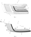
Fig. 1 shows a schematic drawing of a vehicle lamp comprising the optical assembly according to the present invention. -
Fig. 2 shows a schematic drawing of the optical assembly according to the present invention. -
Fig. 3 shows another schematic drawing of the optical assembly according to the present invention. -
Fig. 4 shows another schematic drawing of the optical assembly according to the present invention. - Embodiments of the present invention will be described demonstratively below. As those skilled in the art should realize, the embodiments described can be amended in various ways without departing from the concept of the present invention. Thus, the accompanying drawings and the Description are in essence demonstrative and non-limiting. In the following text, identical drawing reference labels generally indicate functionally identical or similar elements.
-
Fig. 1 shows avehicle lamp 1, comprising anouter lens 2, and abezel 3 and anoptical assembly 4 which are arranged behind theouter lens 2. A through-hole for theoptical assembly 4 is provided in thebezel 3; at least a light exit region of theoptical assembly 4 can pass through the through-hole, such that the region is visible from the outside when the vehicle lamp is installed in a vehicle. It must be explained that only those parts of the vehicle lamp which are important for expounding the present invention are shown here; other components are not shown, e.g. a vehicle lamp housing, wiring harness, etc. - The
optical assembly 4 in the vehicle lamp infig. 1 is shown in different drawings infigs. 2 - 4 , whereinfig. 2 shows a front view of theoptical assembly 4;figs. 3 and 4 show rear views of theoptical assembly 4. In order to show the relevant structure more clearly, one element of theoptical assembly 4 offig. 3 has been shifted, and this element has been flipped over infig. 4 . - The
optical assembly 4 comprises a firstlight guide element 6 and a secondlight guide element 5 arranged in a superposed fashion in a main exit direction H of light emitted by the optical assembly. The main exit direction can be determined according to the particular application of the optical assembly. For example, when the optical assembly is used for a vehicle lamp, e.g. a headlamp or tail lamp of a vehicle, the main exit direction corresponds to a longitudinal direction of the vehicle. Theoptical assembly 4 further comprises alight source 8 allocated to the firstlight guide element 6. - The first
light guide element 6 takes the form of an elongated light guide rod, which has a circular cross section, and the cross sectional dimensions are constant in size in a length direction. Thelight source 8 is arranged at an end of the firstlight guide element 6. Only the light source is shown here; a support for bearing the light source, e.g. a printed circuit board, and an associated heat sink, are not shown. Of course, the light source can also be arranged on the heat sink directly. The light source can be a light emitting diode, a color thereof being selected as required. Alternatively, the firstlight guide element 6 can have a gradually changing cross-sectional size in the length direction thereof. The cross section is also not limited to being circular as mentioned above. - The first
light guide element 6 has a first light in-coupling region 30 disposed at an end, a first light out-coupling surface 32 and alight deflection surface 31, wherein light that is coupled into the firstlight guide element 6 via the first light in-coupling region 30 is reflected towards the first light out-coupling surface 32 by thelight deflection surface 31, and finally exits through the first light out-coupling surface 32 towards the secondlight guide element 5. Thelight deflection surface 31 takes the form of an optical tooth array, being distributed on a predetermined length segment in a length running direction of the firstlight guide element 6, and can change a reflection direction of arriving light such that the reflected light, after arriving at the first light out-coupling surface 32, can leave the firstlight guide element 6 at this position. - The second
light guide element 5 is arranged in front of the firstlight guide element 6 in the main exit direction H. The secondlight guide element 5 has a second light in-coupling surface 10 and a second light out-coupling surface 11; the second light in-coupling surface 10 faces the first light out-coupling surface 32. The second light in-coupling surface 10 and second light out-coupling surface 11 define the thickness of the secondlight guide element 5. The secondlight guide element 5 takes the form of a light guide block, and the thickness thereof is significantly greater than the cross-sectional dimensions of the firstlight guide element 6, e.g. 30 mm or thicker. Aside surface 12 bridging together the second light in-coupling surface 10 and second light out-coupling surface 11 is a light reflection surface. When light that has entered the secondlight guide element 5 via the second light in-coupling surface 10 arrives at theside surface 12, it experiences total reflection at this position, and after being reflected, continues to propagate towards the second light out-coupling surface 11. - To achieve a richer illumination effect, a light exit structure with a predetermined pattern can be provided on the
side surface 12, such that light can exit through the light exit structure, e.g. apoint array 19 visible infigs. 1 and 2 , which takes the form of a strip array of convex or concave points. - The second
light guide element 5 also has a fixingstructure 18, in order to fix it on a support, e.g. thebezel 3. The fixingstructure 18 interacts with a cooperating fixing structure that is constructed on the support but not shown; for example, a fixed connection is established by means of engagement, threaded connection or bonding, etc. For this purpose, the fixingstructure 18 for example takes the form of an engaging tongue or has a through-hole for leading a screw through. Preferably, the fixingstructure 18 is integrally formed at a predetermined region of the secondlight guide element 5. Of course, the firstlight guide element 6 also has a corresponding fixing structure, in order to occupy the correct position relative to the light source and second light guide element. - The length running direction of the first
light guide element 6 corresponds to a length running direction of the secondlight guide element 5; thus, the first light out-coupling surface 32 and second light in-coupling surface 10 which are facing each other enable light to arrive at the second light guide element via the first light guide element as well as possible. - The length running directions of the first
light guide element 6 and secondlight guide element 5 can be designed according to a desired illumination effect. For this purpose, they can take the form of a straight line, a curved line or a combination thereof. In order to further improve the light exit effect, an additional light distribution structure can be provided on the relevant surface in at least one of the firstlight guide element 6 and secondlight guide element 5, to further increase the uniformity of exiting light. - The drawings of
figs. 3 and 4 show that light distribution structures are provided on partial segments of the first light out-coupling surface 32 and second light in-coupling surface 10, which face each other, of the firstlight guide element 6 and secondlight guide element 5. In order to better display the light distribution structures, infig. 3 , the firstlight guide element 6 has been translated downwards relative to a position, indicated by a dotted line, that should actually be occupied by the firstlight guide element 6; and infig. 4 , the firstlight guide element 6 has been flipped through 180 degrees. - In the example shown, the first
light guide element 6 and secondlight guide element 5 both have a curved segment. Specifically, the firstlight guide element 6 has afirst segment 33, asecond segment 34, and athird segment 35 arranged therebetween, wherein a main extension direction of thefirst segment 33 is different from a main extension direction of thesecond segment 34, and thethird segment 35 is a curved segment which bridges them together. The secondlight guide element 5 has afourth segment 13, afifth segment 14, and asixth segment 15 arranged therebetween, wherein main extension directions of thefourth segment 13 andfifth segment 14 are different, and thesixth segment 15 is a curved segment which bridges them together. - It can be seen from
fig. 3 that the secondlight guide element 5 is provided at the sixth segment thereof with a first light distribution structure on the second light in-coupling surface 10; the first light distribution structure takes the form of a combination of a pillow-like array 16 and afirst strip array 17. Here, a light exit surface of the smallest block-like constituent unit of the pillow-like array 16 can be a convex surface or concave surface, and a cross section of the smallest strip-like constituent unit of thestrip array 17 can be triangular, circular or another suitable form. - It can be seen from
fig. 4 that the firstlight guide element 6 is provided at thethird segment 35 thereof with a second light distribution structure on the first light out-coupling surface 32; the second light distribution structure takes the form of asecond strip array 36, and a cross section of the smallest strip-like constituent unit of the strip array can likewise be triangular, circular or another suitable form. The second light distribution structure disposed on the first light guide element faces the first light distribution structure disposed on the second light guide element. - Although particular forms of the light distribution structures disposed on the two light guide elements are shown in
figs. 3 and 4 , it must be understood that the light distribution structures can be set according to specific needs. For example, light distribution structures all taking the form of a pillow-like array or strip array can be provided on the second light guide element, or a light distribution structure taking the form of a pillow-like array can be provided on the first light guide element. If necessary, the abovementioned light distribution structure can be provided on just one of the two light guide elements, as long as uniformity of exiting light can be satisfied. - Especially when the first light out-
coupling surface 32 of thethird segment 35 of the firstlight guide element 6 and the second light in-coupling surface 10 of thesixth segment 15 of the secondlight guide element 5 are twisted surfaces, the abovementioned light distribution structures are provided on both of the light guide elements, thereby ensuring the uniformity of exiting light at the curved segments. This is because, compared to non-twisted surfaces, the propagation direction of light is more uncontrolled after passing through a twisted surface, and it is even possible that the light will not reach the light out-coupling surface as a result, thereby adversely affecting the light exit effect. Preferably, a running direction of the light distribution structure disposed on the secondlight guide element 5 is matched to a running direction of a segment adjacent to the curved segment. For example, the smallest strip-like constituent unit of thestrip array 17 can be regarded as an extension of thefifth segment 14 in an extension direction thereof, and surfaces of each row of units in the pillow-like array 16 are parallel to the light in-coupling surface of thefourth segment 13 overall. Thus, astep 18 occurs in a region provided with the light distribution structure of the curved segment of the second light guide element, as can be seen especially clearly fromfig. 4 . - It must be explained that although just one curved segment is shown in the drawings, multiple curved segments can also occur, especially twisted segments having twisted surfaces, with light distribution structures being correspondingly provided at this region.
- To further improve the uniformity of exiting light, a light homogenizing structure can be provided at the light out-coupling surface of the second light guide element, e.g. a pillow-like structure array.
- The first light guide element and second light guide element can be injection-molded from a light-transmitting material, e.g. polycarbonate, poly(methyl methacrylate), etc. This facilitates cost-effective manufacture.
- The optical assembly can be used for a vehicle lamp of a vehicle, e.g. for a daytime running lamp, brake lamp, indicator lamp, etc. The light emission color and power of the light source are chosen according to the type of vehicle lamp used.
- The present invention, instead of being limited to the above-described structure, can also have other variants. While the present invention has been described above by a limited number of embodiments, benefiting from the present invention, those of ordinary skill in the art can design other embodiments without departing from the scope of protection of the present invention. Thus, the scope of protection of the present invention should be defined by the attached claims alone.
Claims (10)
- Optical assembly (4), having a main exit direction (H), the optical assembly comprising a light source (8), and a first light guide element (6) and a second light guide element (5) which are arranged in a superposed fashion in the main exit direction, wherein the light source (8) is allocated to the first light guide element (6), and the first light guide element (6) has a first light in-coupling region (30) and a first light out-coupling surface (32), the second light guide element (5) has a second light in-coupling surface (10) and a second light out-coupling surface (11), the first light out-coupling surface (32) faces the second light in-coupling surface (10), a light distribution structure being provided on at least a partial segment of at least one of the first light out-coupling surface (32) and the second light in-coupling surface (10) characterized in that the first light guide element (6) and the second light guide element (5) have curved segments, the curved segments each being a transitional segment of one segment having a first main extension direction and another segment having a second main extension direction, the main extension directions being different, and the light distribution structure being disposed at the curved segment.
- Optical assembly (4) according to Claim 1, characterized in that the first light guide element (6) is a light guide rod, the second light guide element (5) is a light guide block, and a length running direction of the first light guide element (6) corresponds to a length running direction of the second light guide element (5).
- Optical assembly (4) according to Claim 1, characterized in that a segment adjacent to the curved segment is offset in the main exit direction (H).
- Optical assembly (4) according to Claim 1, characterized in that the second light out-coupling surface (11) is provided with a light homogenizing structure.
- Optical assembly (4) according to any one of Claims 1 - 4, characterized in that the light distribution structure is a geometric structure that is convex and/or concave from a corresponding surface.
- Optical assembly (4) according to Claim 5, characterized in that the geometric structure takes the form of a strip array, a pillow-like array or a combination thereof.
- Optical assembly (4) according to Claim 6, characterized in that the geometric structure has a triangular or arc-shaped cross section.
- Optical assembly (4) according to Claim 6, characterized in that the geometric structure is disposed on an extended surface of an adjacent segment or on a surface parallel to a surface of an adjacent segment.
- Optical assembly (4) according to any one of Claims 1 - 4, characterized in that a side surface (12) between the second light in-coupling surface (10) and second light out-coupling surface (11) of the second light guide element (5) is a reflection surface, wherein a light exit structure with a predetermined pattern is provided on the side surface (12).
- Vehicle lamp, characterized by comprising the optical assembly (4) according to any one of Claims 1 - 9.
Applications Claiming Priority (3)
| Application Number | Priority Date | Filing Date | Title |
|---|---|---|---|
| CN201910972239.8A CN112728499B (en) | 2019-10-14 | 2019-10-14 | Optics and Lighting |
| CN201921710085.7U CN210771921U (en) | 2019-10-14 | 2019-10-14 | Optical components and lights |
| PCT/EP2020/077965 WO2021073951A1 (en) | 2019-10-14 | 2020-10-06 | Optical assembly and vehicle lamp |
Publications (2)
| Publication Number | Publication Date |
|---|---|
| EP4045844A1 EP4045844A1 (en) | 2022-08-24 |
| EP4045844B1 true EP4045844B1 (en) | 2024-12-04 |
Family
ID=72752924
Family Applications (1)
| Application Number | Title | Priority Date | Filing Date |
|---|---|---|---|
| EP20786540.3A Active EP4045844B1 (en) | 2019-10-14 | 2020-10-06 | Optical assembly and vehicle lamp |
Country Status (4)
| Country | Link |
|---|---|
| US (1) | US12000555B2 (en) |
| EP (1) | EP4045844B1 (en) |
| KR (1) | KR102691221B1 (en) |
| WO (1) | WO2021073951A1 (en) |
Families Citing this family (1)
| Publication number | Priority date | Publication date | Assignee | Title |
|---|---|---|---|---|
| CA190732S (en) * | 2019-07-19 | 2022-04-21 | Bugatti Int S A | Vehicle rear light |
Family Cites Families (11)
| Publication number | Priority date | Publication date | Assignee | Title |
|---|---|---|---|---|
| AT503926B1 (en) | 2007-01-22 | 2008-02-15 | Zizala Lichtsysteme Gmbh | Lighting device for producing lighting function for lighting unit or headlight of vehicle, has two light guide rods arranged such that their normal-projections passes into level in area standing normal to main light exit direction |
| EP2440840A4 (en) * | 2009-06-12 | 2016-08-24 | Federal Mogul Corp | Distributed lighting assembly |
| FR2977926B1 (en) | 2011-06-30 | 2014-09-12 | Valeo Vision | OPTICAL DEVICE AND SYSTEM FOR SIGNALING AND / OR LIGHTING |
| ITTV20130033A1 (en) | 2013-03-01 | 2014-09-02 | Automotive Lighting Italia Spa | AUTOMOTIVE HEADLIGHT |
| AT515470A1 (en) | 2014-03-04 | 2015-09-15 | Zizala Lichtsysteme Gmbh | Light coupling protection between light functions |
| AT517019B1 (en) | 2015-04-02 | 2017-02-15 | Zkw Group Gmbh | Lighting device and motor vehicle headlights |
| KR20170020589A (en) * | 2015-08-12 | 2017-02-23 | 희성전자 주식회사 | Light guide plate having mirror pattern and display apparatus including the same |
| DE102015118511B4 (en) | 2015-10-29 | 2023-01-05 | Dr. Ing. H.C. F. Porsche Aktiengesellschaft | Light assembly for a motor vehicle |
| US10274152B2 (en) | 2017-03-27 | 2019-04-30 | Valeo North America, Inc. | Lighting apparatus and method of alignment |
| CN207262329U (en) | 2017-04-27 | 2018-04-20 | 法雷奥照明湖北技术中心有限公司 | Beam steering devices and vehicle lamp assembly |
| CN110274206B (en) | 2018-03-14 | 2023-03-24 | 株式会社小糸制作所 | Vehicle lamp |
-
2020
- 2020-10-06 KR KR1020227012300A patent/KR102691221B1/en active Active
- 2020-10-06 EP EP20786540.3A patent/EP4045844B1/en active Active
- 2020-10-06 US US17/764,592 patent/US12000555B2/en active Active
- 2020-10-06 WO PCT/EP2020/077965 patent/WO2021073951A1/en not_active Ceased
Also Published As
| Publication number | Publication date |
|---|---|
| KR20220053033A (en) | 2022-04-28 |
| US20220349543A1 (en) | 2022-11-03 |
| EP4045844A1 (en) | 2022-08-24 |
| WO2021073951A1 (en) | 2021-04-22 |
| KR102691221B1 (en) | 2024-08-05 |
| US12000555B2 (en) | 2024-06-04 |
Similar Documents
| Publication | Publication Date | Title |
|---|---|---|
| US11828432B2 (en) | Light-guiding assembly, vehicle lamp, and vehicle | |
| JP6044812B2 (en) | Lighting unit for headlamp | |
| US8434892B2 (en) | Collimator assembly | |
| KR101457232B1 (en) | Rear-loaded light emitting diode module for automotive rear combination lamps | |
| US20080232127A1 (en) | Vehicle lamp | |
| US20160193954A1 (en) | Vehicle lamp | |
| CN113639247A (en) | Light guide member, light emitting assembly, lighting device and vehicle | |
| CN109424909B (en) | Lighting and/or signalling device for a motor vehicle | |
| CN104105921A (en) | Light-emitting unit for projector lamp | |
| US9581307B2 (en) | Block light module | |
| JP2016119273A (en) | Vehicular lighting fixture | |
| CN104896396A (en) | Light coupling protection between light functions | |
| KR20160123286A (en) | Lighting and/or signalling system with light guides for a vehicle | |
| ITUB20156264A1 (en) | LIGHTING DEVICE FOR VEHICLES | |
| CN110715257B (en) | Light guide device, lighting and/or signalling device and motor vehicle | |
| US12000555B2 (en) | Optical assembly and vehicle lamp | |
| CN210771921U (en) | Optical components and lights | |
| US10627560B2 (en) | Optical system for lighting equipment, especially for a signal lamp for motor vehicles | |
| CN113330249B (en) | Lighting devices for vehicles | |
| CN109506199B (en) | Small-thickness lighting device capable of generating uniform illumination | |
| CN112728499B (en) | Optics and Lighting | |
| CN110836355B (en) | Lighting system for a vehicle | |
| US10648637B1 (en) | Optical device for a lighting and/or signalling device of an automobile vehicle | |
| US9340151B2 (en) | Optical coupler for vehicle lighting systems | |
| US20240426455A1 (en) | Lighting device for a motor vehicle |
Legal Events
| Date | Code | Title | Description |
|---|---|---|---|
| STAA | Information on the status of an ep patent application or granted ep patent |
Free format text: STATUS: UNKNOWN |
|
| STAA | Information on the status of an ep patent application or granted ep patent |
Free format text: STATUS: THE INTERNATIONAL PUBLICATION HAS BEEN MADE |
|
| PUAI | Public reference made under article 153(3) epc to a published international application that has entered the european phase |
Free format text: ORIGINAL CODE: 0009012 |
|
| STAA | Information on the status of an ep patent application or granted ep patent |
Free format text: STATUS: REQUEST FOR EXAMINATION WAS MADE |
|
| 17P | Request for examination filed |
Effective date: 20220408 |
|
| AK | Designated contracting states |
Kind code of ref document: A1 Designated state(s): AL AT BE BG CH CY CZ DE DK EE ES FI FR GB GR HR HU IE IS IT LI LT LU LV MC MK MT NL NO PL PT RO RS SE SI SK SM TR |
|
| DAV | Request for validation of the european patent (deleted) | ||
| DAX | Request for extension of the european patent (deleted) | ||
| P01 | Opt-out of the competence of the unified patent court (upc) registered |
Effective date: 20230528 |
|
| GRAP | Despatch of communication of intention to grant a patent |
Free format text: ORIGINAL CODE: EPIDOSNIGR1 |
|
| STAA | Information on the status of an ep patent application or granted ep patent |
Free format text: STATUS: GRANT OF PATENT IS INTENDED |
|
| RIC1 | Information provided on ipc code assigned before grant |
Ipc: G02B 6/04 20060101ALI20240722BHEP Ipc: F21V 8/00 20060101ALI20240722BHEP Ipc: F21S 43/27 20180101ALI20240722BHEP Ipc: F21S 43/247 20180101ALI20240722BHEP Ipc: F21S 43/245 20180101ALI20240722BHEP Ipc: F21S 43/237 20180101AFI20240722BHEP |
|
| INTG | Intention to grant announced |
Effective date: 20240809 |
|
| GRAS | Grant fee paid |
Free format text: ORIGINAL CODE: EPIDOSNIGR3 |
|
| GRAA | (expected) grant |
Free format text: ORIGINAL CODE: 0009210 |
|
| STAA | Information on the status of an ep patent application or granted ep patent |
Free format text: STATUS: THE PATENT HAS BEEN GRANTED |
|
| AK | Designated contracting states |
Kind code of ref document: B1 Designated state(s): AL AT BE BG CH CY CZ DE DK EE ES FI FR GB GR HR HU IE IS IT LI LT LU LV MC MK MT NL NO PL PT RO RS SE SI SK SM TR |
|
| REG | Reference to a national code |
Ref country code: CH Ref legal event code: EP |
|
| REG | Reference to a national code |
Ref country code: DE Ref legal event code: R096 Ref document number: 602020042582 Country of ref document: DE |
|
| REG | Reference to a national code |
Ref country code: IE Ref legal event code: FG4D |
|
| REG | Reference to a national code |
Ref country code: LT Ref legal event code: MG9D |
|
| REG | Reference to a national code |
Ref country code: NL Ref legal event code: MP Effective date: 20241204 |
|
| PG25 | Lapsed in a contracting state [announced via postgrant information from national office to epo] |
Ref country code: HR Free format text: LAPSE BECAUSE OF FAILURE TO SUBMIT A TRANSLATION OF THE DESCRIPTION OR TO PAY THE FEE WITHIN THE PRESCRIBED TIME-LIMIT Effective date: 20241204 |
|
| PG25 | Lapsed in a contracting state [announced via postgrant information from national office to epo] |
Ref country code: FI Free format text: LAPSE BECAUSE OF FAILURE TO SUBMIT A TRANSLATION OF THE DESCRIPTION OR TO PAY THE FEE WITHIN THE PRESCRIBED TIME-LIMIT Effective date: 20241204 |
|
| PG25 | Lapsed in a contracting state [announced via postgrant information from national office to epo] |
Ref country code: BG Free format text: LAPSE BECAUSE OF FAILURE TO SUBMIT A TRANSLATION OF THE DESCRIPTION OR TO PAY THE FEE WITHIN THE PRESCRIBED TIME-LIMIT Effective date: 20241204 |
|
| PG25 | Lapsed in a contracting state [announced via postgrant information from national office to epo] |
Ref country code: ES Free format text: LAPSE BECAUSE OF FAILURE TO SUBMIT A TRANSLATION OF THE DESCRIPTION OR TO PAY THE FEE WITHIN THE PRESCRIBED TIME-LIMIT Effective date: 20241204 |
|
| PG25 | Lapsed in a contracting state [announced via postgrant information from national office to epo] |
Ref country code: NO Free format text: LAPSE BECAUSE OF FAILURE TO SUBMIT A TRANSLATION OF THE DESCRIPTION OR TO PAY THE FEE WITHIN THE PRESCRIBED TIME-LIMIT Effective date: 20250304 |
|
| PG25 | Lapsed in a contracting state [announced via postgrant information from national office to epo] |
Ref country code: GR Free format text: LAPSE BECAUSE OF FAILURE TO SUBMIT A TRANSLATION OF THE DESCRIPTION OR TO PAY THE FEE WITHIN THE PRESCRIBED TIME-LIMIT Effective date: 20250305 Ref country code: LV Free format text: LAPSE BECAUSE OF FAILURE TO SUBMIT A TRANSLATION OF THE DESCRIPTION OR TO PAY THE FEE WITHIN THE PRESCRIBED TIME-LIMIT Effective date: 20241204 |
|
| PG25 | Lapsed in a contracting state [announced via postgrant information from national office to epo] |
Ref country code: RS Free format text: LAPSE BECAUSE OF FAILURE TO SUBMIT A TRANSLATION OF THE DESCRIPTION OR TO PAY THE FEE WITHIN THE PRESCRIBED TIME-LIMIT Effective date: 20250304 |
|
| PG25 | Lapsed in a contracting state [announced via postgrant information from national office to epo] |
Ref country code: NL Free format text: LAPSE BECAUSE OF FAILURE TO SUBMIT A TRANSLATION OF THE DESCRIPTION OR TO PAY THE FEE WITHIN THE PRESCRIBED TIME-LIMIT Effective date: 20241204 |
|
| REG | Reference to a national code |
Ref country code: AT Ref legal event code: MK05 Ref document number: 1748527 Country of ref document: AT Kind code of ref document: T Effective date: 20241204 |
|
| PG25 | Lapsed in a contracting state [announced via postgrant information from national office to epo] |
Ref country code: SM Free format text: LAPSE BECAUSE OF FAILURE TO SUBMIT A TRANSLATION OF THE DESCRIPTION OR TO PAY THE FEE WITHIN THE PRESCRIBED TIME-LIMIT Effective date: 20241204 |
|
| PG25 | Lapsed in a contracting state [announced via postgrant information from national office to epo] |
Ref country code: PL Free format text: LAPSE BECAUSE OF FAILURE TO SUBMIT A TRANSLATION OF THE DESCRIPTION OR TO PAY THE FEE WITHIN THE PRESCRIBED TIME-LIMIT Effective date: 20241204 |
|
| PG25 | Lapsed in a contracting state [announced via postgrant information from national office to epo] |
Ref country code: IS Free format text: LAPSE BECAUSE OF FAILURE TO SUBMIT A TRANSLATION OF THE DESCRIPTION OR TO PAY THE FEE WITHIN THE PRESCRIBED TIME-LIMIT Effective date: 20250404 |
|
| PG25 | Lapsed in a contracting state [announced via postgrant information from national office to epo] |
Ref country code: PT Free format text: LAPSE BECAUSE OF FAILURE TO SUBMIT A TRANSLATION OF THE DESCRIPTION OR TO PAY THE FEE WITHIN THE PRESCRIBED TIME-LIMIT Effective date: 20250404 |
|
| PG25 | Lapsed in a contracting state [announced via postgrant information from national office to epo] |
Ref country code: EE Free format text: LAPSE BECAUSE OF FAILURE TO SUBMIT A TRANSLATION OF THE DESCRIPTION OR TO PAY THE FEE WITHIN THE PRESCRIBED TIME-LIMIT Effective date: 20241204 |
|
| PG25 | Lapsed in a contracting state [announced via postgrant information from national office to epo] |
Ref country code: RO Free format text: LAPSE BECAUSE OF FAILURE TO SUBMIT A TRANSLATION OF THE DESCRIPTION OR TO PAY THE FEE WITHIN THE PRESCRIBED TIME-LIMIT Effective date: 20241204 Ref country code: AT Free format text: LAPSE BECAUSE OF FAILURE TO SUBMIT A TRANSLATION OF THE DESCRIPTION OR TO PAY THE FEE WITHIN THE PRESCRIBED TIME-LIMIT Effective date: 20241204 |
|
| PG25 | Lapsed in a contracting state [announced via postgrant information from national office to epo] |
Ref country code: SK Free format text: LAPSE BECAUSE OF FAILURE TO SUBMIT A TRANSLATION OF THE DESCRIPTION OR TO PAY THE FEE WITHIN THE PRESCRIBED TIME-LIMIT Effective date: 20241204 |
|
| PG25 | Lapsed in a contracting state [announced via postgrant information from national office to epo] |
Ref country code: CZ Free format text: LAPSE BECAUSE OF FAILURE TO SUBMIT A TRANSLATION OF THE DESCRIPTION OR TO PAY THE FEE WITHIN THE PRESCRIBED TIME-LIMIT Effective date: 20241204 |
|
| PG25 | Lapsed in a contracting state [announced via postgrant information from national office to epo] |
Ref country code: IT Free format text: LAPSE BECAUSE OF FAILURE TO SUBMIT A TRANSLATION OF THE DESCRIPTION OR TO PAY THE FEE WITHIN THE PRESCRIBED TIME-LIMIT Effective date: 20241204 |
|
| REG | Reference to a national code |
Ref country code: DE Ref legal event code: R097 Ref document number: 602020042582 Country of ref document: DE |
|
| PG25 | Lapsed in a contracting state [announced via postgrant information from national office to epo] |
Ref country code: SE Free format text: LAPSE BECAUSE OF FAILURE TO SUBMIT A TRANSLATION OF THE DESCRIPTION OR TO PAY THE FEE WITHIN THE PRESCRIBED TIME-LIMIT Effective date: 20241204 |
|
| PG25 | Lapsed in a contracting state [announced via postgrant information from national office to epo] |
Ref country code: DK Free format text: LAPSE BECAUSE OF FAILURE TO SUBMIT A TRANSLATION OF THE DESCRIPTION OR TO PAY THE FEE WITHIN THE PRESCRIBED TIME-LIMIT Effective date: 20241204 |
|
| PLBE | No opposition filed within time limit |
Free format text: ORIGINAL CODE: 0009261 |
|
| STAA | Information on the status of an ep patent application or granted ep patent |
Free format text: STATUS: NO OPPOSITION FILED WITHIN TIME LIMIT |
|
| 26N | No opposition filed |
Effective date: 20250905 |
|
| PGFP | Annual fee paid to national office [announced via postgrant information from national office to epo] |
Ref country code: DE Payment date: 20251015 Year of fee payment: 6 |
|
| PGFP | Annual fee paid to national office [announced via postgrant information from national office to epo] |
Ref country code: FR Payment date: 20251027 Year of fee payment: 6 |