EP4045802B1 - Methods for forming a composite tube assembly and composite tube assembly comprising slotted joints - Google Patents
Methods for forming a composite tube assembly and composite tube assembly comprising slotted joints Download PDFInfo
- Publication number
- EP4045802B1 EP4045802B1 EP20800503.3A EP20800503A EP4045802B1 EP 4045802 B1 EP4045802 B1 EP 4045802B1 EP 20800503 A EP20800503 A EP 20800503A EP 4045802 B1 EP4045802 B1 EP 4045802B1
- Authority
- EP
- European Patent Office
- Prior art keywords
- fitting
- tube
- diameter
- slot
- tapered outer
- Prior art date
- Legal status (The legal status is an assumption and is not a legal conclusion. Google has not performed a legal analysis and makes no representation as to the accuracy of the status listed.)
- Active
Links
Images



Classifications
-
- F—MECHANICAL ENGINEERING; LIGHTING; HEATING; WEAPONS; BLASTING
- F16—ENGINEERING ELEMENTS AND UNITS; GENERAL MEASURES FOR PRODUCING AND MAINTAINING EFFECTIVE FUNCTIONING OF MACHINES OR INSTALLATIONS; THERMAL INSULATION IN GENERAL
- F16C—SHAFTS; FLEXIBLE SHAFTS; ELEMENTS OR CRANKSHAFT MECHANISMS; ROTARY BODIES OTHER THAN GEARING ELEMENTS; BEARINGS
- F16C7/00—Connecting-rods or like links pivoted at both ends; Construction of connecting-rod heads
- F16C7/02—Constructions of connecting-rods with constant length
- F16C7/026—Constructions of connecting-rods with constant length made of fibre reinforced resin
-
- F—MECHANICAL ENGINEERING; LIGHTING; HEATING; WEAPONS; BLASTING
- F16—ENGINEERING ELEMENTS AND UNITS; GENERAL MEASURES FOR PRODUCING AND MAINTAINING EFFECTIVE FUNCTIONING OF MACHINES OR INSTALLATIONS; THERMAL INSULATION IN GENERAL
- F16L—PIPES; JOINTS OR FITTINGS FOR PIPES; SUPPORTS FOR PIPES, CABLES OR PROTECTIVE TUBING; MEANS FOR THERMAL INSULATION IN GENERAL
- F16L21/00—Joints with sleeve or socket
- F16L21/007—Joints with sleeve or socket clamped by a wedging action
-
- B—PERFORMING OPERATIONS; TRANSPORTING
- B29—WORKING OF PLASTICS; WORKING OF SUBSTANCES IN A PLASTIC STATE IN GENERAL
- B29C—SHAPING OR JOINING OF PLASTICS; SHAPING OF MATERIAL IN A PLASTIC STATE, NOT OTHERWISE PROVIDED FOR; AFTER-TREATMENT OF THE SHAPED PRODUCTS, e.g. REPAIRING
- B29C65/00—Joining or sealing of preformed parts, e.g. welding of plastics materials; Apparatus therefor
- B29C65/48—Joining or sealing of preformed parts, e.g. welding of plastics materials; Apparatus therefor using adhesives, i.e. using supplementary joining material; solvent bonding
-
- B—PERFORMING OPERATIONS; TRANSPORTING
- B29—WORKING OF PLASTICS; WORKING OF SUBSTANCES IN A PLASTIC STATE IN GENERAL
- B29C—SHAPING OR JOINING OF PLASTICS; SHAPING OF MATERIAL IN A PLASTIC STATE, NOT OTHERWISE PROVIDED FOR; AFTER-TREATMENT OF THE SHAPED PRODUCTS, e.g. REPAIRING
- B29C65/00—Joining or sealing of preformed parts, e.g. welding of plastics materials; Apparatus therefor
- B29C65/56—Joining or sealing of preformed parts, e.g. welding of plastics materials; Apparatus therefor using mechanical means or mechanical connections, e.g. form-fits
Definitions
- the present disclosure relates generally to composite tube assemblies and more particularly to composite tube assemblies having form locking fittings.
- Composite materials offer high stiffness and/or strength-to-weight ratios.
- Composite tube assemblies are formed from composite materials and are used for transferring loads in structures such as aircraft or spacecraft. Other applications include control rods, containers, ducts, panel inserts, torque tubes, etc.
- composite tube assemblies In vehicles such as aircraft, it is beneficial to use composite tube assemblies rather than assemblies primarily composed of metal. They are lighter and stronger than comparable metal tube assemblies.
- the composite tube assemblies typically incorporate carbon fiber (“CF”) tubes and are lighter in weight, more resistant to corrosion, stronger and more inert relative to substantially metallic tube assemblies.
- CFRP carbon fiber
- Composite tube assemblies may be used in an overhead luggage bin (or stow bin) assemblies in an aircraft to provide structural support both when the bin is in an open configuration and when it is closed.
- the composite tube assemblies may also be used as structural members in vehicle frames.
- a fitting or insert such as a Hylock insert
- the composite tube end is compressed over a smaller diameter of the fitting to form the composite tube assembly.
- This bunching up of the composite tube end can result in cracked CF material after forming.
- the compressed and bunched composite tube end then requires post processing to clean up the formed area, which adds complexity and risk to the manufacturing process.
- Other forming issues are seen with tubes formed from composite materials having higher cure temperature resins, as it is more difficult to achieve the glass transition temperature (Tg) range of such composite materials and thus, it is more difficult to compress such tube ends over the fitting.
- Tg glass transition temperature
- Composite tube assemblies 10 including fittings 12 are described in U.S. Patent No. 8,205,315 .
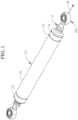
- an end 14 of a composite tube or tube 16 is fitted over a fitting 12 as shown in FIG. 1 .
- the composite tube 16 may be produced by winding composite fibers in a form of a filament (and/or a tape) having an epoxy resin over a tubular mandrel. Any of a number of suitable machines known to those skilled in the art can be used for this purpose.
- the composite tube may be a fiber reinforced composite formed with a thermoset or a thermoplastic resin.
- the composite tube may be a liquid molded tube that may include fiber reinforcement.
- the composite fibers may be wound along a direction that is substantially helical with respect to a longitudinal axis 18 of the composite tube. In other words, in a direction along the circumference transverse or perpendicular to the longitudinal axis of the tube. In one embodiment, the composite fibers are also wound at a very small helical angle (or angles) with respect to the longitudinal axis.
- embodiments of the composite tube 16 are not limited thereto. That is, the composite tube 16 may be produced by winding filaments and/or pre-impregnated composite tapes in any known manner and at any angle.
- the composite tube may include fibers oriented in multiple directions, as for example in the hoop direction (90° to the longitudinal axis) as well as fibers along the longitudinal axis as well as other angles relative to the longitudinal axis, as for example along 45°.
- the fitting 12 includes a tapered outer surface 20, as for example shown in FIGS. 2 ad 3, tapering from a larger diameter section 19 to smaller diameter section 21 distally relative to the tube 16 defining reduced diameter or tapered portion 23.
- the tapered outer surface 20 may have a smooth outer surface as for example shown in FIG. 3 or may have a textured outer surface, as for example shown in FIG. 2 , for better adhesion.
- the textured outer surface may be formed by a plurality of adjacent annular grooves.
- the outer surface may have multiple tapering outer surfaces, as for example shown in FIG. 6A .
- a first cylindrical outer surface 42 may axially taper at a first angle 44.
- a second cylindrical outer surface 46 extending axially from the first cylindrical outer surface, may taper axially at a second angle 48 greater than the first angle 44 such that it tapers to a smaller diameter in a direction away from the first cylindrical outer surface.
- Fittings also typically include a cylindrical flange 22 proximate the smaller diameter of the tapering outer surfaces.
- a neck 24 extends axially from the flange in a direction away from the tapering outer surface.
- An end fitting, such a clevis bolt 26, may be received in the neck and connect to the fitting, as for example shown in FIG. 1 .
- a tube end portion 27, to be fitted over (i.e., mated with) the tapered outer surface 20 of the fitting is slotted with a slot 32, in at least one location but, preferably in at least at two different locations to form at least two cantilevered arm sections or arms 30 as for example shown in FIG. 4A .
- a slot 32 extends to the distal end 31 of the tube so as to form the cantilevered arms 30.
- more than two slots are formed as for example three, four, five, six, seven, eight, nine, ten, or more than ten to form multiple arms 30. These arms are bent and molded over the tapered surface of the fitting for coupling the tube to the fitting, as for example shown in FIG. 4B which depicts the end portion of the tube fitted over the tapered outer surface of the fitting without showing the fitting.
- a tapered portion 25 of the composite tube 10 is formed by heating the end portion 27 arms 30 of the composite tube 16, into which the fitting 12 was inserted, to a temperature sufficient for the composite tube end portion arms to become thermoplastic or moldable, as for example by softening the resin forming the composite tube.
- the tube is heated to a temperature within the glass transition temperature (T g ) range of the composite material forming the composite tube.
- T g glass transition temperature
- a heated die or any other suitable instrument may be used for this purpose.
- the end portion 27 arms 30 of the composite tube 16 are deformed to collectively have a shape and dimension substantially conforming to a shape and dimension, respectively, of the tapered portion 23 of the fitting 12.
- the tapered portion 25 of the composite tube 16 is thereby formed. As the tapered portion 25 of the composite tube 16 cools, it compresses radially on to the tapered portion 23 of the fitting 12. The tapered portion 25 of the composite tube 16 is thereby secured to the tapered portion 23 of the fitting 12 to form a mechanical lock.
- the tapered portion 25 of the composite tube 16 may also bond to the tapered portion of the fitting 12 as the softened resin cools and bonds onto the tapered portion of the fitting.
- An adhesive may also be used to help adhere the composite tube reduced diameter portion 25 to the fitting tapered portion 23. If an adhesive is used between the composite tube and the fitting, the adhesive by itself or in combination with the resin creates a bond between the composite tube and the fitting.
- the arms 30 provide flexibility (i.e., they are more flexible then the composite tube end portion when not slotted), heat, although desirable, is not necessary for bending each arm and attaching and coupling it to the tapered outer surface of the fitting. Heat is, however, desirable for accelerating the cure of the structure adhesive used on the composite tube and thus the arms.
- the heating temperature can range anywhere from ambient temperate to the upper end of the composite tube material T g range.
- a collar 70 is installed over the arms to provide appropriate force on the arms against the tube to provide a forming force in the tube without having to heat the arms ( FIGS. 1 , 7A and 7B ).
- Another benefit provided by lower temperature forming is the ability to maintain tolerances caused coefficient of the thermal expansion differences in the materials used for the tube and the fitting.
- Another benefit is the ability to use tooling made for materials that would otherwise degrade at the higher forming temperatures. Being able to use lower temperature forming, further provides a great benefit, in that it allows composite tubes made from materials with higher T g to be used as the higher temperatures required when using traditional forming methods with many materials are not necessary.
- the slotted ends of the tube may be formed in the prepreg material prior to rolling to form the tube or may be forming to the other tube after the tube is formed.
- each slot has a length 72 such that when the arms are mounted to the tapered outer surface of the fitting, each slot extends along the entirety, or substantially the entirety, of the length 74 of the fitting annular tapered outer surface 20. In other example embodiments, the length of each slot may be less than the entire length of the tapered outer surface 20.
- each slot is rectangular shaped in that each slot includes generally parallel, or parallel, opposite edges 50 extending along the entire length, or substantially the entire length, of each slot, as for example shown in FIG. 4A .
- the arms 30 shown in FIG. 4A define a shape as shown in FIG. 4B .
- FIG. 4B In another example embodiment as shown in FIG.
- each slot 32 is triangularly shaped, such that the vertex 52 of the triangle is proximal and the base 54 of the triangle is distal of the tube 16 defining the maximum spacing of the slot, or the maximum width of the slot, at the distal end 56 of the tube such that the largest width of the slot is closest to the smallest diameter section 21 of the tapered surface 20 of the fitting when the fitting if fitted in the tube end.
- the slots may have nonlinear or varying widths to accommodate different geometries of tapering of the surface of the fitting, as for example shown in FIG. 6A .
- the tube end (or hoop area) portion includes constant width slots as for example shown in FIG. 4A .
- the width of each slot is based on the reduced circumference at the distal end of the tube when the tube is mated to the fitting end and the number of slots used.
- the proximal ends of the slots may incorporate a radius at each corner to reduce stress concentrations.
- each slot width is defined by the difference of the circumference along the fitting taper divided by the number of slots.
- the length of the slot may vary based on material properties and design requirements, though in most cases the proximal end of the slot will be close to, or at, the point at which the proximal end of the taper on the fitting is located.
- the open volume left after forming between the opposite edges 60 of each slot may be filled with a filler material such as structural adhesive, or left open.
- each slot is approximately an isosceles triangle with the base defined as the slot max width (W) at the distal end 56 of the tube and the angle bisector from the vertex 52 (i.e. the "V") of the triangle to the base 54 defined as the slot length (L).
- W slot max width
- V vertex 52
- L slot length
- the width Wx at a distance X of each slot can be within 25% of Wx derived by Formula 2. In another example embodiment can be within 20% of Wx derived by Formula 2. In yet another example embodiment it can be within 15% of Wx derived by Formula 2. In another example embodiment, it can be within 10% of Wx derived by Formula 2. In a further example embodiment it can within 5% of Wx derived by Formula 2.
- the end portion area has non-linearly varying width slots as for example shown in FIG. 6A .
- the slots are shaped such that when formed over a varying angle tapered outer surface of a fitting, the two sides of the slot nearly meet or abut each other along the entire length of the slot.
- the open volume left after forming may be filled with a filler material such as structural adhesive, or left open.
- the slots are shaped based on the radial projection of the varying taper angle of the tapered outer surface of the fitting, which may result in a polygonal or curved slot shape.
- a first step 78a is provided by reducing the outer diameter of the fitting.
- one or more of the tasks described above may be absent and/or additional tasks may be performed.
- a component when referred to as being “on” another component, it can be directly on the other component or components may also be present there between.
- a component when referred to as being “coupled” to another component, it can be directly attached to the other component or intervening components may be present there between.
Landscapes
- Engineering & Computer Science (AREA)
- Mechanical Engineering (AREA)
- General Engineering & Computer Science (AREA)
- Mutual Connection Of Rods And Tubes (AREA)
- Rigid Pipes And Flexible Pipes (AREA)
Description
- The present disclosure relates generally to composite tube assemblies and more particularly to composite tube assemblies having form locking fittings.
- Composite materials offer high stiffness and/or strength-to-weight ratios. Composite tube assemblies are formed from composite materials and are used for transferring loads in structures such as aircraft or spacecraft. Other applications include control rods, containers, ducts, panel inserts, torque tubes, etc.
- In vehicles such as aircraft, it is beneficial to use composite tube assemblies rather than assemblies primarily composed of metal. They are lighter and stronger than comparable metal tube assemblies. The composite tube assemblies typically incorporate carbon fiber ("CF") tubes and are lighter in weight, more resistant to corrosion, stronger and more inert relative to substantially metallic tube assemblies. Composite tube assemblies may be used in an overhead luggage bin (or stow bin) assemblies in an aircraft to provide structural support both when the bin is in an open configuration and when it is closed. The composite tube assemblies may also be used as structural members in vehicle frames.
- To form the end of a CF tube around a fitting or insert (individually and collectively referred to herein for convenience as "fitting"), such as a Hylock insert, the composite tube end is compressed over a smaller diameter of the fitting to form the composite tube assembly. When doing so, areas of the compressed end of the composite tube bunch up and need to be accommodated or removed. This bunching up of the composite tube end can result in cracked CF material after forming. The compressed and bunched composite tube end then requires post processing to clean up the formed area, which adds complexity and risk to the manufacturing process. Other forming issues are seen with tubes formed from composite materials having higher cure temperature resins, as it is more difficult to achieve the glass transition temperature (Tg) range of such composite materials and thus, it is more difficult to compress such tube ends over the fitting.
-
- The invention is defined in the appended claims.
-
-
FIG. 1 is a perspective view of an example embodiment composite tube assembly. -
FIG. 2 is a side view of an example embodiment fitting that may be incorporated in the composite tube assembly shown inFIG. 1 . -
FIG. 3 is a side view of another example embodiment fitting that may be incorporated in the composite tube assembly shown inFIG. 1 . -
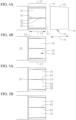
FIG. 4A is a schematically depicted side exploded view of an example embodiment slotted tube end portion and partially depicted fitting. -
FIG. 4B is a schematically depicted side view of the tube end portion shown inFIG. 4A when mated to a tapered outer surface of a fitting such as the partially shown fitting depicted inFIG. 4A . -
FIG. 5A is a schematically depicted side view of another example embodiment slotted tube end portion. -
FIG. 5B is a schematically depicted side view of the tube end portion shown inFIG. 5A when mated to a tapered outer surface of a fitting. -
FIG. 6A is a schematically depicted side exploded view of an example embodiment slotted tube end portion and partially depicted fitting having two sequentially tapered sections. -
FIG. 6B is a schematically depicted side view of the tube end portion shown inFIG. 6A when mated to a tapered outer surface of a fitting. -
FIG. 7A is a partial cross-sectional view of an example embodiment tube assembly. -
FIG. 7B is a partial cross-sectional view of another example embodiment tube assembly. -
Composite tube assemblies 10 includingfittings 12 are described inU.S. Patent No. 8,205,315 . In an example embodiment, anend 14 of a composite tube ortube 16 is fitted over afitting 12 as shown inFIG. 1 . Thecomposite tube 16 may be produced by winding composite fibers in a form of a filament (and/or a tape) having an epoxy resin over a tubular mandrel. Any of a number of suitable machines known to those skilled in the art can be used for this purpose. The composite tube may be a fiber reinforced composite formed with a thermoset or a thermoplastic resin. In other example embodiments, the composite tube may be a liquid molded tube that may include fiber reinforcement. The composite fibers may be wound along a direction that is substantially helical with respect to alongitudinal axis 18 of the composite tube. In other words, in a direction along the circumference transverse or perpendicular to the longitudinal axis of the tube. In one embodiment, the composite fibers are also wound at a very small helical angle (or angles) with respect to the longitudinal axis. However, embodiments of thecomposite tube 16 are not limited thereto. That is, thecomposite tube 16 may be produced by winding filaments and/or pre-impregnated composite tapes in any known manner and at any angle. The composite tube may include fibers oriented in multiple directions, as for example in the hoop direction (90° to the longitudinal axis) as well as fibers along the longitudinal axis as well as other angles relative to the longitudinal axis, as for example along 45°. - The
fitting 12 includes a taperedouter surface 20, as for example shown inFIGS. 2 ad 3, tapering from alarger diameter section 19 tosmaller diameter section 21 distally relative to thetube 16 defining reduced diameter or taperedportion 23. The taperedouter surface 20 may have a smooth outer surface as for example shown inFIG. 3 or may have a textured outer surface, as for example shown inFIG. 2 , for better adhesion. In an example embodiment, the textured outer surface may be formed by a plurality of adjacent annular grooves. In other example embodiments, the outer surface may have multiple tapering outer surfaces, as for example shown inFIG. 6A . For example, a first cylindricalouter surface 42 may axially taper at afirst angle 44. A second cylindricalouter surface 46, extending axially from the first cylindrical outer surface, may taper axially at asecond angle 48 greater than thefirst angle 44 such that it tapers to a smaller diameter in a direction away from the first cylindrical outer surface. Fittings also typically include acylindrical flange 22 proximate the smaller diameter of the tapering outer surfaces. Aneck 24 extends axially from the flange in a direction away from the tapering outer surface. An end fitting, such aclevis bolt 26, may be received in the neck and connect to the fitting, as for example shown inFIG. 1 . - In an example embodiment, a
tube end portion 27, to be fitted over (i.e., mated with) the taperedouter surface 20 of the fitting, is slotted with aslot 32, in at least one location but, preferably in at least at two different locations to form at least two cantilevered arm sections orarms 30 as for example shown inFIG. 4A . For illustrative purposes, only the taperedportion 23 of the fitting is schematically depicted next to thetube end portion 27 inFIG. 4A . Eachslot 32 extends to thedistal end 31 of the tube so as to form the cantileveredarms 30. In an example embodiment, more than two slots are formed as for example three, four, five, six, seven, eight, nine, ten, or more than ten to formmultiple arms 30. These arms are bent and molded over the tapered surface of the fitting for coupling the tube to the fitting, as for example shown inFIG. 4B which depicts the end portion of the tube fitted over the tapered outer surface of the fitting without showing the fitting. - A tapered
portion 25 of thecomposite tube 10 is formed by heating theend portion 27arms 30 of thecomposite tube 16, into which the fitting 12 was inserted, to a temperature sufficient for the composite tube end portion arms to become thermoplastic or moldable, as for example by softening the resin forming the composite tube. In one example embodiment, the tube is heated to a temperature within the glass transition temperature (Tg) range of the composite material forming the composite tube. A heated die or any other suitable instrument may be used for this purpose. Once theend portion 27arms 30 of thecomposite tube 16 are in a moldable state, they are then pressed and deformed to engage the taperedportion 23 of the fitting 12. That is, theend portion 27arms 30 of thecomposite tube 16 are deformed to collectively have a shape and dimension substantially conforming to a shape and dimension, respectively, of the taperedportion 23 of the fitting 12. The taperedportion 25 of thecomposite tube 16 is thereby formed. As the taperedportion 25 of thecomposite tube 16 cools, it compresses radially on to the taperedportion 23 of the fitting 12. The taperedportion 25 of thecomposite tube 16 is thereby secured to the taperedportion 23 of the fitting 12 to form a mechanical lock. The taperedportion 25 of thecomposite tube 16 may also bond to the tapered portion of the fitting 12 as the softened resin cools and bonds onto the tapered portion of the fitting. An adhesive may also be used to help adhere the composite tube reduceddiameter portion 25 to the fitting taperedportion 23. If an adhesive is used between the composite tube and the fitting, the adhesive by itself or in combination with the resin creates a bond between the composite tube and the fitting. - Applicants discovered multiple benefits by slotting (i.e. forming slots 32) or slitting the tube end portion when forming a composite tube assembly. Because the
arms 30 provide flexibility (i.e., they are more flexible then the composite tube end portion when not slotted), heat, although desirable, is not necessary for bending each arm and attaching and coupling it to the tapered outer surface of the fitting. Heat is, however, desirable for accelerating the cure of the structure adhesive used on the composite tube and thus the arms. The heating temperature can range anywhere from ambient temperate to the upper end of the composite tube material Tg range. Since the slotted tube end portion configuration defining multiple arms also allows for ambient temperature forming or bending of the arms onto the taperedouter surface 20 of the fitting, acollar 70 is installed over the arms to provide appropriate force on the arms against the tube to provide a forming force in the tube without having to heat the arms (FIGS. 1 ,7A and 7B ). Another benefit provided by lower temperature forming is the ability to maintain tolerances caused coefficient of the thermal expansion differences in the materials used for the tube and the fitting. Another benefit is the ability to use tooling made for materials that would otherwise degrade at the higher forming temperatures. Being able to use lower temperature forming, further provides a great benefit, in that it allows composite tubes made from materials with higher Tg to be used as the higher temperatures required when using traditional forming methods with many materials are not necessary. - Since the hoop structure is cut to form the slots and arms, composite materials may be used to form the composite tube that typically do not form very well. This include standard, or intermediate, or high or ultra-modE fibers and resins systems with high Tg, even with Tg significantly over 350° F. These include thermoplastic or thermoset matrix materials.
- In the prior art embodiments, where slots were not formed, the bunching up of the material after the end of the tube was compressed over the tapered surface, and required machining away of the excess material. Material then had added to the outer diameter of the tube. Such machining and addition of material is not required by slotting and forming arms on the composite tube end portion.
- In an example embodiment, the slotted ends of the tube may be formed in the prepreg material prior to rolling to form the tube or may be forming to the other tube after the tube is formed.
- In an example embodiment, each slot has a
length 72 such that when the arms are mounted to the tapered outer surface of the fitting, each slot extends along the entirety, or substantially the entirety, of thelength 74 of the fitting annular taperedouter surface 20. In other example embodiments, the length of each slot may be less than the entire length of the taperedouter surface 20. - In one example embodiment, each slot is rectangular shaped in that each slot includes generally parallel, or parallel,
opposite edges 50 extending along the entire length, or substantially the entire length, of each slot, as for example shown inFIG. 4A . When fitted and mated with the tapered outer surface of the fitting, thearms 30 shown inFIG. 4A define a shape as shown inFIG. 4B . In another example embodiment as shown inFIG. 5A , eachslot 32 is triangularly shaped, such that thevertex 52 of the triangle is proximal and thebase 54 of the triangle is distal of thetube 16 defining the maximum spacing of the slot, or the maximum width of the slot, at thedistal end 56 of the tube such that the largest width of the slot is closest to thesmallest diameter section 21 of the taperedsurface 20 of the fitting when the fitting if fitted in the tube end. In other example embodiments, the slots may have nonlinear or varying widths to accommodate different geometries of tapering of the surface of the fitting, as for example shown inFIG. 6A . For example, the slots may have varying widths such that the slot width varies along two different angles so that thearms 30 formed can mate with a fitting that has a first taperedsurface 42 tapering at afirst angle 44 and a second taperedsurface 46 extending axially from for the first tapered surface and extending at asecond angle 48 that is greater than the first angle, as for example shown inFIG. 6A . In an example embodiment, the edges of each slot are curving or continuously curving. In example embodiments, theopposite edges 60 of the slots are such that when the arms are mated over the fitting outer tapered surface, suchopposite edges 60 are parallel or almost parallel to each other and are close to each other or abut each other, as for example shown inFIGS. 5B and6B . This configuration is expected to provide better results. - Three example embodiments are provided herewith.
- The tube end (or hoop area) portion includes constant width slots as for example shown in
FIG. 4A . The width of each slot is based on the reduced circumference at the distal end of the tube when the tube is mated to the fitting end and the number of slots used. The proximal ends of the slots may incorporate a radius at each corner to reduce stress concentrations. - In this example embodiment, each slot width is defined by the difference of the circumference along the fitting taper divided by the number of slots. The length of the slot may vary based on material properties and design requirements, though in most cases the proximal end of the slot will be close to, or at, the point at which the proximal end of the taper on the fitting is located. The open volume left after forming between the
opposite edges 60 of each slot may be filled with a filler material such as structural adhesive, or left open. - The width of the each slot is

- W = width,
- Cmax = Maximum circumference of fitting tapered outer surface, at its largest diameter, (and by association in an example embodiment, the original inner surface diameter of the tube),
- Cmin = Minimum circumference of the tapered outer surface, at its smallest diameter, (and by association in an example embodiment, the post-formed circumference of the inner surface diameter of the tube at the distal edge), and
- N = number of slots around the circumference.
- The tube end portion is formed with linearly varying width slots, as for example shown in
FIG. 5A . The slots are shaped such that when mated over the single angle tapered outer surface section of the fitting, the two opposite edges of each slot generally parallel or parallel to each other and meet or abut each other along the entire length of the slot. - The slots are triangular in shape in plan view, with the point of the "V" or point of the triangle pointing towards the proximal end of the tube, and the distal end of the slot, which is the widest end of the slot, being at the distal end of the tube.
- The length of the slot may vary based on material properties and design requirements, though in example embodiments the proximal end of the slot will be close to the point at which the proximal end of the tapered outer surface of the fitting is located.
- In this example embodiment, each slot is approximately an isosceles triangle with the base defined as the slot max width (W) at the
distal end 56 of the tube and the angle bisector from the vertex 52 (i.e. the "V") of the triangle to the base 54 defined as the slot length (L). In this regard, when the arms are bent and fitted over the fitting tapered outer surface, the opposite edges of each slot are very close together or they abut each other. - In example embodiments where the
opposite edges 60 of each of the slots do not abut each other after being mated to the fitting outer surface, the open volume left after forming may be filled with a filler material such as structural adhesive, or left open. - The proximal end of the slot is the theoretic point at which the two angled opposite edges defining each slot meet. In example embodiments, the physical end of the slot may not be precisely at this point due to manufacturing limitations, and/or to reduce stress concentrations.
- The slot width WX varies linearly as a function of a distance "X" from the proximal apex and is

- W for the distal edge of the slot is calculated using Formula 1,
- Θ = angle between the two sides of the slot, and
- Θ = 2*tan-1 (LW/2).
- L = length of each slot.
- In an example embodiment, the width Wx at a distance X of each slot can be within 25% of Wx derived by Formula 2. In another example embodiment can be within 20% of Wx derived by Formula 2. In yet another example embodiment it can be within 15% of Wx derived by Formula 2. In another example embodiment, it can be within 10% of Wx derived by Formula 2. In a further example embodiment it can within 5% of Wx derived by Formula 2.
- The end portion area has non-linearly varying width slots as for example shown in
FIG. 6A . The slots are shaped such that when formed over a varying angle tapered outer surface of a fitting, the two sides of the slot nearly meet or abut each other along the entire length of the slot. In example embodiments where theopposite edges 60 of each of the slots do not abut each other after being mated to the fitting outer surface, the open volume left after forming may be filled with a filler material such as structural adhesive, or left open. - After machining and prior to forming, the slots are shaped based on the radial projection of the varying taper angle of the tapered outer surface of the fitting, which may result in a polygonal or curved slot shape.
- The slot width WX varies as a function of a distance "X" from the proximal apex of the slot and is

- Cmax = Maximum circumference of fitting tapered outer surface (and by association in an example embodiment, original inner surface diameter of the tube),
- CX = the circumference of the formed profile at a distance "X" from the proximal apex, and
- N = number of slots around the circumference.
- In an example embodiment, the width Wx at a distance X of each slot is within 25% of the Wx derived by Formula 3. In another example embodiment it is within 20% of Wx derived by Formula 3. In yet another example embodiment it is within 15% of Wx derived by Formula 3. In another example embodiment, it is within 10% of Wx derived by Formula 3. In a further example embodiment it is within 5% of Wx derived by Formula 3.
- Applicant had discovered that after mating the
tube end 27 to the fitting tapered outer surface there may be micro-buckling of the tube formed in a direction radially away from the fitting at inlocation 76 proximate the end of the fitting opposite theflange 22 of the fitting, when the tube end is cured over the fitting. Such micro-buckling may also occur during use of the composite tube assembly. Applicants discovered they can overcome this problem by forming an annular a step, or steps, 78 on the outer surface of the fitting at the end opposite the flange, as for example shown inFIGS. 7A and 7B . In an example embodiment, a first step 78a is provided by reducing the outer diameter of the fitting. In another example embodiment,multiple steps 78 are provided by having a first diameter reduction then followed by a second diameter reduction distally towards the end opposite the flange to create another step, followed by a third diameter reduction and so forth, as for example shown inFIGS. 7A and 7B . Although one diameter reduction is necessary, multiple diameter reductions may be provided as described herein. - An
annular step 80 is provided on the inner surface of the tube end portion prior proximate the tube end. This annular step is formed by increasing the inner surface diameter of the tube by removing tube material from the inner surface of the tube or by forming the tube to have such step. Theannular step 80 formed on the tube is such that when the tube mates with the outer surface of the fitting, theannular step 78 of the fitting mates with thestep 80 of the tube. In an example embodiment, by providing the fitting with multiple steps, the same fitting can be used to accommodate tubes having different tube wall thicknesses. For example, in the embodiment shown inFIG. 7B , three different thicknesses of tubes may be accommodated with a single fitting. In other example embodiments, the tube inner surface may have multiple annular steps complementary to any plurality ofannular steps 78 defined on the fitting. - While the description herein has been made in detail with particular references to exemplary embodiments thereof, the exemplary embodiments described herein are not intended to be exhaustive or to limit the scope of the invention to the exact forms disclosed. Persons skilled in the art and technology to which this invention pertains will appreciate that alterations and changes in the described structures and methods of assembly and operation can be practiced without meaningfully departing from the principles, and scope of this invention, as set forth in the following claims. Although relative terms such as "outer," "inner," "upper," "lower," "below," "above," "vertical," "horizontal," and similar terms may have been used herein to describe a spatial relationship of one element to another, it is understood that these terms are intended to encompass different orientations of the various elements and components of the invention in addition to the orientation depicted in the figures. Additionally, as used herein, the term "substantially" and similar terms are used as terms of approximation and not as terms of degree, and are intended to account for the inherent deviations in measured or calculated values that would be recognized by those of ordinary skill in the art. Moreover, the tasks described above may be performed in the order described or in any other suitable sequence. Additionally, the methods described above are not limited to the tasks described. Instead, for each embodiment, one or more of the tasks described above may be absent and/or additional tasks may be performed. Furthermore, as used herein, when a component is referred to as being "on" another component, it can be directly on the other component or components may also be present there between. Moreover, when a component is referred to as being "coupled" to another component, it can be directly attached to the other component or intervening components may be present there between. The invention is defined by appended claims.
Claims (15)
- A method for forming a composite tube assembly comprising:obtaining a composite tube (16) comprising an end (14), wherein said composite tube is formed from fibers and resin, said tube comprising an end portion (27) extending to the end comprising a plurality of axial slots (32), wherein each of the axial slots comprises a two edges (50) at the outer surface of the said tube end extending along a length (72) each slot, wherein said slots define a plurality of arms (30) on said end portion;obtaining a fitting (12) comprising a first end opposite a second end, said fitting comprising an annular tapered outer surface (20) tapering from a first diameter at, or proximate, the first end to a second diameter, wherein the first diameter is greater than the second diameter; andplacing the tapered outer surface of the fitting in the tube end portion such that the second diameter of the fitting outer surface is at, or proximate, the end of the tube and the first diameter of the fitting tapered outer surface is further into the tube than the second diameter of the fitting,characterized in that the method further comprises:radially compressing each of the arms over the fitting annular tapered outer surface;connecting or adhering each of the arms to said fitting tapered outer surface; andplacing a bolstering structure or a collar (70) over said arms for retaining said arms against said fitting tapered outer surface, wherein, after placing said bolstering structure or said collar, the two edges of each slot do not overlap each other.
- The method as recited in claim 1 wherein each slot has a constant width along its entire length, or substantially its entire length, at the first diameter.
- The method as recited in claim 2, wherein W = (Cmax - Cmin) / N, wherein W is said width, Cmax is the maximum circumference of fitting tapered outer surface, Cmin is the minimum circumference of the tapered outer surface at the second diameter, and N is the number of slots.
- The method as recited in claim 2, wherein said width is within 15% of a calculated width, wherein said calculated width, W = (Cmax - Cmin) / N, wherein Cmax is the maximum circumference of fitting tapered outer surface at the first diameter, Cmin is the minimum circumference of the tapered outer surface, at the second diameter and N is the number of slots.
- The method as recited in claim 1, wherein each slot is triangular in plan view, wherein a width of the slot decreases in a direction toward the end of the tube.
- The method as recited in claim 5, wherein the width, Wx of each slot of said plurality of slots as a function of length, X is calculated by the formula WX = W - 2*X*tan(O), wherein W is the width at the distal edge of the slot , Θ is the angle between the two opposite edges of said slot and can be calculated by the formula Θ =2*tan-1 (LW/2), wherein L is the length of the slot, and wherein W can be calculated by the formula W = (Cmax - Cmin) / N, wherein Cmax is the maximum circumference of fitting tapered outer surface at the first diameter, Cmin is the minimum circumference of the tapered outer surface at the second diameter, and N is the number of slots.
- The method as recited in claim 5, wherein the width, Wx of each slot of said plurality of slots as a function of length, X is calculated by the formula WX = W - 2*X*tan(O), wherein W is the width at the distal edge of the slot , Θ is the angle between the two opposite edges of said slot and can be calculated by the formula Θ =2*tan-1 (LW/2), wherein L is the length of the slot, and wherein W is within of 15% of the width, Wc calculated by the formula Wc = (Cmax - Cmin) / N, wherein Cmax is the maximum circumference of fitting tapered outer surface at the first diameter, Cmin is the minimum circumference of the tapered outer surface at the second diameter, and N is the number of slots.
- The method as recited in claim 1, wherein a width, Wx of each slot of said plurality of slots as a function of its length, X is calculated by the formula Wx = (Cmax - Cx)/N, wherein Cmax is the maximum outer surface circumference of the tapered outer surface of the fitting, Cx is circumference of the fitting at a distance X as measured from the proximal apex of the slot when the fitting is properly fitted within the tube and N is the number of slots.
- The method as recited in claim 1, wherein the width, Wx of each slot of said plurality of slots as a function of its length, X is within 15% of the width Wc calculated by the formula Wc = (Cmax - Cx)/N, wherein Cmax is the maximum outer surface circumference of the tapered outer surface of the fitting, Cx is circumference of the fitting at a distance X as measured from the proximal apex of the slot when the fitting is properly fitted within the tube and N is the number of slots.
- The method as recited in claim 1, wherein the width of each slot of said plurality of slots varies linearly along its length.
- The method as recited in claim 1, wherein the width of each slot of said plurality of slots varies non-linearly along its length.
- The method as recited in claim 1 or 2, wherein the fitting comprises at least one annular step at, or proximate, the first end of the fitting, and wherein the tube comprises an inner surface comprising an annular step, the method further comprising mating the tube inner surface annular step to the fitting at least one annular step.
- The method as recited in claim 12, wherein said fitting at least one annular step is a plurality of adjacent steps.
- A method for forming a composite tube assembly comprising:obtaining a composite tube (16) comprising an end (14), wherein said composite tube is formed from fibers and resin, said tube comprises an end portion (27) extending to the end, wherein the tube comprises an inner surface comprising an annular step (80) formed by increasing an inner surface diameter of said tube end portion by removing material from said inner surface of said tube end portion;obtaining a fitting (12) comprising a first end opposite a second end, said fitting comprising an annular tapered outer surface tapering from a first diameter at, or proximate, the first end to a second diameter, wherein the first diameter is greater than the second diameter, wherein the fitting comprises at least one annular step (78) at, or proximate, the first end of the fitting, formed by reducing an outer surface diameter of the fitting;placing the fitting annular tapered outer surface in the tube end portion such that the tube inner surface annular step is mated to the fitting at least one annular step and the second diameter of the fitting annular outer surface is at, or proximate, the end of the tube and the first diameter of the fitting annular tapered outer surface is further into the tube than the second diameter of the fitting annular tapered outer surface;radially compressing the end portion of the tube over the fitting annular tapered outer surface; andconnecting or adhering each of the arms to said fitting tapered outer surface.
- A composite tube assembly comprising:a fitting (12) comprising a tapered outer surface (20), said fitting comprising a first end opposite a second end, wherein the fitting tapered outer surface extends from, or proximate, the first end toward the second end; anda composite tube end portion (27) extending over and mated with the fitting tapered outer surface,characterized in that the fitting comprises at least one annular step (78) formed by reducing an outer surface diameter of the fitting at or proximate the first end, andin that the tube comprises an annular step (80) formed on the tube inner surface by increasing a diameter of said inner surface by removing material from said inner surface mated with the at least one annular step of the fitting.
Applications Claiming Priority (2)
| Application Number | Priority Date | Filing Date | Title |
|---|---|---|---|
| US16/601,477 US11788652B2 (en) | 2019-10-14 | 2019-10-14 | Slotted and slit joints |
| PCT/US2020/055389 WO2021076500A1 (en) | 2019-10-14 | 2020-10-13 | Slotted and slit joints |
Publications (3)
| Publication Number | Publication Date |
|---|---|
| EP4045802A1 EP4045802A1 (en) | 2022-08-24 |
| EP4045802B1 true EP4045802B1 (en) | 2024-12-04 |
| EP4045802C0 EP4045802C0 (en) | 2024-12-04 |
Family
ID=73040352
Family Applications (1)
| Application Number | Title | Priority Date | Filing Date |
|---|---|---|---|
| EP20800503.3A Active EP4045802B1 (en) | 2019-10-14 | 2020-10-13 | Methods for forming a composite tube assembly and composite tube assembly comprising slotted joints |
Country Status (5)
| Country | Link |
|---|---|
| US (1) | US11788652B2 (en) |
| EP (1) | EP4045802B1 (en) |
| ES (1) | ES2999210T3 (en) |
| TW (1) | TW202126944A (en) |
| WO (1) | WO2021076500A1 (en) |
Families Citing this family (1)
| Publication number | Priority date | Publication date | Assignee | Title |
|---|---|---|---|---|
| US11384788B2 (en) * | 2019-11-05 | 2022-07-12 | The Boeing Company | Thermoplastic tie-rod |
Citations (2)
| Publication number | Priority date | Publication date | Assignee | Title |
|---|---|---|---|---|
| GB1551223A (en) * | 1975-05-01 | 1979-08-30 | High Temperature Eng Ltd | Tubular members |
| US8205315B2 (en) * | 2006-11-01 | 2012-06-26 | Tyee Aircraft | Composite tube assemblies and methods of forming the same |
Family Cites Families (5)
| Publication number | Priority date | Publication date | Assignee | Title |
|---|---|---|---|---|
| JPH0610215Y2 (en) | 1987-07-04 | 1994-03-16 | 新日本航空整備株式会社 | Plastic tube fittings |
| DE4029008C1 (en) | 1990-09-13 | 1991-10-31 | Deutsche Forschungsanstalt Fuer Luft- Und Raumfahrt Ev, 5300 Bonn, De | |
| US10508682B2 (en) | 2015-12-31 | 2019-12-17 | Moog Inc. | Composite torque tube end fitting attachment method |
| US11041585B2 (en) | 2016-06-08 | 2021-06-22 | Avtechtyee Inc. | Fitting collar and tube-fitting assemblies incorporating fitting collars |
| US9803799B1 (en) * | 2017-01-23 | 2017-10-31 | Shenzhen Annaijia Electronics Co., Ltd. | Multi-functional support pole and rotation telescopic control structure thereof |
-
2019
- 2019-10-14 US US16/601,477 patent/US11788652B2/en active Active
-
2020
- 2020-10-13 TW TW109135374A patent/TW202126944A/en unknown
- 2020-10-13 ES ES20800503T patent/ES2999210T3/en active Active
- 2020-10-13 WO PCT/US2020/055389 patent/WO2021076500A1/en not_active Ceased
- 2020-10-13 EP EP20800503.3A patent/EP4045802B1/en active Active
Patent Citations (2)
| Publication number | Priority date | Publication date | Assignee | Title |
|---|---|---|---|---|
| GB1551223A (en) * | 1975-05-01 | 1979-08-30 | High Temperature Eng Ltd | Tubular members |
| US8205315B2 (en) * | 2006-11-01 | 2012-06-26 | Tyee Aircraft | Composite tube assemblies and methods of forming the same |
Also Published As
| Publication number | Publication date |
|---|---|
| ES2999210T3 (en) | 2025-02-25 |
| EP4045802C0 (en) | 2024-12-04 |
| WO2021076500A1 (en) | 2021-04-22 |
| US20210108745A1 (en) | 2021-04-15 |
| US11788652B2 (en) | 2023-10-17 |
| EP4045802A1 (en) | 2022-08-24 |
| TW202126944A (en) | 2021-07-16 |
Similar Documents
| Publication | Publication Date | Title |
|---|---|---|
| US8205315B2 (en) | Composite tube assemblies and methods of forming the same | |
| EP3295047B1 (en) | Fibre reinforced polymer matrix composite torque tubes or shafts | |
| EP3332946B1 (en) | Composite joint assembly | |
| EP2790898B1 (en) | Composite strut and fabrication method | |
| EP3427927B1 (en) | Composite joint assembly | |
| EP3486503B1 (en) | Designs and methods of making of joints for composite components under dominant bending load | |
| CA3149450A1 (en) | Method for producing a positive-locking load application for a tension-compression rod and a tension-compression rod | |
| CN113543961A (en) | Fiber composite struts | |
| EP3306118B1 (en) | Hybrid metallic/composite joint with enhanced performance | |
| US11788652B2 (en) | Slotted and slit joints | |
| US12092137B2 (en) | Hybrid metallic/composite joint with enhanced strength | |
| EP3578337B1 (en) | Composite tube and method | |
| HK40080940A (en) | Methods for forming a composite tube assembly and composite tube assembly comprising slotted joints | |
| HK40080940B (en) | Methods for forming a composite tube assembly and composite tube assembly comprising slotted joints | |
| US11156245B2 (en) | Hybrid metallic/composite axial tension/compression lobe joint |
Legal Events
| Date | Code | Title | Description |
|---|---|---|---|
| STAA | Information on the status of an ep patent application or granted ep patent |
Free format text: STATUS: UNKNOWN |
|
| STAA | Information on the status of an ep patent application or granted ep patent |
Free format text: STATUS: THE INTERNATIONAL PUBLICATION HAS BEEN MADE |
|
| PUAI | Public reference made under article 153(3) epc to a published international application that has entered the european phase |
Free format text: ORIGINAL CODE: 0009012 |
|
| STAA | Information on the status of an ep patent application or granted ep patent |
Free format text: STATUS: REQUEST FOR EXAMINATION WAS MADE |
|
| 17P | Request for examination filed |
Effective date: 20220329 |
|
| AK | Designated contracting states |
Kind code of ref document: A1 Designated state(s): AL AT BE BG CH CY CZ DE DK EE ES FI FR GB GR HR HU IE IS IT LI LT LU LV MC MK MT NL NO PL PT RO RS SE SI SK SM TR |
|
| DAV | Request for validation of the european patent (deleted) | ||
| DAX | Request for extension of the european patent (deleted) | ||
| STAA | Information on the status of an ep patent application or granted ep patent |
Free format text: STATUS: EXAMINATION IS IN PROGRESS |
|
| 17Q | First examination report despatched |
Effective date: 20230316 |
|
| REG | Reference to a national code |
Ref country code: HK Ref legal event code: DE Ref document number: 40080940 Country of ref document: HK |
|
| GRAP | Despatch of communication of intention to grant a patent |
Free format text: ORIGINAL CODE: EPIDOSNIGR1 |
|
| STAA | Information on the status of an ep patent application or granted ep patent |
Free format text: STATUS: GRANT OF PATENT IS INTENDED |
|
| INTG | Intention to grant announced |
Effective date: 20240624 |
|
| GRAS | Grant fee paid |
Free format text: ORIGINAL CODE: EPIDOSNIGR3 |
|
| GRAA | (expected) grant |
Free format text: ORIGINAL CODE: 0009210 |
|
| STAA | Information on the status of an ep patent application or granted ep patent |
Free format text: STATUS: THE PATENT HAS BEEN GRANTED |
|
| AK | Designated contracting states |
Kind code of ref document: B1 Designated state(s): AL AT BE BG CH CY CZ DE DK EE ES FI FR GB GR HR HU IE IS IT LI LT LU LV MC MK MT NL NO PL PT RO RS SE SI SK SM TR |
|
| REG | Reference to a national code |
Ref country code: CH Ref legal event code: EP |
|
| REG | Reference to a national code |
Ref country code: DE Ref legal event code: R096 Ref document number: 602020042616 Country of ref document: DE |
|
| REG | Reference to a national code |
Ref country code: IE Ref legal event code: FG4D |
|
| U01 | Request for unitary effect filed |
Effective date: 20241210 |
|
| U07 | Unitary effect registered |
Designated state(s): AT BE BG DE DK EE FI FR IT LT LU LV MT NL PT RO SE SI Effective date: 20241220 |
|
| REG | Reference to a national code |
Ref country code: ES Ref legal event code: FG2A Ref document number: 2999210 Country of ref document: ES Kind code of ref document: T3 Effective date: 20250225 |
|
| PG25 | Lapsed in a contracting state [announced via postgrant information from national office to epo] |
Ref country code: HR Free format text: LAPSE BECAUSE OF FAILURE TO SUBMIT A TRANSLATION OF THE DESCRIPTION OR TO PAY THE FEE WITHIN THE PRESCRIBED TIME-LIMIT Effective date: 20241204 |
|
| PG25 | Lapsed in a contracting state [announced via postgrant information from national office to epo] |
Ref country code: NO Free format text: LAPSE BECAUSE OF FAILURE TO SUBMIT A TRANSLATION OF THE DESCRIPTION OR TO PAY THE FEE WITHIN THE PRESCRIBED TIME-LIMIT Effective date: 20250304 |
|
| PG25 | Lapsed in a contracting state [announced via postgrant information from national office to epo] |
Ref country code: GR Free format text: LAPSE BECAUSE OF FAILURE TO SUBMIT A TRANSLATION OF THE DESCRIPTION OR TO PAY THE FEE WITHIN THE PRESCRIBED TIME-LIMIT Effective date: 20250305 |
|
| PG25 | Lapsed in a contracting state [announced via postgrant information from national office to epo] |
Ref country code: RS Free format text: LAPSE BECAUSE OF FAILURE TO SUBMIT A TRANSLATION OF THE DESCRIPTION OR TO PAY THE FEE WITHIN THE PRESCRIBED TIME-LIMIT Effective date: 20250304 |
|
| PG25 | Lapsed in a contracting state [announced via postgrant information from national office to epo] |
Ref country code: SM Free format text: LAPSE BECAUSE OF FAILURE TO SUBMIT A TRANSLATION OF THE DESCRIPTION OR TO PAY THE FEE WITHIN THE PRESCRIBED TIME-LIMIT Effective date: 20241204 |
|
| PG25 | Lapsed in a contracting state [announced via postgrant information from national office to epo] |
Ref country code: PL Free format text: LAPSE BECAUSE OF FAILURE TO SUBMIT A TRANSLATION OF THE DESCRIPTION OR TO PAY THE FEE WITHIN THE PRESCRIBED TIME-LIMIT Effective date: 20241204 |
|
| PG25 | Lapsed in a contracting state [announced via postgrant information from national office to epo] |
Ref country code: IS Free format text: LAPSE BECAUSE OF FAILURE TO SUBMIT A TRANSLATION OF THE DESCRIPTION OR TO PAY THE FEE WITHIN THE PRESCRIBED TIME-LIMIT Effective date: 20250404 |
|
| PG25 | Lapsed in a contracting state [announced via postgrant information from national office to epo] |
Ref country code: SK Free format text: LAPSE BECAUSE OF FAILURE TO SUBMIT A TRANSLATION OF THE DESCRIPTION OR TO PAY THE FEE WITHIN THE PRESCRIBED TIME-LIMIT Effective date: 20241204 |
|
| PG25 | Lapsed in a contracting state [announced via postgrant information from national office to epo] |
Ref country code: CZ Free format text: LAPSE BECAUSE OF FAILURE TO SUBMIT A TRANSLATION OF THE DESCRIPTION OR TO PAY THE FEE WITHIN THE PRESCRIBED TIME-LIMIT Effective date: 20241204 |
|
| PLBE | No opposition filed within time limit |
Free format text: ORIGINAL CODE: 0009261 |
|
| STAA | Information on the status of an ep patent application or granted ep patent |
Free format text: STATUS: NO OPPOSITION FILED WITHIN TIME LIMIT |
|
| 26N | No opposition filed |
Effective date: 20250905 |
|
| U20 | Renewal fee for the european patent with unitary effect paid |
Year of fee payment: 6 Effective date: 20251027 |
|
| PGFP | Annual fee paid to national office [announced via postgrant information from national office to epo] |
Ref country code: GB Payment date: 20251027 Year of fee payment: 6 |
|
| PGFP | Annual fee paid to national office [announced via postgrant information from national office to epo] |
Ref country code: ES Payment date: 20251103 Year of fee payment: 6 |