EP4045268B1 - Side gate nozzle and injection mold - Google Patents
Side gate nozzle and injection mold Download PDFInfo
- Publication number
- EP4045268B1 EP4045268B1 EP20793640.2A EP20793640A EP4045268B1 EP 4045268 B1 EP4045268 B1 EP 4045268B1 EP 20793640 A EP20793640 A EP 20793640A EP 4045268 B1 EP4045268 B1 EP 4045268B1
- Authority
- EP
- European Patent Office
- Prior art keywords
- nozzle
- side gate
- recess
- insert
- block
- Prior art date
- Legal status (The legal status is an assumption and is not a legal conclusion. Google has not performed a legal analysis and makes no representation as to the accuracy of the status listed.)
- Active
Links
Images


Classifications
-
- B—PERFORMING OPERATIONS; TRANSPORTING
- B29—WORKING OF PLASTICS; WORKING OF SUBSTANCES IN A PLASTIC STATE IN GENERAL
- B29C—SHAPING OR JOINING OF PLASTICS; SHAPING OF MATERIAL IN A PLASTIC STATE, NOT OTHERWISE PROVIDED FOR; AFTER-TREATMENT OF THE SHAPED PRODUCTS, e.g. REPAIRING
- B29C45/00—Injection moulding, i.e. forcing the required volume of moulding material through a nozzle into a closed mould; Apparatus therefor
- B29C45/17—Component parts, details or accessories; Auxiliary operations
- B29C45/26—Moulds
- B29C45/27—Sprue channels ; Runner channels or runner nozzles
- B29C45/28—Closure devices therefor
- B29C45/2803—Closure devices therefor comprising a member with an opening or the injection nozzle movable into or out of alignment with the sprue channel or mould gate
-
- B—PERFORMING OPERATIONS; TRANSPORTING
- B29—WORKING OF PLASTICS; WORKING OF SUBSTANCES IN A PLASTIC STATE IN GENERAL
- B29C—SHAPING OR JOINING OF PLASTICS; SHAPING OF MATERIAL IN A PLASTIC STATE, NOT OTHERWISE PROVIDED FOR; AFTER-TREATMENT OF THE SHAPED PRODUCTS, e.g. REPAIRING
- B29C45/00—Injection moulding, i.e. forcing the required volume of moulding material through a nozzle into a closed mould; Apparatus therefor
- B29C45/17—Component parts, details or accessories; Auxiliary operations
- B29C45/26—Moulds
- B29C45/27—Sprue channels ; Runner channels or runner nozzles
- B29C45/2735—Sprue channels ; Runner channels or runner nozzles for non-coaxial gates, e.g. for edge gates
-
- B—PERFORMING OPERATIONS; TRANSPORTING
- B29—WORKING OF PLASTICS; WORKING OF SUBSTANCES IN A PLASTIC STATE IN GENERAL
- B29C—SHAPING OR JOINING OF PLASTICS; SHAPING OF MATERIAL IN A PLASTIC STATE, NOT OTHERWISE PROVIDED FOR; AFTER-TREATMENT OF THE SHAPED PRODUCTS, e.g. REPAIRING
- B29C45/00—Injection moulding, i.e. forcing the required volume of moulding material through a nozzle into a closed mould; Apparatus therefor
- B29C45/17—Component parts, details or accessories; Auxiliary operations
- B29C45/1703—Introducing an auxiliary fluid into the mould
- B29C45/1734—Nozzles therefor
- B29C2045/1739—Nozzles therefor controlling the temperature or heat-transfer in fluid injection nozzles
-
- B—PERFORMING OPERATIONS; TRANSPORTING
- B29—WORKING OF PLASTICS; WORKING OF SUBSTANCES IN A PLASTIC STATE IN GENERAL
- B29C—SHAPING OR JOINING OF PLASTICS; SHAPING OF MATERIAL IN A PLASTIC STATE, NOT OTHERWISE PROVIDED FOR; AFTER-TREATMENT OF THE SHAPED PRODUCTS, e.g. REPAIRING
- B29C45/00—Injection moulding, i.e. forcing the required volume of moulding material through a nozzle into a closed mould; Apparatus therefor
- B29C45/17—Component parts, details or accessories; Auxiliary operations
- B29C45/26—Moulds
- B29C45/27—Sprue channels ; Runner channels or runner nozzles
- B29C2045/2759—Nozzle centering or guiding means
-
- B—PERFORMING OPERATIONS; TRANSPORTING
- B29—WORKING OF PLASTICS; WORKING OF SUBSTANCES IN A PLASTIC STATE IN GENERAL
- B29C—SHAPING OR JOINING OF PLASTICS; SHAPING OF MATERIAL IN A PLASTIC STATE, NOT OTHERWISE PROVIDED FOR; AFTER-TREATMENT OF THE SHAPED PRODUCTS, e.g. REPAIRING
- B29C45/00—Injection moulding, i.e. forcing the required volume of moulding material through a nozzle into a closed mould; Apparatus therefor
- B29C45/17—Component parts, details or accessories; Auxiliary operations
- B29C45/26—Moulds
- B29C45/27—Sprue channels ; Runner channels or runner nozzles
- B29C45/278—Nozzle tips
- B29C2045/2783—Nozzle tips with a non-axial outlet opening of the melt channel
-
- B—PERFORMING OPERATIONS; TRANSPORTING
- B29—WORKING OF PLASTICS; WORKING OF SUBSTANCES IN A PLASTIC STATE IN GENERAL
- B29C—SHAPING OR JOINING OF PLASTICS; SHAPING OF MATERIAL IN A PLASTIC STATE, NOT OTHERWISE PROVIDED FOR; AFTER-TREATMENT OF THE SHAPED PRODUCTS, e.g. REPAIRING
- B29C45/00—Injection moulding, i.e. forcing the required volume of moulding material through a nozzle into a closed mould; Apparatus therefor
- B29C45/17—Component parts, details or accessories; Auxiliary operations
- B29C45/26—Moulds
- B29C45/27—Sprue channels ; Runner channels or runner nozzles
- B29C2045/2791—Alignment means between nozzle and manifold
-
- B—PERFORMING OPERATIONS; TRANSPORTING
- B29—WORKING OF PLASTICS; WORKING OF SUBSTANCES IN A PLASTIC STATE IN GENERAL
- B29C—SHAPING OR JOINING OF PLASTICS; SHAPING OF MATERIAL IN A PLASTIC STATE, NOT OTHERWISE PROVIDED FOR; AFTER-TREATMENT OF THE SHAPED PRODUCTS, e.g. REPAIRING
- B29C45/00—Injection moulding, i.e. forcing the required volume of moulding material through a nozzle into a closed mould; Apparatus therefor
- B29C45/17—Component parts, details or accessories; Auxiliary operations
- B29C45/26—Moulds
- B29C45/27—Sprue channels ; Runner channels or runner nozzles
- B29C2045/2796—Axially movable nozzles or nozzle tips
- B29C2045/2798—Axially movable nozzles or nozzle tips for compensating thermal expansion
Definitions
- the present disclosure is directed to a side gate nozzle and a thereto related injection mold for injection molding plastics and other thermoplastic materials.
- side gate nozzles comprising several nozzle tips are known.
- the nozzle tips which in the side gate nozzle are usually arranged sideways with respect to the general direction of the side gate nozzle, are in fluid communication with a common nozzle block.
- the nozzle block is, with respect to the melt flow direction, arranged upstream.
- the nozzle tips are each interconnected to a cavity suitable to receive during production melted plastic material via the nozzle tip.
- nozzle tips and the thereto interconnected nozzle block are kept on a temperature above the melting temperature of the plastic material
- tool plates between which at least one cavity is arranged is kept on a temperature significantly below the melting temperature of the plastic material such that the plastic material injected into the cavity is cured immediately when in contact with a cavity wall to form the plastic part efficiently.
- the overall construction of the side gate nozzle must be done in a way, that geometric deformation which occurs due to different temperatures and changes during heat up and operation has no negative impact on the overall system and performance.
- SE500650C2 was first published in August 1994 in the name of Hans Müller . It relates to an arrangement for side sprue channels, which comprises a number of side outlet openings.
- the side outlet openings extend laterally from a channel intended for plastified polymer material to flow through. They adjoin mainly radially extending torpedo tips.
- the torpedo tips are received by a sprue channel base which is releasably connected to the framework of the sprue channels.
- DE19649621A1 was first published in June 1998 in the name of EWIKON H exertkanalsysteme GmbH. It relates to an adapter for use with a nozzle manifold of a hot runner injection molding system for fluidly connecting at least two runner sections and thereby distribute and conduct melt to cavities of an injection mold, includes a plug having at least one end face formed with a first opening for fluid connection to one runner section and a cylindrical or conical wall surface formed with a second opening for fluid connection to another runner section and extending at an angle with respect to the one end face, and a force-applying unit so acting upon the plug as to urge the end face and the wall surface into a fluid-tight pressure fit upon mating surfaces of the nozzle manifold.
- the nozzle includes a multi-part nozzle body including at least one tip element which protrudes outwardly over a circumferential area of the nozzle body.
- the multi-part nozzle body further includes a nozzle body clamping disk section and a nozzle body base section having an axial side that has at least one recess arranged on the axial side to accommodate the at least one tip element.
- DE102009048368A1 was first published in April 2011 in the name of HASCO Hasenclever GmbH. It relates to an injection nozzle for guiding melt mass, in particular in a plastic injection mold, by means of which melt mass can be supplied to several mold cavities during an injection molding cycle, wherein the melt mass can be guided from a master channel formed at least partially in the nozzle body into at least two branch channels, wherein the branch channels are formed at least partially by a nozzle tip which is provided with an outlet opening via which the melt mass can be supplied to the mold cavity, wherein each nozzle tip can be positioned in a bearing seat and can be detachably fastened to the nozzle body by means of at least one retaining element.
- CA2785980AA was first published in June 2012 in the name of Husky Injection Molding Systems. It relates to a side gate nozzle assembly having a nozzle body and at least one side gate nozzle tip assembly wherein the nozzle body and the at least one side gate nozzle tip assembly are slidably engaged to each other.
- EP2639035A1 was first published in September 2013 in the name of Mold-Masters 2007 Ltd. It relates to an edge-gated injection molding apparatus having an injection manifold assembly for distributing a melt stream of moldable material to a plurality of mold cavities aligned on opposing sides of the injection manifold assembly.
- the injection manifold assembly includes a plurality of melt outlets with each melt outlet being in fluid communication with a respective mold cavity, and a plurality of biasing components disposed along a centerline of the injection manifold assembly.
- a nozzle seal is disposed between each injection manifold assembly melt outlet and its corresponding mold cavity.
- Each biasing component is disposed between a pair of melt outlets and corresponding nozzle seals for biasing the melt outlets and nozzle seals outward from the centerline of the injection manifold assembly toward their respective mold cavities and applying a preload thereto.
- EP2308664A1 was first published in April 2011 in the name of Hasco Hasenclever GmbH & Co. KG and relates to an injection nozzle for guiding melt mass in a plastic injection mold.
- the injection nozzle comprises cavities to which the melt mass is introduced in an injection molding cycle.
- the melt mass is introduced from a stem channel into two branch ducts, which are partially formed by a nozzle tip.
- the nozzle tip is equipped with a discharge opening over which the melt mass is introduced into the mold cavities.
- Each nozzle tip is positioned in a bearing seat and is mounted by at least one retaining element, which form a second mounting surface for the nozzle tip.
- KR20130139505A was first published in December 2013 in the name of Heo Nam Wuk . It relates to a nozzle device for a side gate type hot runner injection mold, especially a nozzle device for a side gate type hot runner injection mold, which includes multiple cavities with side gates on a cavity block for supplying a molten resin to the cavities through the side gates by being closely located to the cavity block.
- a side gate nozzle usually comprises a supply block, a distribution block and a nozzle block interconnected to each other in an axial direction.
- at least the distribution block and the nozzle block may be integrally formed.
- the nozzle block usually comprises at least one nozzle recess extending in an outward direction.
- at least one nozzle insert comprising at least one nozzle tip is arranged.
- the nozzle block may comprise multiple nozzle inserts each arranged in a respective nozzle recess or in a common nozzle recess. If present, the nozzle inserts are preferably arranged on the same level with respect to the general axial direction.
- the at least one nozzle insert is in the mounted state preferably held, at least in the axial direction, by a set screw directly interconnected to the nozzle block.
- a set screw directly interconnected to the nozzle block.
- the set screw expands at least partially across the nozzle recess.
- the diameter of the set screw is larger than the diameter of the nozzle recess in a lateral direction.
- the set screw interacts with an inside thread, which is preferably arranged at two opposite side walls of the nozzle recess.
- a cover plate may be mechanically interconnected to the nozzle block and a mold plate of the injection mold in which the side gate nozzle is arranged, to compensate torque when setting the set screws.
- the cover plate preferably comprises openings arranged coaxial to the below arranged set screws, thereby allowing access to the set screws in the mounted state.
- the set screws can be arranged in a cover plate arranged above the nozzle inserts.
- the nozzle insert For each nozzle tip, the nozzle insert comprises an inlet opening which is pressed by the set screw against an outlet opening arranged at the bottom of the nozzle recess.
- a good sealing performance between the inlet opening of the nozzle insert and the outlet opening is achieved when the set screw is arranged concentric with respect to the outlet opening as in this way the applied pressure can is evenly distributed.
- the at least one nozzle tip attached to a nozzle insert is preferably pointing in the respective outward direction similar to the recess.
- two or more nozzle tips can be attached to a common nozzle insert.
- the nozzle block may have a cylindrical shape or a cuboid shape depending on the arrangement of the nozzle inserts, respectively the nozzle tips and their interconnection to the thereto related cavities.
- the nozzle inserts may be arranged displaceable in the nozzle recess with respect to the outward direction. Thereby it becomes possible to interconnect the nozzle inserts in a slidable manner with respect to the cavity.
- the nozzle block may comprise at least one guiding groove in the outward direction into which a pin-shaped retaining means usually attached to the nozzle insert engages and limits the movement of said nozzle insert in the outward direction.
- the retaining means can be integrally formed with the nozzle insert or be designed as a separate element attached thereto.
- the guiding groove may e.g. be at least partially arranged at a wall of the nozzle recess.
- the nozzle insert during operation is preferably supported in the inward direction, against the direction of the melt flow, by a spacer (first spacer). The spacer can be removably attached to the nozzle block and/or distribution block.
- the first spacer may at least partially consist of a material with a smaller coefficient of thermal expansion than the material of the nozzle block, however various materials are also possible like steel or titanium alloys.
- the nozzle insert is held in the direction of the melt flow during operation by the pin-shaped retaining means in contact with an end section of the guiding groove.
- the pin-shaped retaining means can have a rectangular cross-section in order to contact a correspondingly formed end section of the guiding groove in a planar manner in order to prevent misalignment of the nozzle tip with respect to the cavity.
- the spacer can be formed as a hollow cylinder or a beam.
- the spacer can be attached to the nozzle block and/or distribution block by means of at least one screw.
- the spacer supports the nozzle insert in an elastic pretensioned manner, i.e. against the force of a spring, in the outward direction via a contact surface.
- the spacer is designed as a spring e.g. in that it is formed as a hollow cylinder which comprises slits in the axial direction allowing a spring like displacement of the hollow cylinder wall in a radial outward direction and thus an elastic support of the nozzle inserts during operation and/or assembly.
- At least two nozzle inserts are arranged neighboring to each other. If appropriate, their lateral position can be defined by a second spacer which can be arranged laterally movable.
- the second spacer at least partially consists of a material with a smaller coefficient of thermal expansion than the material of the nozzle block.
- first and/or the second spacer are made from a material having a low coefficient of thermal expansion, such as Invar ® or the like.
- the cover plate of the side gate nozzle may comprise at least one alignment through-hole in the axial direction to temporarily interconnect in the mounted state the cover plate to the nozzle block in a torsionally resistant manner.
- the nozzle block may comprise at least one opening which is preferably in the assembled state coaxially aligned with an associated through-hole of the cover plate.
- a temporary torsionally resistant connection between the cover plate and the nozzle block can be established by inserting an elongated connection device into the through-hole and extending into the opening. By forming a form fit with the through hole and/ or the opening the connection device provides a torsionally resistant connection between the cover plate and the nozzle block.
- the side gate nozzle can be interconnected to the injection mold by at least one anti-rotation element preventing damage of the nozzle tips of the side gate nozzle, e.g. when applying torque to the set screws.
- the anti-rotation element is arranged between the side gate nozzle and the injection mold and supports the side gate nozzle in circumferential direction with respect to the injection mold. Thereby, the torque applied to the set screw is kept away from the nozzle tips when extending into the respective cavities of the injection mold.
- the at least one anti-rotation element can extend essentially in a radial direction from the outside of the nozzle block and/or the distribution block for an easy and secure insertion of the side gate nozzle into the injection mold.
- the anti-rotation element is preferably configured to engage during assembly of the mold with corresponding reception indentations and/or protrusions in the mold plate in a form locking manner.
- the anti-rotation element can be formed, depending on the design e.g. as a pin.
- the anti-rotation element may also provide a detachable connection between the side gate nozzle and the injection mold in the radial and/or axial direction.
- a heating element can be arranged at least partially in a groove on the outside of the nozzle block and/or the distribution block to control the temperature of the melt.
- the heating element comprises at least one meandrous turn between two neighboring nozzle recesses.
- the heating element can be formed as a band-like, a cable-like, a flat or a tubular heating element arranged in the groove.
- the groove may at least partially encircle the nozzle block and/or the distribution block in a meandering or sinusoidal manner.
- a temperature sensor may be arranged in the nozzle block and/or the distribution block for a precise regulation of the meld temperature.
- a support means may be arranged in the outward direction adjacent to the nozzle recess. If present, the support means extends at least partially in a radial direction to support the nozzle insert at least in the lateral direction during installation and/or operation.
- the support means can be formed as at least one projection extending from the nozzle block in a radial direction.
- the projection may at least partially be arranged around the nozzle recess and in a flush manner from the two side walls of the nozzle recess.
- one projection per nozzle recess extends with an essentially U-shaped cross-section in the radial direction from the bottom and the side walls of the nozzle recess.
- the side gate nozzle may comprise at least one guiding means protruding from at least one of two opposite side walls of the nozzle recess to prevent an unwanted tilting of the nozzle insert in the axial direction during installation and/or operation. It is preferable that guiding means are arranged, such that the distance between the guiding means and the bottom of the nozzle recess is essentially equal to the height if the nozzle insert in the axial direction such that during installation and/or operation the guiding means at least temporarily interact with a top face of the nozzle insert.
- the guiding means may be formed as a protrusion from a side wall of the nozzle recess in the lateral direction. In some variations the guiding means can extend between the two opposite side walls of the nozzle recess.
- the nozzle insert comprises a lead in recess extending along a side of the nozzle insert to temporarily accommodate during insertion into the nozzle recess the guiding means formed as a protrusion.
- an injection mold which usually comprises at least one cavity module which comprises at least one cavity half connected to a side gate nozzle as described above.
- the cavity module comprises at least one nozzle tip recess connected to the cavity half for accommodating a nozzle tip of the side gate nozzle and forming a detachable connection between the nozzle tip and the nozzle tip recess.
- An assembly of a nozzle insert into the injection mold with attached side gate nozzle may comprise the following steps. When a nozzle insert is inserted into the nozzle recess it is moved in the axial direction until the retaining means engage into the guiding groove. Afterwards the nozzle insert is moved in outward direction while being guided by the retaining means in the guiding groove, until the nozzle tip slides in the nozzle tip recess. In this position the retaining means is in contact with the end region of the guiding groove. In a next step the position of the nozzle insert is secured in the outward direction when the first spacer is inserted in the axial direction and the set screw is applied and tightened.
- the at least one nozzle tip recess comprises a sealing section interacting with the nozzle tip in the mounted state to provide a sealing there between.
- Figure 1 is showing a first variation of a side gate nozzle 1 in an exploded view.
- Figure 2 shows the first variation of the side gate nozzle 1 according to Figure 1 in a perspective manner and partially sectioned.
- Figure 3 shows detail A according to Figure 2 in a magnified manner.
- Figure 4 shows a second variation of the side gate nozzle 1 in an exploded view.
- Figure 5 shows a section view along section line BB according to Figure 4 .
- Figure 6 shows a third variation of the side gate nozzle 1 in an exploded view.
- Figure 7 shows a section view along section line CC of Figure 6 .
- Figure 8 shows a fourth variation of the side gate nozzle 1 in an exploded view.
- Figure 9 shows the fourth variation according to Figure 8 in a perspective manner and partially sectioned.
- Figure 10 shows a fifth variation of the side gate nozzle 1 in a perspective view.
- Figure 11 shows the fifth variation in an exploded view.
- Figure 12 shows Detail E according to Figure 11 .
- Figure 13 shows a sixth variation of the side gate nozzle 1 in a perspective view.
- Figure 14 shows a section view across the variation according to Figure 13 .
- Figure 15 shows the sixth variation according to Figure 13 in an exploded view.
- Figure 16 shows the fifth variation according to Figure 10 through Figure 12 arranged in an injection mold 24.
- Figure 17 shows Detail H according to Figure 16 and Figure 18 shows a section view along section line GG according to Figure 16 .
- Figure 19 shows a seventh variation of a side gate nozzle 1 in a perspective and partially exploded and partially sectional view and
- Figure 20 shows the seventh variation of Figure 19 from a different viewing angle.
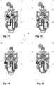
- Figures 21 to 24 show some intermediate steps of inserting a nozzle insert 6.
- a side gate nozzle 1 usually comprises a supply block 2, a distribution block 3 and a nozzle block 4 interconnected to each other in an axial direction (here z-direction).
- the nozzle block 4 comprises at least one nozzle recess 5, in which a nozzle insert 6 is arranged as described hereinafter in more detail.
- the nozzle insert 6 is in the assembled state held in the axial direction preferably held by a set screw 7 directly or indirectly interconnected to the nozzle block 4.
- the set screw 7 expands completely across the nozzle recess 5.
- a diameter of the set screw 7 is larger than a width 29 of the nozzle recess 5 in a lateral direction 18.
- the set screw 7 interacts with an inside thread 15 arranged in an upper area of the corresponding nozzle recess 5.
- the inside thread 15 extends in two opposite side walls 16 of the nozzle recess 5 as best visible in Figures 3 and 12 . It is arranged in an upper area of the nozzle recess 5 above the nozzle insert 6. Thereby the nozzle insert 6 in the mounted position can be pressed in a controlled and individual manner against a bottom 8 of the nozzle recess 5.
- the set screw 7 is not interacting directly with the nozzle block 4. Instead it is arranged in a separate cover plate 17.
- the cover plate 17 allows direct access to the set screws 7 from the outside. However, when the cover plate 17 is removed, e.g. for maintenance of one of the nozzle inserts 6, all remaining nozzle inserts 6 become loose too.
- the nozzle insert 6 For the melt to be transported without leakage the nozzle insert 6 comprises an inlet opening 9 which is usually pressed directly by the respective set screw 7 against an outlet opening 10 arranged at the bottom of the nozzle recess 5. As best visible in Figures 3 , 5 , 7 and 18 a good sealing between the inlet opening 9 of the nozzle insert 6 and the outlet opening 10 is achieved when the set screw 7 is arranged concentric with respect to the respective outlet opening 10 in the bottom 8. This way the applied sealing pressure can be evenly distributed. At least one nozzle tip 11 pointing in outward direction 12 is attached to the nozzle insert 6 as illustrated in Figures 5 and 9 . The melt is in all shown variations transported from the inlet opening 9 of the nozzle insert 6 to the thereto attached nozzle tip 11 via an insert melt channel 30 arranged inside the nozzle insert 6 interconnecting the inlet opening 9 and the nozzle tip 11.
- the nozzle insert 6 is arranged displaceable with respect to the outward direction 12.
- the nozzle block 4 comprises at least one guiding groove 21 in the outward direction 12 into which a pin-shaped retaining means 22 of the nozzle insert 6 engage. This way a displacement of the nozzle insert 6 in the outward direction 12 during assembly is guided by the at least one guiding groove 21.
- the guiding groove 21 is at least partially arranged in a wall of the nozzle recess 5.
- two or more nozzle inserts 6 can be arranged in one nozzle recess 5, in the case at hand there are two nozzle inserts 6 arranged in a common nozzle recess 5.
- the nozzle insert 6 is held during operation in the outward direction 12 against the direction of the melt flow 13 by a first spacer 14 illustrated e.g. in Figure 7 .
- the first spacer 14 at least partially consists of a material with a smaller coefficient of thermal expansion than the material of the nozzle block 4.
- the nozzle insert 6 is held in the direction of the melt flow 13 during operation by the pin-shaped retaining means 22 in contact with an end section 23 of the guiding groove 21.
- the retaining means 22 are integrally formed with the nozzle insert 6 and are block-shaped.
- At least two neighboring nozzle inserts 6 are spaced in a lateral direction 18 relative to each other by a laterally movable second spacer 19.
- the second spacer 19 best visible in Figure 12 at least partially consists of a material with a smaller coefficient of thermal expansion than the material of the nozzle block 4.
- cover plate 17 of the side gate nozzle 1 comprises an alignment through-hole 20 in the axial direction z as illustrated in Figure 4 to temporarily interconnect in the mounted state the cover plate 17 to the nozzle block 4 in a torsionally resistant manner.
- cover plate 17 is mounted to the mold plate, as visible in Figures 16 to 18 .
- Figures 16 to 18 show another aspect of the disclosure being directed to an injection mold 24 which comprises at least one cavity module 25 which comprises at least one cavity half 26 connected to a side gate nozzle 1.
- the injection mold 24 illustrated in Figure 16 comprises four cavity modules 25 being arranged on two pairs, wherein between the two cavity modules 25 of each pair a side gate nozzle 1 as illustrated in Figure 10 is arranged.
- Each cavity module 25 comprises a cavity half 26 per nozzle insert 6 / nozzle tip 11.
- the cavity module 25 further comprises at least one nozzle tip recess 27 connected to the cavity half 26 for accommodating a nozzle tip 11 of the side gate nozzle 1 and forming a detachable connection between the nozzle tip 11 and the nozzle tip recess 27.
- FIG. 18 a partial cross-sectional illustration of the injection mold 24 of Figure 16 , which further illustrates that at least one nozzle tip recess 27 comprises a sealing section 28 interacting with the nozzle tip 11 in the assembled state to provide a sealing therebetween.
- Figure 17 a detailed view of a side gate nozzle 1 of the injection mold 24 of Figure 16 is displayed showing the side gate nozzle 1 arranged between two cavity modules 25.
- a high efficiency in inserting and/ or removing of nozzle inserts 6 during maintenance and/ or assembly is possible when injection mold 24 is combined with a side gate nozzle 1 comprising an in an outward direction displaceably arranged nozzle insert 6.
- This allows inserting and removing nozzle inserts 6 without the need to separate the side gate nozzle blocks 4 from the cavity module.
- Figure 18 makes it possible to understand that an assembly of a nozzle insert 6 into the injection mold 24 with an inserted side gate nozzle 1 may comprise the following steps. When a nozzle insert 6 is inserted into the nozzle recess 5 it is moved in the axial direction z until the retaining means 22 engage into the guiding groove 21.
- the nozzle insert 6 is moved in outward direction 12, while being guided by the retaining means 22 in the guiding groove 21, until the nozzle tip 11 slides in the nozzle tip recess 27. In this position the retaining means 22 is in contact with the end section 23 of the guiding groove. In a next step the position of the nozzle insert 6 is secured in the outward direction 12, x when the first spacer 14 is inserted in the axial direction z and the set screw 7 is applied and tightened.
- the seventh variation of the side gate nozzle 1, as shown in Figures 19 to 24 comprises a rotationally symmetrical nozzle bock 4.
- the side gate nozzle 1 comprises in this variation four symmetrically arranged anti-rotation elements 36 extending in a radial direction from the outside of the nozzle block 4 for an easy and secure insertion of the side gate nozzle1 into an injection mold 24 (not shown).
- the anti-rotation elements 36 are pin-shaped elements.
- the seventh variation of the side gate nozzle 1 comprises a heating element 32 arranged in a groove 33 on the outside of the nozzle and distribution block 3, 4.
- the groove 33 encircles the nozzle and distribution block 3, 4 in a meandering manner.
- the heating element 32 comprises a meandrous turn between two respective neighboring nozzle recesses 5 and its comprises longitudinal sections towards the meandrous turn and away from the meandrous turn in the axial direction.
- the shown variation comprises multiple meandrous turns.
- the nozzle block 4 comprises a skirt-like projection 34 per nozzle recess 5 extending in a radial direction from the nozzle block recess 5 for preventing damage to the respective nozzle insert 6, especially during assembly of the side gate nozzle 1 in the injection mold 24 (not shown) and/or an individual nozzle insert 6.
- the projection 34 in the shown variation is arranged around the respective nozzle recess 5 extending with an essentially U-shaped cross-section in the radial direction from the bottom 8 and the side walls 16 of the nozzle recess 5.
- the side gate nozzle 1 comprises at least one guiding means 35 protruding from both opposite side walls 16 of the nozzle recess 5 to limit the movement of the nozzle insert 5 in the axial direction z during the intermediate step of the installation shown in Figure 23 . This prevents an undesirable tilting of the nozzle insert 6 in the axial direction z.
- the guiding means 35 are arranged, at a height from the bottom of the nozzle recess 5 in the axial direction equal to the height 38 of the nozzle insert 6, illustrated in Figure 20 .
- the guiding means 35 are in the shown variation formed as protrusions from both side walls 16 of the nozzle recess 5 in the lateral direction 18.
- the nozzle insert 6 comprises two lead in recesses 37 each extending along a side of the nozzle insert 6 to temporarily accommodate during insertion into the nozzle recess 5 the guiding means 35 formed as a protrusion as best visible in Figure 22 .
Landscapes
- Engineering & Computer Science (AREA)
- Manufacturing & Machinery (AREA)
- Mechanical Engineering (AREA)
- Injection Moulding Of Plastics Or The Like (AREA)
- Moulds For Moulding Plastics Or The Like (AREA)
Description
- The present disclosure is directed to a side gate nozzle and a thereto related injection mold for injection molding plastics and other thermoplastic materials.
- From the prior art, side gate nozzles comprising several nozzle tips are known. The nozzle tips, which in the side gate nozzle are usually arranged sideways with respect to the general direction of the side gate nozzle, are in fluid communication with a common nozzle block. The nozzle block is, with respect to the melt flow direction, arranged upstream. With respect to the melt flow direction arranged downstream, the nozzle tips are each interconnected to a cavity suitable to receive during production melted plastic material via the nozzle tip. While the nozzle tips and the thereto interconnected nozzle block are kept on a temperature above the melting temperature of the plastic material, tool plates between which at least one cavity is arranged, is kept on a temperature significantly below the melting temperature of the plastic material such that the plastic material injected into the cavity is cured immediately when in contact with a cavity wall to form the plastic part efficiently. The overall construction of the side gate nozzle must be done in a way, that geometric deformation which occurs due to different temperatures and changes during heat up and operation has no negative impact on the overall system and performance. In addition, it is advantageous when the nozzle tips can be easily removed, respectively disengaged from the related cavity, e.g. for maintenance reason, wherein a precise alignment of the nozzle tips need to be ensured. From the prior art, several attempts are known to address the above problem. A selection is briefly described hereinafter.
-
SE500650C2 was first published in August 1994 in the name of Hans Müller -
DE19649621A1 was first published in June 1998 in the name of EWIKON Heißkanalsysteme GmbH. It relates to an adapter for use with a nozzle manifold of a hot runner injection molding system for fluidly connecting at least two runner sections and thereby distribute and conduct melt to cavities of an injection mold, includes a plug having at least one end face formed with a first opening for fluid connection to one runner section and a cylindrical or conical wall surface formed with a second opening for fluid connection to another runner section and extending at an angle with respect to the one end face, and a force-applying unit so acting upon the plug as to urge the end face and the wall surface into a fluid-tight pressure fit upon mating surfaces of the nozzle manifold. -
DE202008005073U1 was first published in August 2007 in the name of EWIKON Heißkanalsysteme GmbH. It relates to a hot runner nozzle for lateral injection of plastic components. The nozzle includes a multi-part nozzle body including at least one tip element which protrudes outwardly over a circumferential area of the nozzle body. The multi-part nozzle body further includes a nozzle body clamping disk section and a nozzle body base section having an axial side that has at least one recess arranged on the axial side to accommodate the at least one tip element. -
DE102009048368A1 was first published in April 2011 in the name of HASCO Hasenclever GmbH. It relates to an injection nozzle for guiding melt mass, in particular in a plastic injection mold, by means of which melt mass can be supplied to several mold cavities during an injection molding cycle, wherein the melt mass can be guided from a master channel formed at least partially in the nozzle body into at least two branch channels, wherein the branch channels are formed at least partially by a nozzle tip which is provided with an outlet opening via which the melt mass can be supplied to the mold cavity, wherein each nozzle tip can be positioned in a bearing seat and can be detachably fastened to the nozzle body by means of at least one retaining element. -
CA2785980AA was first published in June 2012 in the name of Husky Injection Molding Systems. -
EP2639035A1 was first published in September 2013 in the name of Mold-Masters 2007 Ltd. It relates to an edge-gated injection molding apparatus having an injection manifold assembly for distributing a melt stream of moldable material to a plurality of mold cavities aligned on opposing sides of the injection manifold assembly. The injection manifold assembly includes a plurality of melt outlets with each melt outlet being in fluid communication with a respective mold cavity, and a plurality of biasing components disposed along a centerline of the injection manifold assembly. A nozzle seal is disposed between each injection manifold assembly melt outlet and its corresponding mold cavity. Each biasing component is disposed between a pair of melt outlets and corresponding nozzle seals for biasing the melt outlets and nozzle seals outward from the centerline of the injection manifold assembly toward their respective mold cavities and applying a preload thereto. -
EP2308664A1 was first published in April 2011 in the name of Hasco Hasenclever GmbH & Co. KG and relates to an injection nozzle for guiding melt mass in a plastic injection mold. The injection nozzle comprises cavities to which the melt mass is introduced in an injection molding cycle. The melt mass is introduced from a stem channel into two branch ducts, which are partially formed by a nozzle tip. The nozzle tip is equipped with a discharge opening over which the melt mass is introduced into the mold cavities. Each nozzle tip is positioned in a bearing seat and is mounted by at least one retaining element, which form a second mounting surface for the nozzle tip. -
KR20130139505A was first published in December 2013 in the name of Heo Nam Wuk - In difference to the prior art, a side gate nozzle according to the disclosure usually comprises a supply block, a distribution block and a nozzle block interconnected to each other in an axial direction. Depending on the field of application, at least the distribution block and the nozzle block may be integrally formed.
- The nozzle block usually comprises at least one nozzle recess extending in an outward direction. In the nozzle recess at least one nozzle insert comprising at least one nozzle tip is arranged. The nozzle block may comprise multiple nozzle inserts each arranged in a respective nozzle recess or in a common nozzle recess. If present, the nozzle inserts are preferably arranged on the same level with respect to the general axial direction.
- The at least one nozzle insert is in the mounted state preferably held, at least in the axial direction, by a set screw directly interconnected to the nozzle block. Thereby more accurate adjustment becomes possible. According to the invention, the set screw expands at least partially across the nozzle recess. According to the invention, the diameter of the set screw is larger than the diameter of the nozzle recess in a lateral direction.
- According to the invention, the set screw interacts with an inside thread, which is preferably arranged at two opposite side walls of the nozzle recess. Thereby unwanted movements, e.g. lifting off etc. can be safely prevented although other adjustments, e.g. in transversal direction and/or in the direction of the nozzle due to thermal expansion, may remain possible if necessary.
- If present, a cover plate may be mechanically interconnected to the nozzle block and a mold plate of the injection mold in which the side gate nozzle is arranged, to compensate torque when setting the set screws. The cover plate preferably comprises openings arranged coaxial to the below arranged set screws, thereby allowing access to the set screws in the mounted state. In certain cases, the set screws can be arranged in a cover plate arranged above the nozzle inserts.
- For each nozzle tip, the nozzle insert comprises an inlet opening which is pressed by the set screw against an outlet opening arranged at the bottom of the nozzle recess. A good sealing performance between the inlet opening of the nozzle insert and the outlet opening is achieved when the set screw is arranged concentric with respect to the outlet opening as in this way the applied pressure can is evenly distributed.
- The at least one nozzle tip attached to a nozzle insert is preferably pointing in the respective outward direction similar to the recess. Depending on the field of application, two or more nozzle tips can be attached to a common nozzle insert.
- Depending on the field of application, the nozzle block may have a cylindrical shape or a cuboid shape depending on the arrangement of the nozzle inserts, respectively the nozzle tips and their interconnection to the thereto related cavities.
- For assembly and/or maintenance the nozzle inserts may be arranged displaceable in the nozzle recess with respect to the outward direction. Thereby it becomes possible to interconnect the nozzle inserts in a slidable manner with respect to the cavity.
- Furthermore, the nozzle block may comprise at least one guiding groove in the outward direction into which a pin-shaped retaining means usually attached to the nozzle insert engages and limits the movement of said nozzle insert in the outward direction. The retaining means can be integrally formed with the nozzle insert or be designed as a separate element attached thereto. The guiding groove may e.g. be at least partially arranged at a wall of the nozzle recess. The nozzle insert during operation is preferably supported in the inward direction, against the direction of the melt flow, by a spacer (first spacer). The spacer can be removably attached to the nozzle block and/or distribution block. The first spacer may at least partially consist of a material with a smaller coefficient of thermal expansion than the material of the nozzle block, however various materials are also possible like steel or titanium alloys. In the opposite direction, the nozzle insert is held in the direction of the melt flow during operation by the pin-shaped retaining means in contact with an end section of the guiding groove. If appropriate the pin-shaped retaining means can have a rectangular cross-section in order to contact a correspondingly formed end section of the guiding groove in a planar manner in order to prevent misalignment of the nozzle tip with respect to the cavity.
- In some variations the spacer can be formed as a hollow cylinder or a beam. The spacer can be attached to the nozzle block and/or distribution block by means of at least one screw.
- Good results are possible when the spacer supports the nozzle insert in an elastic pretensioned manner, i.e. against the force of a spring, in the outward direction via a contact surface. This can be achieved in that the spacer is designed as a spring e.g. in that it is formed as a hollow cylinder which comprises slits in the axial direction allowing a spring like displacement of the hollow cylinder wall in a radial outward direction and thus an elastic support of the nozzle inserts during operation and/or assembly.
- In some variations at least two nozzle inserts are arranged neighboring to each other. If appropriate, their lateral position can be defined by a second spacer which can be arranged laterally movable. Preferably the second spacer at least partially consists of a material with a smaller coefficient of thermal expansion than the material of the nozzle block.
- Good results can be achieved when the first and/or the second spacer are made from a material having a low coefficient of thermal expansion, such as Invar® or the like.
- The cover plate of the side gate nozzle may comprise at least one alignment through-hole in the axial direction to temporarily interconnect in the mounted state the cover plate to the nozzle block in a torsionally resistant manner. The nozzle block may comprise at least one opening which is preferably in the assembled state coaxially aligned with an associated through-hole of the cover plate. A temporary torsionally resistant connection between the cover plate and the nozzle block can be established by inserting an elongated connection device into the through-hole and extending into the opening. By forming a form fit with the through hole and/ or the opening the connection device provides a torsionally resistant connection between the cover plate and the nozzle block. If appropriate, especially when having a rotational symmetrical shape, the side gate nozzle can be interconnected to the injection mold by at least one anti-rotation element preventing damage of the nozzle tips of the side gate nozzle, e.g. when applying torque to the set screws. The anti-rotation element is arranged between the side gate nozzle and the injection mold and supports the side gate nozzle in circumferential direction with respect to the injection mold. Thereby, the torque applied to the set screw is kept away from the nozzle tips when extending into the respective cavities of the injection mold. If present, the at least one anti-rotation element can extend essentially in a radial direction from the outside of the nozzle block and/or the distribution block for an easy and secure insertion of the side gate nozzle into the injection mold. The anti-rotation element is preferably configured to engage during assembly of the mold with corresponding reception indentations and/or protrusions in the mold plate in a form locking manner. The anti-rotation element can be formed, depending on the design e.g. as a pin. In addition to the circumferential support the anti-rotation element may also provide a detachable connection between the side gate nozzle and the injection mold in the radial and/or axial direction.
- For optimal performance of the side gate nozzle a heating element can be arranged at least partially in a groove on the outside of the nozzle block and/or the distribution block to control the temperature of the melt. Preferably the heating element comprises at least one meandrous turn between two neighboring nozzle recesses. The heating element can be formed as a band-like, a cable-like, a flat or a tubular heating element arranged in the groove. The groove may at least partially encircle the nozzle block and/or the distribution block in a meandering or sinusoidal manner. In addition, a temperature sensor may be arranged in the nozzle block and/or the distribution block for a precise regulation of the meld temperature.
- For aligning the nozzle insert in a lateral direction and in that the nozzle tip with respect to the cavity, in particular during insertion of the nozzle insert, a support means may be arranged in the outward direction adjacent to the nozzle recess. If present, the support means extends at least partially in a radial direction to support the nozzle insert at least in the lateral direction during installation and/or operation. Depending on the design the support means can be formed as at least one projection extending from the nozzle block in a radial direction. Preferably the projection may at least partially be arranged around the nozzle recess and in a flush manner from the two side walls of the nozzle recess. In some variations one projection per nozzle recess extends with an essentially U-shaped cross-section in the radial direction from the bottom and the side walls of the nozzle recess.
- For an easy and damage-free insertion of a nozzle insert into a nozzle recess of the side gate nozzle, the side gate nozzle may comprise at least one guiding means protruding from at least one of two opposite side walls of the nozzle recess to prevent an unwanted tilting of the nozzle insert in the axial direction during installation and/or operation. It is preferable that guiding means are arranged, such that the distance between the guiding means and the bottom of the nozzle recess is essentially equal to the height if the nozzle insert in the axial direction such that during installation and/or operation the guiding means at least temporarily interact with a top face of the nozzle insert. The guiding means may be formed as a protrusion from a side wall of the nozzle recess in the lateral direction. In some variations the guiding means can extend between the two opposite side walls of the nozzle recess.
- Good results are possible when the nozzle insert comprises a lead in recess extending along a side of the nozzle insert to temporarily accommodate during insertion into the nozzle recess the guiding means formed as a protrusion.
- Another aspect of the disclosure is directed to an injection mold which usually comprises at least one cavity module which comprises at least one cavity half connected to a side gate nozzle as described above. Preferably the cavity module comprises at least one nozzle tip recess connected to the cavity half for accommodating a nozzle tip of the side gate nozzle and forming a detachable connection between the nozzle tip and the nozzle tip recess.
- A high efficiency in inserting and/ or removing of nozzle inserts during maintenance and/ or assembly is possible when an injection mold is combined with a side gate nozzle comprising a in an outward direction displaceable arranged nozzle insert. This allows inserting and removing nozzle inserts without the need to separate the side gate nozzle blocks from the cavity module. An assembly of a nozzle insert into the injection mold with attached side gate nozzle may comprise the following steps. When a nozzle insert is inserted into the nozzle recess it is moved in the axial direction until the retaining means engage into the guiding groove. Afterwards the nozzle insert is moved in outward direction while being guided by the retaining means in the guiding groove, until the nozzle tip slides in the nozzle tip recess. In this position the retaining means is in contact with the end region of the guiding groove. In a next step the position of the nozzle insert is secured in the outward direction when the first spacer is inserted in the axial direction and the set screw is applied and tightened.
- Preferably the at least one nozzle tip recess comprises a sealing section interacting with the nozzle tip in the mounted state to provide a sealing there between.
- It is to be understood that both the foregoing general description and the following detailed description present embodiments, and are intended to provide an overview or framework for understanding the nature and character of the disclosure. The accompanying drawings are included to provide a further understanding, and are incorporated into and constitute a part of this specification. The drawings illustrate various embodiments, and together with the description serve to explain the principles and operation of the concepts disclosed.
- The herein described invention will be more fully understood from the detailed description given herein below and the accompanying drawings which should not be considered limiting to the invention described in the appended claims. The drawings are showing:
- Fig. 1
- a first variation of a side gate nozzle in an exploded view;
- Fig. 2
- the first variation according to
Figure 1 in a perspective manner and partially sectioned; - Fig. 3
- detail A according to
Figure 2 in a magnified manner; - Fig. 4
- a second variation of a side gate nozzle in an exploded view;
- Fig. 5
- a section view across the variation according to
Figure 4 along section line BB; - Fig. 6
- a third variation of a side gate nozzle in an exploded view;
- Fig. 7
- a section view across the variation according to
Figure 6 along section line CC; - Fig. 8
- a fourth variation of a side gate nozzle in an exploded view;
- Fig. 9
- the fourth variation according to
Figure 8 in a perspective manner and partially sectioned; - Fig. 10
- a fifth variation in a perspective view;
- Fig. 11
- the fifth variation in an exploded view;
- Fig. 12
- detail E according to
Figure 11 ; - Fig. 13
- a sixth variation of a side gate nozzle in a perspective view;
- Fig. 14
- a section view across the variation according to
Figure 13 ; - Fig. 15
- the sixth variation in an exploded view;
- Fig. 16
- the fifth variation according to
Figures 10 through 12 arranged in an injection mold; - Fig. 17
- detail H according to
Figure 16 ; - Fig. 18
- a section view along section line GG according to
Figure 16 ; - Fig. 19
- a seventh variation of a side gate nozzle in a perspective and partially exploded and partially sectional view;
- Fig. 20
- the seventh variation of
Figure 19 from a different viewing angle; - Fig. 21
- the seventh variation of a side gate nozzle during assembly;
- Fig. 22
- the seventh variation of a side gate nozzle during assembly;
- Fig. 23
- the seventh variation of a side gate nozzle during assembly; and
- Fig. 24
- the seventh variation of a side gate nozzle during assembly.
- Reference will now be made in detail to certain embodiments, examples of which are illustrated in the accompanying drawings, in which some, but not all features are shown. Indeed, embodiments disclosed herein may be embodied in many different forms and should not be construed as limited to the embodiments set forth herein; rather, these embodiments are provided so that this disclosure will satisfy applicable legal requirements. Whenever possible, like reference numbers will be used to refer to like components or parts.
-
Figure 1 is showing a first variation of aside gate nozzle 1 in an exploded view.Figure 2 shows the first variation of theside gate nozzle 1 according toFigure 1 in a perspective manner and partially sectioned.Figure 3 shows detail A according toFigure 2 in a magnified manner.Figure 4 shows a second variation of theside gate nozzle 1 in an exploded view.Figure 5 shows a section view along section line BB according toFigure 4 .Figure 6 shows a third variation of theside gate nozzle 1 in an exploded view.Figure 7 shows a section view along section line CC ofFigure 6 .Figure 8 shows a fourth variation of theside gate nozzle 1 in an exploded view.Figure 9 shows the fourth variation according toFigure 8 in a perspective manner and partially sectioned.Figure 10 shows a fifth variation of theside gate nozzle 1 in a perspective view.Figure 11 shows the fifth variation in an exploded view. Figure 12 shows Detail E according toFigure 11 .Figure 13 shows a sixth variation of theside gate nozzle 1 in a perspective view.Figure 14 shows a section view across the variation according toFigure 13 .Figure 15 shows the sixth variation according toFigure 13 in an exploded view.Figure 16 shows the fifth variation according toFigure 10 through Figure 12 arranged in aninjection mold 24.Figure 17 shows Detail H according toFigure 16 and Figure 18 shows a section view along section line GG according toFigure 16 .Figure 19 shows a seventh variation of aside gate nozzle 1 in a perspective and partially exploded and partially sectional view andFigure 20 shows the seventh variation ofFigure 19 from a different viewing angle.Figures 21 to 24 show some intermediate steps of inserting anozzle insert 6. - As e.g. visible in
Figure 1 through Figure 20 aside gate nozzle 1 according to the disclosure usually comprises asupply block 2, adistribution block 3 and anozzle block 4 interconnected to each other in an axial direction (here z-direction). Thenozzle block 4 comprises at least onenozzle recess 5, in which anozzle insert 6 is arranged as described hereinafter in more detail. Thenozzle insert 6 is in the assembled state held in the axial direction preferably held by aset screw 7 directly or indirectly interconnected to thenozzle block 4. - In the variations according to
Figure 1 through Figure 7 andFigure 10 through Figure 12, theset screw 7 expands completely across thenozzle recess 5. As e.g. visible inFigure 6 , a diameter of theset screw 7 is larger than awidth 29 of thenozzle recess 5 in alateral direction 18. In these variations theset screw 7 interacts with aninside thread 15 arranged in an upper area of thecorresponding nozzle recess 5. Theinside thread 15 extends in twoopposite side walls 16 of thenozzle recess 5 as best visible inFigures 3 and12 . It is arranged in an upper area of thenozzle recess 5 above thenozzle insert 6. Thereby thenozzle insert 6 in the mounted position can be pressed in a controlled and individual manner against abottom 8 of thenozzle recess 5. - In the functionally different variation according
Figure 13 through Figure 15 , theset screw 7 is not interacting directly with thenozzle block 4. Instead it is arranged in aseparate cover plate 17. Thecover plate 17 allows direct access to theset screws 7 from the outside. However, when thecover plate 17 is removed, e.g. for maintenance of one of the nozzle inserts 6, all remaining nozzle inserts 6 become loose too. - For the melt to be transported without leakage the
nozzle insert 6 comprises aninlet opening 9 which is usually pressed directly by therespective set screw 7 against anoutlet opening 10 arranged at the bottom of thenozzle recess 5. As best visible inFigures 3 ,5 ,7 and18 a good sealing between theinlet opening 9 of thenozzle insert 6 and theoutlet opening 10 is achieved when theset screw 7 is arranged concentric with respect to the respective outlet opening 10 in thebottom 8. This way the applied sealing pressure can be evenly distributed. At least onenozzle tip 11 pointing inoutward direction 12 is attached to thenozzle insert 6 as illustrated inFigures 5 and9 . The melt is in all shown variations transported from theinlet opening 9 of thenozzle insert 6 to the thereto attachednozzle tip 11 via aninsert melt channel 30 arranged inside thenozzle insert 6 interconnecting theinlet opening 9 and thenozzle tip 11. - As can be seen from the sectional illustration of
Figure 5 for assembly and/or maintenance of aside gate nozzle 1 according to the disclosure thenozzle insert 6 is arranged displaceable with respect to theoutward direction 12. In order to achieve that, thenozzle block 4 comprises at least one guidinggroove 21 in theoutward direction 12 into which a pin-shaped retaining means 22 of thenozzle insert 6 engage. This way a displacement of thenozzle insert 6 in theoutward direction 12 during assembly is guided by the at least one guidinggroove 21. The guidinggroove 21 is at least partially arranged in a wall of thenozzle recess 5. As can be seen fromFigure 8 two or more nozzle inserts 6 can be arranged in onenozzle recess 5, in the case at hand there are twonozzle inserts 6 arranged in acommon nozzle recess 5. Thenozzle insert 6 is held during operation in theoutward direction 12 against the direction of themelt flow 13 by afirst spacer 14 illustrated e.g. inFigure 7 . Preferably thefirst spacer 14 at least partially consists of a material with a smaller coefficient of thermal expansion than the material of thenozzle block 4. In the opposite direction, thenozzle insert 6 is held in the direction of themelt flow 13 during operation by the pin-shaped retaining means 22 in contact with anend section 23 of the guidinggroove 21. However, in the seventh variation of theside gate nozzle 1, as shown inFigures 19 to 24 , the retaining means 22 are integrally formed with thenozzle insert 6 and are block-shaped. - In some variations illustrated in
Figures 10 to 12 at least two neighboring nozzle inserts 6 are spaced in alateral direction 18 relative to each other by a laterally movablesecond spacer 19. Thesecond spacer 19 best visible inFigure 12 at least partially consists of a material with a smaller coefficient of thermal expansion than the material of thenozzle block 4. - In some variations the
cover plate 17 of theside gate nozzle 1 comprises an alignment through-hole 20 in the axial direction z as illustrated inFigure 4 to temporarily interconnect in the mounted state thecover plate 17 to thenozzle block 4 in a torsionally resistant manner. In some variations thecover plate 17 is mounted to the mold plate, as visible inFigures 16 to 18 . -
Figures 16 to 18 , show another aspect of the disclosure being directed to aninjection mold 24 which comprises at least onecavity module 25 which comprises at least onecavity half 26 connected to aside gate nozzle 1. Theinjection mold 24 illustrated inFigure 16 comprises fourcavity modules 25 being arranged on two pairs, wherein between the twocavity modules 25 of each pair aside gate nozzle 1 as illustrated inFigure 10 is arranged. Eachcavity module 25 comprises acavity half 26 pernozzle insert 6 /nozzle tip 11. Thecavity module 25 further comprises at least onenozzle tip recess 27 connected to thecavity half 26 for accommodating anozzle tip 11 of theside gate nozzle 1 and forming a detachable connection between thenozzle tip 11 and thenozzle tip recess 27. This is best visible in theFigure 18 , a partial cross-sectional illustration of theinjection mold 24 ofFigure 16 , which further illustrates that at least onenozzle tip recess 27 comprises asealing section 28 interacting with thenozzle tip 11 in the assembled state to provide a sealing therebetween. InFigure 17 a detailed view of aside gate nozzle 1 of theinjection mold 24 ofFigure 16 is displayed showing theside gate nozzle 1 arranged between twocavity modules 25. - A high efficiency in inserting and/ or removing of nozzle inserts 6 during maintenance and/ or assembly is possible when
injection mold 24 is combined with aside gate nozzle 1 comprising an in an outward direction displaceably arrangednozzle insert 6. This allows inserting and removingnozzle inserts 6 without the need to separate the side gate nozzle blocks 4 from the cavity module.Figure 18 makes it possible to understand that an assembly of anozzle insert 6 into theinjection mold 24 with an insertedside gate nozzle 1 may comprise the following steps. When anozzle insert 6 is inserted into thenozzle recess 5 it is moved in the axial direction z until the retaining means 22 engage into the guidinggroove 21. Afterwards thenozzle insert 6 is moved inoutward direction 12, while being guided by the retaining means 22 in the guidinggroove 21, until thenozzle tip 11 slides in thenozzle tip recess 27. In this position the retaining means 22 is in contact with theend section 23 of the guiding groove. In a next step the position of thenozzle insert 6 is secured in theoutward direction 12, x when thefirst spacer 14 is inserted in the axial direction z and theset screw 7 is applied and tightened. - The seventh variation of the
side gate nozzle 1, as shown inFigures 19 to 24 comprises a rotationallysymmetrical nozzle bock 4. Theside gate nozzle 1 comprises in this variation four symmetrically arrangedanti-rotation elements 36 extending in a radial direction from the outside of thenozzle block 4 for an easy and secure insertion of the side gate nozzle1 into an injection mold 24 (not shown). Theanti-rotation elements 36 are pin-shaped elements. - Furthermore, the seventh variation of the
side gate nozzle 1 comprises a heating element 32 arranged in agroove 33 on the outside of the nozzle anddistribution block Figures 19 and 20 thegroove 33 encircles the nozzle anddistribution block Figures 21 to 24 the heating element 32 comprises a meandrous turn between two respective neighboring nozzle recesses 5 and its comprises longitudinal sections towards the meandrous turn and away from the meandrous turn in the axial direction. The shown variation comprises multiple meandrous turns. - As best visible in
Figures 21 to 24 thenozzle block 4 comprises a skirt-like projection 34 pernozzle recess 5 extending in a radial direction from thenozzle block recess 5 for preventing damage to therespective nozzle insert 6, especially during assembly of theside gate nozzle 1 in the injection mold 24 (not shown) and/or anindividual nozzle insert 6. Theprojection 34 in the shown variation is arranged around therespective nozzle recess 5 extending with an essentially U-shaped cross-section in the radial direction from thebottom 8 and theside walls 16 of thenozzle recess 5. - For an easy and damage-free insertion of a
nozzle insert 6 into anozzle recess 5 of theside gate nozzle 1, theside gate nozzle 1 comprises at least one guiding means 35 protruding from bothopposite side walls 16 of thenozzle recess 5 to limit the movement of thenozzle insert 5 in the axial direction z during the intermediate step of the installation shown inFigure 23 . This prevents an undesirable tilting of thenozzle insert 6 in the axial direction z. The guiding means 35 are arranged, at a height from the bottom of thenozzle recess 5 in the axial direction equal to theheight 38 of thenozzle insert 6, illustrated inFigure 20 . The guiding means 35 are in the shown variation formed as protrusions from bothside walls 16 of thenozzle recess 5 in thelateral direction 18. As visible inFigures 19 to 24 thenozzle insert 6 comprises two lead inrecesses 37 each extending along a side of thenozzle insert 6 to temporarily accommodate during insertion into thenozzle recess 5 the guiding means 35 formed as a protrusion as best visible inFigure 22 . - Rather, the words used in the specification are words of description rather than limitation, and it is understood that various changes may be made. The invention is set out in the appended set of claims.
-
- 1
- Side gate nozzle
- 2
- Supply block
- 3
- Distribution block
- 4
- Nozzle block
- 5
- Nozzle recess
- 6
- Nozzle insert
- 7
- Set screw
- 8
- Bottom (nozzle recess)
- 9
- Inlet opening (nozzle insert)
- 10
- Outlet opening (distribution block)
- 11
- Nozzle tip
- 12
- Outward direction (nozzle tip)
- 13
- Melt flow
- 14
- First spacer
- 15
- Inside thread (for set screw)
- 16
- Side wall (nozzle recess)
- 17
- Cover plate
- 18
- Lateral direction (recess/ insert)
- 19
- Second spacer
- 20
- Through-hole
- 21
- Guiding groove
- 22
- Retaining means
- 23
- End section of the guiding groove
- 24
- Injection mold
- 25
- Cavity module
- 26
- Cavity half
- 27
- Nozzle tip recess
- 28
- Sealing section
- 29
- Width (nozzle recess)
- 30
- Insert melt channel
- 31
- Diameter (set screw)
- 32
- Heating element
- 33
- Groove (heating element)
- 34
- Projection (nozzle block)
- 35
- Guiding means
- 36
- Anti-rotation element
- 37
- Lead-in recess (nozzle insert)
- 38
- Height (nozzle insert)
- 39
- Mold plate
Claims (19)
- Side gate nozzle (1) comprising a supply block (2), a distribution block (3) and a nozzle block (4) interconnected to each other in an axial direction (z),a. wherein the nozzle block (4) comprises at least one nozzle recess (5), in which a nozzle insert (6) is arranged which in the axial direction (z) is held by a set screw (7) interconnected to the nozzle block (4),
characterized in thatb. the set screw (7) expands at least partially across the nozzle recess (5) ;c. the diameter (31) of the set screw (7) is bigger than the width (29) of the nozzle recess (5) in a lateral direction (18),d. the set screw (7) interacts with an inside thread (15) arranged at two opposite side walls (16) of the nozzle recess (5). - The side gate nozzle (1) according to claim 1, wherein the set screw (7) is arranged in a cover plate (17).
- The side gate nozzle (1) according to at least one of the preceding claims, wherein the nozzle insert (6) comprises an inlet opening (9) which is pressed by the set screw (7) against an outlet opening (10) arranged at the bottom of the nozzle recess (5).
- The side gate nozzle (1) according to at least one of the preceding claims, wherein the set screw (7) is arranged concentric with respect to the outlet opening (10).
- The side gate nozzle (1) according to at least one of the preceding claims, wherein at least one nozzle tip (11) pointing in an outward direction (12) is attached to a nozzle insert (6).
- The side gate nozzle (1) according to at least one of the preceding claims, wherein the nozzle insert (6) for maintenance is arranged displaceable with respect to the inward direction.
- The side gate nozzle (1) according to claim 6, wherein the nozzle insert (6) during operation is held in the outward direction (12) against the direction of the melt flow (13) by a first spacer (14).
- The side gate nozzle (1) according to at least one of the preceding claims, wherein at least two nozzle inserts (6) are positioned in a lateral direction (18) relative to each other by a laterally movable second spacer (19).
- The side gate nozzle (1) according to at least one of the preceding claims, wherein a cover plate (17) comprises an alignment through-hole (20) in the axial direction to temporarily interconnect in the mounted state the cover plate (17) to the nozzle block (4) in a torsionally resistant manner.
- The side gate nozzle (1) according to at least one of the preceding claims, wherein the nozzle block (4) comprises at least one guiding groove (21) in the outward direction (12) into which a pin-shaped retaining means (22) of the nozzle insert (6) engages during assembly.
- The side gate nozzle (1) according claim 10, wherein the nozzle insert (6) is held in the direction of the melt flow (13) during operation by the pin-shaped retaining means (22) in contact with an end section (23) of the guiding groove (21).
- The side gate nozzle (1) according to at least one of the previous claims, wherein a heating element (32) is arranged in a groove (33) on the outside the nozzle block (4) and/or the distribution block (3).
- The side gate nozzle (1) according to claim 12, wherein the heating element (32) comprises at least one meandrous turn between two neighboring nozzle recesses (5).
- The side gate nozzle (1) according to at least one of the previous claims, wherein a support means (34) is arranged in the outward direction adjacent to the nozzle recess (5) extending at least partially in a radial direction to support the nozzle insert (5) in the lateral direction during installation and/or operation.
- The side gate nozzle (1) according to at least one of the previous claims, wherein a guiding means (35) protrudes from at least one of two opposite side walls (16) of the nozzle recess (5) to prevent a tilting of the nozzle insert (6) in the axial direction (z) during installation and/or operation.
- The side gate nozzle (1) according to claim 15, wherein the distance between the guiding means (35) and the bottom (8) of the nozzle recess (5) is essentially equal to the height (38) if the nozzle insert (6) in the axial direction (z), such that during installation and/or operation the guiding means (35) at least temporarily interact with a top face of the nozzle insert (6).
- An injection mold (24) comprising at least one cavity module (25) which comprises at least one cavity half (26) connected to a side gate nozzle (1) according any one of claims 1 to 15.
- The injection mold (24) according to claim 17, wherein the cavity module (25) comprises at least one nozzle tip recess (27) connected to the cavity half (26) for accommodating a nozzle tip (11) of the side gate nozzle (1) and forming a detachable connection between the nozzle tip (11) and the nozzle tip recess (27).
- The injection mold (24) according to claim 18, wherein the at least one nozzle tip recess (27) comprises a sealing section (28) interacting with the nozzle tip (11) in the mounted state to provide a sealing therebetween.
Applications Claiming Priority (2)
| Application Number | Priority Date | Filing Date | Title |
|---|---|---|---|
| DE102019127956.9A DE102019127956A1 (en) | 2019-10-16 | 2019-10-16 | SIDE INJECTION NOZZLE AND INJECTION MOLDING TOOL |
| PCT/EP2020/079266 WO2021074416A1 (en) | 2019-10-16 | 2020-10-16 | Side gate nozzle and injection mold |
Publications (2)
| Publication Number | Publication Date |
|---|---|
| EP4045268A1 EP4045268A1 (en) | 2022-08-24 |
| EP4045268B1 true EP4045268B1 (en) | 2024-09-18 |
Family
ID=72964683
Family Applications (1)
| Application Number | Title | Priority Date | Filing Date |
|---|---|---|---|
| EP20793640.2A Active EP4045268B1 (en) | 2019-10-16 | 2020-10-16 | Side gate nozzle and injection mold |
Country Status (5)
| Country | Link |
|---|---|
| US (1) | US12330358B2 (en) |
| EP (1) | EP4045268B1 (en) |
| CN (1) | CN114555323B (en) |
| DE (1) | DE102019127956A1 (en) |
| WO (1) | WO2021074416A1 (en) |
Families Citing this family (2)
| Publication number | Priority date | Publication date | Assignee | Title |
|---|---|---|---|---|
| DE102022103681B3 (en) | 2022-02-16 | 2023-05-17 | Thermoplay S.P.A. | SIDE GATE, TIP INSERT FOR A SIDE GATE AND INJECTION MOLD |
| US20250340000A1 (en) * | 2024-05-06 | 2025-11-06 | Progressive Components International Corporation | Gate insert for injection molding |
Family Cites Families (12)
| Publication number | Priority date | Publication date | Assignee | Title |
|---|---|---|---|---|
| SE9302492L (en) | 1993-07-23 | 1994-08-01 | Hans Mueller | Device for sidewall ingot with base plate |
| DE19649621B4 (en) | 1996-11-29 | 2007-08-02 | EWIKON Heißkanalsysteme GmbH & Co KG | Connection arrangement for melt channel sections in hot runners |
| DE202008005073U1 (en) | 2008-04-11 | 2008-07-03 | EWIKON Heißkanalsysteme GmbH & Co. KG | Hot runner nozzle for Seitenanspritzung |
| US7794228B2 (en) | 2008-04-29 | 2010-09-14 | Mold-Masters (2007) Limited | Injection molding apparatus having an edge-gated runnerless nozzle |
| DE202009004786U1 (en) | 2009-05-06 | 2010-09-23 | EWIKON Heißkanalsysteme GmbH & Co. KG | Hot runner nozzle for Seitenanspritzung |
| DE102009048368B4 (en) * | 2009-10-06 | 2013-07-04 | Hasco Hasenclever Gmbh + Co Kg | Injection nozzle for guiding melt mass, in particular in a plastic injection mold |
| CA2785980C (en) | 2010-02-01 | 2016-12-06 | Husky Injection Molding Systems Ltd. | Side gate nozzle assembly |
| DE102010049394B4 (en) * | 2010-10-26 | 2018-07-12 | Hasco Hasenclever Gmbh + Co Kg | Disassembly device for an injection nozzle |
| US8932046B2 (en) | 2012-03-16 | 2015-01-13 | Mold-Masters (2007) Limited | Edge-gated injection molding apparatus |
| KR101386361B1 (en) | 2012-06-13 | 2014-04-16 | 허남욱 | Nozzle device for side gate type hot runner injection mould |
| KR101326250B1 (en) | 2012-07-13 | 2013-11-11 | 주식회사 유도 | Injection moulding of side gate |
| DE102014009437A1 (en) | 2014-06-25 | 2016-01-21 | Otto Männer Innovation GmbH | Modular side pouring nozzle and casting mold |
-
2019
- 2019-10-16 DE DE102019127956.9A patent/DE102019127956A1/en active Pending
-
2020
- 2020-10-16 WO PCT/EP2020/079266 patent/WO2021074416A1/en not_active Ceased
- 2020-10-16 US US17/769,219 patent/US12330358B2/en active Active
- 2020-10-16 CN CN202080072952.8A patent/CN114555323B/en active Active
- 2020-10-16 EP EP20793640.2A patent/EP4045268B1/en active Active
Also Published As
| Publication number | Publication date |
|---|---|
| US20240116226A1 (en) | 2024-04-11 |
| CN114555323A (en) | 2022-05-27 |
| WO2021074416A1 (en) | 2021-04-22 |
| EP4045268A1 (en) | 2022-08-24 |
| CN114555323B (en) | 2025-03-07 |
| US12330358B2 (en) | 2025-06-17 |
| DE102019127956A1 (en) | 2021-04-22 |
Similar Documents
| Publication | Publication Date | Title |
|---|---|---|
| CN101318368B (en) | Manifold nozzle connection for injection molding system | |
| US8932046B2 (en) | Edge-gated injection molding apparatus | |
| EP2271472B1 (en) | runnerless nozzle for edge gates and injection moldung apparatus comprising the same | |
| EP2639036B1 (en) | Edge-gated injection molding apparatus | |
| US7618253B2 (en) | Multiple-gate injection molding apparatus | |
| EP0816046B1 (en) | Heated nozzle manifolds in a common plane interconnected through connector manifolds | |
| US4422841A (en) | Hot runner system in plastics molding tools | |
| US7547208B2 (en) | Individual cavity shut-off valve for an injection molding apparatus | |
| US4563149A (en) | Injection molding apparatus | |
| US12330358B2 (en) | Side gate nozzle and injection mold | |
| EP2655036B1 (en) | Mould with melt distribution manifold | |
| EP0816044B1 (en) | Four heated nozzle manifolds interconnected in a common plane | |
| CN108454011B (en) | Hot runner injection nozzle and actuator for an injection molding apparatus | |
| US20250083367A1 (en) | Side gate nozzle and injection mold | |
| CA3009257A1 (en) | Manifold device for an injection molding nozzle, injection molding nozzle with manifold device and injection molding tool with injection molding nozzle and manifold device | |
| CN105500631B (en) | Side-gated hot runner with temperature control at the tip | |
| US20240123665A1 (en) | Injection mold with a side gate nozzle | |
| KR20180016055A (en) | Edge-gated injection molding apparatus | |
| HK1007465B (en) | Four heated nozzle manifolds interconnected in a common plane |
Legal Events
| Date | Code | Title | Description |
|---|---|---|---|
| STAA | Information on the status of an ep patent application or granted ep patent |
Free format text: STATUS: UNKNOWN |
|
| STAA | Information on the status of an ep patent application or granted ep patent |
Free format text: STATUS: THE INTERNATIONAL PUBLICATION HAS BEEN MADE |
|
| PUAI | Public reference made under article 153(3) epc to a published international application that has entered the european phase |
Free format text: ORIGINAL CODE: 0009012 |
|
| STAA | Information on the status of an ep patent application or granted ep patent |
Free format text: STATUS: REQUEST FOR EXAMINATION WAS MADE |
|
| 17P | Request for examination filed |
Effective date: 20220328 |
|
| AK | Designated contracting states |
Kind code of ref document: A1 Designated state(s): AL AT BE BG CH CY CZ DE DK EE ES FI FR GB GR HR HU IE IS IT LI LT LU LV MC MK MT NL NO PL PT RO RS SE SI SK SM TR |
|
| DAV | Request for validation of the european patent (deleted) | ||
| DAX | Request for extension of the european patent (deleted) | ||
| P01 | Opt-out of the competence of the unified patent court (upc) registered |
Effective date: 20230515 |
|
| GRAP | Despatch of communication of intention to grant a patent |
Free format text: ORIGINAL CODE: EPIDOSNIGR1 |
|
| STAA | Information on the status of an ep patent application or granted ep patent |
Free format text: STATUS: GRANT OF PATENT IS INTENDED |
|
| INTG | Intention to grant announced |
Effective date: 20240422 |
|
| GRAS | Grant fee paid |
Free format text: ORIGINAL CODE: EPIDOSNIGR3 |
|
| GRAA | (expected) grant |
Free format text: ORIGINAL CODE: 0009210 |
|
| STAA | Information on the status of an ep patent application or granted ep patent |
Free format text: STATUS: THE PATENT HAS BEEN GRANTED |
|
| AK | Designated contracting states |
Kind code of ref document: B1 Designated state(s): AL AT BE BG CH CY CZ DE DK EE ES FI FR GB GR HR HU IE IS IT LI LT LU LV MC MK MT NL NO PL PT RO RS SE SI SK SM TR |
|
| REG | Reference to a national code |
Ref country code: GB Ref legal event code: FG4D |
|
| REG | Reference to a national code |
Ref country code: CH Ref legal event code: EP |
|
| REG | Reference to a national code |
Ref country code: DE Ref legal event code: R096 Ref document number: 602020038012 Country of ref document: DE |
|
| REG | Reference to a national code |
Ref country code: IE Ref legal event code: FG4D |
|
| REG | Reference to a national code |
Ref country code: LT Ref legal event code: MG9D |
|
| PG25 | Lapsed in a contracting state [announced via postgrant information from national office to epo] |
Ref country code: NO Free format text: LAPSE BECAUSE OF FAILURE TO SUBMIT A TRANSLATION OF THE DESCRIPTION OR TO PAY THE FEE WITHIN THE PRESCRIBED TIME-LIMIT Effective date: 20241218 |
|
| PG25 | Lapsed in a contracting state [announced via postgrant information from national office to epo] |
Ref country code: GR Free format text: LAPSE BECAUSE OF FAILURE TO SUBMIT A TRANSLATION OF THE DESCRIPTION OR TO PAY THE FEE WITHIN THE PRESCRIBED TIME-LIMIT Effective date: 20241219 Ref country code: FI Free format text: LAPSE BECAUSE OF FAILURE TO SUBMIT A TRANSLATION OF THE DESCRIPTION OR TO PAY THE FEE WITHIN THE PRESCRIBED TIME-LIMIT Effective date: 20240918 |
|
| PG25 | Lapsed in a contracting state [announced via postgrant information from national office to epo] |
Ref country code: BG Free format text: LAPSE BECAUSE OF FAILURE TO SUBMIT A TRANSLATION OF THE DESCRIPTION OR TO PAY THE FEE WITHIN THE PRESCRIBED TIME-LIMIT Effective date: 20240918 |
|
| PG25 | Lapsed in a contracting state [announced via postgrant information from national office to epo] |
Ref country code: LV Free format text: LAPSE BECAUSE OF FAILURE TO SUBMIT A TRANSLATION OF THE DESCRIPTION OR TO PAY THE FEE WITHIN THE PRESCRIBED TIME-LIMIT Effective date: 20240918 |
|
| PG25 | Lapsed in a contracting state [announced via postgrant information from national office to epo] |
Ref country code: HR Free format text: LAPSE BECAUSE OF FAILURE TO SUBMIT A TRANSLATION OF THE DESCRIPTION OR TO PAY THE FEE WITHIN THE PRESCRIBED TIME-LIMIT Effective date: 20240918 |
|
| REG | Reference to a national code |
Ref country code: NL Ref legal event code: MP Effective date: 20240918 |
|
| PG25 | Lapsed in a contracting state [announced via postgrant information from national office to epo] |
Ref country code: RS Free format text: LAPSE BECAUSE OF FAILURE TO SUBMIT A TRANSLATION OF THE DESCRIPTION OR TO PAY THE FEE WITHIN THE PRESCRIBED TIME-LIMIT Effective date: 20241218 |
|
| PG25 | Lapsed in a contracting state [announced via postgrant information from national office to epo] |
Ref country code: RS Free format text: LAPSE BECAUSE OF FAILURE TO SUBMIT A TRANSLATION OF THE DESCRIPTION OR TO PAY THE FEE WITHIN THE PRESCRIBED TIME-LIMIT Effective date: 20241218 Ref country code: NO Free format text: LAPSE BECAUSE OF FAILURE TO SUBMIT A TRANSLATION OF THE DESCRIPTION OR TO PAY THE FEE WITHIN THE PRESCRIBED TIME-LIMIT Effective date: 20241218 Ref country code: LV Free format text: LAPSE BECAUSE OF FAILURE TO SUBMIT A TRANSLATION OF THE DESCRIPTION OR TO PAY THE FEE WITHIN THE PRESCRIBED TIME-LIMIT Effective date: 20240918 Ref country code: HR Free format text: LAPSE BECAUSE OF FAILURE TO SUBMIT A TRANSLATION OF THE DESCRIPTION OR TO PAY THE FEE WITHIN THE PRESCRIBED TIME-LIMIT Effective date: 20240918 Ref country code: GR Free format text: LAPSE BECAUSE OF FAILURE TO SUBMIT A TRANSLATION OF THE DESCRIPTION OR TO PAY THE FEE WITHIN THE PRESCRIBED TIME-LIMIT Effective date: 20241219 Ref country code: FI Free format text: LAPSE BECAUSE OF FAILURE TO SUBMIT A TRANSLATION OF THE DESCRIPTION OR TO PAY THE FEE WITHIN THE PRESCRIBED TIME-LIMIT Effective date: 20240918 Ref country code: BG Free format text: LAPSE BECAUSE OF FAILURE TO SUBMIT A TRANSLATION OF THE DESCRIPTION OR TO PAY THE FEE WITHIN THE PRESCRIBED TIME-LIMIT Effective date: 20240918 |
|
| REG | Reference to a national code |
Ref country code: AT Ref legal event code: MK05 Ref document number: 1724324 Country of ref document: AT Kind code of ref document: T Effective date: 20240918 |
|
| PG25 | Lapsed in a contracting state [announced via postgrant information from national office to epo] |
Ref country code: NL Free format text: LAPSE BECAUSE OF FAILURE TO SUBMIT A TRANSLATION OF THE DESCRIPTION OR TO PAY THE FEE WITHIN THE PRESCRIBED TIME-LIMIT Effective date: 20240918 |
|
| PG25 | Lapsed in a contracting state [announced via postgrant information from national office to epo] |
Ref country code: IS Free format text: LAPSE BECAUSE OF FAILURE TO SUBMIT A TRANSLATION OF THE DESCRIPTION OR TO PAY THE FEE WITHIN THE PRESCRIBED TIME-LIMIT Effective date: 20250118 Ref country code: PT Free format text: LAPSE BECAUSE OF FAILURE TO SUBMIT A TRANSLATION OF THE DESCRIPTION OR TO PAY THE FEE WITHIN THE PRESCRIBED TIME-LIMIT Effective date: 20250120 |
|
| PG25 | Lapsed in a contracting state [announced via postgrant information from national office to epo] |
Ref country code: RO Free format text: LAPSE BECAUSE OF FAILURE TO SUBMIT A TRANSLATION OF THE DESCRIPTION OR TO PAY THE FEE WITHIN THE PRESCRIBED TIME-LIMIT Effective date: 20240918 Ref country code: SM Free format text: LAPSE BECAUSE OF FAILURE TO SUBMIT A TRANSLATION OF THE DESCRIPTION OR TO PAY THE FEE WITHIN THE PRESCRIBED TIME-LIMIT Effective date: 20240918 |
|
| PG25 | Lapsed in a contracting state [announced via postgrant information from national office to epo] |
Ref country code: ES Free format text: LAPSE BECAUSE OF FAILURE TO SUBMIT A TRANSLATION OF THE DESCRIPTION OR TO PAY THE FEE WITHIN THE PRESCRIBED TIME-LIMIT Effective date: 20240918 |
|
| PG25 | Lapsed in a contracting state [announced via postgrant information from national office to epo] |
Ref country code: AT Free format text: LAPSE BECAUSE OF FAILURE TO SUBMIT A TRANSLATION OF THE DESCRIPTION OR TO PAY THE FEE WITHIN THE PRESCRIBED TIME-LIMIT Effective date: 20240918 Ref country code: EE Free format text: LAPSE BECAUSE OF FAILURE TO SUBMIT A TRANSLATION OF THE DESCRIPTION OR TO PAY THE FEE WITHIN THE PRESCRIBED TIME-LIMIT Effective date: 20240918 |
|
| PG25 | Lapsed in a contracting state [announced via postgrant information from national office to epo] |
Ref country code: CZ Free format text: LAPSE BECAUSE OF FAILURE TO SUBMIT A TRANSLATION OF THE DESCRIPTION OR TO PAY THE FEE WITHIN THE PRESCRIBED TIME-LIMIT Effective date: 20240918 Ref country code: PL Free format text: LAPSE BECAUSE OF FAILURE TO SUBMIT A TRANSLATION OF THE DESCRIPTION OR TO PAY THE FEE WITHIN THE PRESCRIBED TIME-LIMIT Effective date: 20240918 |
|
| PG25 | Lapsed in a contracting state [announced via postgrant information from national office to epo] |
Ref country code: SK Free format text: LAPSE BECAUSE OF FAILURE TO SUBMIT A TRANSLATION OF THE DESCRIPTION OR TO PAY THE FEE WITHIN THE PRESCRIBED TIME-LIMIT Effective date: 20240918 |
|
| REG | Reference to a national code |
Ref country code: CH Ref legal event code: PL |
|
| REG | Reference to a national code |
Ref country code: DE Ref legal event code: R097 Ref document number: 602020038012 Country of ref document: DE |
|
| PG25 | Lapsed in a contracting state [announced via postgrant information from national office to epo] |
Ref country code: MC Free format text: LAPSE BECAUSE OF FAILURE TO SUBMIT A TRANSLATION OF THE DESCRIPTION OR TO PAY THE FEE WITHIN THE PRESCRIBED TIME-LIMIT Effective date: 20240918 |
|
| PG25 | Lapsed in a contracting state [announced via postgrant information from national office to epo] |
Ref country code: DK Free format text: LAPSE BECAUSE OF FAILURE TO SUBMIT A TRANSLATION OF THE DESCRIPTION OR TO PAY THE FEE WITHIN THE PRESCRIBED TIME-LIMIT Effective date: 20240918 |
|
| PG25 | Lapsed in a contracting state [announced via postgrant information from national office to epo] |
Ref country code: LU Free format text: LAPSE BECAUSE OF NON-PAYMENT OF DUE FEES Effective date: 20241016 Ref country code: BE Free format text: LAPSE BECAUSE OF NON-PAYMENT OF DUE FEES Effective date: 20241031 |
|
| PG25 | Lapsed in a contracting state [announced via postgrant information from national office to epo] |
Ref country code: CH Free format text: LAPSE BECAUSE OF NON-PAYMENT OF DUE FEES Effective date: 20241031 |
|
| PLBE | No opposition filed within time limit |
Free format text: ORIGINAL CODE: 0009261 |
|
| STAA | Information on the status of an ep patent application or granted ep patent |
Free format text: STATUS: NO OPPOSITION FILED WITHIN TIME LIMIT |
|
| REG | Reference to a national code |
Ref country code: BE Ref legal event code: MM Effective date: 20241031 |
|
| REG | Reference to a national code |
Ref country code: DE Ref legal event code: R082 Ref document number: 602020038012 Country of ref document: DE Representative=s name: RENTSCH LEGAL PARTNERS GMBH, DE |
|
| 26N | No opposition filed |
Effective date: 20250619 |
|
| GBPC | Gb: european patent ceased through non-payment of renewal fee |
Effective date: 20241218 |
|
| PG25 | Lapsed in a contracting state [announced via postgrant information from national office to epo] |
Ref country code: SE Free format text: LAPSE BECAUSE OF FAILURE TO SUBMIT A TRANSLATION OF THE DESCRIPTION OR TO PAY THE FEE WITHIN THE PRESCRIBED TIME-LIMIT Effective date: 20240918 |
|
| PG25 | Lapsed in a contracting state [announced via postgrant information from national office to epo] |
Ref country code: GB Free format text: LAPSE BECAUSE OF NON-PAYMENT OF DUE FEES Effective date: 20241218 |
|
| PG25 | Lapsed in a contracting state [announced via postgrant information from national office to epo] |
Ref country code: FR Free format text: LAPSE BECAUSE OF NON-PAYMENT OF DUE FEES Effective date: 20241118 |
|
| PG25 | Lapsed in a contracting state [announced via postgrant information from national office to epo] |
Ref country code: IE Free format text: LAPSE BECAUSE OF NON-PAYMENT OF DUE FEES Effective date: 20241016 |
|
| PGFP | Annual fee paid to national office [announced via postgrant information from national office to epo] |
Ref country code: DE Payment date: 20251021 Year of fee payment: 6 |
|
| PGFP | Annual fee paid to national office [announced via postgrant information from national office to epo] |
Ref country code: IT Payment date: 20251024 Year of fee payment: 6 |
|
| PG25 | Lapsed in a contracting state [announced via postgrant information from national office to epo] |
Ref country code: CY Free format text: LAPSE BECAUSE OF FAILURE TO SUBMIT A TRANSLATION OF THE DESCRIPTION OR TO PAY THE FEE WITHIN THE PRESCRIBED TIME-LIMIT; INVALID AB INITIO Effective date: 20201016 |
|
| PG25 | Lapsed in a contracting state [announced via postgrant information from national office to epo] |
Ref country code: HU Free format text: LAPSE BECAUSE OF FAILURE TO SUBMIT A TRANSLATION OF THE DESCRIPTION OR TO PAY THE FEE WITHIN THE PRESCRIBED TIME-LIMIT; INVALID AB INITIO Effective date: 20201016 |